1
The Amstrad CPC
Firmware Guide
By Bob Taylor and Thomas Defoe, 1992
Electronic version by David Cantrell, 1994
HTML Version, 1996/97
http://www.cantrell.org.uk/david/tech/cpc/
Transferred to Acrobat PDF format
By John Kavanagh, 2002
PDF version in association with
CPC Oxygen
http://www.cpcoxygen.pro.ie
PDF Version 1.0 (2002)
2
The Amstrad CPC Firmware Guide
Introduction
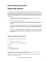
Fortunately, when Amstrad developed the CPC and CPC+ computers, they let the
user access many of the computer's internal routines (the firmware) and use them in
their own programs. Experienced coders will no doubt write faster or more versatile
code, yet these can easily be patched in using the Firmware Jumpblock.
For many years, Amstrad produced the definitive guide to the insides of the CPC but
sale of this was stopped in 1989. Since then the Firmware Manual has been a much
sought-after item by programmers. Nevertheless, the original guide had some
omissions, notably the abscence of information on the system variables and the Z80
microprocessor inside every CPC and CPC+.
This guide is not intended to explain how to program in machine code, but we hope
that it will supply the information needed to make the most of the Amstrad's
capabilities when writing your own programs.
Bob Taylor and Thomas Defoe, 1992
The Amstrad CPC Firmware Guide
3
4
The Amstrad CPC Firmware Guide
Contents
Use of Memory by the Operating System
7
Overview of the CPC
7
System Variables
8
Firmwire Guide
33
Kernel
35
Low Jumpblock
38
High Jumpblock
40
The Key Manager
43
The Text VDU
47
The Graphics VDU
53
The Screen Pack
57
Cassette / AMSDOS
63
AMSDOS / BIOS
66
The Sound Manager
69
The Machine Pack
71
664 / 6128 only
73
The Firmware Indirections
75
The Maths Firmware
77
Maths Subroutines for the 464 only
80
Maths Subroutines for the 664 and 6128 only
81
The Z80 Instruction Set
83
The Opcodes and T States
83
The Flag Register
83
The CRTC Registers
105
The Amstrad CPC Firmware Guide
5
6
The Amstrad CPC Firmware Guide
Use of memory by the
Operating System
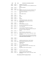
The following list of memory addresses and their uses has been compiled over a number of years,
mainly from personal investigation. It does not claim to be definitive, since no accurate source seems
to be available to the average computer user, and so may be inaccurate or deficient at certain points;
also, some of the areas described have uses additional to those listed. We have tried to make it as
accurate as possible, to enable others to use to the full those facilities which present themselves via
this information.
•
Addresses and values are present in memory with the low byte first. The Z80 processor
represents all 16-bit values in the order lo-byte hi-byte.
•
The term `above' means higher in memory.
•
Areas with numbers of bytes of either &00 or &FF given in brackets, may be safe to use for
machine code routines etc, as may the tape area, and the Sound ENT and ENT areas if these
are unused.
•
The first column given is the address (for the 6128) of the memory being considered, while the
second column gives the equivalent 464 address - unfortunately the 464 differs from the 6128
for most addresses, so if one address is omitted, the system variable is not available for that
machine.
•
The next column gives the size allocated in bytes. Addresses on the right hand side enclosed
in brackets are of System Variables which hold the address of the bytes being explained. With
addresses or values anywhere in the text, the value shown is for the 6128; a value in italics is
for the 464 only.
Overview of the CPC's memory
In the following tables, the following symbols are used:
<>
*
b0
b1
...
b15
HB
LB
-
not the value or bit which follows
this applies to all machine with a disk drive fitted
bit 0
bit 1
- bit 15
- most significant byte, hi-byte
- least significant byte, lo-byte
When addresses are given in the comments, they apply to the 6128. When the 464's address is
different, it is given in brackets, such as at the comment for &B763.
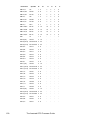
Please note that this section of the guide has been set out with all the addresses in the leftmost
column in the correct order for the 6128.
The Amstrad CPC Firmware Guide
7
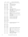
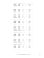
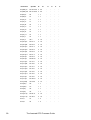
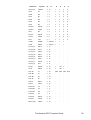
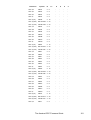
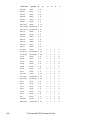
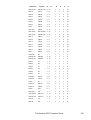
The System Variables
6128
464
Size
&40
Comments on the memory locations
&0000
&0000
&0000
&0000
RST 0: complete machine reset
&0008
&0008
RST 1: LOWJUMP: in-line two byte address: b0 to
b13=address;
b14=Low ROM disabled;
b15=Upper ROM disabled
&000B
&000B
LOW PCHL: HL has address as RST 1
&000E
&000E
`JMP BC': BC has address to jump to
&0010
&0010
RST 2: SIDE CALL: inline two byte address: b0 to
b13=address-&C000;
bl4 to b15=offset to required ROM (used between
sequenced Foreground ROMs)
&0013
&0013
SIDE PCHL: HL has address as RST 2
&0016
&0016
`JMP DE': DE has address to jump to
&0018
&0018
RST 3: FAR CALL: inline three byte address block: bytes 1
and 2 hold the address;
byte 3 holds the ROM select address
&001B
&001B
FAR PCHL: as RST 3, but HL has address;
C has ROM select
&001E
&001E
`JMP HL': HL has address to jump to
&0020
&0020
RST 4: RAM LAM: LD A,(HL) from RAM with ROMs
disabled
&0023
&0023
FAR CALL: as RST 3, but HL has address of three byte
address block
&0028
&0028
RST 5: FIRM JUMP: inline two byte address to jump to
&0030
&0030
RST 6: User restart;
default to RST 0
&0038
&0038
RST 7: Interrupt entry (KB/Time etc)
&003B
&003B
External interrupt (default to RET)
&0040
&0040
&016F
&016F
end of BASIC input area.
&0170
&0170
BASIC working area for program, variables, etc...
&0170
&0170
Program area;
Variables and DEF FNs area;
Arrays area;
Free space;
end of free space;
Strings area;
end of Strings area (=HIMEM);
Space for user machine code routines;
end of user space, byte before user;
defined graphics area;
User defined graphics area;
end of UDG area;
ROM Upper reserved area, expandible during;
&130
Restart block:
ROM lower foreground area: BASIC input area (tokenised)
KL ROM WALK, including:
r*4
8
ROM chaining blocks (arranged as follows):
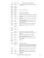
The Amstrad CPC Firmware Guide
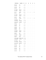
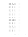
6128
464
Size
Comments on the memory locations
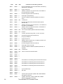
&A6FC
&A6FC
4
AMSDOS chain,ing block:
&A6FC
&A6FC
2
address of next ROM block in chain (or &0000 if the last in
chain)
&A6FE
&A6FE
1
ROM Select address
&A6FF
&A6FF
1
&00
&A700
&A700
&500
AMSDOS reserved area. This area is moved down if any
ROMs have numbers greater than eight (6128 only)
&A700
&A700
1
Current drive number (0=A;
1=B)
&A701
&A701
1
Current USER number
&A702
&A702
1
flag?
&A703
&A703
2
address?
&A705
&A705
1
flag?
&A706
&A706
2
address?
&A708
&A708
1
OPENIN flag (&FF=closed; <>&FF=opened)
&A709
&A709
&20
Copy of current or last Disc Directory entry for
OPENIN/LOAD:
&A709
&A709
1
USER number
&A70A
&A70A
8
filename (padded with spaces)
&A712
&A712
3
file extension (BAS, BIN, BAK, etc) including:
&A712
&A712
1
b7 set = Read Only
&A713
&A713
1
b7 set = System (ie not listed by CAT or DIR)
&A715
&A715
1
16K block sequence number for this directory entry (0 for
first block; if <>0 part of a larger file)
&A716
&A716
2
unused
&A718
&A718
1
length of this block in 128 byte records
&A719
&A719
16
sequence of Disc Block numbers containing file - &00 as
end marker
&A729
&A729
1
number of 128 byte records loaded so far; before loading
proper: &00 for ASCII (ie nothing loaded yet); &01 for BIN
or BAS files (ie header record loaded)
&A72A
&A72A
1
&A72B
&A72B
1
&A72C
&A72C
1
OPENOUT flag (&FF=closed; <>&FF=opened)
&A72D
&A72D
&20
Copy of current or last Disc Directory entry for
OPENOUT/SAVE:
&A72D
&A72D
1
USER number
&A72E
&A72E
8
filename (padded with spaces)
&A736
&A736
3
file extension ($$$ while open; correct extension when
finished)
&A739
&A739
1
flag (&00=open; &FF=closed, ie finished)
&A73A
&A73A
1
&A73B
&A73B
1
flag (&00=open; &FF=closed)
&A73C
&A73C
1
number of 128 byte records saved so far
&A73D
&A73D
16
sequence of Disc Block numbers containing file - &00 as
end marker
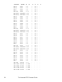
The Amstrad CPC Firmware Guide
9
6128
10
464
Size
Comments on the memory locations
&A74D
&A74D
1
number of 128 byte records saved so far
&A74E
&A74E
1
&A74F
&A74F
1
&A750
&A750
1
flag (&00=OPENIN; &01=In Char; &02=In Direct (whole
file))
&A751
&A751
2
address of 2K buffer for ASCII, or of start of current/last
block if BIN or BAS file
&A753
&A753
2
address of next byte to read for ASCII, or of 2K buffer for
BAS or BIN file
&A755
&A755
&45
first &45 bytes of BAS/BIN file (extended header) or of
extended header made for ASCII file
&A755
&A755
1
USER number
&A756
&A756
8
filename (padded)
&A75E
&A75E
3
extension
&A761
&A761
6
unused
&A767
&A767
1
file type (&00=BASIC; &01=protected BASIC; &02=Binary;
&16=ASCII)
&A768
&A768
2
unused
&A76A
&A76A
2
address to load file into (=actual destination), or buffer for
an ASCII file
&A76C
&A76C
1
unused for disc
&A76D
&A76D
2
length of file in bytes (&0000 for ASCII files)
&A76F
&A76F
2
execution address fora BIN file
&A770
&A770
&25
unused
&A795
&A795
3
length of actual file in bytes (as &A76D) -BAS and BIN only
&A798
&A798
2
simple checksum of first 67 bytes of header (LB first) - BAS
and BIN only
&A79A
&A79A
1
flag (&00=OPENOUT; &01=Out Char; &02=Out
Direct(whole file))
&A79B
&A79B
2
address of 2K block if an ASCII file, or of current/last block
saved if a BAS or BIN file
&A79D
&A79D
2
address of next byte to write for ASCII files, or of 2K buffer
for BAS and BIN files
&A79F
&A79F
&45
first &45 bytes of BAS/BIN file (ie extended header)
&A79F
&A79F
1
USER number
&A7A0
&A7A0
8
filename (padded)
&A7A8
&A7A8
3
extension
&A7AB
&A7AB
1
flag (&00=Open)
&A7AC
&A7AC 1
&A7AD
&A7AD 1
flag (&00=Open)
&A7AE
&A7AE
3
unused
&A7B1
&A7Bl
1
file type (&00=BASIC; &01=protected BASIC; &02=Binary;
&16=ASCII)
&A7B2
&A7B2
2
unused
&A7B4
&A7B4
2
address to save file from (for BAS or BIN files), or of buffer
for ASCII files
The Amstrad CPC Firmware Guide
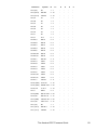
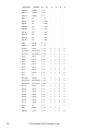
6128
464
Size
Comments on the memory locations
&A7B6
&A7B6
1
unused for disc
&A7B7
&A7B7
2
length of file in bytes
&A7B9
&A7B9
2
execution address for BIN files
&A7BB
&A7BB
&25
unused
&A7DF
&A7DF
3
length of actual file in bytes (as at &A7B7) - BAS and BIN
only
&A7E2
&A7E2
2
simple checksum of first 67 bytes of header (LB first) - BAS
and BIN only
&A7E4
&A7E4
&80
buffer area for records sent to or loaded from Disc, or used
in forming filename and extension
&A864
&A864
14*3
Tape Jumpblock is stored here by AMSDOS - is moved to
&BC77 etc after |TAPE
&A88B
&A88B
3
far address used by AMSDOS RST 3s at &BC77 etc
(&CD30,&07)
&A890
&A890
&19
Drive A Extended Disc Parameter Block (XDPB):
&A890
&A890
2
number of 128 byte records per track
&A892
&A892
1
log2(Block size)-7 (&03=1024 bytes; &04=2048 bytes)
&A893
&A893
1
(Block size)/128-1 (&07=1024 bytes;
&A894
&A894
1
(Block size)/1024 (if total of blocks <256, else /2048)-1
&A895
&A895
2
number of blocks per disc side (excluding reserved tracks)
&A897
&A897
2
number of (directory entries)-1
&A899
&A899
2
bit signiflcant value of number of blocks for directory
(&0080=1; &00C0=2)
&A89B
&A89B
2
number of bits in checksum =((&A894)+ 1)/4
&A89D
&A89D
2
number of reserved tracks (&00=Data; &01=IBM;
&02=System)
&A89F
&A89F
1
number of first sector (&01=IBM; &41=System; &C1=Data)
&A8A0
&A8A0
1
number of sectors per track (Data=9; System=9; IBM=8)
&A8A1
&A8Al
1
gap length (Read/Write)
&A8A2
&A8A2
1
gap length (Format)
&A8A3
&A8A3
1
format filler byte (&E5)
&A8A4
&A8A4
1
log2(sector size)-7 (&02=512; &03=1024)
&A8A5
&A8A5
1
records per sector
&A8A6
&A8A6
1
current track (not for use)
&A8A7
&A8A7
1
0=not aligned (not for use)
&A8A8
&A8A8
1
Auto select flag (&00=Auto select; &FF= don't alter)
&A8A9
&A8A9
&A8B9
&A8B9
&A8D0
&A8D0
&19
Drive B Extended Disc Parameter Block (arranged as at
&A890)
&A8E9
&A8E9
&A8F9
&A8F9
&A900
&A900
&A910
&A910
&A918
&A918
(&17 bytes of &FF)
(&12 bytes of &00)
2
address of area for reading directory entries for Drive A
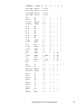
The Amstrad CPC Firmware Guide
11
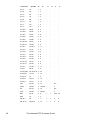
6128
464
Size
Comments on the memory locations
&A91A
&A91A
2
address of Drive A XDPB
&A91C
&A91C
2
address of the byte after the end of Drive A XDPB
&A91E
&A91E
2
&A920
&A920
&A928
&A928
2
address of area for reading directory entries for Drive B
&A92A
&A92A
2
address of Drive B XDPB
&A92C
&A92C
2
address of the byte after the end of Drive B XDPB
&A92E
&A92E
2
&A930
&A930
&80
block of directory entries, including last file loaded
&A9B0
&A9B0
&200
buffer for loading; usually contains last sector loaded
&ABB0
&ABB0
(&50 bytes of &00)
&AC00
&AC00
Start of BASIC Operating System reserved area:
&AC00
&AC00
1
program line redundant spaces flag (0=keep extra spaces;
<>0=remove)
&AC01
9*3
groups of 3 RET bytes (&C9) called by the Upper ROM
(8bytes of &00)
&AC01
&AC1C 1
AUTO flag (0=off; <>0=on)
&AC02
&AC1D 2
number of the next line (6128) or of the current line (464)
for AUTO
&AC04
&AC1F
2
step distance for AUTO
&AC06
&AC21
1
&AC07
&AC22
1
&AC08
1
&AC23
1
&AC09
&AC24
1
WIDTH (&84=132)
&AC0A
&AC25
&AC0B
12
&AC0C
&AC26
1
FOR/NEXT flag (0=NEXT not yet used; <>0=used)
&ACOD
&AC27
5
FOR start value (real). Only 2 bytes are used if % or
DEFINT variable
&AC12
&AC2C 2
address of `: ' or of the end of program line byte after a
NEXT command
&AC14
&AC2E 2
address of LB of the line number containing WEND
&AC16
&AC30
WHILE/WEND flag (&41=WEND not yet used; &04=used)
&AC17
&AC31
&AC18
&AC32
2
&AClA
&AC34
2
&AC1C
&AC36
2
address of location holding ROM routine address for KB
event block
&AC1E
&AC38
&0C
Event Block for ON SQ(l):
&AC1E
&AC38
2
chain address to next event block; &0000 if last in chain,
but &FFFF if unused
&AC20
&AC3A 1
count
&AC21
&AC3B 1
class: Far address, highest (ON SQ) priority, Normal &
Synchronous event
1
The Amstrad CPC Firmware Guide
6128
464
Size
Comments on the memory locations
&AC22
&AC3C 2
routine address (in BASIC ROM)
&AC24
&AC3E 1
ROM Select number (&FD ie ROM 0 enabled, Lower ROM
disabled)
&AC25
&AC3F
1
(first byte of user field)
&AC26
&AC40
2
address of the end of program line byte or `:' after `ON
SQ(x) GOSUB line number' statement
&AC28
&AC42
2
address of the end of program line byte of the line before
the GOSUB routine
&AC2A
&AC44
&0C
Event block for ON SQ(2), arranged as &AC1E onwards second ON SQ priority
&AC36
&AC50
&0C
Event block for ON SQ(4), arranged as &AC1E onwards lowest ON SQ priority
&AC42
&AC5C &12
Ticker and Event Block for AFTER/EVERY Timer 0
&AC42
&AC5C 2
chain address to next event block (usually to another timer
or &00FF)
&AC44
&AC5E 2
`count down' count
&AC46
&AC60
2
recharge count (for EVERY only - &0000 if AFTER)
&AC48
&AC62
2
chain address to next ticker block
&AC4A
&AC64
1
count
&AC4B
&AC65
1
class: Far address, lowest (timer) priority, Normal and
Synchronous event
&AC4C
&AC66
2
Routine address (in BASIC ROM)
&AC4E
&AC68
1
ROM Select No (&FD ie ROM 0 enabled, Lower ROM
disabled)
&AC4F
&AC69
1
(first byte of user field)
&AC50
&AC6A 2
address of the end of program line byte or `:' after
statement in use when the timer `timed-out'
&AC52
&AC6C 2
address of tbe end of program line byte of tbe line before
the GOSUB routine
&AC54
&AC6E &12
Ticker and Event Block for AFTER/EVERY Timer 1 (3rd
Timer priority) arranged as at &AC42
&AC66
&AC80
&12
Ticker and Event Block for AFTER/EVERY Timer 2 (2nd
Timer priority) arranged as at &AC42
&AC78
&AC92
&12
Ticker and Event Block for AFTER/EVERY Timer 3
(highest priority) arranged as at &AC42
&AC8A
&ACA4 &100
BASIC input area for lines (as typed in and not tokenised)
or for INPUT
&AD8C
&ADA6 2
address of line number LB in line containing error
&AD8E
&ADA8 2
address of byte before statement containing error - ie of `:'
or of HB of Line No
&AD90
&ADAA 1
ERR (Error No)
&AD91
1
&AD92
&ADAB 2
as &AD8E if error is in a program (ie not if in Direct
Command Mode)
&AD94
&ADAD 2
as &AD8C if error is in a program (ie not if in Direct
Command Mode)
&AD96
&ADAF 2
address of the length LB of line specified by the `ON
ERROR GOTO' command
&AD98
&ADB1 1
DERR (Disc Error No)
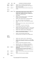
The Amstrad CPC Firmware Guide
13
6128
14
464
Size
Comments on the memory locations
&AD99
&ADB2 &09
Current SOUND parameter block (see Firmware Jump
&BCAA)
&AD99
&ADB2 1
channel andrendezvous status
&AD9A
&ADB3 1
amplitude envelope (ENV) number
&AD9B
&ADB4 1
tone envelope (ENT) number
&AD9C
&ADB5 2
tone period
&AD9E
&ADB7 1
noise period
&AD9F
&ADB8 1
initial amplitude
&ADA0
&ADB9 2
duration, or envelope repeat count
&ADA2
&ADBB &10
Current Amplitude or Tone Envelope parameter bloc (see
&BCBC or &BCBF)
&ADA2
&ADBB 1
number of sections (+&80 for a negative ENT number, ie
the envelope is run until end of sound
&ADA3
&ADBC 3
first section of the envelope:
&ADA3
&ADBC 1
step count (if <&80) otherwise envelope shape (not tone
envelope)
&ADA4
&ADBD 1
step size (if step count<&80) otherwise envelope period
(not tone envelope)
&ADA5
&ADBE 1
pause time (if step count<&80) otherwise envelope period
(not tone envelope)
&ADA6
&ADBF 3
second section of the envelope, as &ADA3
&ADA9
&ADC2 3
third section of the envelope, as &ADA3
&ADAC
&ADC5 3
fourth section of the envelope, as &ADA3
&ADAF
&ADC8 3
fifth section of the envelope, as &ADA3
&ADB2
&ADCB 5
&ADB7
&ADD0 &36
&ADEB
&AE04
2
&ADED
&AE06
6
&ADF3
&AE0C 26*1
&AE0D
&AE26
&AE0E
&AE27
2
&AE10
&AE29
2
&AE12
&AE2B
2
&AE14
&AE2D 1
&AE15
&AE2E
2
address of line number LB of last BASIC line (or &FFFF)
&AE17
&AE30
2
address of byte before next DATA item (eg comma or
space)
&AE19
&AE32
2
address of next space on GOSUB etc stack, (see also
&B06F)
&AE1B
&AE34
2
address of byte before current statement (&003F if in
Direct Command mode)
&AE1D
&AE36
2
address of line number LB of line of current statement
(&0000 if in Direct Command mode)
&AE1F
&AE38
1
trace flag (0=TROFF; <>0=TRON)
table of DEFINT (&02), DEFSTR (&03) or DEFREAL
default (&05), for variables `a' to `z'
The Amstrad CPC Firmware Guide
6128
464
Size
&AE20
&AE39
1
&AE21
&AE3A
&AE22
&AE3B
&AE24
&AE3D 2
&AE26
&AE3F
&AE28
&AE41
&AE29
Comments on the memory locations
flag used with Trace (&00 if in Direct Command mode; &01
if in a program)
2
2
address to load cassette file to
&AE42
1
file type from cassette header
&AE2A
&AE43
2
file length from cassette header
&AE2C
&AE45
1
program protection flag (<>0 hides program as if protected)
&AE2D
&AE46
17
buffer used to form binary or hexadecimal numbers before
printing etc
&AE3A
&AE53
5
start of buffer used to form hexadecimal numbers before
printing etc
&AE3A
&AE53
1
Key Number used with INKEY (providing the Key Number
is written as a decimal)
&AE3E
&AE57
1
last byte (usually &00 or &20) of the formed binary or
hexadecimal number
&AE43
&AE5D 13
buffer used to form decimal numbers before printing etc
&AE4E
&AE68
1
last byte (usually &00 or &20) of the formed decimal
number
&AE6B
3
&AE51
&AE52
1
&AE6E
&AE54
2
1
&AE70
2
temporary store for address after using (&AE68)
&AE55
&AE72
2
address of last used ROM or RSX JUMP instruction in its
Jump Block
&AE57
&AE74
1
ROM Select number if address above is in ROM
&AE58
&AE75
2
BASIC Parser position, moved on to `: `, or the end of
program line byte after a CALL or an RSX
&AE5A
&AE77
2
the resetting address for machine Stack Pointer after a
CALL or an RSX
&AE5C
&AE79
2
ZONE value
&AE5D
&AE5E
1
&AE7A
1
&AE7B
2
HIMEM (set by MEMORY)
&AE7D 2
address of the byte before the UDG area (the end of the
user M/C routine area or the Strings area) if the UDG area
is still present, otherwise the highest byte of Program etc
area
&AE60
2
address of highest byte of free RAM (ie last byte of UDG
area)
&AE62
&AE7F
2
address of start of ROM lower reserved area (used for
tokenised lines)
&AE64
&AE81
2
address of end of ROM lower reserved area (byte before
Program area)
&AE66
&AE83
2
as &AE68
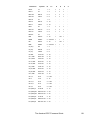
The Amstrad CPC Firmware Guide
15
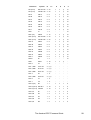
6128
464
Size
Comments on the memory locations
&AE68
&AE85
2
address of start of Variables and DEF FNs area
&AE6A
&AE87
2
address of start of Arrays area (where next Variable or
DEF FN entry is placed)
&AE6C
&AE89
2
address of start of free space (where next Array entry is
placed)
&AE6E
&AE70
1
&AE8C &1FF GOSUB, FOR and WHILE stack. Entries are added above
any existing ones in use (mixed as encountered) at
address given by &B06F and must be used up in the
opposite order. Completed entries are not deleted, just
overwitten by the next new entry:
1
(byte of &00)
2
address of end of program line byte or `:' after GOSUB
statement (the point to RETURN to)
2
address of line number HB of line containing GOSUB
1
byte of &06, ie the length of the GOSUB entry
2
address of current value of control variable (in Variables
area)
5
value of limit (ie the TO value) - there are two bytes only for
Integer FORs
5
value of STEP - two bytes for Integer FORs
1
sign byte (&00 for positive; &01 for negative)
2
address of the end of program line byte, or `:' after the FOR
statement (ie the address for the NEXT loop to restart at)
2
address of line number LB of line containing FOR
2
address of byte after NEXT statement (ie the address to
continue at when the limit is exceeded)
2
address of byte after NEXT statement again
1
length byte (&16 for Real FORs; &10 for Integer FORs)
2
address of line number LB of line containing WHILE
2
address of the end of program line byte or `:' after WEND
statement (ie the address to continue at when the condition
is false)
2
address of condition after the WHILE command
1
length byte of &07 - end of WHILE entry proper but:
+5
value of condition (0 or -1 as a floating point value) only
while the WHILE entry is the last on the stack
WHILE
(66 max
capacity):
&B06F
&B08B
2
address of the next space on the GOSUB etc stack (see
also &AE19)
NB: The free space on the stack is also used as a
workspace by various routines for values and addresses
and for Variable names
&B071
&B08D
2
address of end of free space (the byte before the Strings
area)
&B073
&B08F
2
address of end of Strings area (=HIMEM)
&B075
1
&B091
16
1
The Amstrad CPC Firmware Guide
6128
464
Size
Comments on the memory locations
&B092
2
&B076
&B094
2
&B078
&B096
2
&B07A
&B098
2
&B07C
&B09A
2
address for the next entry in the String Concatenation area
&B07E
&B09C
10*3
concatenation area holding descriptors of strings being
used
&B09C
&B0BA
1
length of last String used
&B09D
&B0BB
2
address of last String used
address of the highest byte of free RAM disregarding
UDGs (usually &A6FB)
&B0BD 2
&BOBF 2
&B09F
&BOC1 1
type byte used with the Virtual Accumulator (&02=Integer;
&03=String; &05=Real)
&B0A0
&B0C2
5
Virtual Accumulator used by the maths routines (two bytes
for an Integer value; three bytes for a String Descriptor; five
bytes for a Real value)
&B0A0
&B0C2
2
&B0A2
&B0C4
1
&B0A3
&B0C5
2
&B0A5
&B0C7
&5B
(&39 bytes on 464) bytes of &FF
&B100
&B8E4
2
&07, &C6
&B102
&B8E6
2
&65, &89
&B104
&B8E8
5
&B109
&B8ED 5
&B10E
&B8F2
5
&B113
&B8F7
1
&B114
&B8DC 1
&B115
&B8DD 1
&B116
&B8DE 1
&B117
&B8DF
1
&B118
&B800
&D2
Area used for Cassette handling:
&B118
&B800
1
cassette handling messages flag (0=enabled;
<>O=disabled)
&B119
&B801
1
&B11A
&B802
1
file IN flag (&00=closed; &02=IN file; &03=opened; &05=IN
char)
&B11B
&B803
2
address of 2K buffer for directories
&B11D
&B805
2
address of 2K buffer for loading blocks of files - often as
&B11B
&B11F
&B807
&40
IN Channel header
&B11F
&B807
&10
filename (padded with NULs)
&B12F
&B817
1
number of block being loaded, or next to be loaded
&B130
&B818
1
last block flag (&FF=last block; &00=not)
DEG/RAD flag (&00=RAD; &FF=DEG)
The Amstrad CPC Firmware Guide
17
6128
18
464
Size
Comments on the memory locations
&B131
&B819
1
file type (&00=BASIC; &01=Protected BASIC; &02=Binary;
&08=Screen; &16=ASCII)
&B132
&B81A
2
length of this block
&B134
&B81C
2
address to load this or the next block at,or the address of
the byte after last one loaded
&B136
&B81E
1
first block flag (&FF=first block; &00=not)
&B137
&B81F
2
total length of file (all blocks)
&B139
&B821
2
execution address for BIN files (&0000 if not saved as
such)
&B13B
&B823
&24
not allocated
&B15F
&B847
1
file OUT flag (&00=closed; &02=IN file; &03=opened;
&05=IN char)
&B160
&B848
2
address to start the next block save from, or the address of
the buffer if it is OPENOUT
&B162
&B84A
2
address of start of the last block saved, or the address of
the buffer if it is OPENOUT
&B164
&B84C
&40
OUT Channel Header (details as IN Channel Header):
&B164
&B84C
&10
filename
&B174
&B85C
1
number of the block being saved, or next to be saved
&B175
&B85D
1
last block flag (&FF=last block; &00=not)
&B176
&B85E
1
file type (as at &B131
&B177
&B85F
2
length saved so far
&B179
&B861
2
address of start of area to save, or address of buffer if it is
an OPENOUT instruction
&B17B
&B863
1
first block flag (&FF=first block; &00=not)
&B17C
&B864
2
total length of file to be saved
&B17E
&B866
2
execution address for BIN files (&0000 if parameter not
supplied)
&B180
&B868
&24
not allocated
&B1A4
&B88C
&40
used to construct IN Channel header:
&B1B5
&B89D
1
&B1B7
&B89F
2
&B1B8
&B8A3
1
&B1BE
&B8A6
1
&B1B9
&B51D
base address for calculating relevant Sound Channel block
&B1BC
&B520
base address for calculating relevant Sound Channel ?
&B1BE
&B522
base address for calculating relevant Sound Channel ?
&B1D5
&B539
base address for calculating relevant Sound Channel ?
&B1E4
&B8CC 1
&B1E5
&B8CD 1
synchronisation byte
&B1E6
&B8CE 2
&55, &62
&B1E8
&B8D0
1
&B1E9
&B8D1
1
cassette precompensation (default &06; SPEED WRITE 1
&0C @4microseconds)
&B1EA
&B8D2
1
cassette `Half a Zero' duration (default &53; SPEED
WRITE 1 &29 @ 4microseconds)
The Amstrad CPC Firmware Guide
6128
&B1EB
464
Size
Comments on the memory locations
&B8D3
2
&B550
1
used by sound routines
&B551
1
used by sound routines
1
used by sound routines
&B1ED
&B1EE
&B552
1
used by sound routines
&B1F0
&BB54
1
used by sound routines
&BB55
7
used by sound and cassette routines
&B1F8
&B55C
&3F
Sound Channel A (1) data:
&B212
&B576
1
number of sounds still queuing
&B213
&B577
1
number of sounds originally queuing
&B217
&B57B
8
first or fifth sound in Channel 1 (A) queue:
&B217
&B57B
1
status: b0 to b2 = rendezvous with channel 1, 2 or 4; b3 =
Hold; b4 = Flush
&B218
&B57C
1
b0 to b3 = tone envelope number; b4 to b7 = volume
envelope number (ie ENV number*16)
&B219
&B57D
2
pitch
&B21B
&B57F
1
noise
&B21C
&B580
1
volume
&B21D
&B581
2
duration (in 0.01 seconds)
&B21F
&B583
8
second sound in Channel 1 queue (as &B217)
&B227
&B58B
8
third sound in Channel 1 queue (as &B217)
&B22F
&B593
8
fourth sound in Channel 1 queue (as &B217)
&B237
&B59B
&3F
Sound Channel B (2) data - as described at &B1F8
&B256
&B5BA
8
first or fifth sound in Channel 2 queue (as &B217)
&B25E
&B5C2
8
second sound in Channel 2 queue (as &B217)
&B266
&B5CA 8
third sound in Channel 2 queue (as &B217)
&B26E
&B5D2
fourth sound in Channel 2 queue (as &B217)
&B276
&B5DA &3F
Sound Channel C (4) data - as described at &B1F8
&B295
&B5F9
8
first or fifth sound in Channel 4 queue (as &B217)
&B29D
&B601
8
2nd sound in Channel 4 queue (as &B217)
&B2A5
&B609
8
3rd sound in Channel 4 queue (as &B217)
&B2AD
&B611
8
4th sound in Channel 4 queue (as &B217)
&B2A6
&B60A
&B2B6
&B61A
15*16 ENV parameter block area (each arranged as &ADA2):
&B2B6
&B61A
&10
ENV 1
&B2C6
&B62A
&10
ENV 2
&B2D6
&B63A
&10
ENV 3
&B2E6
&B64A
&10
ENV 4
&B2F6
&B65A
&10
ENV 5
&B306
&B66A
&10
ENV 6
&B316
&B67A
&10
ENV 7
&B326
&B68A
&10
ENV 8
8
base address for calculating relevant ENV parameter block
The Amstrad CPC Firmware Guide
19
6128
464
Size
Comments on the memory locations
&B336
&B69A
&10
ENV 9
&B346
&B6AA
&10
ENV 10
&B356
&B6BA
&10
ENV 11
&B366
&B6CA &10
ENV 12
&B376
&B6DA &10
ENV 13
&B386
&B6EA
&10
ENV 14
&B396
&B6FA
&10
ENV 15
&B396
&B6FA
&B3A6
&B70A
15*16 ENT parameter block area (each arranged as &ADA2):
&B3A6
&B70A
&10
ENT 1
&B3B6
&B71A
&10
ENT 2
&B3C6
&B72A
&10
ENT 3
&B3D6
&B73A
&10
ENT 4
&B3E6
&B74A
&10
ENT 5
&B3F6
&B75A
&10
ENT 6
&B406
&B76A
&10
ENT 7
&B416
&B77A
&10
ENT 8
&B426
&B78A
&10
ENT 9
&B436
&B79A
&10
ENT 10
&B446
&B7AA
&10
ENT 11
&B456
&B7BA
&10
ENT 12
&B466
&B7CA &10
ENT 13
&B476
&B7DA &10
ENT 14
&B486
&B7EA
&10
ENT 15
&B496
&B34C
&50
Normal Key Table:
&B4E6
&B39C
base address for calculating relevant ENT parameter block
&50
Cur U Cur R Cur D f9
f6
f3
Enter f.
Cur L Copy f7
f8
f5
f1
f2
Clr
[
Ret
]
f4
^
-
@
p
;
:
/
.
0
9
o
i
l
k
m
j
8
7
u
y
h
j
n
Space
6
5
r
t
g
f
b
v
x
\
4
3
e
w
s
d
c
1
2
Esc
q
Tab
a
Caps z
[VT]
[LF]
[BS]
[TAB] Fire2 Fire1
Shifted Key Table:
Cur U Cur R Cur D f9 f6 f3 Enter f.
20
f0
Cur L Copy f7
f8 f5 f1 f2
Clr
{
Ret
}
£
=
|
P + * ?
>
_
)
O
I
<
(
'
U
Y H J N
Space
&
%
R
T G F B
V
$
#
E
W S D C
X
f4
f0
`
L K M
The Amstrad CPC Firmware Guide
Del
6128
464
Size
Comments on the memory locations
! "
Esc Q
->
A
Caps Z
[VT] [LF] [BS] [TAB] Fire2 Fire1 Del
&B536
&B3EC &50
Control Key Table:
Cur
Cur R Cur D f9
U
f6
f3
Enter f.
Cur
Copy f7
L
f8
f5
f1
f2
Clr
(GS)
f4
(ESC) Ret
(RS)
(NUL) (DLE)
(US)
(SI)
~
(FF)
(FS)
(VT)
(CR)
(NAK) (EM) (BS)
(LF)
(SO)
(DC2) (DC4) (BEL)
(ACK) (STX) (SYN)
(ENQ) (ETB) (DC3)
(EOT) (ETX) (CAN)
Esc
(HT)
f0
(DC1) Ins/Ovrt (SOH) S-lck (SUB)
Del
&B586
&B43C
10
KB repeats table (each byte/bit applies to all three key
tables): 1 byte is used per line of the tables; b0 to b7 give
the columns (left to right), repeat if set
&B590
&B446
&98
DEF KEY's definition area (for Keys &80 to &9F in
sequence): each definition has either a single byte of &00 if
it is unused/unaltered, or: byte 1: length of definition bytes
2 to x: definition, either a single key or a string of keys
&B628
&B4DE 1
&B629
&B4DF
1
&B62A
&B4E0
1
&B62B
&B4E1
2
address of DEF KEY area
&B62D
&B4E3
2
address of byte after end of DEF KEY area
&B62F
&B4E5
1
&B630
&B4E6
1
&B631
&B4E7
1
Shift lock flag (&00=off; &FF=on)
&B632
&B4E8
1
Caps lock flag (&00=off; &FF=on)
&B633
&B4E9
1
KB repeat period (SPEED KEY - default &02 @ 0.02
seconds)
&B634
&B4EA
1
KB delay period (SPEED KEY - default &1E @ 0.02
seconds)
&B635
&B4EB
2*10
Tables used for key scanning; bits 0 to 7 give the table
columns (from left to right):
&B635
&B4EB
1
&B636
&B4EC 1
Cur L Copy f7 f8 f5 f1 f2 f0
&B637
&B4ED 1
Clr [ Ret ] f4 Shift \ Ctrl
&B638
&B4EE
1
^ - @ p ; : / .
&B639
&B4EF
1
0 9 o i l k m j
&B63A
&B4F0
1
8 7 u y h j n Space
Byte after end of DEF KEY area
Cur U Cur R Cur D f9 f6 f3 Enter f.
The Amstrad CPC Firmware Guide
21
6128
&B63B
464
&B4F1
Size
1
Comments on the memory locations
Down Up Left Right Fire2 Fire1 (Joystick 1)
6
5
r
t
g
f
b
v
&B63C
&B4F2
1
4 3 e w s d c x
&B63D
&B4F3
1
1 2 Esc q Tab a Caps z
&B63E
&B4F4
1
Down Up Left Right Fire2 Fire1 (Joystick 2)
Del
22
&B63F
&B4F5
1
complement of &B635
&B640
&B4F6
1
complement of &B636
&B641
&B4F7
1
complement of &B637
&B642
&B4F8
1
complement of &B638
&B643
&B4F9
1
complement of &B639
&B644
&B4FA
1
complement of &B63A
&B645
&B4FB
1
complement of &B63B
&B646
&B4FC
1
complement of &B63C
&B647
&B4FD
1
complement of &B63D
&B648
&B4FE
1
complement of &B63E
&B64B
&B501
&B653
&B509
&B654
&B5OA 1
&B655
&B50B
1
&B656
&B50C
1
&B657
&B50D
7
event block for Keyboard handling, comprises:
&B657
&B50D
2
chain address
&B659
&B50F
1
count
&B65A
&B510
1
class: express event
&B65B
&B511
2
ROM routine address: &C492
&B65D
&B513
1
ROM select number: &FD
&B65E
&B514
20*2
store for last keys pressed and each entry is as follows:
byte 1: +0 to +10=key tables' line number; if bit 5 is set
then Shift is pressed; bit 7=Control is pressed byte 2: b0 to
b7=key tables' column number - see &B496 etc
&B67F
&B67F
2
vestige from the 464?
&B686
&B53C
1
&B687
&B53D
1
accumulated count of the number of keys pressed (MOD
20)
&B688
&B53E
1
number of keys left in key buffer
&B689
&B53F
1
accumulated count of the number of keys removed from
the buffer (MOD 20)
&B68A
&B540
1
&B68B
&B541
2
address of the normal key table
&B68D
&B543
2
address of the shifted key table
&B68F
&B545
2
address of the control key table
1
The Amstrad CPC Firmware Guide
6128
&B691
464
&B547
&B692
Size
2
Comments on the memory locations
address of the KB repeats table
1
&B693
&B328
2
ORIGIN x
&B695
&B32A
2
ORIGIN y
&B697
&B32C
2
graphics text x position (pixel)
&B699
&B32E
2
graphics text y position(pixel)
&B69B
&B330
2
graphics window x of one edge (pixel)
&B69D
&B332
2
graphics window x of other edge (pixel)
&B69F
&B334
2
graphics window y of one side (pixel)
&B6A1
&B336
2
graphics window y of other side (pixel)
&B6A3
&B338
1
GRAPHICS PEN
&B6A4
&B339
1
GRAPHICS PAPER
&B6A5
&B33A
8/14
(This area is 14 bytes on the 464) Used by line drawing
(and other) routines, as follows:
&B6A7
&B33A
2
x+1()
&B6A9
&B33C
2
y/2+1()
&B6AB
&B33E
2
y/2-x()
&B6AD
&B340
2
&B342
2
&B6AF
&B344
1
&B6B0
&B345
1
&B6B1
&B346
1
&B6B2
1
first point on drawn line flag (<>0=to be plotted; 0=don't
plot)
&B6B3
1
line MASK
&B6B4
1
&B207
2
&B6B5
&B20C
1
&B6B6
&B20D
14/15 (These areas are 15 bytes on the 464) Stream (window) 0
parameter block. These areas are arranged as &B726
&B6C4
&B21C
14/15 stream (window) 1 parameter block
&B6D2
&B22B
14/15 stream (window) 2 parameter block
&B6E0
&B23A
14/15 stream (window) 3 parameter block
&B6EE
&B249
14/15 stream (window) 4 parameter block
&B6FC
&B258
14/15 stream (window) 5 parameter block
&B70A
&B267
14/15 stream (window) 6 parameter block
&B718
&B276
14/15 stream (window) 7 parameter block
&B726
&B285
14/15 Current Stream (Window) parameter block:
&B726
&B285
1
cursor y position (line) with respect to the whole screen
(starting from 0)
&B727
&B286
1
cursor x position (column) with respect to the whole screen
(starting from 0)
&B728
&B287
current stream number
The Amstrad CPC Firmware Guide
23
6128
24
464
Size
Comments on the memory locations
&B729
&B288
1
window top line (y) with respect to the whole screen
(starting from 0)
&B72A
&B289
1
window left column (x) with respect to the whole screen
(starting from 0)
&B72B
&B28A
1
window bottom line (y) with respect to the whole screen
(starting from 0)
&B72C
&B28B
1
window right colwnn (x) with respect to the whole screen
(starting from 0)
&B72D
&B28C
1
scroll count
&B72E
&B28D
1
cursor flag (&01=disable; &02=off; &FD=on; &FE=enable)
&B28E
1
&B72F
&B28F
1
current PEN number (encoded, not its INK number)
&B730
&B290
1
current PAPER number (encoded, not its INK number)
&B731
&B291
2
address of text background routine: opaque=&1392;
transparent=&13A0
&B733
&B293
1
graphics character writing flag (0=off; <>0=on)
&B734
&B294
1
ASCII number of the first character in User Defined
Graphic (UDG) matrix table
&B735
&B295
1
UDG matrix table flag (&00=non-existent; &FF=present)
&B736
&B296
2
address of UDG matrix table
&B738
&B298
2
&B758
&B2B8
1
&B759
&B2B9
1
&B763
&B2C3
32*3
Control Code handling routine table - each code's entry
comprises: byte 1: +0 to +9=number of parameters;
+&80=re-run routine at a System Reset bytes 2 and 3:
address of the control code's handling routine
&B763
&B2C3
3
ASC 0: &80,&1513: NUL
&B766
&B2C6
3
ASC 1: &81,&1335: Print control code chararacter [,char]
&B769
&B2C9
3
ASC 2: &80,&1297: Disable cursor
&B76C
&B2CC 3
ASC 3: &80,&1286: Enable cursor
&B76F
&B2CF
3
ASC 4: &81,&0AE9: Set mode [,mode]
&B772
&B2D2
3
ASC 5: &81,&1940: Print character using graphics mode
[,char]
&B775
&B2D5
3
ASC 6: &00,&1459: Enable VDU
&B778
&B2D8
3
ASC 7: &80,&14E1: Beep
&B77B
&B2DB 3
ASC 8: &80,&1519: Back-space
&B77E
&B2DE 3
ASC 9: &80,&151E: Step-right
&B781
&B2E1
3
ASC 10: &80,&1523: Linefeed
&B784
&B2E4
3
ASC 11: &80,&1528: Previous line
&B787
&B2E7
3
ASC 12: &80,&154F: Clear window and locate the cursor
at position 1,1
&B78A
&B2EA
3
ASC 13: &80,&153F: RETURN
&B78D
&B2ED 3
ASC 14: &81,&12AB: Set paper [,pen]
&B790
&B2F0
ASC 15: &81,&12A6: Set pen [,pen]
3
The Amstrad CPC Firmware Guide
6128
464
Size
Comments on the memory locations
&B793
&B2F3
3
ASC 16: &80,&155E: Delete the character at the cursor
position
&B796
&B2F6
3
ASC 17: &80,&1599: Clear the line up to the current cursor
position
&B799
&B2F9
3
ASC 18: &80,&158F: Clear from the cursor position to the
end of the line
&B79C
&B2FC
3
ASC 19: &80,&1578: Clear from start of the window to the
cursor position
&B79F
&B2FF
3
ASC 20: &80,&1565: Clear from the cursor position to the
end of a window
&B7A2
&B302
3
ASC 21: &80,&1452: Disable VDU
&B7A5
&B305
3
ASC 22: &81,&14EC: Set text write mode [,mode]
&B7A8
&B308
3
ASC 23: &81,&0C55: Set graphics draw mode [,mode]
&B7AB
&B30B
3
ASC 24: &80,&12C6: Exchange pen and paper
&B7AE
&B30E
3
ASC 25: &89,&150D: Define user defined character
[,char,8 rows of char]
&B7B1
&B311
3
ASC 26: &84,&1501: Define window [,left,right,top,bottom]
&B7B4
&B314
3
ASC 27: &00,&14EB: ESC (=user)
&B7B7
&B317
3
ASC 28: &83,&14F1: Set the pen inks [,pen,ink 1,ink 2]
&B7BA
&B31A
3
ASC 29: &82,&14FA: Set border colours [,ink,ink2]
&B7BD
&B31D
3
ASC 30: &80,&1539: Locate the text cursor at position 1,1
&B7C0
&B320
3
ASC 31: &82,&1547: Locate the text cursor at
[,column,line]
&B7C3
&B1C8
1
MODE number
&B7C4
&B1C9
2
screen offset
&B7C6
&B1CB 1
screen base HB (LB taken as &00)
&B7C7
&B1CC 3
graphics VDU write mode indirection - JP &0C74
&B1CF
8
list of bytes having only one bit set, from b7 down to b0
&B7D2
&B1D7
1
first flash period (SPEED INK - default &0A @ 0.02
seconds)
&B7D3
&B1D8
1
second flash period (SPEED INK - default &0A @ 0.02
seconds)
&B7D4
&B1D9
1+16
Border and Pens' First Inks (as hardware numbers):
&B7D4
&B1D9
1
hw &04 = sw 1 (blue) border
&B7D5
&B1DA 1
hw &04 = sw 1 (blue) pen 0
&B7D6
&B1DB 1
hw &0A = sw 24 (bright yellow) pen 1
&B7D7
&B1DC 1
hw &13 = sw 20 (bright cyan) pen 2
&B7D8
&B1DD 1
hw &0C = sw 6 (bright red) pen 3
&B7D9
&B1DE 1
hw &0B = sw 26 (bright white) pen 4
&B7DA
&B1DF
1
hw &14 = sw 0 (black) pen 5
&B7DB
&B1E0
1
hw &15 = sw 2 (bright blue) pen 6
&B7DC
&B1E1
1
hw &0D = sw 8 (bright magenta) pen 7
&B7DD
&B1E2
1
hw &06 = sw 10 (cyan) pen 8
&B7DE
&B1E3
1
hw &1E = sw 12 (yellow) pen 9
&B7DF
&B1E4
1
hw &1F = sw 14 (pale blue) pen 10
The Amstrad CPC Firmware Guide
25
6128
464
Size
Comments on the memory locations
&B7E0
&B1E5
1
hw &07 = sw 16 (pink) pen 11
&B7E1
&B1E6
1
hw &12 = sw 18 (bright green) pen 12
&B7E2
&B1E7
1
hw &19 = sw 22 (pale green) pen 13
&B7E3
&B1E8
1
hw &04 = sw 1 (blue) pen 14
&B7E4
&B1E9
1
hw &17 = sw 11 (sky blue) pen 15
&B7E5
&B1EA
1+16
Border and Pens' Second Inks (as hardware numbers):
&B7E5
&B1EA
1
hw &04 = sw 1 (blue) border
&B7E6
&B1EB
1
hw &04 = sw 1 (blue) pen 0
&B7E7
&B1EC 1
hw &0A = sw 24 (bright yellow) pen 1
&B7E8
&B1ED 1
hw &13 = sw 20 (bright cyan) pen 2
&B7E9
&B1EE
1
hw &0C = sw 6 (bright red) pen 3
&B7EA
&B1FF
1
hw &0B = sw 26 (bright white) pen 4
&B7EB
&B1F0
1
hw &14 = sw 0 (black) pen 5
&B7EC
&B1F1
1
hw &15 = sw 2 (bright blue) pen 6
&B7ED
&B1F2
1
hw &0D = sw 8 (bright magenta) pen 7
&B7EE
&B1F3
1
hw &06 = sw 10 (cyan) pen 8
&B7EF
&B1F4
1
hw &1E = sw 12 (yellow) pen 9
&B7F0
&B1F5
1
hw &1F = sw 14 (pale blue) pen 10
&B7F1
&B1F6
1
hw &07 = sw 16 (pink) pen 11
&B7F2
&B1F7
1
hw &12 = sw 18 (bright green) pen 12
&B7F3
&B1F8
1
hw &19 = sw 22 (pale green) pen 13
&B7F4
&B1F9
1
hw &04 = sw 1 (bright yellow) pen 14
&B7F5
&B1FA
1
hw &17 = sw 11 (pink) pen 15
&B7F6
&B1FB
1
&B7F7
&B1FC
1
&B7F8
&B1FD
1
&B7F9
&BlFE
2
&B7FB
&B200
2
&B7FD
26
&B802
1+1
&B804
1
number of entries in the Printer Translation Table (normally
10)
&B805
20*2
Printer Translation Table; each entry comprises: byte 1:
screen code byte 2: pnnter code
&B805
2
screen &A0 printer &5E (acute accent)
&B807
2
screen &A1 printer &5C (\)
&B809
2
screen &A2 printer &7B ({)
&B80B
2
screen &A3 printer &23 (#)
&B80D
2
screen &A6 printer &40 (@)
&B80F
2
screen &AB printer &7C (|)
&B811
2
screen &AC printer &7D (})
&B813
2
screen &AD printer &7E (~)
The Amstrad CPC Firmware Guide
6128
464
Size
Comments on the memory locations
&B815
2
screen &AE printer &5D (])
&B817
2
screen &AF printer &SE ([)
&B819
20
room for ten more translations
&B82D
&B100
1
&B82E
&B101
1
&B82F
&B102
2
&B831
&B104
1
&B832
&B105
2
temporary store for stack pointer (SP) during interrupt
handling
&B834
&B107
&70
temporary machine stack (from &B8B3 downwards) during
interrupt handling
&B8B4
&B187
4
TIME (stored with the LB first - four bytes give >166 days;
three bytes give >15 hours)
&B8B8
&B18B
1
&B8B9
&B18C
2
&B8BB
&B18E
2
&B8BD
&B190
2
address of the first ticker block in chain (if any)
&B8BF
&B192
1
Keyboard scan flag (&00=scan not needed; &01=scan
needed)
&B8C0
&B193
2
address of the first event block in chain (if any)
&B8C2
&B195
1
&B8C3
&B196
&10
buffer for last RSX or RSX command name (last character
has bit 7 set)
&B8D3
&B1A6
2
address of first ROM or RSX chaining block in chain
1
RAM bank number
&B8D5
&B8D6
&B1A8
1
Upper ROM status (eg select number)
&B8D7
&B1A9
2
entry point of foreground ROM in use (eg &C006 for BASIC
ROM)
&B8D9
&B1AB
1
foreground ROM select address (0 for the BASIC ROM)
16*2
ROM entry IY value (ie the address table) - the 6128 has
ROMs numbered from 0 to 15:
&B8DA
&B1AC 7*2
ROM entry IY value (ie the address table)
&B8DA
2
ROM 0 IY (not for the 464)
&B8DC
&B1AC 2
ROM 1 IY
&B8DE
&B1AE
2
ROM 2 IY
&B8E0
&B1B0
2
ROM 3 IY
&B8E2
&B1B2
2
ROM 4 IY
&B8E4
&B1B4
2
ROM 5 IY
&B8E6
&B1B6
2
ROM 6 IY
&B8E8
&B1B8
2
ROM 7 IY (usually &A700 for AMSDOS/CPM ROM)
&B8EA
2
ROM 8 IY (not 464)
&B8EC
2
ROM 9 IY (not 464)
&B8EE
2
ROM 10 IY (not 464)
&B8F0
2
ROM 11 IY (not 464)
The Amstrad CPC Firmware Guide
27
6128
28
464
Size
Comments on the memory locations
&B8F2
2
ROM 12 IY (not 464)
&B8F4
2
ROM 13 IY (not 464)
&B8F6
2
ROM 14 IY (not 464)
&B8F8
2
ROM 15 IY (not 464)
&B8FA
6
6 bytes of &FF
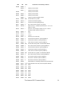
&B1BA
14
14 bytes of &00
&B900
&B900
12*3
High Kernel Jumpblock (on the 464 this block is 11*3 bytes
in size)
&B924
&B921
&1C0 routines used by the High Kernel Jumpblock (on the 464
this is &1C8 bytes in size)
&BAE4
&BAE9
&BB00
&BB00
26*3
Key Manager Jumpblock
&BB4E
&BB4E
36*3
Text VDU Jumpblock
&BBBA
&BBBA 23*3
Graphics VDU Jumpblock
&BBFF
&BBFF
34*3
Screen Pack Jumpblock
&BC65
&BC65
22*3
Cassette (and Disc if fitted) Manager Jumpblock
&BCA7
&BCA7 11*3
Sound Manager Jumpblock
&BCC8
&BCC8 25*3
Kernel Jumpblock
&BD13
&BD13
26*3
Machine Pack Jumpblock (on the 464 this block is 14*3
bytes in size)
&BD61
&BD3D 32*3
Maths Jumpblock (on the 464 this block is 48*3 bytes in
size)
&BDCD
&BDCD 14*3
Firmware Indirections (on the 464 this block is 13*3 bytes
in size
&BDF7
&BDF4
bytes of &00 (&09 bytes on 6128, &0C bytes on the 464)
the lower limit of Machine Stack if no Disc Drive
&BE00
&BE00
&40
&40 bytes of &FF
&BE40
&BE40
&4x
used by the AMSDOS ROM if a disc drive is fitted
(otherwise &4x bytes of &FF)
&BE40
&BE40
2
(address &A910)
&BE42
&BE42
2
address of drive A XDPB
&BE44
&BE44
9
Disc Set Up timing block:
&BE44
&BE44
2
motor on period (default &0032; fastest &0023 @ 20mS)
&BE46
&BE46
2
motor off period (default &00FA; fastest &00C8 @ 20mS)
&BE48
&BE48
1
write current off period (default &AF @ 10æS)
&BE49
&BE49
1
head settle time (default &0F @ 1mS)
&BE4A
&BE4A
1
step rate period (default &0C; fastest &0A @ 1mS)
&BE4B
&BE4B
1
head unload delay (default &01)
&BE4C
&BE4C 1
&BE4D
&BE4D 2
&BE4F
&BE4F
1
Drive Header Information Block:
&BE4F
&BE4F
1
last track used
&BE50
&BE50
1
head number (&00)
&BE51
&BE51
1
last sector used
bytes of &FF (&1C bytes on 6128, &17 bytes on 464)
b0=non DMA mode; b1 to b7=head load delay (default
&03)
The Amstrad CPC Firmware Guide
6128
464
Size
Comments on the memory locations
&BE52
&BE52
1
&BE53
&BE53
1
&BE54
&BE54
1
&BE55
&BE55
1
&BE56
&BE56
1
&BE58
&BE58
1
&BE59
&BE59
1
&BE5D
&BE5D 1
&BE5E
&BE5E
1
&BE5F
&BE5F
1
disc motor flag (&00=off;&01=on - strangely reversed)
&BE60
&BE60
2
address of buffer for directory entries block (&A930)
&BE62
&BE62
2
as &BE76 (ie&A9B0)
&BE64
&BE64
2
&BE66
&BE66
1
disc retries (default &10)
&BE67
&BE67
&11
AMSDOS Ticker and Event Block:
&BE67
&BE67
2
ticker chaining address
&BE69
&BE69
2
tick count
&BE6B
&BE6B
2
recharge count
&BE6D
&BE6D 2
event chaining address
&BE6F
&BE6F
1
count
&BE70
&BE70
1
class (asynchronous event)
&BE71
&BE71
2
ROM routine address (&C9D6)
&BE73
&BE73
1
ROM select number (&07 ie the AMSDOS/CPM ROM)
&BE74
&BE74
1
last sector number used
&BE75
&BE75
1
&BE76
&BE76
2
address of «K buffer, or of header info block (for WRlTE
SECTOR etc)
&BE78
&BE78
1
disc error message flag (&00=on; &FF=off - reversed
again)
&BE7D
&BE7D 2
address of AMSDOS reserved area (&A700)
&BE7F
&BE7F
x
area used by AMSDOS to copy routines into RAM for
running
&BE80
&BE80
&80
&80 bytes of &FF (limit of machine stack if disc drive fitted)
&BF00
&BF00
xy
&xy bytes of &00)
&BFxy
&BFFF
log2(sector size)-7
machine stack (in theory this stack could extend down
much further)
&BFFF
upper limit of machine stack
The Amstrad CPC Firmware Guide
29
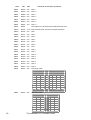
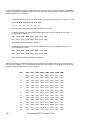
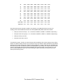
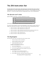
The area from &C000 to &FFFF is taken up by the screen memory - the layout of which is illustrated
below. Printed below are diagrams which show how the CPC uses the bytes of screen memory in the
different MODEs. For each byte:
•
in MODE 2 (where there are two colours only, each pixel needs only one bit - either on or off)
bit7 bit6 bit5 bit4 bit3 bit2 bit1 bit0
p0
p1
p2
p3
p4
p5
p6
p7
•
(the pixels are arranged with p0 being the leftmost one, etc)
•
in MODE 1 (where four colours are available and so two bits are needed for each pixel - 1
byte represents 4 pixels)
bit7
bit6
bit5
bit4
bit3
bit2
bit1
bit0
p0(1) p1(1) p2(1) p3(1) p0(0) p1(0) p2(0) p3(0)
•
(each pixel is twice as wide as in MODE 2)
•
in MODE 0 (where sixteen colours are possible and four bits are needed for each pixel - 1
byte represents 2 pixels)
bit7
bit6
bit5
bit4
bit3
bit2
bit1
bit0
p0(0) p1(0) p0(2) p1(2) p0(1) p1(1) p0(3) p1(3)
•
(each pixel is four times as wide as in MODE 2)
NB: The numbers in brackets show which bit of the pixel's pen number the screen byte bit refers to.
For example in MODE 1, the 4 most significant bits of the byte hold bit 1 of the pixel's pen value and
the least signifcant bits hold bit 0 of the pen value.
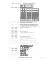
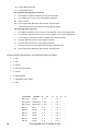
LINE
30
R0W0 R0W1 R0W2 R0W3 R0W4 R0W5 R0W6 R0W7
1
C000
C800
D000
D800
E000
E800
F000
F800
2
C050
C850
D050
D850
E050
E850
F050
F850
3
C0A0
C8A0
D0A0
D8A0
E0A0
E8A0
F0A0
F8A0
4
C0F0
C8F0
D0F0
D8F0
E0F0
E8F0
F0F0
F8F0
5
C140
C940
D140
D940
E140
E940
F140
F940
6
C190
C990
D190
D990
E190
E990
F190
F990
7
C1E0
C9E0
D1E0
D9E0
E1E0
E9E0
F1E0
F9E0
8
C230
CA30
D230
DA30
E230
EA30
F230
FA30
9
C280
CA80
D280
DA80
E280
EA80
F280
FA80
10
C2D0
CAD0 D2D0
DAD0 E2D0
EAD0
F2D0
FAD0
11
C320
CB20
D320
DB20
E320
EB20
F320
FB20
12
C370
CB70
D370
DB70
E370
EB70
F370
FB70
13
C3C0
CBC0 D3C0
DBC0 E3C0
EBC0
F3C0
FBC0
14
C410
CC10
D410
DC10
E410
EC10
F410
FC10
15
C460
CC60
D460
DC60
E460
EC60
F460
FC60
The Amstrad CPC Firmware Guide
16
C4B0
CCB0 D4B0
DCB0 E4B0
ECB0
F4B0
FCB0
17
C500
CD00
D500
DD00
E500
ED00
F500
FD00
18
C550
CD50
D550
DD50
E550
ED50
F550
FD50
19
C5A0
CDA0 D5A0
DDA0 E5A0
EDA0
F5A0
FDA0
20
C5F0
CDF0 D5F0
DDF0
E5F0
ED50
F550
FD50
21
C640
CE40
D640
DE40
E640
EE40
F640
FE40
22
C690
CE90
D690
DE90
E690
EE90
F690
FE90
23
C6E0
CEE0 D6E0
DEE0
E6E0
EEE0
F6E0
FEE0
24
C730
CF30
D730
DF30
E730
EF30
F730
FF30
25
C780
CF80
D780
DF80
E780
EF80
F780
FF80
spare start C7D0
CFD0 D7D0
DFD0
E7D0
EFD0
F7D0
FFD0
spare end
CFFF
DFFF
E7FF
EFFF
F7FF
FFFF
C7FF
D7FF
Once the whole screen has been scrolled in any direction, the table will become incorrect. On
scrolling, all the above addresses will have an offset (MOD &800) added, derived as follows:
•
+&02 per scroll to the left (2, 1 or ½ character in MODE 2, MODE 1 or MODE 0 respectively)
•
-&02 per scroll to the right (2, 1 or ½ character in MODE 2, MODE 1 or MODE 0 respectively)
•
+&50 per scroll up one line
•
-&50 per scroll down one line
If scrolled far enough, a screen row may sit across the boundaries of the screen memory area, whose
bottom end will then wrap around to join up with the top (ie byte &FFFF will be followed by byte &C000
assuming the normal screen area). If before scrolling however, a window had been set up smaller than
the whole screen then the table will remain accurate despite any scrolling. The `spare' areas of screen
memory are filled with bytes of the relevant PAPER value each time there is a full screen CLS, and
are not really available for other uses. After scrolling the spare areas may be used as screen with
other bytes becoming spare.
The Amstrad CPC Firmware Guide
31
32
The Amstrad CPC Firmware Guide
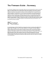
The Firmware Guide – Summary
The Firmware Jumpblock is the recommended method of communicating with the routines in the lower
ROM - it is used by BASIC, and it should also be used by other programs. The reason for using the
jumpblock is that the routines in the lower ROM are located at different positions on the different
machines. The entries in the jumpblock, however, are all in the same place - the instructions in the
jumpblock redirect the computer to the correct place in the lower ROM. Thus, providing a program
uses the jumpblock, it should work on any CPC computer. By altering the firmware jumpblock it is
possible to make the computer run a different routine from normal. This could either be a different
routine in the lower or upper ROM, or a routine written by the user - this is known as 'patching the
jumpblock'. It is worth noting that because BASIC uses the firmware jumpblock quite heavily, it is
possible to alter the effect of BASIC commands. The following example will change the effect of calling
SCR SET MODE (&BC0E) - instead of changing the mode, any calls to this location will print the letter
'A'. The first thing to do is to assemble the piece of code that will be used to print the letter - this is
printed below and starts at &4000.
ORG &4000
LD A,65
; 65 is ASCII FOR 'A'
CALL &BB5A ; TXT OUTPUT
RET
; return from subroutine
The jumpblock entry for SCR SET MODE is now patched so that it reroutes all calls to &BC0E away
from the lower ROM and to our custom routine at &4000. This is done by changing the bytes at
&BC0E, &BC0F and &BC10 to &C3, &00, &40 respectively (ie JP &4000). Any calls to &BC0E or
MODE commands will now print the letter A instead of changing mode. The indirections jumpblock
contains a small number of routines which are called by the rest of the firmware. By altering this
jumpblock, it is possible to alter the way in which the firmware operates on a large scale - thus it is not
always necessary to patch large numbers of entries in the firmware jumpblock. There are two
jumpblocks which are to do with the Kemel (ie the high and low Kernel jumpblocks). The high
jumpblock allows ROM states and interrupts to be altered, and also controls the introduction of RSXs.
The low jumpblock contains general routines and restart instructions which are used by the computer
for its own purposes.
The Amstrad CPC Firmware Guide
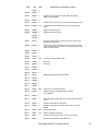
33
34
The Amstrad CPC Firmware Guide
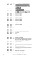
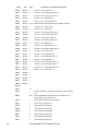
The Kernel
&BCC8 KL CHOKE OFF
Action
Clears all event queues and timer lists, with the exception of keyboard scanning and sound routines
Entry
No entry conditions
Exit
B contains the foreground ROM select address (if any), DE contains the ROM entry address, C holds
the ROM select address for a RAM foreground program, AF and HL are corrupt, and all others are
preserved
&BCCB KL ROM WALK
Action
Finds and initialises all background ROMs
Entry
DE holds the address of the first usable byte of memory, HL holds the address of the last usable byte
Exit
DE holds the address of the new first usable byte of memory, HL holds the address of the new last
usable byte, AF and BC are corrupt, and all other registers are preserved
Notes
This routine looks at the ROM select addresses from 0 to l5 (1 to 7 for the 464) and calls the
initialisation routine of any ROMs present; these routines may reserve memory by adjusting DE and HL
before returning control to KL ROM WALK, and the ROM is then added to the list of command handling
routines
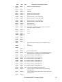
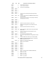
&BCCE KL INIT BACK
Action
Finds and initialises a specific background ROM
Entry
C contains the ROM select address of the ROM, DE holds the address of the first usable byte of
memorv, HL holds the address of the last usable byte of memory
Exit
DE holds the address of the new first usaUe byte of memory, HL holds the address of the new last
usable byte. AF and B are corrupt, and all other registers are preserved
Notes
The ROM select address must be in the range of 0 to 15 (or 1 to 7 for the 464) although address 7 is tor
the AMSDOS/CPM ROM if present. The ROM's initialisation routine is then called and some memory
may be reserved for the ROM by adjusting the values of DE and HL before returning control to KL INlT
BACK
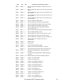
&BCD1 KL LOG EXT
Action
Logs on a new RSX to the firmware
Entry
BC contains the address of the RSX's command table, HL contains the address of four bytes
exclusively for use by the firmware
Exit
DE is corrupt, and all other registers are preserved
&BCD4 KL FIND COMMAND
Action
Searches an RSX, background ROM or foreground ROM, to find a command in its table
Entry
HL contains the address of the command name (in RAM only) which is being searched for
Exit
If the narne was found in a RSX or background ROM then Carry is true, C contains the ROM select
address, and HL contains the address of the routine; if the command was not found, then Carry is false,
C and HL are corrupt; in either case, A, B and DE are corrupt, and all others are preserved
Notes
The command names should be in upper case and the last character should have &80 added to it; the
sequence of searching is RSXs, then ROMs with lower numbers before ROMs with higher numbers
&BCD7 KL NEW FRAME FLY
Action
Sets up a frame flyback event block which will be acted on whenever a frame flyback occurs
Entry
HL contains the address of the event block in the central 32K of RAM, B contains the event class. C
contains the ROM select address (if any), and DE contains the address if the event routine
Exit
AF, DE and HL are corrupt, and all other registers are preserved
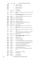
&BCDA KL ADD FRAME FLY
Action
Adds an existing but deleted frame flyback event block to the list of routines run when a frame flyback
occurs
Entry
HL contains the address of the event block (in the central 32K of RAM)
The Amstrad CPC Firmware Guide
35
Exit
AF, DE and HL are corrupt, and all others are preserved
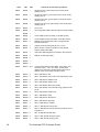
&BCDD KL DEL FRAME FLY
Action
Removes a frame flyback event block from the list of routines which are mn when a frame flyback
occurs
Entry
HL contains the address of the event block
Exit
AF, DE and HL are corrupt, and all others are preserved
&BCE0 KL NEW FAST TICKER
Action
Sets up a fast ticker event block which will be run whenever the l/300th second ticker interrupt occurs
Entry
HL contains the address of the event block (in the central 32K of RAM), B contains the event class, C
contains the ROM select address (if any), and DE contains the address of the event routine
Exit
AF, DE and HL are corrupt, and all other registers are preserved
&BCE3 KL ADD FAST TICKER
Action
Adds an existing but deleted fast ticker event block to the list of routines which are run when the l/300th
sec ticker interrupt occurs
Entry
HL contains the address of the event block
Exit
AF, DE and HL are corrupt, and all the other registers are preserved
&BCE6 KL DEL FAST TICKER
Action
Removes a fast ticker event block from the list of routines run when the l/300th sec ticker interrupt
occurs
Entry
HL contains the address of the event block
Exit
AF, DE and HL are corrupt, and all others are preserved
&BCE9 KL ADD TICKER
Action
Sets up a ticker event block which will be run whenever a 1/50th second ticker interrupt occurs
Entry
HL contains the address of the event block (in the central 32K of RAM), DE contains the initial value for
the counter, and BC holds the value that the counter will be given whenever it reaches zero
Exit
AF, BC, DE and HL are corrupt, and all the other registers are preserved
Notes
Every 1/50th of a second all the tick blocks are looked at and their counter is decreased by 1; when the
counter reaches zero, the event is `kicked' and the counter is loaded with the value in BC; any tick block
with a counter of 0 is ignored, and therefore if the value in BC is 0, the event will be kicked only once
and ignored after that
&BCEC KL DEL TICKER
Action
Removes a ticker event block from the list of routines that are run when a l/50th sec ticker interrupt
occurs
Entry
HL contains the address of the event block
Exit
If the event block was found, then Carry is true, and DE holds the value remaining of the counter; if the
event block was not found, then Carry is false, and DE is corrupt; in both cases, A, HL and the other
flags are corrupt, and all other registers are preserved
&BCEF KL INIT EVENT
Action
Initialises an event block
Entry
HL contains the address of the event block (in the central 32K of RAM), B contains the class of event,
and C contains the ROM select address, and DE holds the address of the event routine
Exit
HL holds the address of the event block+7, and all other registers are preserved
Notes
The event class is derived as follows
bit 0 -indicates a near address
bits 1 to 4 - hold the synchronous event priority
bit 5 - always zero
bit 6 - if bit 6 is set, then it is an express event
bit 7 - if bit 7 is set, then it is an asynchronous event.
Asynchronous events do not have priorities; if it is an express asynchronous event, then its event
routine is called from the interrupt path; if it is a normal asynchronous event, then its event routine is
called just before returning from the interrupt; if it is an express synchronous event, then it has a higher
36
The Amstrad CPC Firmware Guide
priority than normal synchronous events, and it may not be disabled through use of KL EVENT
DISABLE; if the near address bit is set, then the routine is located in the central 32K of RAM and is
called directly, so saving time; no event may have a priority of zero
&BCF2
KL EVENT
Action
Kicks an event block
Ently
HL contains the address of the event block
Exit
AF, BC, DE and HL are corrupt, and all other registers are preserved
&BCF5
KL SYNC RESET
Action
Clears the synchronous event queue
Entry
No entry conditions
Exit
AF and HL are corrupt, and all other registers are preserved
Notes
When using this routine, all events that are waiting to be dealt with are simply discarded
&BCF8
KL DEL SYNCHRONOUS
Action
Removes a synchronous event from the event queue
Entry
HL contains the address of the event block
Exit
AF, BC, DE and HL are corrupt, and all other registers are preserved
&BCFB KL NEXT SYNC
Action
Finds out if there is a synchronous event with a higher priority
Entry
No entry conditions
Exit
If there is an event to be processed, then Carry is true, HL contains the address of the event block, and
A contains the priority of the previous event; if there is no event to be processed, then Carry is false,
and A and HL are corrupt; in either case, DE is corrupt, and all other registers are preserved
&BCFE KL DO SYNC
Action
Runs a synchronous event routine
Entry
HL contains the address of the event block
Exit
AF, BC, DE and HL are corrupt, and all other registers are preserved
Notes
See KL DONE SYNC below
&BD01
KL DONE SYNC
Action
Finishes running a synchronous event routine
Entry
A contains the priority of the previous event, and HL contains the address of the event block
Exit
AF, BC, DE and HL are corrupt, and all other registers are preserved
Notes
When an event that is waiting to be processed has been found by KL NEXT SYNC, the event routine
should be run by KL DO SYNC; after this KL DONE SYNC should be called so that the event counter
can be decreased - if the counter is greater than zero then the event is placed back on the synchronous
event queue
&BD04
KL EVENT DISABLE
Action
Disables norrnal synchronous events
Entry
No entry conditions
Exit
HL is corrupt, and all other registers are preserved
&BD07
KL EVENT ENABLE
Action
Enables normal synchronous events
Entry
No entry conditions
Exit
HL is corrupt, and all other registers are preserved
&BD0A KL DISARM EVENT
Action
Disarrns a specific event and stops it from occurring
The Amstrad CPC Firmware Guide
37
Entry
HL contains the address of the event block
Exit
AF is corrupt, and all other registers are preserved
Notes
This routine should be used to disarm only asynchronous events; see also KL DEL SYNCHRONOUS
&BD0D KL TIME PLEASE
Action
Returns the time that has elapsed since the computer was switched on or reset (in 1/300ths of a
second)
Entry
No entry conditions
Exit
DEHL contains the four byte count of the time elapsed, and all other registers are preserved
Notes
D holds the most signifilcant byte of the time elapsed, and L holds the least significant; the four byte
count overflows after approximately l66 days have elapsed.
&BD10
KL TIME SET
Action
Sets the elapsed time (in l¡300ths of a second)
Entry
DEHL contains the four byte count of the time to set
Exit
AF is corrupt, and all other registers are preserved
Low Kernel Jumpblock
&0000 RESET ENTRY (RST 0)
Action
Resets the computer as if it has just been switched on
Entry
No entry conditions
Exit
This routine is never returned from
Notes
After initialisation of the hardware and firmware, control is handed over to ROM 0 (usually BASIC)
&0008 LOW JUMP (RST 1)
Action
Jumps to a routine in either the lower ROM or low RAM
Entry
No entry conditions - all the registers are passed to the destination routine unchanged
Exit
The registers are as set by the routine in the lower ROM or RAM or are returned unaltered
Notes
The RST 1 instruction is followed by a two byte low address, which is defmed as follows
if bit 15 is set, then the upper ROM is disabled
if bit 14 is set, then the lower ROM is disabled
bits 13 to 0 contain the address of the routine to jump to. This command is used by the majority of entries
in the main firmware jumpblock
&000B KL LOW PCHL
Action
Jumps to a routine in either the lower ROM or low RAM
Entry
HL contains the low address - all the registers are passed to the destination routine unchanged
Exit
The registers are as set by the routine in the lower ROM or RAM or are returned unaltered
Notes
The two byte low address in the HL register pair is defined as follows
if bit 15 is set, then the upper ROM is disabled
if bit 14 is set, then the lower ROM is disabled
bits 13 to 0 contain the address of the routine to jump to
&000E PCBC INSTRUCTION
Action
Jumps to the specified address
Entry
BC contains the address to jump to - all the registers are passed to the destination routine unaltered
Exit
The registers are as set by the destination routine or are returned unchanged
&0010 SIDE CALL (RST 2)
Action
Calls a routine in ROM, in a group of up to four foreground ROMs
Entry
No entry conditions - all the registers apart from IY are passed to the destination routine unaltered
38
The Amstrad CPC Firmware Guide
Exit
IY is corrupt, and the other registers are as set by the destination routine or are returned unchanged
Notes
The RST 2 instruction is followed by a two byte side address, which is defined as follows
bits 14 and 15 give a number between 0 and 3, which is added to the main foreground ROM select
address - this is then used as the ROM select address bits 0 to 13 contain the address to which is added
&C000 - this gives the address of the routine to be called
&0013 KL SIDE PCHL
Action
Calls a routine in another ROM
Entry
HL contains the side address - all the registers apart from IY are passed to the destination routine
unaltered
Exit
IY is corrupt, and the other registers are as set by the destination routine or are returned unchanged
Notes
The two byte side address is defined as follows
bits 14 and 15 give a number between 0 and 3, which is added to the main foreground ROM select
address - this is then used as the ROM select address bits 0 to 13 contain the address to which is added
&C000 - this gives the address of the routine to be called
&0016 PCDE INSTRUCTION
Action
Jumps to the specified address
Entry
DE contains the address to jump to - all the registers are passed to the destination routine unaltered
Exit
The registers are as set by the destination routine or are returned unchanged
&0018 FAR CALL (RST 3)
Action
Calls a routine anywhere in ROM or ROM
Entry
No entry conditions - all the registers apart from IY are passed to the destination routine unaltered
Exit
IY is preserved, and the other registers are as set by the destination routine or are returned unchanged
Notes
The RST 3 instruction is followed by a two byte in-line address. At this address, there is a three byte far
address, which is defined as follows
bytes 0 and 1 give the address of the routine to be called
byte 2 is the ROM select byte which has values as follows
&00 to &FB-- select the given upper ROM, enable the upper ROM and disable the lower ROM
&FC - no change to the ROM selection, enable the upper and lower ROMs
&FD - no change to the ROM selection, enable the upper ROM and disable the lower ROM
&FE - no change to the ROM selection, disable the upper ROM and enable the lower ROM
&FF - no change to the ROM selection, disable the upper and lower ROMs
When it is retumed from, the ROM selection and state are restored to their settings before the RST 3
command
&001B KL FAR PCHL
Action
Calls a routine, given by the far address in HL & C, anywhere in RAM or ROM
Entry
HL holds the address of the routine to be called, and C holds the ROM select byte - all the registers apart
from IY are passed to the destination routine unaltered
Exit
IY is preserved, and the other registers are as set by the destination routine or are returned unchanged
Notes
See FAR CALL (RST 3) above for more details on the ROM select byte
&001E PCHL INSTRUCTION
Action
Jumps to the specified address
Entry
HL contains the address to jump to - all the registers are passed to the destination routine unaltered
Exit
The registers are as set by the destination routine or are returned unchanged
&0020 RAM LAM
Action
Puts the contents of a RAM memory location into the A register
Entry
HL contains the address of the memory location
Exit
A holds the contents of the memory location, and all other registers are preserved
Notes
This routine always reads from RAM, even if the upper or lower ROM is enabled
&0023 KL FAR CALL
Action
Calls a routine anywhere in RAM or ROM
The Amstrad CPC Firmware Guide
39
Entry
HL holds the address of the three byte far address that is to be used - all the registers apart from IY are
passed to the destination routine unaltered
Exit
IY is preserved, and the other registers are as set by the destination routine or are returned unchanged
Notes
See FAR CALL above for more details on the three byte far address
&0028 FIRM JUMP (RST 5)
Action
Jumps to a routine in either the lower ROM or the central 32K of RAM
Entry
No entry conditions - all the registers are passed to the destination routine unchanged
Exit
The registers are as set by the routine in the lower ROM or RAM or are returned unaltered
Notes
The RST 5 instruction is followed by a two byte address, which is the address to jump to; before the jump
is made, the lower ROM is enabled, and is disabled when the destination routine is returned from
&0030 USER RESTART (RST 6)
Action
This is an RST instruction that may be set aside by the user for any purpose
Entry
Defined by the user
Exit
Defined by the user
Notes
The bytes from &0030 to &0037 are available for the user to put their own code in if they wish
&0038 INTERRUPT ENTRY (RST 7)
Action
Deals with normal interrupts
Entry
No entry conditions
Exit
All registers are preserved
Notes
The RST 7 instruction must not be used by the user; any external interrupts that are generated by
hardware on the expansion port will be dealt with by the EXT INTERRUPT routine (see Low Kernel
Jumpblock)
&003B EXT INTERRUPT
Action
This area is set aside for dealing with external interrupts that are generated by any extra hardware
Entry
No entry conditions
Exit
AF, BC, DE and HL are corrupt, and all other registers are preserved
Notes
If any external hardware is going to generate interrupts, then the user must patch the area from &003B to
&003F so that the computer can deal with the external interrupt; when an external interrupt occurs, the
lower ROM is disabled and the code at &003B is called; the default external interrupt routine at &003B
simply returns, and this will cause the computer to hang because the interrupt will continue to exist
High Kernel Jumpblock
&B900 KL U ROM ENABLE
Action
Enables the current upper ROM
Entry
No entry conditions
Exit
A contains the previous state of the ROM, the flags are corrupt, and all other registers are preserved
Notes
After this routine has been called, all reading from addresses between &C000 and &FFFF refers to the
upper ROM, and not the top 16K of RAM which is usually the screen memory; any writing to these
addresses still affects the RAM as, by its nature, ROM cannot be written to
&B903 KL U ROM DISABLE
Action
Disables the upper ROM
Entry
No entry conditions
Exit
A contains the previous state of the ROM, the flags are corrupt, and all other registers are preserved
Notes
After this routine has been called, all reading from addresses between &C000 and &FFFF refers to the
top 16K of RAM which is usually the screen memory
40
The Amstrad CPC Firmware Guide
&B906 KL L ROM ENABLE
Action
Enables the lower ROM
Entry
No entry conditions
Exit
A contains the previous state of the ROM, the flags are corrupt, and all other registers are preserved
Notes
After this routine has been called, all reading from addresses between &0000 and &4000 refers to the
lower ROM, and not the bottom 16K of RAM; any writing to these addresses still affects the RAM as a
ROM cannot be written to; the lower ROM is automatically enabled when a firmware routine is called,
and is then disabled when the routine returns
&B909 KL L ROM DISABLE
Action
Disables the lower ROM
Entry
No entry conditions
Exit
A contains the previous state of the ROM, the flags are corrupt, and all other registers are preserved
Notes
After this routine has been called, all reading from addresses between &0000 and &4000 refers to the
bottom 16K of RAM; the lower ROM is automatically enabled when a firmware routine is called, and is
then disabled when the routine returns
&B90C KL ROM RESTORE
Action
Restores the ROM to its previous state
Entry
A contains the previous state of the ROM
Exit
AF is corrupt, and all other registers are preserved
Notes
The previous four routines all return values in the A register which are suitable for use by KL ROM
RESTORE
&B90F KL ROM SELECT
Action
Selects an upper ROM and also enables it
Entry
C contains the ROM select address of the required ROM
Exit
C contains the ROM select address of the previous ROM, and B contains the state of the previous ROM
&B912 KL CURR SELECTION
Action
Gets the ROM select address of the current ROM
Entry
No entry conditions
Exit
A contains the ROM select address of the current ROM, and all other registers are preserved
&B915 KL PROBE ROM
Action
Gets the class and version of a specified ROM
Entry
C contains the ROM select address of the required ROM
Exit
A contains the class of the ROM, H holds the version number, L holds me mark number, B and the flags
are corrupt, and all other registers are preserved
Notes
The ROM class may be one of the following:
&00 - a foregroumd ROM
&01 - a background ROM
&02 - an extension foreground ROM
&80 - the built in ROM (ie the BASIC ROM)
&B918 KL ROM DESELECT
Action
Selects the previous upper ROM and sets its state
Entry
C contains me ROM select address of the ROM to be reselected, and B contains the state of the
required ROM
Exit
C contains the ROM select address of me current ROM, B is corrupt, and all others are preserved
Notes
This routine reverses the acoon of KL ROM SELECT, and uses the values that it returns in B and C
&B91B KL LDIR
Action
Switches off the upper and lower ROMs, and moves a block of memory
The Amstrad CPC Firmware Guide
41
Entry
As for a standard LDIR instruction (ie DE holds the destination location, HL points to the first byte to be
moved, and BC holds the length of the block to be moved)
Exit
F, BC, DE amd HL are set as for a normal LDIR instruction, and all other registers are preserved
&B91E KL LDDR
Action
Switches off the upper and lower ROMs, amd moves a block of memory
Entry
As for a standard LDDR instruction (ie DE holds the first desination location, HL points to the highest
byte lit in memory to be moved, amd BC holds the number of bytes to be moved)
Exit
F, BC, DE amd HL, are set as for a nommal LDDR instruction, and all other registers are preserved
&B921 KL POLL SYNCHRONOUS
Action
Tests whether an event with a higher priority than the current event is waiting to be dealt with
Entry
No entry conditions
Exit
If there is a higher priority event, then Carry is false; if there is no higher priority event, then Carry is true;
in either case, A and the other flags are corrupt, and all other registers are preserved
&B92A KL SCAN NEEDED
Action
Ensures that the keyboard is scanned when the next ticker interrupt occurs
Entry
No entry conditions
Exit
AF amd HL are corrupt, amd all other registers are preserved
Notes
This routine is useful for scanning the keyboard when interrupts are disabled and normal key scanning is
not occuring
42
The Amstrad CPC Firmware Guide
The Key Manager
&BB00 KM INITIALISE
Action
Initialises the Key Manager and sets up everything as it is when the computer is first switched on; the
key buffer is emptied, Shift and Caps lock are tumed off amd all the expansion and translation tables are
reset to normal; also see the routine KM RESET below
Entry
No entry conditions
Exit
AF, BC, DE and HL corrupt, and all other registers are preserved
&BB03 KM RESET
Action
Resets the Key Manager; the key buffer is emptied and all current keys/characters are ignored
Entry
No entry conditions
Exit
AF, BC, DE and HL are corrupt and all other registers are preserved
Notes
See also KM INITIALISE above. On the 664 or 6128, the key buffer can also be cleared separately by
calling the KM FLUSH routine
&BB06 KM WAIT CHAR
Action
Waits for the next character from the keyboard buffer
Entry
No entry conditions
Exit
Carry is true, A holds the character value, the other flags are corrupt, and all other registers are
preserved
&BB09 KM READ CHAR
Action
Tests to see if a character is available from the keyboard buffer, but doesn't wait for one to become
available
Entry
No entry conditions
Exit
If a character was available, then Carry is true, and A contains the character; otherwise Carry is false,
and A is corrupt; in both cases, the other registers are preserved
&BB0C KM CHAR RETURN
Action
Saves a character for the next use of KM WAIT CHAR or KM READ CHAR
Entry
A contains the ASCII code of the character to be put back
Exit
All registers are preserved
&BB0F KM SET EXPAND
Action
Assigns a string to a key code
Entry
B holds the key code; C holds the length of the string; HL contains the address of the string (must be in
RAM)
Exit
If it is OK, then Carry is true; otherwise Carry is false; in either case, A, BC, DE and HL are corrupt, and
all other registers rlre preserved
&BB12 KM GET EXPAND
Action
Reads a character from an expanded string of characters
Entry
A holds an expansion token (ie a key code) and L holds the character position number (starts from 0)
Exit
If it is OK, then Carry is true, and A holds the character; otherwise Carry is false, and A is corrupt; in
either case, DE and flags are corrupt, and the other registers are preserved
&BB15 KM EXP BUFFER
Action
Sets aside a buffer area for character expansion strings
Entry
DE holds the address of the buffer and HL holds the length of the buffer
Exit
If it is OK, then Carry is true; otherwise Carry is false; in either case, A, BC, DE and HL are corrupt
Notes
The buffer must be in the central 32K of RAM and must be at least 49 bytes long
The Amstrad CPC Firmware Guide
43
&BB18 KM WAIT KEY
Action
Waits for a key to be pressed - this routine does not expand any expansion tokens
Entry
No entry conditions
Exit
Carry is true, A holds the character or expansion token, and all other registers are preserved
&BB1B KM READ KEY
Action
Tests whether a key is available from the keyboard
Entry
No entry conditions
Exit
If a key is available, then Carry is true, and A contains the character; otherwise Carry is false, and A is
corrupt; in either case, the other registers are preserved
Notes
Any expansion tokens are not expanded
&BB1E KM TEST KEY
Action
Tests if a particular key (or joystick direction or button) is pressed
Entry
A contains the key/joystick nurnber
Exit
If the requested key is pressed, then Zero is false; otherwise Zero is true for both, Carry is false A and
HL are corrupt. C holds the Sbift and Control status and others are preserved
Notes
After calling this, C will hold the state of shift and control - if bit 7 is set then Control was pressed, and if
bit 5 is set then Shift was pressed
&BB21 KM GET STATE
Action
Gets the state of the Shift and Caps locks
Entry
No entry conditions
Exit
If L holds &FF then the shift lock is on, but if L holds &00 then the Shift lock is off; if H holds &FF then
the caps lock is on, and if H holds &00 then the Caps lock is off; whatever the outcome, all the other
registers are preserved
&BB24 KM GET JOYSTICK
Action
Reads the present state of any joysticks attached
Entry
No entry conditions
Exit
H and A contains the state of joystick 0, L holds that state of joystick 1, and all others are preserved
Notes
The joystick states are bit significant and are as follows
Bit 0 - Up Bit
1 - Down Bit
2 - Left Bit
3 - Right Bit
4 - Fire2 Bit
5 - Fire1 Bit
6 - Spare Bit
7 - Always zero
The bits are set when the corresponding buttons or directions are operated
&BB27 KM SET TRANSLATE
Action
Sets the token or character that is assigned to a key when neither Shift nor Control are pressed
Entry
A contains the key number and B contains the new token or character
Exit
AF and HL are corrupt, and all other registers are preserved
Notes
Special values for B are as follows
&80 to &9F - these values correspond to the expansion tokens
&FD - this causes the caps lock to toggle on and off
&FE - this causes the shift lock to toggle on and off
&FF - causes this key to be ignored
&BB2A KM GET TRANSLATE
Action
Finds out what token or character will be assigned to a key when neither Shift nor Control are pressed
Entry
A contains the key number
Exit
A contains the token/character that is assigned, HL and flags are corrupt, and all others are preserved
44
The Amstrad CPC Firmware Guide
Notes
See KM SET TRANSLATE for special values that can be returned
&BB2D KM SET SHIFT
Action
Sets the token or character that will be assigned to a key when Shift is pressed as well
Entry
A contains the key number and B contains the new token or character
Exit
AF and HL are corrupt, and all others are preserved
Notes
See KM SET TRANSLATE for special values that can be set
&BB30 KM GET SHIFT
Action
Finds out what token/character will be assigned to a key when Shift is pressed as well
Entry
A contains the key number
Exit
A contains the token/character that is assigned, HL and flags are corrupt, and all others are preserved
Notes
See KM SET TRANSLATE for special values that can be returned
&BB33 KM SET CONTROL
Action
Sets the token or character that will be assigned to a key when Control is pressed as well
Entry
A contains the key number and B contains the new token/character
Exit
AF and HL are corrupt, and all others are preserved
Notes
See KM SET TRANSLATE for special values that can be set
&BB36 KM GET CONTROL
Action
Finds out what token or character will be assigned to a key when Control is pressed as well
Entry
A contains the key number
Exit
A contains the token/character that is assigned, HL and flags are corrupt and all others are preserved
Notes
See KM SET TRANSLATE for special values that can be set
&BB39 KM SET REPEAT
Action
Sets whether a key may repeat or not
Entry
A contains the key number B contains &00 if there is no repeat and &FF is it is to repeat
Exit
AF, BC and HL are corrupt, and all others are preserved
&BB3C KM GET REPEAT
Action
Finds out whether a key is set to repeat or not
Entry
A contains a key number
Exit
If the key repeats, then Zero is false; if the key does not repeat, then Zero is true; in either case, A, HL
and flags are corrupt, Carry is false, and all other registers are preserved
&BB3F KM SET DELAY
Action
Sets the time that elapses before the first repeat, and also set the repeat speed
Entry
H contains the time before the first repeat, and L holds the time between repeats (repeat speed)
Exit
AF is corrupt, and all others are preserved
Notes
The values for the times are given in 1/5Oth seconds, and a value of 0 counts as 256
&BB42 KM GET DELAY
Action
Finds out the time that elapses before the first repeat and also the repeat speed
Entry
No entry conditions
Exit
H contains the time before the first repeat, and L holds the time between repeats, and all others are
preserved
&BB45 KM ARM BREAK
Action
Arms the Break mechanism
The Amstrad CPC Firmware Guide
45
Entry
DE holds the address of the Break handling routine, C holds the ROM select address for this routine
Exit
AF, BC, DE and HL are corrupt, and all the other registers are preserved
&BB48 KM DISARM BREAK
Action
Disables the Break mechanism
Entry
No entry conditions
Exit
AF and HL are corrupt, and all the other registers are preserved
&BB4B KM BREAK EVENT
Action
Generates a Break interrupt if a Break routine has been specified by KM ARM BREAK
Entry
No entry conditions
Exit
AF and HL are corrupt, and all other registers are preserved
46
The Amstrad CPC Firmware Guide
The Text VDU
&BB4E TXT INITIALISE
Action
Initialise the text VDU to its settings when the computer is switched on, includes resetting all the text
VDU indirections, selecting Stream 0, resetting the text paper to pen 0 and the text pen to pen 1,
moving the cursor to the top left corner of the screen and setting the writing mode to be opaque
Entry
No entry conditions
Exit
AF, BC, DE and HL are corrupt, and all others are preserved
&BB51
TXT RESET
Action
Resets the text VDU indirections and the control code table
Entry
No entry conditions
Exit
AF, BC, DE and HL are corrupt, and all the other registers are preserved
&BB54
TXT VDU ENABLE
Action
Allows characters to be printed on the screen in the current stream
Entry
No entry conditions
Exit
AF is corrupt, and all other registers are preserved
&BB57
TXT VDU DISABLE
Action
Prevents characters from being printed to the current stream
Entry
No entry conditions
Exit
AF is corrupt, and al1 the other registers are preserved
&BB5A TXT OUTPUT
Action
Output a character or control code (&00 to &1F) to the screen
Entry
A contains the character to output
Exit
All registers are preserved
Notes
Any control codes are obeyed and nothing is printed if the VDU is disabled; characters are printed using
the TXT OUT ACTION routine; if using graphics printing mode, then control codes are printed and not
obeyed
&BB5D TXT WR CHAR
Action
Print a character at the current cursor position - control codes are printed and not obeyed
Entry
A contains the character to be printed
Exit
AF, BC, DE and HL are corrupt, and all others are preserved
Notes
This routine uses the TXT WRITE CHAR indirection to put the character on the screen
&BB60
TXT RD CHAR
Action
Read a character from the screen at the current cursor position
Entry
No entry conditions
Exit
If it was successful then A contains the character that was read from the screen and Carry is true;
otherwise Carry is false, and A holds 0; in either case, the other flags are corrupt, and all registers are
preserved
Notes
This routine uses the TXT UNWRITE indirection
&BB63
TXT SET GRAPHIC
Action
Enables or disables graphics print character mode
Entry
To switch graphics printing mode on, A must be non- zero; to turn it off, A must contain zero
Exit
AF corrupt, and all other registers are preserved
Notes
When turned on, control codes are printed and not obeyed; characters are printed by GRA WR CHAR
The Amstrad CPC Firmware Guide
47
&BB66
TXT WIN ENABLE
Action
Sets the boundaries of the current text window - uses physical coordinates
Entry
H hoIds the column number of one edge, D holds the column number of the other edge, L holds the line
number of one edge, and E holds the line number of the other edge
Exit
AF, BC, DE and HL are corrupt
Notes
The window is not cleared but the cursor is moved to the top left corner of the window
&BB69
TXT GET WINDOW
Action
Returns the size of the current window - returns physical coordinates
Entry
No entry conditions
Exit
H holds the column number of the left edge, D holds the column number of the right edge, L holds the
line number of the top edge, E holds the line number of the bottom edge, A is corrupt, Carry is false if
the window covers the entire screen, and the other registers are always preserved
&BB6C TXT CLEAR WINDOW
Action
Clears the window (of the current stream) and moves the cursor to the top left corner of the window
Entry
No entry conditions
Exit
AF, BC, DE and HL are corrupt, and alI others are preserved
&BB6F
TXT SET COLUMN
Action
Sets the cursor's horizontal position
Entry
A contains the logical column number to move the cursor to
Exit
AF and HL are corrupt, and all the other registers are preserved
Notes
See also TXT SET CURSOR
&BB72
TXT SET ROW
Action
Sets the cursor's vertical position
Entry
A contains the logical line number to move the cursor to
Exit
AF and HL are corrupt, and all others are preserved
Notes
See also TXT SET CURSOR
&BB75
TXT SET CURSOR
Action
Sets the cursor's vertical and horizontal position
Entry
H contains the logical column number and L contains the logical line number
Exit
AF and HL are corrupt, and all the others are preserved
Notes
See also TXT SET COLUMN and TXT SET ROW
&BB78
TXT GET CURSOR
Action
Gets the cursor's current position
Entry
No entry conditions
Exit
H holds the logical column number, L holds the logical line number, and A contains the roll count, the
flags are corrupt, and all the other registers are preserved
Notes
The roll count is increased when the screen is scrolled down, and is decreased when it is scrolled up
&BB7B TXT CUR ENABLE
Action
Allows the text cursor to be displayed (if it is allowed by TXT CUR ON) - intended for use by the user
Entry
No entry conditions
Exit
AF is corrupt, and all other registers are preserved
&BB7E TXT CUR DISABLE
Action
48
Prevents the text cursor from being displayed -intended for use by the user
The Amstrad CPC Firmware Guide
Entry
No entry conditions
Exit
AF is corrupt, and all others are preserved
&BB81
TXT CUR ON
Action
Allows the text cursor to be displayed - intended for use by the operating system
Entry
No entry conditions
Exit
All registers and flags are preserved
&BB84
TXT CUR OFF
Action
Prevents the text cursor from being displayed -intended for use by the operating system
Entry
No entry conditions
Exit
All registers and flags are preserved
&BB87
TXT VALIDATE
Action
Checks whether a cursor position is within the current window
Entry
H contains the logical column number to check, and L holds the logical line number
Exit
H holds the logical column number where the next character will be printed, L holds the logical line
number; if printing at this position would make the window scroll up, then Carry is false and B holds
&FF; if printing at this position would make the window scroll down, then Carry is false and B contains
&00; if printing at the specified cursor position would not scroll the window, then Carry is true and B is
corrupt; always, A and the other flags are corrupt, and all others are preserved
&BB8A TXT PLACE CURSOR
Action
Puts a `cursor blob' on the screen at the current cursor position
Entry
No entry conditions
Exit
AF is corrupt, and all other registers are preserved
Notes
It is possible to have more than one cursor in a window (see also TXT DRAW CURSOR); do not use
this routine twice without using TXT REMOVE CURSOR between
&BB8D TXT REMOVE CURSOR
Action
Removes a `cursor blob' from the current cursor position
Entry
No entry conditions
Exit
AF is corrupt, and all the others are preserved
Notes
This should be used only to remove cursors created by TXT PLACE CURSOR, but see also TXT
UNDRAW CURSOR
&BB90
TXT SET PEN
Action
Sets the foreground PEN for the current stream
Entry
A contams the PEN number to use
Exit
AF and HL are corrupt, and all other registers are preserved
&BB93
TXT GET PEN
Action
Gets the foreground PEN for the current stream
Entry
No entry conditions
Exit
A contains the PEN number, the flags are corrupt, and all other registers are preserved
&BB96
TXT SET PAPER
Action
Sets the background PAPER for the current stream
Entry
A contains the PEN number to use
Exit
AF and HL are corrupt, and all other registers are preserved
&BB99
TXT GET PAPER
Action
Gets the background PAPER for the current stream
Entry
No entry conditions
The Amstrad CPC Firmware Guide
49
Exit
A contains the PEN number, the flags are corrupt, and all other registers are preserved
&BB9C TXT INVERSE
Action
Swaps the current PEN and PAPER colours over for the current stream
Entry
No entry conditions
Exit
AF and HL are corrupt, and all others are preserved
&BB9F
TXT SET BACK
Action
Sets the character write mode to either opaque or transparent
Entry
For transparent mode, A must be non-zero; for opaque mode, A has to hold zero
Exit
AF and HL are corrupt, and all other registers are preserved
Notes
Setting the character write mode has no effects on the graphics VDU
&BBA2 TXT GET BACK
Action
Gets the character write mode for the current stream
Entry
No entry conditions
Exit
If in transparent mode, A is non-zero; in opaque mode, A is zero; in either case DE, HL and flags are
corrupt, and the other registers are preserved
&BBA5 TXT GET MATRIX
Action
Gets the address of a character matrix
Entry
A contains the character whose matrix is to be found
Exit
If it is a user-defined matrix, then Carry is true; if it is in the lower ROM then Carry is false; in either
event, HL contains the address of the matrix, A and other flags are corrupt, and others are preserved
Notes
The character matrix is stored in 8 bytes; the first byte is for the top row of the character, and the last
byte refers to the bottom row of the character; bit 7 of a byte refers to the leftmost pixel of a line, and bit
0 refers to the rightmost pixel in Mode 2.
&BBA8 TXT SET MATRIX
Action
Installs a matrix for a user-defined character
Entry
A contains the character which is being defined and HL contains the address of the matrix to be used
Exit
If the character is user-definable then Carry is true; otherwise Carry is false, and no action is taken; in
both cases AF, BC, DE and HL are corrupt, and all other registers are preserved
&BBAB TXT SET M TABLE
Action
Sets the address of a user-defined matrix table
Entry
DE is the first character in the table and HL is the table's address (in the central 32K of RAM)
Exit
If there are no existing tables then Carry is false, and A and HL are both corrupt; otherwise Carry is
true, A is the first character and HL is the table's address; in both cases BC, DE and the other flags are
corrupt
&BBAE TXT GET M TABLE
Action
Gets the address of a user-defined matrix table
Entry
No entry conditions
Exit
See TXT SET M TABLE above for details of the values that can be returned
&BBB1 TXT GET CONTROLS
Action
Gets the address of the control code table
Entry
No entry conditions
Exit
HL contains the address of the table, and all others are preserved
Notes
The table has 32 entries, and each entry has three bytes
byte 1 is the number of parameters needed by the control code
bytes 2 and 3 are the address of the routine, in the Lower ROM, to execute the control code
&BBB4 TXT STR SELECT
50
The Amstrad CPC Firmware Guide
Action
Selects a new VDU text stream
Entry
A contains the value of the stream to change to
Exit
A contains the previously selected stream, HL and the flags are corrupt, and all others are preserved
&BBB7 TXT SWAP STREAMS
Action
Swaps the states of two stream attribute tables
Entry
B contains a stream number, and C contains the other stream number
Exit
AF, BC, DE and HL are corrupt, and all other registers are preserved
Notes
The foreground pen and paper, the window size, the cursor position, the character write mode and
graphic character mode are all exchanged between the two streams
The Amstrad CPC Firmware Guide
51
52
The Amstrad CPC Firmware Guide
The Graphics VDU
&BBBA GRA INITIALISE
Action
Initialises the graphics VDU to its default set-up (ie its set-up when the computer is switched on)
Entry
No entry conditions
Exit
AF, BC, DE and HL are corrupt, and all other registers are preserved
Notes
Sets the graphics indirections to their defaults, sets the graphic paper to text pen 0 and the graphic pen
to text pen 1, reset the graphics origin and move the graphics cursor to the bottom left of the screen,
reset the graphics window and write mode to their defaults
&BBBD GRA RESET
Action
Resets the graphics VDU
Entry
No entry conditions
Exit
AF, BC, DE and HL are corrupt, and all others are preserved
Notes
Resets the graphics indirections and the graphics write mode to their defaults
&BBC0 GRA MOVE ABSOLUTE
Action
Moves the graphics cursor to an absolute screen position
Entry
DE contains the user X-coordinate and HL holds the user Y-coordinate
Exit
AF, BC, DE and HL are corrupt, and all other registers are preserved
&BBC3 GRA MOVE RELATIVE
Action
Moves the graphics cursor to a point relative to its present screen position
Entry
DE contains the X-distance to move and HL holds the Y-distance
Exit
AF, BC, DE and HL are corrupt, and all others are preserved
&BBC6 GRA ASK CURSOR
Action
Gets the graphics cursor's current position
Entry
No entry conditions
Exit
DE holds the user X-coordirlate, HL holds the user Y-coordinate, AF is corrupt, and all others nre
preserved
&BBC9 GRA SET ORIGIN
Action
Sets the graphics user origin's screen position
Entry
DE contains the standard X-coordinate and HL holds the standard Y-coordinate
Exit
AF, BC, DE and HL are corrupt, and all other registers are preserved
&BBCC GRA GET ORIGIN
Action
Gets the graphics user origin's screen position
Entry
No entry conditions
Exit
DE contains the standard X-coordinate and HL holds the standard Y-coordinate, and all others are
preserved
&BBCF GRA WIN WIDTH
Action
Sets the left and right edges of the graphics window
Entry
DE contains the standard X-coordinate of one edge and HL holds the standard X-coordinate of the
other side
Exit
AF, BC, DE and HL are corrupt, and all the other registers are preserved
Notes
The default window covers the entire screen and is restored to its default when the mode is changed;
used in conjunction with GRA WIN HEIGHT
&BBD2 GRA WIN HEIGHT
The Amstrad CPC Firmware Guide
53
Action
Sets the top and bottom edges of the graphics window
Entry
DE contains the standard Y-coordinate of one side and HL holds the standard Y-coordinate of the other
side
Exit
AF, BC, DE and HL are corrupt, and all others are preserved
Notes
See GRA WIN WIDTH for further details
&BBD5 GRA GET W WIDTH
Action
Gets the left and right edges of the graphics window
Entry
No entry conditions
Exit
DE contains the standard X-coordinate of the left edge and HL contains the standard Y-coordinate of
the right edge, AF is corrupt, and all other registers are preserved
&BBD8 GRA GET W HEIGHT
Action
Gets the top and bottom edges of the graphics window
Entry
No entry conditions
Exit
DE contains the standard Y-coordinate of the top edge and HL contains the standard Y-coordinate of
the bottom edge, AF is corrupt, and all other registers are preserved
&BBDB GRA CLEAR WINDOW
Action
Clears the graphics window to the graphics paper colour and moves the cursor back to the user origin
Entry
No entry conditions
Exit
AF, BC, DE and HL are corrupt, and all other registers are preserved
&BBDE GRA SET PEN
Action
Sets the graphics PEN
Entry
A contains the required text PEN number
Exit
AF is corrupt, and all other registers are preserved
&BBE1 GRA GET PEN
Action
Gets the graphics PEN
Entry
No entry conditions
Exit
A contains the text PEN number, the flags are corrupt, and all other registers are preserved
&BBE4 GRA SET PAPER
Action
Sets the graphics PAPER
Entry
A contains the required text PEN number
Exit
AF corrupt, and all others are preserved
&BBE7 GRA GET PAPER
Action
Gets the graphics PAPER
Entry
No entry conditions
Exit
A contains the text PEN number, the flags are corrupt, and all others are preserved
&BBEA GRA PLOT ABSOLUTE
Action
Plots a point at an absolute user coordinate, using the GRA PLOT indirection
Entry
DE contains the user X-coordinate and HL holds the user Y-coordinate
Exit
AF, BC, DE and HL are corrupt, and all others are preserved
&BBED GRA PLOT RELATIVE
Action
Plots a point at a position relative to the current graphics cursor, using the GRA PLOT indirection
Entry
DE contains the relative X-coordinate and HL contains the relative Y-coordinate
Exit
AF, BC, DE and HL are corrupt, and all other registers are preserved
&BBF0
GRA TEST ABSOLUTE
54
The Amstrad CPC Firmware Guide
Action
Moves to an absolute position, and tests the point there using the GRA TEST indirection
Entry
DE contains the user X-coordinate and HL holds the user Y-coordinate for the point you wish to test
Exit
A contains the pen at the point, and BC, DE, HL and flags are corrupt, and all others are preserved
&BBF3
GRA TEST RELATIVE
Action
Moves to a position relative to the current position, and tests the point there using the GRA TEST
indirection
Entry
DE contains the relative X-coordinate and HL contains the relative Y-coordinate
Exit
A contains the pen at the point, and BC, DE, HL and flags are corrupt, and all others are preserved
&BBF6
GRA LlNE ABSOLUTE
Action
Draws a line from the current graphics position to an absolute position, using GRA LINE
Entry
DE contains the user X-coordinate and HL holds the user Y-coordinate of the end point
Exit
AF, BC, DE and HL are corrupt, and all others are preserved
Notes
The line will be plotted in the current graphics pen colour (may be masked to produce a dotted line on a
6128)
&BBF9
GRA LINE RELATIVE
Action
Draws a line from the current graphics position to a relative screen position, using GRA LINE
Entry
DE contains the relative X-coordinate and HL contains the relative Y-coordinate
Exit
AF, BC, DE and HL are corrupt, and all other registers are preserved
Notes
See GRA LINE ABSOLUTE above for details of how the line is plotted
&BBFC GRA WR CHAR
Action
Writes a character onto the screen at the current graphics position
Entry
A contains the character to be put onto the screen
Exit
AF, BC, DE and HL are corrupt, and all the other registers are preserved
Notes
As in BASIC, all characters including control codes are printed; the character is printed with its top left
corner at the current graphics position; the graphics position is moved one character width to the right
so that it is ready for another character to be printed
The Amstrad CPC Firmware Guide
55
56
The Amstrad CPC Firmware Guide
The Screen Pack
&BBFF SCR INITIALISE
Action
Initialises the Screen Pack to the default values used when the computer is first switched on
Entry
No entry conditions
Exit
AF, BC, DE and HL are corrupt, and all others are preserved
Notes
All screen indirections are restored to their default settings, as are inks and flashing speeds; the mode is
switched to MODE 1 and the screen is cleared with PEN 0; the screen address is moved to &C000 and
the screen offset is set to zero
&BC02 SCR RESET
Action
Resets the Screen Pack's indirections, flashing speeds and inks to their default values
Entry
No entry conditions
Exit
AF, BC, DE r1nd HL are corrupt, and all other registers are preserved
&BC05 SCR SET OFFSET
Action
Sets the screen offset to the specified values - this can cause the screen to scroll
Entry
HL contains the required offset, which should be even
Exit
AF and HL are corrupt, and alI others are preserved
Notes
The screen offset is reset to 0 whenever its mode is set, or it is cleared by SCR CLEAR (but not
BASIC's CLS)
&BC08 SCR SET BASE
Action
Sets the location in memory of the screen - effectively can only be &C000 or &4000
Entry
A contains the most significant byte of the screen address required
Exit
AF and HL are corrupt, and all other registers are preserved
Notes
The screen memory can only be set at 16K intervals (ie &0000, &4000, &8000, &C000) and when the
computer is first switched on the 16K of screen memory is located at &C000)
&BC0B SCR GET LOCATION
Action
Gets the location of the screen memory and also the screen offset
Entry
No entry conditions
Exit
A holds the most significant byte of the screen address, HL holds the current offset, and all others are
preserved
&BC0E SCR SET MODE
Action
Sets the screen mode
Entry
A contains the mode number - it has the same value and characteristics as in BASIC
Exit
AF, BC, DE and HL are corrupt, and all others are preserved
Notes
The windows are set to cover the whole screen and the graphics origin is set to the bottom left corner of
the screen; in addition, the current stream is set to zero, and the screen offset is zeroed
&BC11 SCR GET MODE
Action
Gets the current screen mode
Ently
No entry conditions
Exit
If the mode is 0, then Carry is true, Zero is false, and A contains 0; if the mode is 1, then Carry is false,
Zero is true, and A contains 1; if the mode is 2, then Carry is false, Zero is false, and A contains 2; in all
cases the other flags are corrupt and all the other registers are preserved
&BC14 SCR CLEAR
Action
Clears the whole of the screen
Entry
No entry conditions
The Amstrad CPC Firmware Guide
57
Exit
AF, BC, DE and HL are corrupt, and all others are preserved
&BC17 SCR CHAR LIMITS
Action
Gets the size of the whole screen in terms of the numbers of characters that can be displayed
Entry
No entry conditions
Exit
B contains the number of characters across the screen, C contains the number of characters down the
screen, AF is corrupt, and all other registers are preserved
&BC1A SCR CHAR POSITION
Action
Gets the memory address of the top left corner of a specified character position
Entry
H contains the character physical column and L contains the character physical row
Exit
HL contains the memory address of the top left comer of the character, B holds the width in bytes of a
character in the present mode, AF is corrupt, and all other registers are preserved
&BC1D SCR DOT POSITION
Action
Gets the memory address of a pixel at a specified screen position
Entry
DE contains the base X-coordinate of the pixel, and HL contains the base Y-coordinate
Exit
HL contains the memory address of the pixel, C contains the bit mask for this pixel, B contains the
number of pixels stored in a byte minus 1, AF and DE are corrupt, and all others are preserved
&BC20 SCR NEXT BYTE
Action
Calculates the screen address of the byte to the right of the specified screen address (may be on the
next line)
Entry
HL contains the screen address
Exit
HL holds the screen address of the byte to the right of the original screen address, AF is corrupt, all
others are preserved
&BC23 SCR PREV BYTE
Action
Calculates the screen address of the byte to the left of the specified screen address (this address may
actually be on the previous line)
Entry
HL contains the screen address
Exit
HL holds the screen address of the byte to the left of the original address, AF is corrupt, all others are
preserved
&BC26 SCR NEXT LINE
Action
Calculates the screen address of the byte below the specified screen address
Entry
HL contains the screen address
Exit
HL contains the screen address of the byte below the original screen address, AF is corrupt, and all the
other registers are preserved
&BC29 SCR PREV LINE
Action
Calculates the screen address of the byte above the specified screen address
Entry
HL contains the screen address
Exit
HL holds the screen address of the byte above the original address, AF is corrupt, and all others are
preserved
&BC2C SCR INK ENCODE
Action
Converts a PEN to provide a mask which, if applied to a screen byte, will convert all of the pixels in the
byte to the appropriate PEN
Entry
A contains a PEN number
Exit
A contains the encoded value of the PEN, the flags are corrupt, and all other registers are preserved
Notes
The mask returned is different in each of the screen modes
&BC2F SCR INK DECODE
Action
Converts a PEN mask into the PEN number (see SCR INK ENCODE for the re~ erse process)
Entry
A contains the encoded value of the PEN
58
The Amstrad CPC Firmware Guide
Exit
A contains the PEN number, the flags are corrupt, and all others are preserved
&BC32 SCR SET INK
Action
Sets the colours of a PEN - if the two values supplied are different then the colours will alternate (flash)
Entry
contains the PEN number, B contains the first colour, and C holds the second colour
Exit
AF, BC, DE and HL are corrupt, and all others are preserved
&BC35 SCR GET INK
Action
Gets the colours of a PEN
Entry
A contains the PEN nurnber
Exit
B contains the first colour, C holds the second colour, and AF, DE and HL are corrupt, and all others are
preserved
&BC38 SCR SET BORDER
Action
Sets the colours of the border - again if two different values are supplied, the border will flash
Entry
B contains the first colour, and C contains the second colour
Exit
AF, BC, DE and HL are corrupt, and all others are preserved
&BC3B SCR GET BORDER
Action
Gets the colours of the border
Entry
No entry conditions
Exit
B contains the first colour, C holds the second colour, and AF, DE and HL are corrupt, and all others are
preserved
&BC3E SCR SET FLASHING
Action
Sets the speed with which the border's and PENs' colours flash
Entry
H holds the time that the first colour is displayed, L holds the time the second colour is displayed for
Exit
AF and HL are corrupt, and all other registers are preserved
Notes
The length of time that each colour is shown is measured in 1/5Oths of a second, and a value of 0 is
taken to mean 256 * 1/50 seconds - the default value is 10 * 1/50 seconds
&BC41 SCR GET FLASHING
Action
Gets the periods with which the colours of the border and PENs flash
Entry
No entry conditions
Exit
H holds the duration of the first colour, L holds the duration of the second colour, AF is corrupt, and all
other registers are preserved - see SCR SET FLASHING for the units of time used
&BC44 SCR FILL BOX
Action
Fills an area of the screen with an ink - this only works for `character-sized' blocks of screen
Entry
A contains the mask for the ink that is to be used, H contains the left hand colurnn of the area to fill, D
contains the right hand column, L holds the top line, and E holds the bottom line of the area (using
physical coordinates)
Exit
AF, BC, DE and HL are corrupt, and all others are preserved
&BC17 SCR FLOOD BOX
Action
Fills an area of the screen with an ink - this only works for `byte-sized' blocks of screen
Entry
C contains the encoded PEN that is to be used, HL contains the screen address of the top left hand
corner of the area to fill, D contains the width of the area to be filled in bytes, and E contains the height
of the area to be filled in screen lines
Exit
AF, BC, DE and HL are corrupt, and all other registers are preserved
Notes
The whole of the area to be filled must lie on the screen otherwise unpredictable results may occur
&BC4A SCR CHAR INVERT
Action
Inverts a character's colours; all pixels in one PEN's colour are printed in another PEN's colour, and vice
versa
The Amstrad CPC Firmware Guide
59
Entry
B contains one encoded PEN, C contains the other encoded PEN, H contains the physical column
number, and L contains the physical line number of the character that is to be inverted
Exit
AF, BC, DE and HL are corrupt, and alI the other registers are preserved
&BC4D SCR HW ROLL
Action
Scrolls the entire screen up or down by eight pixel rows (ie one character line)
Entry
B holds the direction that the screen will roll, A holds the encoded PAPER which the new line will appear
in
Exit
AF, BC, DE and HL are corrupt, and all others are preserved
Notes
This alters the screen offset; to roll down, B must hold zero, and to roll upwards B must be non-zero
&BCS0 SCR SW ROLL
Action
Scrolls part of the screen up or down by eight pixel lines - only for `character-sized' blocks of the screen
Entry
B holds the direction to roll the screen, A holds the encoded PAPER which the new line will appear in, H
holds the left column of the area to scroll, D holds the right colurnn, L holds the top line, E holds the
bottom line
Exit
AF, BC, DE and HL are corrupt, and all other registers are preserved
Notes
The area of the screen is moved by copying it; to roll down, B must hold zero, and to roll upwards B
must be non-zero; this routine uses physical roordinates
&BC53 SCR UNPACK
Action
Changes a character matrix from its eight byte standard form into a set of pixel masks which are suitable
for the current mode - four *8 bytes are needed in mode 0, two *8 bytes in mode l, and 8 bytes in mode
2
Entry
HL contains the address of the matrix, and DE contains the address where the masks are to be stored
Exit
AF. BC, DE and HL are corrupt, and all other registers are preserved
&BC56 SCR REPACK
Action
Changes a set of pixel masks (for the current mode) into a standard eight byte character matrix
Entry
A contains the encoded foreground PEN to be matched against (ie the PEN that is to be regarded as
being set in the character), H holds the physical column of the character to be `repacked', L holds the
physical line of the character, and DE contains the address of the area where the character matrix will
be built
Exit
AF, BC, DE amd HL are corrupt, and all the others are preserved
&BC59 SCR ACCESS
Action
Sets the screen write mode for graphics
Entry
A contains the write mode (0=Fill, 1=XOR, 2=AND, 3=OR)
Exit
AF. BC, DE and HL are corrupt, amd all other registers are preserved
Notes
The fill mode means that the ink that plotting was requested in is the ink that appears on the screen; in
XOR mode, the specified ink is XORed with ink that is at that point on the screen already before plotting;
a simiIar situation occurs with the AND and OR modes
&BC5C SCR PIXELS
Action
Puts a pixel or pixels on the screen regardless of the write mode specified by SCR ACCESS above
Entry
B contains the mask of the PEN to be drawn with, C contains the pixel mask, and HL holds the screen
address of the pixel
Exit
AF is corrupt, amd all others are preserved
&BC5F SCR HORIZONTAL
Action
Draws a honzontal line on the screen using the current graphics write mode
Entry
A contains the encoded PEN to be drawn with, DE contains the base X-coordinate of the start of the
line, BC contains the end base X-coordinate, and HL contains the base Y-coordinate
Exit
AF, BC, DE and HL are conupt, and all other registers are preserved
Notes
The start X-coordinate must be less than the end X- coordmate
60
The Amstrad CPC Firmware Guide
&BC62 SCR VERTICAL
Action
Draws a vertical line on the screen using the current graphics write mode
Entry
A contains the encoded PEN to be drawn with, DE contains the base X-coordinate of the line, HL holds
the start base Y-coordinate, and BC contains the end base Y-coordinate - the start coordinate must be
less than the end coordinate
Exit
AF, BC, DE and HL are corrupt, and all the other registers are preserved
The Amstrad CPC Firmware Guide
61
62
The Amstrad CPC Firmware Guide
The Cassette/AMSDOS manager
NOTE: Some of these routines are only applicable to the cassette manager; where a disc version
exists it is indicated by an asterisk (*) next to the command name. These disc version jumpblocks are
automatically installed by the Operating System on switch on.
&BC65 CAS INITIALISE
Action
Initialises the cassette manager
Entry
No entry conditions
Exit
AF, BC, DE and HL are corrupt, and all the other registers are preserved
Notes
Both read and write streams are closed; tape messages are switched on; the default speed is reselected
&BC68 CAS SET SPEED
Action
Sets the speed at which the cassette manager saves programs
Entry
HL holds the length of `half a zero' bit, and A contains the amount of precompensation
Exit
AF and HL are corrupt
Notes
The value in HL is the length of time that half a zero bit is written as; a one bit is twice the length of a
zero bit; the default values (ie SPEED WRITE 0) are 333 microseconds (HL) and 25 microseconds (A)
for SPEED WRITE 1, the values are given as 107 microseconds and 50 microseconds respectiveIy
&BC6B CAS NOISY
Action
Enables or disables the display of cassette handling messages
Entry
To enable the messages then A must be 0, otherwise the messages are disabled
Exit
AF is corrupt, and all other registers are preserved
&BC6E CAS START MOTOR
Action
Switches on the tape motor
Entry
No entry conditions
Exit
If the motor operates properly then Carry is true; if ESC was pressed then Carry is false; in either case,
A contains the motor's previous state, tbe flags are corrupt, and all others are preserved
&BC71 CAS STOP MOTOR
Action
Switches off the tape motor
Entry
No entry conditions
Exit
If the motor turns off then Carry is true; if ESC was pressed then Carry is false; in both cases, A holds
tbe motor's previous state, the other flags are corrupt, all others are preserved
&BC74 CAS RESTORE MOTOR
Action
Resets the tape motor to its previous state
Entry
A contains the previous state of the motor (eg from CAS START MOTOR or CAS STOP MOTOR)
Exit
If the motor operates properly then Carry is true; if ESC was pressed then Carry is false; in all cases, A
and the other flags are corrupt and all others are preserved
&BC77 *CAS IN OPEN
Action
Opens an input buffer and reads the first block of the file
Entry
B contains the length of the filename, HL contains the filename's address, and DE contains the address
of the 2K buffer to use for reading the file
Exit
If the file was opened successfully, then Carry is true, Zero is false, HL holds the address of a buffer
contauling the file header data, DE holds the address of the destination for the file, BC holds the file
length, and A holds the file type; if the read stream is already open then Carry and Zero are false, A
contains an error nurnber (664/6128 only) and BC, DE and HL are corrupt; if ESC was pressed by the
user, then Carry is false, Zero is true, A holds an error number (664/6128 only) and BC, DE and HL are
corrupt; in all cases, IX and the other flags are corrupt, and the others are preserved
The Amstrad CPC Firmware Guide
63
Notes
A filename of zero length means `read the neXt file on the tape'; the stream remains open until it is
closed by either CAS IN CLOSE or CAS IN ABANDON
Disc
Similar to tape except that if there is no header on the file, then a fake header is put into memory by this
routine
&BC7A *CAS IN CLOSE
Action
Closes an input file
Entry
No entry conditions
Exit
If the file was closed successfully, then Carry is true and A is corrupt; if the read stream was not open,
then Carry is false, and A holds an error code (664/6128 only); in both cases, BC, DE, HL and the other
flags are all corrupt
Disc
All the above applies, but also if the file failed to close for any other reason, then Carry is false, Zero is
true and A contains an error number; in all cases the drive motor is turned off immediately
&BC7D *CAS IN ABANDON
Action
Abandons an input file
Entry
No entry conditions
Exit
AF, BC, DE and HL are corrupt, and all others are preserved
Disc
All the above applies for the disc routine
&BC80 *CAS IN CHAR
Action
Reads in a single byte from a file
Entry
No entry conditions
Exit
If a byte was read, then Carry is true, Zero is false, and A contains the byte read from the file; if the end
of file was reached, then Carry and Zero are false, A contains an error number (664/6128 only) or is
corrupt (for the 464); if ESC was pressed, then Carry is false, Zero is true, and A holds an error number
(664/6128 only) or is corrupt (for the 464); in all cases, IX and the other flags are corrupt, and all others
are preserved
Disc
All the above applies for the disc routine
&BC83 *CAS IN DIRECT
Action
Reads an entire file directly into memory
Entry
HL contains the address where the file is to be placed in RAM
Exit
If the operation was successful, then Carry is true, Zero is false, HL contains the entry address and A is
corrupt; if it was not open, then Carry and Zero are both false, HL is corrupt, and A holds an error code
(664/6128) or is corrupt (464); if ESC was pressed, Carry is false, Zero is true, HL is corrupt, and A
holds an error code (664/6128 only); in all cases, BC, DE and IX and the other flags are corrupt, and the
others are preserved
Notes
This routine cannot be used once CAS IN CHAR has been used
Disc
All the above applies to the disc routine
&BC86 *CAS RETURN
Action
Puts the last byte read back into the input buffer so that it can be read again at a later time
Entry
No entry conditions
Exit
All registers are preserved
Notes
The routine can only return the last byte read and at least one byte must have been read
Disc
All the above applies to the disc routine
&BC89 *CAS TEST EOF
Action
Tests whether the end of file has been encountered
Entry
No entry conditions
Exit
If the end of file has been reached, then Carry and Zero are false, and A is corrupt; if the end of file has
not been encountered, then Carry is true, Zero is false, and A is corrupt; if ESC was pressed then Carry
is false, Zero is true and A contains an error number (664/6128 only); in all cases, IX and the other flags
64
The Amstrad CPC Firmware Guide
are corrupt, and all others are preserved
Disc
All the above applies to the disc routine
&BC8C *CAS OUT OPEN
Action
Opens an output file
Entry
B contains the length of the filename, HL contains the address of the filename, and DE holds the
address of the 2K buffer to be used
Exit
If the file was opened correctly, then Carry is true, Zero is false, HL holds the address of the buffer
containing the file header data that will be written to each block, and A is corrupt; if the write stream is
already open, then Carry and Zero are false, A holds an error nurnber (66~/6128) and HL is corrupt; if
ESC was pressed then Carry is false, Zero is true, A holds an error number (664/6128) and HL is
corrupt; in all cases, BC, DE, IX and the other flags are corrupt, and the others are preserved
Notes
The buffer is used to store the contents of a file block before it is actually written to tape
Disc
The same as for tape except that the filename must be present in its usual AMSDOS format
&BC8F *CAS OUT CLOSE
Action
Closes an output file
Entry
No entry conditions
Exit
If the file was closed successfully, then Carry is true, Zero is false, and A is corrupt; if the write stream
was not open, then Carry and Zero are false and A holds an error code (664/6128 only); if ESC was
pressed then Carry is false, Zero is true, and A contains an error code (664/6128 only); in all cases, BC,
DE, HL, IX and the other flags are all corrupt
Notes
The last block of a file is written only when this routine is called; if writing the file is to be abandoned,
then CAS OUT ABANDON should be used instead
Disc
All the above applies to the disc routine
&BC92 *CAS OUT ABANDON
Action
Abandons an output file
Entry
No entry conditions
Exit
AF, BC, DE and HL are corrupt, and all others are preserved
Notes
When using this routine, the current last block of the file is not written to the tape
Disc
Similar to the tape routine; if more than 16K of a file has been written to the disc, then the first 16K of the
file will exist on the disc with a file extension of .$$$ because each 16K section of the file requires a
separate directory entry
&BC95 *CAS OUT CHAR
Action
Writes a single byte to a file
Entry
A contains the byte to be written to the file output buffer
Exit
If a byte was written to the buffer, then Carry is true, Zero is false, and A is corrupt; if the file was not
open, then Carry and Zero are false, and A contains an error number (664/6128 only) or is corrupt (on
the 464); if ESC was pressed, then Carry is false, Zero is true, and A contains an error number
(664/6128 only) or it is corrupt (on the 464); in all cases, IX and the other flags are corrupt, and all
others are preserved
Notes
If the 2K buffer is full of data then it is written to the tape before the new character is placed in the buffer;
it is important to call CAS OUT CLOSE when all the data has been sent to the file so that the last block
is written to the tape
Disc
All the above applies to the disc routine
&BC98 *CAS OUT DIRECT
Action
Writes an entire file directly to tape
Entry
HL contains the address of the data which is to be written to tape, DE contains the length of this data,
BC contains the e~ecution address, and A contains the file type
Exit
If the operation was successful, then Carry is true, Zero is false, and A is corrupt; if the file was not
open, Carry and Zero are false, A holds an error number (664/6128) or is corrupt (464); if ESC was
pressed, then Carry is false, Zero is true, and A holds an error code (664/6128 only); in all cases BC,
DE, HL, IX and the other flags are corrupt, and the others are preserved
The Amstrad CPC Firmware Guide
65
Notes
This routine cannot be used once CAS OUT CHAR has been used
Disc
All the above applies to the disc routine
&BC9B *CAS CATALOG
Action
Creates a catalogue of all the files on the tape
Entry
DE contains the address of the 2K buffer to be used to store the information
Exit
If the operation was successful, then Carry is true, Zero is false, and A is corrupt; if the read stream is
already being used, then Carry and Zero are false, and A holds an error code (664/6128 or is corrupt
(for the 464); in all cases, BC, DE, HL, IX and the other flags are corrupt and all others are preserved
Notes
This routine is only left when the ESC key is pressed (cassette only) and is identical to BASIC's CAT
command
Disc
All tbe above applies, except that a sorted list of files is displayed; system files are not listed by this
routine
&BC9E CAS WRITE
Action
Writes data to the tape in one long file (ie not in 2K blocks)
Entry
HL contains the address of the data to be written to tape, DE contains the length of the data to be
written, and A contains the sync character
Exit
If the operation was successful, then Carry is true and A is corrupt; if an error occurred then Carry is
false and A contains an error code; in both cases, BC, DE, HL and lX are corrupt, and all other registers
are preserved
Notes
For header records the sync character is &2C, and for data it is &16; this routine starts and stops the
cassette motor and also tums off interrupts whilst writing data
&BCA1 CAS READ
Action
Reads data from the tape in one long file (ie as originally written by CAS WRITE only)
Entry
HL holds the address to place the file, DE holds the length of the data, and A holds the expected sync
character
Exit
If the operation was successful, then Carry is true and A is corrupt; if an error occurred then Carry is
false and A contains an error code; in both cases, BC, DE, HL and IX are corrupt, and all other registers
are preserved
Notes
For header records the sync character is &2C, and for data it is &16; this routine starts and stops the
cassette motor and turns off interrupts whilst reading data
&BCA4 CAS CHECK
Action
Compares the contents of memory with a file record (ie header or data) on tape
Entry
HL contains the address of the data to check, DE contains the length of the data and A holds the sync
character that was used when the file was originally written to the tape
Exit
If the two are identical, then Carry is true and A is corrupt; if an error occurred then Carry is false and A
holds an error code; in all cases, BC, DE, HL, IX and other flags are corrupt, and all other registers are
preserved
Notes
For header records the sync character is &2C, and for data it is &16; this routine starts and stops the
cassette motor and turns off interrupts whilst reading data; does not have to read the whole of a record,
but must start at the beginning
AMSDOS and BIOS Firmware
&C033 BIOS SET MESSAGE
Action
Enables or disables disc error messages
Entry
To enable messages, A holds &00; to disable messages, A holds &FF
Exit
A holds the previous state, HL and the flags are corrupt, and all others are preserved
Notes
Enabling and disabling the messages can also be achieved by poking &BE78 with &00 or &FF
&C036 BIOS SETUP DISC
66
The Amstrad CPC Firmware Guide
Action
Sets the parameters which effect the disc speed
Entry
HL holds the address of the nine bytes which make up the parameter block
Exit
AF, BC, DE and HL are corrupt, and all other registers are preserved
Notes
The parameter block is arranged as follows
bytes 0&1 - the motor on time in 20ms units; the default is &0032; the fastest is &0023
bytes 2&3 - the motor off time in 20ms units; the default is &00FA; the fastest is &00C8
byte 4 - the write off time in l0æs units; the default is &AF; should not be changed
byte 5 - the head settle time in 1ms units; the default is &0F; should not be changed
byte 6 - the step rate time in 1ms units; the default is &0C; the fastest is &0A
byte 7 - the head unload delay; the default is &01; should not be changed
byte 8 - a byte of &03 and this should be left unaltered
&C039 BIOS SELECT FORMAT
Action
Sets a format for a disc
Entry
A holds the type of format that is to be selected
Exit
AF, BC, DE and HL are corrupt, and all the other registers are preserved
Notes
To select one of the normal disc formats, the following values should be put into the A register
Data format - &C1
System format - &41 - Used by CP/M
IBM format - &01 - compatible with CP/M-86
This routine sets the extended disc parameter block (XDPB) at &A890 to &A8A8 - to set other formats,
the XDPB must be altered directly
&C03C BIOS READ SECTOR
Action
Reads a sector from a disc into memory
Entry
HL holds the address in memory where the sector will be read to, E holds the drive number (&00 for
drive A, and &01 for drive B), D holds the track number, and C holds the sector number
Exit
If the sector was read properly, then Carry is true, A holds 0, and HL is preserved; if the read failed, then
Carry is false, A holds an error number, and HL is corrupt; in either case, the other flags are corrupt, and
all other registers are preserved
&C03F BIOS WRITE SECTOR
Action
Writes a sector from memory onto disc
Entry
HL holds the address of memory which will be written to the disc, E holds the drive number (&00 for
drive A, and &01 for drive B), D holds the track number, and C holds the sector number
Exit
If the sector was written properly, then Carry is true, A holds 0, and HL is preserved; if the write failed,
then Carry is false, A holds an error number, and HL is corrupt; in either case, the other flags are
corrupt, and all other registers are preserved
&C042 BIOS FORMAT TRACK
Action
Formats a complete track, inserts sectors, and fills the track with bytes of &E5
Entry
HL contains the address of the header information buffer which holds the header information blocks, E
contains the drive number (&00 for drive A, and &01 for drive B), and D holds the track number
Exit
if the formatting process was successful, then Carry is true, A holds 0, and HL is preserved; if the
formatting process failed, then Carry is false, A holds an error number, and HL is corrupt; in either case,
the other flags are corrupt, and all the other registers are preserved
Notes
The header information block is laid out as follows
byte 0 - holds the track number
byte 1 - holds the head number (set to zero)
byte 2 - holds the sector number
byte 3 - holds log2(sector size) -7 (usually either &02=512 bytes, or &03=1024 bytes).
Header information blocks must be set up contiguously for every sector on the track, and in the same
sequence that they are to be laid down (eg &C1, &C6, &C2, &C7, &C3, &C8, &C4, &C9, &C5)
&C045 BIOS MOVE TRACK
Action
Moves the disc drive head to the specified track
Entry
E holds the drive number (&00 for drive A, and &01 for drive B), and D holds the track number
Exit
If the head was moved successfully, then Carry is true, A holds 0, and HL is preserved; if the move
failed, then Carry is false, A holds an error number, and HL is corrupt; in both cases, the other flags are
The Amstrad CPC Firmware Guide
67
corrupt, and all other registers are preserved
Notes
There is normally no need to call this routine as READ SECTOR, WRITE SECTOR and FORMAT
TRACK automatically move the head to the correct position
&C048 BIOS GET STATUS
Action
Returns the status of the specified drive
Entry
A holds the drive number (&00 for drive A, and &01 for drive B)
Exit
If Carry is true, then A holds the status byte, and HL is preserved; if Carry is false, then A is corrupt, and
HL holds the address of the byte before the status byte; in either case, the other flags are preserved,
and all other registers are preserved
Notes
The status byte indicates the drive's status as follows
if bit 6 is set, then either the write protect is set or the disc is missing
if bit 5 is set, then the drive is ready and the disc is fitted (whether the disc is formatted or not)
if bit 4 is set, then the head is at track 0
&C04B BIOS SET RETRY COUNT
Action
Sets the number of times the operation is retried in the event of disc error
Entry
A holds the number of retries required
Exit
A holds the previous number of retries, HL and the flags are corrupt, and all others are preserved
Notes
The default setting is &10, and the minimum setting is &01; the number of retries can also be altered by
poking &BE66 with the required value
&C56C GET SECTOR DATA
Action
Gets the data of a sector on the current track
Entry
E holds the drive number
Exit
If a formatted disc is present, then Carry is true, and HL is preserved; if an unforrnatted disc is present or
the disc is missing, then Carry is false, and HL holds the address of the byte before the status byte; in
either case, A and the other flags are corrupt, and all other registers are preserved
Notes
The track number is held at &BE4F, the head number is held at &BE50, the sector number is held at
&BE51, and the log2(sector size)-7 is held at &BE52; disc parameters do not need to be set to the
format of the disc; this routine is best used with the disc error messages turned off
68
The Amstrad CPC Firmware Guide
The Sound Manager
&BCA7 SOUND RESET
Action
Resets the sound manager by clearing the sound queues and abandoning any current sounds
Entry
No entry conditions
Exit
AF, BC, DE and HL are corrupt, and all others are preserved
&BCAA SOUND QUEUE
Action
Adds a sound to the sound queue of a channel
Entry
HL contains the address of a series of bytes which define the sound and are stored in the central 32K of
RAM
Exit
If the sound was successfully added to the queue, then Carry is true and HL is corrupt; if one of the
sound queues was full, then Carry is false and HL is preserved; in either case, A, BC, DE, IX and the
other flags are corrupt, and all others are preserved
Notes
The bytes required to define the sound are as follows
byte 0 - channel status byte
byte 1 - volume envelope to use
byte 2 - tone envelope to use
bytes 3&4 - tone period
byte 5 - noise period
byte 6 - start volume
bytes 7&8 - duration of the sound, or envelope repeat count
&BCAD SOUND CHECK
Action
Gets the status of a sound channel
Entry
A contains the channel to test - for channel A, bit 0 set; for channel B, bit 1 set; for channel C, bit 2 set
Exit
A contains the channel status, BC, DE, HL and flags are corrupt, and all others are preserved
Notes
The channel status returned is bit significant, as follows
bits 0 to 2 - the number of free spaces in the sound queue
bit 3 - trying to rendezvous with channel A
bit 4 - trying to rendezvous with channel B
bit 5 - trying to rendezvous with channel C
bit 6 - holding the channel
bit 7 - producing a sound
&BCB0 SOUND ARM EVENT
Action
Sets up an event which will be activated when a space occurs in a sound queue
Entry
A contains the channel to set the event up for (see SOUND CHECK for the bit values this can take),
and HL holds the address of the event block
Exit
AF, BC, DE and HL are corrupt, and all other registers are preserved
Notes
The event block must be initialised by KL INIT EVENT and is disarmed when the event itself is run
&BCB3 SOUND RELEASE
Action
Allows the playing of sounds on specific channels that had been stopped by SOUND HOLD
Entry
A contains the sound channels to be released (see SOUND CHECK for the bit values this can take)
Exit
AF, BC, DE, HL and IX are corrupt, and all others are preserved
&BCB6 SOUND HOLD
Action
Immediately stops all sound output (on all channels)
Entry
No entry conditions
Exit
If a sound was being made, then Carry is true; if no sound was being made, then Carry is false; in all
cases, A, BC, HL and other flags are corrupt, and all others are preserved
Notes
When the sounds are restarted, they will begin from exactly the same place that they were stopped
&BCB9 SOUND CONTINUE
The Amstrad CPC Firmware Guide
69
Action
Restarts all sound output (on all channels)
Entry
No entry conditions
Exit
AF, BC, DE and IX are corrupt, and all others are preserved
&BCBC SOUND AMPL ENVELOPE
Action
Sets up avolume envelope
Entry
A holds an envelope number (from 1 to 15), HL holds the address of a block of data for the envelope
Exit
If it was set up properly, Carry is true, HL holds the data block address + 16, A and BC are corrupt; if
the envelope number is invalid, then Carry is false, and A, B and HL are preserved; in either case, DE
and the other flags are corrupt, and all other registers are preserved
Notes
All the rules of enevelopes in BASIC also apply; the block of the data for the envelope is set up as
follows
byte 0 - number of sections in the envelope
bytes 1 to 3 - first section of the envelope
bytes 4 to 6 - second section of the envelope
bytes 7 to 9 - third section of the envelope
bytes 10 to 12 - fourth section of the envelope
bytes 13 to 15 - fifth section of the envelope
Each section of the envelope has three bytes set out as follows
byte 0 - step count (with bit 7 set)
byte 1 - step size
byte 2 - pause time or if it is a hardware envelope, then each section takes the following form
byte 0 - envelope shape (with bit 7 not set)
bytes 1 and 2 - envelope period
See also SOUND TONE ENVELOPE below
&BCBF SOUND TONE ENVELOPE
Action
Sets up a tone envelope
Entry
A holds an envelope number (from 1 to 15), HL holds the address of a block of data for the envelope
Exit
If it was set up properly, Carry is true, HL holds the data block address + 16, A and BC are corrupt; ¡ if
the envelope number is invalid, then Carry is false, and A, B and HL are preserved; in either case, DE
and the other flags are corrupt, and all other registers are preserved
Notes
All the rules of envelopes in BASIC also apply; the block of the data for the envelope is set up as follows
byte 0 - number of sections in the envelope
bytes 1 to 3 - first section of the envelope
bytes 4 to 6 - second section of the envelope
bytes 7 to 9 - third section of the envelope
bytes 10 to 12 - fourth section of the envelope
bytes 13 to 15 - fifth section of the envelope
Each section of the envelope has three bytes set out as follows
byte 0 - step count
byte 1 - step size
byte 2 - pause time
See also SOUND AMPL ENVELOPE above
&BCC2 SOUND A ADDRESS
Action
Gets the address of the data block associated with a volume envelope
Entry
A contains an envelope number (from 1 to 15)
Exit
If it was found, then Carry is true, HL holds the data block's address, and BC holds its length; if the
envelope number is invalid, then Carry is false, HL is corrupt and BC is preserved; in both cases, A and
the other flags are corrupt, and all others are preserved
&BCC5 SOUND T ADDRESS
Action
Gets the address of the data block associated with a tone envelope
Entry
A contains an envelope number (from 1 to 15)
Exit
If it was found, then Carry is true, HL holds the data block's address, and BC holds its length; if the
envelope number is invalid, then Carry is false, HL is corrupt and BC is preserved; in both cases, A and
the other flags are corrupt, and all others are preserved
70
The Amstrad CPC Firmware Guide
The Machine Pack
&BD13 MC BOOT PROGRAM
Action
Loads a program into RAM and then executes it
Entry
HL contains the address of the routine which is used to load the program
Exit
Control is handed over to the program and so the routine is not returned from
Notes
All events, sounds and interrupts are turned off, the firmware indirections are returned to their default
settings, and the stack is reset; the routine to run the program should be in the central block of memory,
and should obey the following exit conditions:
if the program was loaded successfully, then Carry is true, and HL contains the prograrn entry point; if
the program failed to load, then Carry is false, and HL is corrupt; in either case, A, BC, DE, IX, IY and
the other flags are all corrupt Should the program fail to load, control is returned to the previous
foreground program
&BD16 MC START PROGRAM
Action
Runs a foreground program
Entry
HL contains the entry point for the program, and C contains the ROM selection number
Exit
Control is handed over to the prograrn and so the routine is not returned from
&BD19 MC WAIT FLYBACK
Action
Waits until a frame flyback occurs
Entry
No entry conditions
Exit
All registers are preserved
Notes
When the frame flyback occurs the screen is not being written to and so the screen c~n be manipulated
during this period without any flickering or ghosting on the screen
&BD1C MC SET MODE
Action
Sets the screen mode
Entry
A contains the required mode
Exit
AF is corrupt, and all other registers are preserved
Notes
Although this routine changes the screen mode it does not inform the routines which write to the screen
that the mode has been changed; therefore these routines will write to the screen as if the mode had not
been changed; however as the hardware is now interpreting these signals differently, unusual effects
may occur
&BD1F MC SCREEN OFFSET
Action
Sets the screen offset
Entry
A contains the screen base, and HL contains the screen offset
Exit
AF is corrupt, and all other registers are preserved
Notes
As with MC SET MODE, this routine changes the hardware setting without telling the routines that write
to the screen; therefore these routines may cause unpredictable effects if called; the default screen base
is &C0
&BD22 MC CLEAR INKS
Action
Sets all the PENs and the border to one colour, so making it seem as if the screen has been cleared
Entry
DE contains the address of the ink vector
Exit
AF is corrupt, and all other registers are preserved
Notes
The ink vector takes the following form:
byte 0 - holds the colour for the border
byte 1 - holds the colour for all of the PENs
The values for the colours are all given as hardware values
&BD25 MC SET INKS
Action
Sets the colours of all the PENs and the border
The Amstrad CPC Firmware Guide
71
Entry
DE contains the address of the ink vector
Exit
AF is corrupt, and all other registers are preserved
Notes
The ink vector takes the following form:
byte 0 - holds the colour for the border
byte 1 - holds the colour for PEN 0... byte 16 - holds the colour for PEN 15. The values for the colours
are all given as hardware values; the routine sets all sixteen PEN's
&BD28 MC RESET PRINTER
Action
Sets the MC WAIT PRINTER indirection to its original routine
Entry
No entry conditions
Exit
AF, BC, DE and HL are corrupt, and all others are preserved
&BD2B MC PRINT CHAR
Action
Sends a character to the printer and detects if it is busy for too long (more than 0.4 seconds)
Entry
A contains the character to be printed - only characters upto ASCII 127 can be printed
Exit
If the character was sent properly, then Carry is true; if the printer was busy, then Carry is false; in either
case, A and the other flags are corrupt, and all other registers are preserved
Notes
This routine uses the MC WAIT PRINTER indirection
&BD2E MC BUSY PRINTER
Action
Tests to see if the printer is busy
Entry
No entry conditions
Exit
If the printer is busy, then Carry is true; if the printer is not busy, then Carry is false; in both cases, the
other flags are corrupt, and all other registers are preserved
&BD31 MC SEND PRINTER
Action
Sends a character to the printer, which must not be busy
Entry
A contains tlle character to be printed - only characters up to ASCII 127 can be printed
Exit
Carry is true, A and the other flags are corrupt, and all other registers are preserved
&BD34 MC SOUND REGISTER
Action
Sends data to a sound chip register
Entry
A contains the register nurnber, and C contains the data to be sent
Exit
AF and BC are corrupt, and all other registers are preserved
&BD37 JUMP RESTORE
Action
Restores the jumpblock to its default state
Entry
No entry conditions
Exit
AF, BC, DE and HL are corrupt, and all other registers are preserved
Notes
This routine does not affect the indirections jumpblock, but restores all entries in the main jumpblock
72
The Amstrad CPC Firmware Guide
664 and 6128 only
&BD3A KM SET LOCKS
Action
Turns the shift and caps locks on and off
Entry
H contains the caps lock state, and L contains the shift lock state
Exit
AF is corrupt, and all others are preserved
Notes
In this routine, &00 means turned off, and &FF means turned on
&BD3D KM FLUSH
Action
Empties the key buffer
Entry
No entry conditions
Exit
AF is corrupt, and all other registers are preserved
Notes
This routine also discards any current expansion string
&BD40 TXT ASK STATE
Action
Gets the VDU and cursor state
Entry
No entry conditions
Exit
A contains the VDU and cursor state, the flags are corrupt, and all others are preserved
Notes
The value in the A register is bit significant, as follows:
if bit 0 is set, then the cursor is disabled, otherwise it is enabled
if bit 1 is set, then the cursor is turned off, otherwise it is on
if bit 7 is set, then the VDU is enabled, otherwise it is disabled
&BD43 GRA DEFAULT
Action
Sets the graphics VDU to its default mode
Entry
No entry conditions
Exit
AF, BC, DE and HL are corrupt, and all other registers are preserved
Notes
Sets the background to opaque, the first point of line is plotted, lines aren't dotted, and the write mode is
force
&BD46 GRA SET BACK
Action
Sets the graphics background mode to either opaque or transparent
Entry
A holds zero if opaque mode is wanted, or holds &FF to select transparent mode
Exit
All registers are preserved
&BD49 GRA SET FIRST
Action
Sets whether the first point of a line is plotted or not
Entry
A holds zero if the first point is not to be plotted, or holds &FF if it is to be plotted
Exit
All registers are preserved
&BD4C GRA SET LINE MASK
Action
Sets how the points in a line are plotted - ie defines whether a line is dotted or not
Entry
A contains the line mask that will be used when drawing lines
Exit
All registers are preserved
Notes
The first point in the line corresponds to bit 7 of the line mask and after bit 0 the mask repeats; if a bit is
set then that point will be plotted; the mask is always applied from left to right, or from bottom to top
&BD4F GRA FROM USER
Action
Converts user coordinates into base coordinates
Entry
DE contains the user X coordinate, and HL contains the user Y coordinate
Exit
DE holds the base X coordinate, and HL holds the base Y coordinate, AF is corrupt, and all others are
The Amstrad CPC Firmware Guide
73
preserved
&BD52 GRA FILL
Action
Fills an area of the screen starting from the current graphics position and extending until it reaches
either the edge of the window or a pixel set to the PEN
Entry
A holds a PEN to fill with, HL holds the address of the buffer, and DE holds the length of the buffer
Exit
If the area was filled properly, then Carry is true; if the area was not filled, then Carry is false; in either
case, A, BC, DE, HL and the other flags are corrupt, and all others are preserved
Notes
The buffer is used to store complex areas to fill, which are remembered and filled when the basic shape
has been done; each entry in the buffer uses seven bytes and so the more complex the shape the larger
the buffer; if it runs out of space to store these complex areas, it will fill what it can and then return with
Carry false
&BD55 SCR SET POSITION
Action
Sets the screen base and offset without telling the hardware
Entry
A contains the screen base, and HL contains the screen offset
Exit
A contains the masked screen base, and HL contains the masked screen offset, the flags are corrupt,
and all other registers are preserved
&BD58 MC PRINT TRANSLATION
Action
Sets how ASCII characters will be translated before being sent to the printer
Entry
HL contains the address of the table
Exit
If the table is too long, then Carry is false (ie more than 20 entries); if the table is correctly set out, then
Carry is true; in either case, A, BC, DE, HL and the other flags are corrupt, and all others are preserved
Notes
The first byte in the table is the number of entries; each entry requires two bytes, as follows:
byte 0 - the character to be translated byte 1 - the character that is to be sent to the printer If the
character to be sent to the printer is &FF, then the character is ignored and nothing is sent
&BD5B KL BANK SWITCH (6128 only)
Action
Sets which RAM banks are being accessed by the Z80
Entry
A contains the organisation that is to be used
Exit
A contains the previous organisation, the flags are corrupt, and all other registers are preserved
74
The Amstrad CPC Firmware Guide
The Firmware Indirections
&BDCD TXT DRAW CURSOR
Action
Places the cursor on the screen, if the cursor is enabled
Entry
No entry conditions
Exit
AF is corrupt, and all other registers are preserved
Notes
The cursor is an inverse blob which appears at the current text position
&BDD0 TXT UNDRAW CURSOR
Action
Removes the cursor from the screen, if the cursor is enabled
Entry
No entry conditions
Exit
AF is corrupt, and all the other registers are preserved
&BDD3 TXT WRITE CHAR
Action
Writes a character onto the screen
Entry
A holds the character to be wntten, H holds the physical column number, and L holds the physical line
number
Exit
AF, BC, DE and HL are corrupt, and all other registers are preserved
&BDD6 TXT UNWRITE
Action
Reads a character from the screen
Entry
H contains the physical column number, and L contains the physical line number to read from
Exit
If a character was found, then Carry is true, and A contains the character; if no character was found,
then Carry is false, and A contains zero; in either case, BC, DE, HL and the other nags are corrupt, and
all other registers are preserved
Notes
This routine works by comparing the image on the screen with the character matrices; therefore if the
character matrices have been altered the routine may not find a readable a character
&BDD9 TXT OUT ACTION
Action
Writes a character to the screen or obeys a control code (&00 to &1F)
Entry
A contains the character or code
Exit
AF, BC, DE and HL are corrupt, and all other registers are preserved
Notes
Control codes may take a maximum of nine parameters; when a control code is found, the required
number of parameters is read into the control code buffer, and then the control code is acted upon; if
the graphics character wnte mode is enabled, then characters and codes are printed using the graphics
VDU; when using the graphics VDU control codes are printed and not obeyed
&BDDC GRA PLOT
Action
Plots a point in the current graphics PEN
Entry
DE contains the user X coordinate, and HL contains the user Y coordinate of the point
Exit
AF, BC, DE and HL are corrupt, and all other registers are preserved
Notes
This routine uses the SCR WRITE indirection to write the point to the screen
&BDDF GRA TEST
Action
Tests a point and finds out what PEN it is set to
Entry
DE contains the user X coordinate, and HL contains the user Y coordinate of the point
Exit
A contains the PEN that the point is written in, BC, DE and HL are corrupt, and all others are preserved
Notes
This routine uses the SCR READ indirection to test a point on the screen
&BDE2 GRA LINE
Action
Draws a line in the current graphics PEN, from the current graphics position to the specified point
The Amstrad CPC Firmware Guide
75
Entry
DE contains the user X coordinate, and HL contains the user Y coordinate for the endpoint
Exit
AF, BC, DE and HL are corrupt, and all others are preserved
Notes
This routine uses the SCR WRITE indirection to write the points of the line on the screen
&BDE5 SCR READ
Action
Reads a pixel from the screen and returns its decode a PEN
Entry
HL contains the screen address of the pixel, and C contains the mask for the pixel
Exit
A contains the decoded PEN of the pixel, the flags are corrupt, and all others are preserved
Notes
The mask should be for a single pixel, and is dependent on the screen mode
&BDE8 SCR WRITE
Action
Writes one or more pixels to the screen
Entry
HL contains the screen address of the pixel, C contains the mask, and B contains the encoded PEN
Exit
AF is corrupt, and all other registers are preserved
Notes
The mask should determine which pixels in the screen byte are to be plotted
&BDEB SCR MODE CLEAR
Action
Fills the entire screen memory with &00, which clears the screen to PEN 0
Entry
No entry conditions
Exit
AF, BC, DE and HL are corrupt, and all the other registers are preserved
&BDEE KM TEST BREAK
Action
Tests if the ESC key has been pressed, and acts accordingly
Entry
C contains the Shift and Control key states, and interrupts must be disabled
Exit
AF and HL are corrupt, and all other registers are preserved
Notes
If bit 7 of C is set, then the Control key is pressed; if bit 5 of C is set, then the Shift key is pressed; if
ESC, Shift and Control are pressed at the sarne time, then it initiates a system reset; otherwise it
reports a break event
&BDF1
MC WAIT PRINTER
Action
Sends a character to the printer if it is not busy
Entry
A contains the character to be sent to the printer
Exit
If the character was printed successfully, then Carry is true; if the printer was busy for too long (more
than 0.4 seconds), then Carry is false; in either case, A and BC are corrupt, and all other registers are
preserved
&BDF4
KM SCAN KEYS
Action
Scans the keyboard every 1/50th of a second, and updates the status of all keys
Entry
All interrupts must be disabled
Exit
AF, BC, DE and HL are corrupt, and all other registers are preserved
76
The Amstrad CPC Firmware Guide
The Maths Firmware
&BDC1 MOVE REAL (&BD3D for the 464)
Action
Copies the five bytes that are pointed to by DE to the location held in HL
Entry
DE points to the source real value, and HL points to the destination
Exit
HL points to the real value in the destination, Carry is true if the move went properly, F is corrupt, and all
other registers are preserved
Notes
For the 464 only, A holds the exponent byte of the real value when the routine is exited
&BD64
INTEGER TO REAL (&BD40 for the 464)
Action
Converts an integer value into a real value
Entry
HL holds the integer value, DE points to the desti- nation for the real value, bit 7 of A holds the sign of
the integer value - it is taken to be negative if bit 7 is set
Exit
HL points to the real value in the destination, AF and DE are corrupt, and all others are preserved
&BD67
BINARY TO REAL (&BD43 for the 464)
Action
Converts a four byte binary value into a real value at the same location
Entry
HL points to the binary value, bit 7 of A holds the sign of the binary value - negative if it is set
Exit
HL points to the real value in lieu of the four byte binary value, AF is corrupt, and all others are
preserved
Notes
A four byte binary value is an unsigned integer up to &FFFFFFFF and is stored with the least significant
byte first, and with the most significant byte last
&BD6A REAL TO INTEGER (&BD46 for the 464)
Action
Converts a real value, rounding it into an unsigned integer value held in HL
Entry
HL points to the real value
Exit
HL holds the integer value, Carry is true if the conversion worked successfully, the Sign flag holds the
sign of the integer (negative if it is set). A, IX and the other flags are corrupt, and all other registers are
preserved
Notes
This rounds the decimal part down if it is less than 0.5, but rounds up if it is greater than, or equal to 0.5
&BD6D REAL TO BINARY (&BD49 for the 464)
Action
Converts a real value, rounding it into a four byte binary value at the same location
Entry
HL points to the real value
Exit
HL points to the binary value in lieu of the real value, bit 7 of B holds the sign for the binary value (it is
negative if bit 7 is set), AF, B and IX are corrupt, and all other registers are preserved
Notes
See REAL TO INTEGER for details of how the values are rounded up or down
&BD70
REAL FIX (&BD4C for the 464)
Action
Performs an equivalent of BASIC's FIX function on a real value, leaving the result as a four byte binary
value at the same location
Entry
HL points to the real value
Exit
HL points to the binary value in lieu of the real value, bit 7 of B has the sign of the binary value (it is
negative if bit 7 is set), AF, B and IX are corrupt, and all others are preserved
Notes
FIX removes any decimal part of the value, rounding down whether positive or negative - see the
BASIC handbook for more details on the FIX command
&BD73
REAL INT (&BD4F for the 464)
Action
Performs an equivalent of BASIC's INT function on a real value, leaving the result as a four byte binary
value at the same location
Entry
HL points to the real value
Exit
HL points to the binary value in lieu of the real value, bit 7 of B has the sign of the binary value (it is
The Amstrad CPC Firmware Guide
77
negative if bit 7 is set), AF, B and IX are corrupt, and all others are preserved
Notes
INT removes any decimal part of the value, rounding down if the nurnber is positive, but rounding up if it
is negative
&BD76
INTERNAL SUBROUTINE - not useful (&BD52 for the 464)
&BD79
REAL *10^A (&BD55 for the 464)
Action
Multiplies a real value by 10 to the power of the value in the A register, leaving the result at the same
location
Entry
HL points to the real value, and A holds the power of 10
Exit
HL points to the result, AF, BC, DE, IX and IY are corrupt
&BD7C REAL ADDITION (&BD58 for the 464)
Action
Adds two real values, and leaves the result in lieu of the first real number
Entry
HL points to the first real value, and DE points to the second real value
Exit
HL points to the result, AF, BC, DE, IX and IY are corrupt
&BD82
REAL REVERSE SUBTRACTION (&BD5E for the 464)
Action
Subtracts the first real value from the second real value, and leaves the result in lieu of the first number
Entry
HL points to the first real value, and DE points to the second real value
Exit
HL points to the result in place of the first real value, AF, BC, DE, IX and IY are corrupt
&BD85
REAL MULTIPLICATION (&BD61 for the 464)
Action
Multiplies two real values together, and leaves the result in lieu of the first number
Entry
HL points to the first real value, and DE points to the second real value
Exit
HL points to the result in place of the first real value, AF, BC, DE, IX and IY are corrupt
&BD88
REAL DIVISION (&BD64 for the 464)
Action
Divides the first real value by the second real value, and leaves the result in lieu of the first number
Entry
HL points to the first real value, and DE points to the second real value
Exit
HL points to the result in place of the first real value, AF, BC, DE, IX and IY are corrupt
&BD8E REAL COMPARISON (&BD6A for the 464)
Action
Compares two real values
Entry
HL points to the first real value, and DE points to the second real value
Exit
A holds the result of the comparison process, IX, IY, and the other flags are corrupt, and all others are
preserved
Notes
After this routine has been called, the value in A depends on the result of the comparison as follows
if the first real number is greater than the second real number, then A holds &01
if the first real number is the same as the second real number, then A holds &00
if the second real number is greater than the first real number, then A holds &FF
&BD91
REAL UNARY MINUS (&BD6D for the 464)
Action
Reverses the sign of a real value
Entry
HL points to the real value
Exit
HL points to the new value of the real number (which is stored in place of the original number), bit 7 of A
holds the sign of the result (it is negative if bit 7 is set), AF and IX are corrupt, and all other registers are
preserved
&BD94
REAL SIGNUM/SGN (&BD70 for the 464)
Action
Tests a real value, and compares it with zero
Entry
HL points to the real value
Exit
A holds the result of this comparison process, IX and the other ¡lags are corrupt, and all others are
preserved
Notes
After this routine has been called, the value in A depends on the result of the comparison as follows
if the real number is greater than 0, then A holds &01, Carry is false, and Zero is false
78
The Amstrad CPC Firmware Guide
if the real number is the same as 0, then A holds &00, Carry is false, and Zero is true
if the real number is smaller than 0, then A holds &FF, Carry is true, and Zero is false
&BD97
SET ANGLE MODE (&BD73 for the 464)
Action
Sets the angular calculation mode to either degrees (DEG) or radians (RAD)
Entry
A holds the mode setting - 0 for RAD, and any other value for DEG
Exit
All registers are preserved
&BD9A REAL PI (&BD76 for the 464)
Action
Places the real value of pi at a given memory location
Entry
HL holds the address at which the value of pi is to be placed
Exit
AF and DE are corrupt, and all other registers are preserved
&BD9D REAL SQR (&BD79 for the 464)
Action
Calculates the square root of a real value, leaving the result in lieu of the real value
Entry
HL points to the real value
Exit
HL points to the result of the calculation, AF, BC, DE, IX and IY are corrupt
&BDA0 REAL POWER (&BD7C for the 464)
Action
Raises the first real value to the power of the second real value, leaving the result in lieu of the ¡irst real
value
Entry
HL points to the first real value, and DE points to the second real value
Exit
HL points to the result of the calculation, AF, BC, DE, IX and IY are corrupt
&BDA3 REAL LOG (&BD7F for the 464)
Action
Returns the naperian logarithm (to base e) of a real value, leaving the result in lieu of the real value
Entry
HL points to the real value
Exit
HL points to the logarithrn that has been calculated, AF, BC, DE, LY and IY are corrupt
&BDA6 REAL LOG 10 (&BD82 for the 464)
Action
Returns the logarithm (to base 10) of a real value, leaving the result in lieu of the real value
Entry
HL points to the real value
Exit
HL points to the logarithrn that has been calculated, AF, BC, DE, IX and IY are corrupt
&BDA9 REAL EXP (&BD85 for the 464)
Action
Returns the antilogarithm (base e) of a real value, leaving the result in lieu of the real value
Entry
HL points to the real value
Exit
HL points to the antilogarithm that has been cal- culated, AF, BC, DE, IX and IY are corrupt
Notes
See the BASIC handbook for details of EXP
&BDAC REAL SINE (&BD88 for the 464)
Action
Returns the sine of a real value, leaving the result in lieu of the real value
Entry
HL points to the real value (ie all angle)
Exit
HL points to the sine value that has been calculated, AF, BC, DE, IX and IY are corrupt
&BDAF REAL COSINE (&BD8B for the 464)
Action
Returns the cosine of a real value, leaving a the result in lieu of the real value
Entry
HL points to the real value (ie an angle)
Exit
HL points to the cosine value that has been calculated, AF, BC, DE, IX and IY are corrupt
&BDB2 REAL TANGENT (&BD8E for the 464)
Action
Returns the tangent of a real value, leaving the result in lieu of the real value
Entry
HL points to the real value (ie an angle)
The Amstrad CPC Firmware Guide
79
Exit
HL points to the tangent value that has been cal- culated, AF, BC, DE, IX and IY are corrupt
&BDB5 REAL ARCTANGENT (&BD91 for the 464)
Action
Returns the arctangent of a real value, leaving the result in lieu of the real value
Entry
HL points to the real value (ie an angle)
Exit
HL points to the arctangent value that has been calculated, AF, BC, DE, IX and IY are corrupt All of the
above routines to calculate sine, cosine, tangent and arctangent are slightly inaccuarate
&BDB8 INTERNAL SUBROUTINE - not useful (&BD94 for the 464)
&BDBB INTERNAL SUBROUTINE - not useful (&BD97 for the 464)
&BDBE INTERNAL SUBROUTINE - not useful (&BD9A for the 464)
Maths Subroutines for the 464 only
&BD5B REAL SUBTRACTION
Action
Subtracts the second real value from the first real value, and leaves the result in lieu of the first number
Entry
HL points to the first real value, and DE points to the second real value
Exit
HL points to the result in place of the first real value, AF, BC, DE, IX and IY are corrupt
&BD67
REAL EXPONENT ADDITION
Action
Adds the value of the A register to the exponent byte of a real number
Entry
HL points to the real value, and A holds the value to he added
Exit
HL points to the result in place of the first real value, AF and IX are corrupt, and all others are preserved
&BD9D INTERNAL SUBROUTINE - not useful
&BDA0 INTERNAL SUBROUTINE - not useful
&BDA3 INTERNAL SUBROUTINE - not useful
&BDA6 INTERNAL SUBROUTINE - not useful
&BDA9 INTERNAL SUBROUTINE - not useful
&BDAC INTEGER ADDITION
Action
Adds two signed integer values
Entry
HL holds the first integer value, and DE holds the second integer value
Exit
HL holds the result of the addition, A holds &FF if there is an overflow but is preserved otherwise, the
flags Z are corrupt, and all other registers are preserved
&BDAF INTEGER SUBTRACTION
Action
Subtracts the second signed integer value from the first signed integer value
Entry
HL holds the first integer value, and DE holds the second integer value
Exit
HL holds the result of the subtraction, A holds &FF if there is an overflow but is preserved othenvise, the
flags are corrupt, and all the other registers are preserved
&BDB2 INTEGER REVERSE SUBTRACTION
Action
Subtracts the first signed integer value from the second signed integer value
Entry
HL holds the first integer value, and DE holds the second integer value
Exit
HL holds the result of the subtraction, AF and DE are corrupt, and all others are preserved
&BDB5 INTEGER MULTIPLICATION
Action
Multiplies two signed integer values together, and leaves the result in lieu of the first number
Entry
HL holds the first integer value, and DE holds the second integer value
Exit
HL holds the result of the multiplication, A holds &FF if there is an overflow but is corrupted otherwise,
80
The Amstrad CPC Firmware Guide
the flags, BC and DE are corrupt, and the other registers are preserved
Notes
Multiplication of signed integers does not produce the sarne result as with unsigned integers
&BDB8 INTEGER DIVISION
Action
Divides the first signed integer value by the second signed integer value
Entry
HL holds the first integer value, and DE holds the second integer value
Exit
HL holds the result of the division, DE holds the remainder, AF and BC are corrupt, and all others are
preserved
Notes
Division of signed integers does not produce the same result as with unsigned integers
&BDBB INTEGER DIVISION 2
Action
Divides the first signed integer value by the second signed integer value
Entry
HL holds the first integer value, and DE holds the second integer value
Exit
DE holds the result of the division, HL holds the remainder, AF and BC are corrupt, and all others are
preserved
Notes
Division of signed integers does not produce the same result as with unsigned integers
&BDBE INTERNAL SUBROUTINE - not useful
&BDC1 INTERNAL SUBROUTINE - not useful
&BDC4 INTEGER COMPARISON
Action
Compares two signed integer values
Entry
HL holds the first integer value, and DE holds the second integer value
Exit
A holds the result of the comparison process, the flags are corrupt, and all others are preserved
Notes
After this routine has been called, the value in A depends on the result of the comparison as follows
if the first real number is greater than the second real number, then A holds &01
if the first real number is the same as the second real number, then A holds &00
if the second real number is greater than the first real number, then A holds &FF
With signed integers, the range of values runs from &8000 (-32768) via zero to &7FFF (+32767) and so
any value which is greater than &8000 is considered as being less than a value of &7FFF or less
&BDC7 INTEGER UNARY MINUS
Action
Reverses the sign of an integer value (by subtracting it from &10000)
Entry
HL holds the integer value
Exit
HL holds the new value of the integer number, AF is corrupt, cmd all other registers are preserved
&BDCA INTEGER SIGNUM/SGN
Action
Tests a signed integer value
Entry
HL holds the integer value
Exit
A holds the result of this comparison process, the flags are corrupt, and all others are preserved
Notes
After this routine has been called, the value in A depends on the result of the comparison as follows
if the integer number is greater than 0 and is less than &8000, then A holds &01
if the integer number is the same as 0, then A holds &00
if the integer number is greater than &7FFF and less than or equal to &FFFF, then A holds &FF
See INTEGER COMPARISON for more details on the way that signed integers are laid out
Maths Subroutines for the 664 and 6128 only
&BD5E TEXT INPUT
Action
Allows upto 255 characters to be input from the keyboard into a buffer (hmmm ... not really a maths
routine ...)
Entry
HL points to the start of the buffer - a NUL character must be placed after any characters already
present, or at the start of the buffer if there is no text
The Amstrad CPC Firmware Guide
81
Exit
A has the last key pressed, HL points to the start of the buffer, the flags are corrupt, and all others are
preserved
Notes
This routine prints any existing contents of the buffer (upto the NUL character) and then echoes any
keys used; it allows full line editing with the cursor keys and DEL, etc; it is exited only by use of ENTER
or ESC
&BD7F REAL RND
Action
Creates a new RND real value at a location pointed to by HL
Entry
HL points to the destination for the result
Exit
HL points to the RND value, AF, BC, DE and IX registers are corrupt; and all others are preserved
&BD8B REAL RND(0)
Action
Returns the last RND value created, and puts it in a location pointed to by HL
Entry
HL points to the place where the value is to be returned to
Exit
HL points to the value created, AF, DE and IX are corrupt, and all other registers are preserved
Notes:
See the BASIC handbook for more details on RND(0)
82
The Amstrad CPC Firmware Guide
The Z80 Instruction Set
The lists contains all the normal machine code instructions for the microprocessor, plus a number of
undocumented ones. The latter comprise those which operate on the high or low bytes of the Index
registets (IX and lY) which are notated here as HIX, LIX, HIY and LIY - some assemblers may use the
form IXH, etc - and a set of rotation instructions complementary to SRL, which are designated SLL.
The Opcodes and T states
Within the tables of instructions, a number of abbreviations are used:
d
displacement (a value from -128 (&80) to +127 (&7F))
n
a single byte value (from 0 (&00) to 255 (&FF))
hilo
a double byte value (from -32768 (&8000) via 0 to 32767 (&7FFF))
addr an address value (from 0 (&0000) to 65535 (&FFFF))
(in the sequence of opcode bytes, `addr' and `hilo' are entered low byte first)
The next two columns detail the number of bytes applicable to each instruction, and the number of T
states (clock pulses) that each requires - some have two figures which are distinguised as follows:
f
means `the number of T states required when the condition is false'
t
means `the number of T states needed when the condition is true'
=
means `the number of T states needed when either BC=0 and/or A matches the contents of HL'
#
means `the number of T states required when both the above conditions are false'
z
means `the number of T states needed when B=0'
nz means `the number of T states requrred when B<>0'
The Flag Register
The last columns give the effect on the flag bits which each instruction causes:
?
means the setting of the bit is unpredictable
-
means the setting of the bit is unchanged
0
means that the flag bit is reset to zero
1
means that the flag bit is set to one.
In addition, the Sign flag (bit 7) is also set:
7
if bit 7 of the A register is set
15
if bit 15 of the HL register pair (ie bit 7 of the H register) is set
=7
if bit 7 of the A register would be set by subtraction in lieu of CP
The Zero flag (bi6 6) is also set:
z
if the A register or the HL register pair equals zero
=
if the A register matches the compared register or value
=A
if the A register matches the contents of the address pointed to by HL
The Amstrad CPC Firmware Guide
83
<>B if the B register holds zero
<>b if the bit tested is zero
The Parity/Overflow flag (bit 2) is also set:
p
if the register concemed contains an even number of set bits
v
if an overflow has occured in Two's Complement arithmetic
BC
if BC is not zero
A80 if the A register was &80 before this instruction was performed
i
to the contents of the microprocessor's internal interrupt register
The Carry flag (bit 0) is also set:
c
if an addition resulted in a carry out of bit 7 (for a register) or bit 15 (for a register pair)
b
if a subtraction required a borrow from bit 7 (for a register) or bit 15 (for a register pair)
<
if the A register is less than the value or register that is being compared
r0
by the bit rotated in from bit 0 of the register concerned
r7
by the bit rotated in from bit 7 of the register concerned
x
if the Carry was reset (ie zero) before this instruction was performed
A0
if tbe A register was &00 before this instruction was performed
The flag register is bit significant, and the bits are defined as follows:
•
7 - Sign
•
6 - Zero
•
5 - unused
•
4 - Half Carry (cannot test)
•
3 - unused
•
2 - Parity/Overflow
•
1 - Add/Subtract (cannot test)
•
0 - Carry
Instruction
84
Opcode
B
Ts
S
Z
P
C
BIT 0,(HL)
CB 46
2 12
?
<>b
?
-
BIT 0,(IX+d)
CB DD 46 d
4 20
?
<>b
?
-
BIT 0,(IY+d)
CB FD 46 d
4 20
?
<>b
?
-
BIT 0,A
CB 47
2 8
?
<>b
?
-
BIT 0,B
CB 40
2 8
?
<>b
?
-
BIT 0,C
CB 41
2 8
?
<>b
?
-
BIT 0,D
CB 42
2 8
?
<>b
?
-
BIT 0,E
CB 43
2 8
?
<>b
?
-
BIT 0,H
CB 44
2 8
?
<>b
?
-
The Amstrad CPC Firmware Guide
Instruction
Opcode
B
Ts
S
Z
P
C
BIT 0,L
CB 45
2 8
?
<>b
?
-
BIT 1,(HL)
CB 4E
2 12
?
<>b
?
-
BIT 1,(IX+d)
CB DD 4E d 4 20
?
<>b
?
-
BIT 1,(IY+d)
CB FD 4E d
4 20
?
<>b
?
-
BIT 1,A
CB 1F
2 8
?
<>b
?
-
BIT 1,B
CB 48
2 8
?
<>b
?
-
BIT 1,C
CB 49
2 8
?
<>b
?
-
BIT 1,D
CB 4A
2 8
?
<>b
?
-
BIT 1,E
CB 4B
2 8
?
<>b
?
-
BIT 1,H
CB 4C
2 8
?
<>b
?
-
BIT 1,L
CB 4D
2 8
?
<>b
?
-
BIT 2,(HL)
CB 56
2 12
?
<>b
?
-
BIT 2,(IY+d)
CB FD 56 d
4 20
?
<>b
?
-
BIT 2,(LY+d)
CB DD 56 d
4 20
?
<>b
?
-
BIT 2,A
CB 57
2 8
?
<>b
?
-
BIT 2,B
CB 50
2 8
?
<>b
?
-
BIT 2,C
CB 51
2 8
?
<>b
?
-
BIT 2,D
CB 52
2 8
?
<>b
?
-
BIT 2,E
CB 53
2 8
?
<>b
?
-
BIT 2,H
CB 54
2 8
?
<>b
?
-
BIT 2,L
CB 55
2 8
?
<>b
?
-
BIT 3,(HL)
CB 5E
2 12
?
<>b
?
-
BIT 3,(IX+d)
CB DD 5E d 4 20
?
<>b
?
-
BIT 3,(IY+d)
CB FD 5E d
4 20
?
<>b
?
-
BIT 3,A
CB 5F
2 8
?
<>b
?
-
BIT 3,B
CB 58
2 8
?
<>b
?
-
BIT 3,C
CB 59
2 8
?
<>b
?
-
BIT 3,D
CB 5A
2 8
?
<>b
?
-
BIT 3,E
CB 5B
2 8
?
<>b
?
-
BIT 3,H
CB 5C
2 8
?
<>b
?
-
BIT 3,L
CB 5D
2 8
?
<>b
?
-
BIT 4,(HL)
CB 66
2 12
?
<>b
?
-
BIT 4,(IY+d)
CB FD 66 d
4 20
?
<>b
?
-
BIT 4,(LY+d)
CB DD 66 d
4 20
?
<>b
?
-
BIT 4,A
CB 67
2 8
?
<>b
?
-
BIT 4,B
CB 60
2 8
?
<>b
?
-
BIT 4,C
CB 61
2 8
?
<>b
?
-
BIT 4,D
CB 62
2 8
?
<>b
?
-
The Amstrad CPC Firmware Guide
85
Instruction
86
Opcode
B
Ts
S
Z
P
C
BIT 4,E
CB 63
2 8
?
<>b
?
-
BIT 4,H
CB 64
2 8
?
<>b
?
-
BIT 4,L
CB 65
2 8
?
<>b
?
-
BIT 5,(HL)
CB 6E
2 12
?
<>b
?
-
BIT 5,(IX+d)
CB DD 6E d 4 20
?
<>b
?
-
BIT 5,(IY+d)
CB FD 6E d
4 20
?
<>b
?
-
BIT 5,A
CB 6F
2 8
?
<>b
?
-
BIT 5,B
CB 68
2 8
?
<>b
?
-
BIT 5,C
CB 69
2 8
?
<>b
?
-
BIT 5,D
CB 6A
2 8
?
<>b
?
-
BIT 5,E
CB 6B
2 8
?
<>b
?
-
BIT 5,H
CB 6C
2 8
?
<>b
?
-
BIT 5,L
CB 6D
2 8
?
<>b
?
-
BIT 6,(HL)
CB 76
2 12
?
<>b
?
-
BIT 6,(IX+d)
CB DD 76 d
4 20
?
<>b
?
-
BIT 6,(IY+d)
CB FD 76 d
4 20
?
<>b
?
-
BIT 6,A
CB 77
2 8
?
<>b
?
-
BIT 6,B
CB 70
2 8
?
<>b
?
-
BIT 6,C
CB 71
2 8
?
<>b
?
-
BIT 6,D
CB 72
2 8
?
<>b
?
-
BIT 6,E
CB 73
2 8
?
<>b
?
-
BIT 6,H
CB 74
2 8
?
<>b
?
-
BIT 6,L
CB 75
2 8
?
<>b
?
-
BIT 7,(HL)
CB 7E
2 12
?
<>b
?
-
BIT 7,(IX+d)
CB DD 7E d 4 20
?
<>b
?
-
BIT 7,(IY+d)
CB FD 7E d
4 20
?
<>b
?
-
BIT 7,A
CB 7F
2 8
?
<>b
?
-
BIT 7,B
CB 78
2 8
?
<>b
?
-
BIT 7,C
CB 79
2 8
?
<>b
?
-
BIT 7,D
CB 7A
2 8
?
<>b
?
-
BIT 7,E
CB 7B
2 8
?
<>b
?
-
BIT 7,H
CB 7C
2 8
?
<>b
?
-
BIT 7,L
CB 7D
2 8
?
<>b
?
-
CALL addr
CD dr ad
3 17
-
-
-
-
CALL c,addr
DC dr ad
3 t17f10
-
-
-
-
CALL m,addr
FC dr ad
3 t17f10
-
-
-
-
CALL nc,addr D4 dr ad
3 t17f10
-
-
-
-
CALL nz,addr C4 dr ad
3 t17f10
-
-
-
-
The Amstrad CPC Firmware Guide
Instruction
CALL p,addr
Opcode
B
Ts
S
Z
P
C
F4 dr ad
3 t17f10
-
-
-
-
CALL po,addr E4 dr ad
3 t17f10
-
-
-
-
CALL pe,addr EC dr ad
3 t17f10
-
-
-
-
CALL z,addr
CC dr ad
3 t17f10
-
-
-
-
CCF
3F
1 4
-
-
-
x
CP (HL)
BE
1 7
=7
=
v
<
CP (IX+d)
DD BE d
3 19
=7
=
v
<
CP (IY+d)
FD BE d
3 19
=7
=
v
<
CP A
BF
1 4
=7
=
v
<
CP B
B8
1 4
=7
=
v
<
CP C
B9
1 4
=7
=
v
<
CP D
BA
1 4
=7
=
v
<
CP E
BB
1 4
=7
=
v
<
CP H
BC
1 4
=7
=
v
<
CP HIX
DD BC
2 8
=7
=
v
<
CP HIY
FD BC
2 8
=7
=
v
<
CP L
BD
1 4
=7
=
v
c
CP LIX
DD BD
2 8
=7
=
v
<
CP LIY
FD BD
2 8
=7
=
v
<
CP n
FE n
2 7
=7
=
v
<
CPD
ED A9
2 16
?
=A
BC
-
CPDR
ED B9
2 =16#21
?
=A
BC
-
CPI
ED A1
2 16
?
=A
BC
-
CPIR
ED B2
2 =16#21
?
=A
BC
-
CPL
2F
1 4
-
-
-
-
DAA
27
1 4
7
z
p
c
DEC (HL)
35
1 11
7
z
v
-
DEC (IX+d)
DD 35 d
3 23
7
z
v
-
DEC (IY+d)
FD 35 d
3 23
7
z
v
-
DEC A
3D
1 4
7
z
v
-
DEC B
05
1 4
7
z
v
-
DEC BC
0B
1 6
-
-
-
-
DEC C
0D
1 4
7
z
v
-
DEC D
15
1 4
7
z
v
-
DEC DE
1B
I
6
-
-
-
-
DEC E
1D
1 4
7
z
v
-
DEC H
25
1 4
7
z
v
-
DEC HIX
DD 25
2 8
7
z
v
-
The Amstrad CPC Firmware Guide
87
Instruction
88
Opcode
B
Ts
S
Z
P
C
DEC HIY
FD 25
2 8
7
z
v
-
DEC HL
2B
1 6
-
-
-
-
DEC IX
DD 2B
2 10
-
-
-
-
DEC IY
FD 2B
2 10
-
-
-
-
DEC L
2D
1 4
7
z
v
-
DEC LIX
DD 2D
2 8
7
z
v
-
DEC LIY
FD 2D
2 8
7
z
v
-
DEC SP
3B
1 6
-
-
-
-
DI
F3
1 4
-
-
-
-
DJNZ d
10 d
2 t13f8
-
-
-
-
EI
FB
1 4
-
-
-
-
EX (SP),HL
E3
1 19
-
-
-
-
EX (SP),IX
DD E3
2 23
-
-
-
-
EX (SP),IY
FD E3
2 23
-
-
-
-
EX AF,AF'
08
1 4
s'
z'
p'
c'
EX DE,HL
EB
1 4
-
-
-
-
EXX
D9
1 4
-
-
-
-
HALT
76
1 min 4
-
-
-
-
IM 0
ED 46
2 8
-
-
-
-
IM 1
ED 56
2 8
-
-
-
-
IM 2
ED 5E
2 8
-
-
-
-
IN A,(C)
ED 78
2 12
7
z
p
0
IN A,(n)
DB n
2 11
-
-
-
-
IN B,(C)
ED 40
2 12
7
z
p
0
IN C,(C)
ED 48
2 12
7
z
p
0
IN D,(C)
ED 50
2 12
7
z
p
0
IN E,(C)
ED 58
2 12
7
z
p
0
IN H,(C)
ED 60
2 12
7
z
p
0
IN L,(C)
ED 68
2 12
7
z
p
0
INC (HL)
34
1 11
7
z
v
-
INC (IX+d)
DD 34 d
3 23
7
z
v
-
INC (IY+d)
FD 34 d
3 23
7
z
v
-
INC A
3C
1 4
7
z
v
-
INC B
04
1 4
7
z
v
-
INC BC
03
1 6
-
-
-
-
INC C
0C
1 4
7
z
v
-
INC D
14
1 4
7
z
v
-
INC DE
13
1 6
-
-
-
-
The Amstrad CPC Firmware Guide
Instruction
Opcode
B
Ts
S
Z
P
C
INC E
1C
1 4
7
z
v
-
INC H
24
1 4
7
z
v
-
INC HIX
DD 24
2 8
7
z
v
-
INC HIY
FD 24
2 8
7
z
v
-
INC HL
23
1 6
-
-
-
-
INC IX
DD 23
2 10
-
-
-
-
INC IY
FD 23
2 10
-
-
-
-
INC L
2C
1 4
7
z
v
-
INC LIX
DD 2C
2 8
7
z
v
-
INC LIY
FD 2C
2 8
7
z
v
-
INC SP
33
1 6
-
-
-
-
IND
ED AA
2 16
?
<>B
?
-
INDR
ED BA
2 z16nz21 ?
1
?
-
INI
ED A2
2 16
<>B
?
-
INIR
ED B2
2 z16nz21 ?
1
?
-
JP (HL)
E9
1 4
-
-
-
-
JP (IX)
DD E9
2 8
-
-
-
-
JP (IY)
FD E9
2 8
-
-
-
-
JP addr
C3 dr ad
3 10
-
-
-
-
JP c,addr
DA dr ad
3 10
-
-
-
-
JP m,addr
FA dr ad
3 10
-
-
-
-
JP nc,addr
D2 dr ad
3 10
-
-
-
-
JP nz,addr
C2 dr ad
3 10
-
-
-
-
JP p,addr
F2 dr ad
3 10
-
-
-
-
JP po,addr
E2 dr ad
3 10
-
-
-
-
JP pe,addr
EA dr ad
3 10
-
-
-
-
JP z,addr
CA dr ad
3 10
-
-
-
-
JR c,d
38 d
2 t12f7
-
-
-
-
JR d
18 d
2 12
-
-
-
-
JR nc,d
30 d
2 t12f7
-
-
-
-
JR nz,d
20 d
2 t12f7
-
-
-
-
JR z,d
28 d
2 t12f7
-
-
-
-
LD (addr),A
32 dr ad
3 13
-
-
-
-
LD (addr),BC
ED 43 dr ad
4 20
-
-
-
-
LD (addr),DE
ED 53 dr ad
4 20
-
-
-
-
LD (addr),HL
22 dr ad
3 16
-
-
-
-
LD (addr),HL
ED 63 dr ad
4 20
-
-
-
-
LD (addr),IX
DD 22 dr ad 4 20
-
-
-
-
?
The Amstrad CPC Firmware Guide
89
Instruction
90
Opcode
B
Ts
S
Z
P
C
LD (addr),IY
FD 22 dr ad
4 20
-
-
-
-
LD (addr),SP
ED 73 dr ad
4 20
-
-
-
-
LD (BC),A
02
1 7
-
-
-
-
LD (DE),A
12
1 7
-
-
-
-
LD (HL),A
77
1 7
-
-
-
-
LD (HL),A
77
1 7
-
-
-
-
LD (HL),B
70
1 7
-
-
-
-
LD (HL),C
71
1 7
-
-
-
-
LD (HL),D
72
1 7
-
-
-
-
LD (HL),E
73
1 7
-
-
-
-
LD (HL),H
74
1 7
-
-
-
-
LD (HL),L
75
1 7
-
-
-
-
LD (HL),n
36 n
2 10
-
-
-
-
LD (IX+d),A
DD 77 d
3 19
-
-
-
-
LD (IX+d),B
DD 70 d
3 19
-
-
-
-
LD (IX+d),C
DD 71 d
3 19
-
-
-
-
LD (IX+d),D
DD 72 d
3 19
-
-
-
-
LD (IX+d),E
DD 73 d
3 19
-
-
-
-
LD (IX+d),H
DD 71 d
3 19
-
-
-
-
LD (IX+d),L
DD 75 d
3 19
-
-
-
-
LD (IX+d),n
DD 36 d n
4 19
-
-
-
-
LD (IY+d),A
FD 77 d
3 19
-
-
-
-
LD (IY+d),B
FD 70 d
3 19
-
-
-
-
LD (IY+d),C
FD 71 d
3 19
-
-
-
-
LD (IY+d),D
FD 72 d
3 19
-
-
-
-
LD (IY+d),E
FD 73 d
3 19
-
-
-
-
LD (IY+d),H
FD 74 d
3 19
-
-
-
-
LD (IY+d),L
FD 75 d
3 19
-
-
-
-
LD (IY+d),n
FD 36 d n
4 19
-
-
-
-
LD A,(addr)
3A dr ad
3 13
-
-
-
-
LD A,(BC)
0A
1 7
-
-
-
-
LD A,(DE)
1A
1 7
-
-
-
-
LD A,(HL)
7E
1 7
-
-
-
-
LD A,(HL)
7E
1 7
-
-
-
-
LD A,(IX+d)
DD 7E d
3 19
-
-
-
-
LD A,(IY+d)
FD 7E d
3 19
-
-
-
-
LD A,A
7F
1 4
-
-
-
-
LD A,B
78
1 4
-
-
-
-
The Amstrad CPC Firmware Guide
Instruction
Opcode
B
Ts
S
Z
P
C
LD A,C
79
1 4
-
-
-
-
LD A,D
7A
1 4
-
-
-
-
LD A,E
7B
1 4
-
-
-
-
LD A,H
7C
1 4
-
-
-
-
LD A,HIX
DD 7C
2 8
-
-
-
-
LD A,HIY
FD 7C
2 8
-
-
-
-
LD A,I
ED 57
2 9
7
z
i
0
LD A,L
7D
1 4
-
-
-
-
LD A,LIX
DD 7D
2 8
-
-
-
-
LD A,LIY
FD 7D
2 8
-
-
-
-
LD A,n
3E n
2 7
-
-
-
-
LD A,R
ED 5F
2 9
7
z
i
0
LD B,(HL)
46
1 7
-
-
-
-
LD B,(IX+d)
DD 46 d
3 19
-
-
-
-
LD B,(IY+d)
FD 46 d
3 19
-
-
-
-
LD B,A
47
1 4
-
-
-
-
LD B,B
40
1 4
-
-
-
-
LD B,C
41
1 4
-
-
-
-
LD B,D
42
1 4
-
-
-
-
LD B,E
43
1 4
-
-
-
-
LD B,H
44
1 4
-
-
-
-
LD B,HIX
DD 44
2 8
-
-
-
-
LD B,HIY
FD 44
2 8
-
-
-
-
LD B,L
45
1 4
-
-
-
-
LD B,LIX
DD 45
2 8
-
-
-
-
LD B,LIY
FD 45
2 8
-
-
-
-
LD B,n
06 n
2 7
-
-
-
-
LD BC,(addr)
ED 4B dr ad 4 20
-
-
-
-
LD BC,hilo
01 lo hi
3 10
-
-
-
-
LD C,(HL)
4E
1 7
-
-
-
-
LD C,(IX+d)
DD 4E d
3 19
-
-
-
-
LD C,(IY+d)
DD 4E d
3 19
-
-
-
-
LD C,A
4F
1 4
-
-
-
-
LD C,B
48
1 4
-
-
-
-
LD C,C
49
1 1
-
-
-
-
LD C,D
4A
1 1
-
-
-
-
LD C,E
4B
1 4
-
-
-
-
LD C,H
4C
1 4
-
-
-
-
The Amstrad CPC Firmware Guide
91
Instruction
92
Opcode
B
Ts
S
Z
P
C
LD C,HIX
DD 4C
2 8
-
-
-
-
LD C,HIY
FD 4C
2 8
-
-
-
-
LD C,L
4D
1 4
-
-
-
-
LD C,LIX
DD 4D
2 8
-
-
-
-
LD C,LIY
FD 4D
2 8
-
-
-
-
LD C,n
0E n
2 7
-
-
-
-
LD D,(HL)
56
1 7
-
-
-
-
LD D,(IX+d)
DD 56 d
3 19
-
-
-
-
LD D,(IY+d)
FD 56 d
3 19
-
-
-
-
LD D,A
57
1 4
-
-
-
-
LD D,B
50
1 4
-
-
-
-
LD D,C
51
1 4
-
-
-
-
LD D,D
52
1 4
-
-
-
-
LD D,E
53
1 4
-
-
-
-
LD D,H
54
1 4
-
-
-
-
LD D,HIX
DD 54
2 8
-
-
-
-
LD D,HIY
FD 54
2 8
-
-
-
-
LD D,L
55
1 4
-
-
-
-
LD D,LIX
DD 55
2 8
-
-
-
-
LD D,LIY
FD 55
2 8
-
-
-
-
LD D,n
16 n
2 7
-
-
-
-
LD DE,(addr)
ED 5B dr ad 4 20
-
-
-
-
LD DE,hilo
11 lo hi
3 10
-
-
-
-
LD E,(HL)
5E
1 7
-
-
-
-
LD E,(IX+d)
DD 5E d
3 19
-
-
-
-
LD E,(IY+d)
FD 5E d
3 19
-
-
-
-
LD E,A
5F
1 4
-
-
-
-
LD E,B
58
1 4
-
-
-
-
LD E,C
59
1 4
-
-
-
-
LD E,D
5A
1 4
-
-
-
-
LD E,E
5B
1 4
-
-
-
-
LD E,H
5C
1 4
-
-
-
-
LD E,HIX
DD 5C
2 8
-
-
-
-
LD E,HIY
FD 5C
2 8
-
-
-
-
LD E,L
5D
1 4
-
-
-
-
LD E,LIX
DD 5D
2 8
-
-
-
-
LD E,LIY
FD 5D
2 8
-
-
-
-
LD E,n
1E n
2 7
-
-
-
-
The Amstrad CPC Firmware Guide
Instruction
Opcode
B
Ts
S
Z
P
C
LD H,(HL)
66
1 7
-
-
-
-
LD H,(IX+d)
DD 66 d
3 19
-
-
-
-
LD H,(IY+d)
FD 66 d
3 19
-
-
-
-
LD H,A
67
1 4
-
-
-
-
LD H,B
60
1 4
-
-
-
-
LD H,C
61
1 4
-
-
-
-
LD H,D
62
1 4
-
-
-
-
LD H,E
63
1 4
-
-
-
-
LD H,H
64
1 4
-
-
-
-
LD H,L
65
1 4
-
-
-
-
LD H,n
26 n
2 7
-
-
-
-
LD HIX,A
DD 67
2 8
-
-
-
-
LD HIX,B
DD 60
2 8
-
-
-
-
LD HIX,C
DD 61
2 8
-
-
-
-
LD HIX,D
DD 62
2 8
-
-
-
-
LD HIX,E
DD 63
2 8
-
-
-
-
LD HIX,HIX
DD 64
2 8
-
-
-
-
LD HIX,LIX
DD 65
2 8
-
-
-
-
LD HIX,n
DD 26 n
3 11
-
-
-
-
LD HIY,A
FD 67
2 8
-
-
-
-
LD HIY,B
FD 60
2 8
-
-
-
-
LD HIY,C
FD 61
2 8
-
-
-
-
LD HIY,D
FD 62
2 8
-
-
-
-
LD HIY,E
FD 63
2 8
-
-
-
-
LD HIY,HIY
FD 64
2 8
-
-
-
-
LD HIY,LIY
FD 65
2 8
-
-
-
-
LD HIY,n
FD 26 n
3 11
-
-
-
-
LD HL,(addr)
2A dr ad
3 16
-
-
-
-
LD HL,(addr)
ED 6B dr ad 4 20
-
-
-
-
LD HL,hilo
21 lo hi
3 10
-
-
-
-
LD I,A
ED 47
2 9
-
-
-
-
LD IX,(addr)
DD 2A dr ad 4 20
-
-
-
-
LD IX,hilo
DD 2A lo hi
4 14
-
-
-
-
LD IY,(addr)
FD 2A dr ad 4 20
-
-
-
-
LD IY,hilo
FD 21 lo hi
4 14
-
-
-
-
LD L,(HL)
6E
1 7
-
-
-
-
LD L,(IX+d)
DD 6E d
3 19
-
-
-
-
LD L,(IY+d)
FD 6E d
3 19
-
-
-
-
The Amstrad CPC Firmware Guide
93
Instruction
94
Opcode
B
Ts
S
Z
P
C
LD L,A
6F
1 4
-
-
-
-
LD L,B
68
1 4
-
-
-
-
LD L,C
69
1 4
-
-
-
-
LD L,D
6A
1 4
-
-
-
-
LD L,E
6B
1 4
-
-
-
-
LD L,H
6C
1 4
-
-
-
-
LD L,L
6D
1 4
-
-
-
-
LD L,n
2E n
2 7
-
-
-
-
LD LIX,A
DD 6F
2 8
-
-
-
-
LD LIX,B
DD 68
2 8
-
-
-
-
LD LIX,C
DD 69
2 8
-
-
-
-
LD LIX,D
DD 6A
2 8
-
-
-
-
LD LIX,E
DD 6B
2 8
-
-
-
-
LD LIX,HIX
DD 6C
2 8
-
-
-
-
LD LIX,LIX
DD 6D
2 8
-
-
-
-
LD LIX,n
DD 2E n
3 11
-
-
-
-
LD LIY,A
FD 6F
2 8
-
-
-
-
LD LIY,B
FD 68
2 8
-
-
-
-
LD LIY,C
FD 69
2 8
-
-
-
-
LD LIY,D
FD 6A
2 8
-
-
-
-
LD LIY,E
FD 6B
2 8
-
-
-
-
LD LIY,HIY
FD 6C
2 8
-
-
-
-
LD LIY,LIY
FD 6D
2 8
-
-
-
-
LD LIY,n
FD 2E n
3 11
-
-
-
-
LD R,A
ED 4F
2 9
-
-
-
-
LD SP,(addr)
ED 7B dr ad 4 20
-
-
-
-
LD SP,hilo
31 lo hi
3 10
-
-
-
-
LD SP,HL
F9
1 6
-
-
-
-
LD SP,IX
DD F9
2 10
-
-
-
-
LD SP,IY
FD F9
2 10
-
-
-
-
LDD
ED A8
2 16
-
-
BC
-
LDDR
ED B8
2 z16nz21 -
-
0
-
LDI
ED A0
2 16
-
-
BC
-
LDIR
ED B0
2 zI6nz21
-
-
0
-
NEG
ED 44
2 8
7
z
A80
A0
NOP
00
1 4
-
-
-
-
OR (HL)
B6
1 7
7
z
P
0
OR (IX+d)
DD B6 d
3 19
7
z
p
0
The Amstrad CPC Firmware Guide
Instruction
Opcode
B
Ts
S
Z
P
C
OR (IY+d)
FD B6 d
3 19
7
z
p
0
OR A
B7
1 4
7
z
p
0
OR B
B0
1 4
7
z
p
0
OR C
B1
1 4
7
z
p
0
OR D
B2
1 4
7
z
p
0
OR E
B3
1 4
7
z
p
0
OR H
B4
1 4
7
z
p
0
OR HIX
DD B4
2 8
7
z
p
0
OR HIY
FD B4
2 8
7
z
p
0
OR L
B5
1 4
7
z
p
0
OR LIX
DD B5
2 8
7
z
p
0
OR LIY
FD B5
2 8
7
z
p
0
OR n
F6 n
2 7
7
z
p
0
OTDR
ED BB
2 z16nz21 ?
1
?
-
OTIR
ED B3
2 zI6nz21
?
I
?
-
OUT (C),A
ED 79
2 12
-
-
-
-
OUT (C),B
ED 41
2 12
-
-
-
-
OUT (C),C
ED 49
2 12
-
-
-
-
OUT (C),D
ED 51
2 12
-
-
-
-
OUT (C),E
ED 59
2 12
-
-
-
-
OUT (C),H
ED 61
2 12
-
-
-
-
OUT (C),L
ED 69
2 12
-
-
-
-
OUT (n),A
D3 n
2 11
-
-
-
-
OUTD
ED AB
2 16
?
<>B
?
-
OUTI
ED A3
2 16
?
<>B
?
-
POP AF
F1
1 10
POP POP POP POP
POP BC
C1
1 10
-
-
-
-
POP DE
D1
1 10
-
-
-
-
POP HL
E1
1 10
-
-
-
-
POP IX
DD E1
2 14
-
-
-
-
POP IY
FD E1
2 14
-
-
-
-
PUSH AF
F5
1 11
-
-
-
-
PUSH BC
C5
1 11
-
-
-
-
PUSH DE
D5
1 11
-
-
-
-
PUSH HL
E5
1 11
-
-
-
-
PUSH IX
DD E5
2 15
-
-
-
-
PUSH IY
FD E5
2 15
-
-
-
-
RES 0,(HL)
CB 86
2 15
-
-
-
-
The Amstrad CPC Firmware Guide
95
96
Instruction
Opcode
B
Ts
S
Z
P
RES 0,(IX+d)
DD CB d 86
4 23
-
-
-
-
RES 0,(IY+d)
FD CB d 86
4 23
-
-
-
-
RES 0,A
CB 87
2 8
-
-
-
-
RES 0,B
CB 80
2 8
-
-
-
-
RES 0,C
CB 81
2 8
-
-
-
-
RES 0,D
CB 82
2 8
-
-
-
-
RES 0,E
CB 83
2 8
-
-
-
-
RES 0,H
CB 81
2 8
-
-
-
-
RES 0,L
CB 85
2 8
-
-
-
-
RES 1,(HL)
CB 8E
2 15
-
-
-
-
RES 1,(IX+d)
DD CB d 8E 4 23
-
-
-
-
RES 1,(IY+d)
FD CB d 8E
4 23
-
-
-
-
RES 1,A
CB 8F
2 8
-
-
-
-
RES 1,B
CB 88
2 8
-
-
-
-
RES 1,C
CB 89
2 8
-
-
-
-
RES 1,D
CB 8A
2 8
-
-
-
-
RES 1,E
CB 8B
2 8
-
-
-
-
RES 1,H
CB 8C
2 8
-
-
-
-
RES 1,L
CB 8D
2 8
-
-
-
-
RES 2,(HL)
CB 96
2 15
-
-
-
-
RES 2,(IX+d)
DD CB d 96
4 23
-
-
-
-
RES 2,(IY+d)
FD CB d 96
4 23
-
-
-
-
RES 2,A
CB 97
2 8
-
-
-
-
RES 2,B
CB 90
2 8
-
-
-
-
RES 2,C
CB 91
2 8
-
-
-
-
RES 2,D
CB 92
2 8
-
-
-
-
RES 2,E
CB 93
2 8
-
-
-
-
RES 2,H
CB 94
2 8
-
-
-
-
RES 2,L
CB 95
2 8
-
-
-
-
RES 3,(HL)
CB 9E
2 15
-
-
-
-
RES 3,(IX+d)
DD CB d 9E 4 23
-
-
-
-
RES 3,(IY+d)
FD CB d 9E
4 23
-
-
-
-
RES 3,A
CB 9F
2 8
-
-
-
-
RES 3,B
CB 98
2 8
-
-
-
-
RES 3,C
CB 99
2 8
-
-
-
-
RES 3,D
CB 9A
2 8
-
-
-
-
RES 3,E
CB 9B
2 8
-
-
-
-
RES 3,H
CB 9C
2 8
-
-
-
-
The Amstrad CPC Firmware Guide
C
Instruction
Opcode
B
Ts
S
Z
P
C
RES 3,L
CB 9D
2 8
-
-
-
-
RES 4,(HL)
CB A6
2 15
-
-
-
-
RES 4,(IX+d)
DD CB d A6 4 23
-
-
-
-
RES 4,(IY+d)
FD CB d A6
4 23
-
-
-
-
RES 4,A
CB A7
2 8
-
-
-
-
RES 4,B
CB A0
2 8
-
-
-
-
RES 4,C
CB A1
2 8
-
-
-
-
RES 4,D
CB A2
2 8
-
-
-
-
RES 4,E
CB A3
2 8
-
-
-
-
RES 4,H
CB A4
2 8
-
-
-
-
RES 4,L
CB A5
2 8
-
-
-
-
RES 5,(HL)
CB AE
2 15
-
-
-
-
RES 5,(IX+d)
DD CB d AE 4 23
-
-
-
-
RES 5,(IY+d)
FD CB d AE 4 23
-
-
-
-
RES 5,A
CB AF
2 8
-
-
-
-
RES 5,B
CB A8
2 8
-
-
-
-
RES 5,C
CB A9
2 8
-
-
-
-
RES 5,D
CB AA
2 8
-
-
-
-
RES 5,E
CB AB
2 8
-
-
-
-
RES 5,H
CB AC
2 8
-
-
-
-
RES 5,L
CB AD
2 8
-
-
-
-
RES 6,(HL)
CB B6
2 15
-
-
-
-
RES 6,(IX+d)
DD CB d B6 4 23
-
-
-
-
RES 6,(IY+d)
FD CB d B6
4 23
-
-
-
-
RES 6,A
CB B7
2 8
-
-
-
-
RES 6,B
CB B0
2 8
-
-
-
-
RES 6,C
CB B1
2 8
-
-
-
-
RES 6,D
CB B2
2 8
-
-
-
-
RES 6,E
CB B3
2 8
-
-
-
-
RES 6,H
CB B4
2 8
-
-
-
-
RES 6,L
CB B5
2 8
-
-
-
-
RES 7,(HL)
CB BE
2 15
-
-
-
-
RES 7,(IX+d)
DD CB d BE 4 23
-
-
-
-
RES 7,(IY+d)
FD CB d BE 4 23
-
-
-
-
RES 7,A
CB BF
2 8
-
-
-
-
RES 7,B
CB B8
2 8
-
-
-
-
RES 7,C
CB B9
2 8
-
-
-
-
RES 7,D
CB BA
2 8
-
-
-
-
The Amstrad CPC Firmware Guide
97
Instruction
98
Opcode
B
Ts
S
Z
P
C
RES 7,E
CB BB
2 8
-
-
-
-
RES 7,H
CB BC
2 8
-
-
-
-
RES 7,L
CB BD
2 8
-
-
-
-
RET
C9
1 10
-
-
-
-
RET C
D8
1 t11f8
-
-
-
-
RET M
F8
1 t11f8
-
-
-
-
RET NC
D0
1 t11f8
-
-
-
-
RET NZ
C0
1 t11f8
-
-
-
-
RET P
F0
1 t11f8
-
-
-
-
RET PE
E8
1 t11f8
-
-
-
-
RET PO
E0
1 t11f8
-
-
-
-
RET Z
C8
1 t11f8
-
-
-
-
RETI
ED 4D
2 14
-
-
-
-
RETN
ED 45
2 14
-
-
-
-
RL (HL)
CB 16
2 15
7
z
p
r7
RL (IX+d)
DD CB d 16
4 23
7
z
p
r7
RL (IY+d)
FD CB d 16
4 23
7
z
p
r7
RL A
CB 17
2 8
7
z
p
r7
RL B
CB 10
2 8
7
z
p
r7
RL C
CB 11
2 8
7
z
p
r7
RL D
CB 12
2 8
7
z
p
r7
RL E
CB 13
2 8
7
z
p
r7
RL H
CB 14
2 8
7
z
p
r7
RL L
CB 15
2 8
7
z
p
r7
RLA
17
1 4
-
-
-
r7
RLC (HL)
CB 06
2 15
7
z
p
r7
RLC (IX+d)
DD CB d 06
4 23
7
z
p
r7
RLC (IY+d)
FD CB d 06
4 23
7
z
p
r7
RLC A
CB 07
2 8
7
z
p
r7
RLC B
CB 00
2 8
7
z
p
r7
RLC C
CB 01
2 8
7
z
p
r7
RLC D
CB 02
2 8
7
z
p
r7
RLC E
CB 03
2 8
7
z
p
r7
RLC H
CB 04
2 8
7
z
p
r7
RLC L
CB 05
2 8
7
z
p
r7
RLCA
07
1 4
-
-
-
r7
RLD
ED 6F
2 18
7
z
p
-
RR (HL)
CB 1E
2 15
7
z
p
r0
The Amstrad CPC Firmware Guide
Instruction
Opcode
B
Ts
S
Z
P
C
RR (IX+d)
DD CB d 1E 4 23
7
z
p
r0
RR (IY+d)
FD CB d 1E
4 23
7
z
p
r0
RR A
CB 1F
2 8
7
z
p
r0
RR B
CB 18
2 8
7
z
p
r0
RR C
CB 19
2 8
7
z
p
r0
RR D
CB 1A
2 8
7
z
p
r0
RR E
CB 1B
2 8
7
z
p
r0
RR H
CB 1C
2 8
7
z
p
r0
RR L
CB 1D
2 8
7
z
p
r0
RRA
1F
1 4
-
-
-
r0
RRC (HL)
CB 0E
2 15
7
z
p
r0
RRC (IX+d)
DD CB d 0E 4 23
7
z
p
r0
RRC (IY+d)
FD CB d 0E
4 23
7
z
p
r0
RRC A
CB 0F
2 8
7
z
p
r0
RRC B
CB 08
2 8
7
z
p
r0
RRC C
CB 09
2 8
7
z
p
r0
RRC D
CB 0A
2 8
7
z
p
r0
RRC E
CB 0B
2 8
7
z
p
r0
RRC H
CB 0C
2 8
7
z
p
r0
RRC L
CB 0D
2 8
7
z
p
r0
RRCA
0F
1 4
-
-
-
r0
RRD
ED 67
2 18
7
z
p
-
RST 0
C7
1 11
-
-
-
-
RST 1,addr
CF dr ad
3 (11)
-
-
-
-
RST 2,addr
D7 dr ad
3 (11)
-
-
-
-
RST 3,addr
DF dr ad
3 (11)
-
-
-
-
RST 4
E7
1 11
-
-
-
-
RST 5,addr
EF dr ad
3 (11)
-
-
-
-
RST 6
F7
1 11
-
-
-
-
RST 7
FF
1 11
-
-
-
-
SBC A,(HL)
9E
1 7
7
z
v
b
SBC A,(IX+d) DD 9E d
3 19
7
z
v
b
SBC A,(IY+d) FD 9E d
3 19
7
z
v
b
SBC A,A
9F
1 4
7
z
v
b
SBC A,B
98
1 4
7
z
v
b
SBC A,C
99
1 4
7
z
v
b
SBC A,D
9A
1 4
7
z
v
b
SBC A,E
9B
1 4
7
z
v
b
The Amstrad CPC Firmware Guide
99
Instruction
100
Opcode
B
Ts
S
Z
P
C
SBC A,H
9C
1 4
7
z
v
b
SBC A,HIX
DD 9C
2 8
7
z
v
b
SBC A,HIY
FD 9C
2 8
7
z
v
b
SBC A,L
9D
1 4
7
z
v
b
SBC A,LIX
DD 9D
2 8
7
z
v
b
SBC A,LIY
FD 9D
2 8
7
z
v
b
SBC A,n
DE n
2 7
7
z
v
b
SBC HL,BC
ED 42
2 15
15
z
v
b
SBC HL,DE
ED 52
2 15
15
z
v
b
SBC HL,HL
ED 62
2 15
15
z
v
b
SBC HL,SP
ED 72
2 15
15
z
v
b
SCF
37
1 4
-
-
-
1
SET 0,(HL)
CB C6
2 15
-
-
-
-
SET 0,(IX+d)
DD CB d C6 4 23
-
-
-
-
SET 0,(IY+d)
FD CB d C6 4 23
-
-
-
-
SET 0,A
CB C7
2 8
-
-
-
-
SET 0,B
CB C0
2 8
-
-
-
-
SET 0,C
CB C1
2 8
-
-
-
-
SET 0,D
CB C2
2 8
-
-
-
-
SET 0,E
CB C3
2 8
-
-
-
-
SET 0,H
CB C4
2 8
-
-
-
-
SET 0,L
CB C5
2 8
-
-
-
-
SET 1,(HL)
CB CE
2 15
-
-
-
-
SET 1,(IX+d)
DD CB d CE 4 23
-
-
-
-
SET 1,(IY+d)
FD CB d CE 4 23
-
-
-
-
SET 1,A
CB CF
2 8
-
-
-
-
SET 1,B
CB C8
2 8
-
-
-
-
SET 1,C
CB C9
2 8
-
-
-
-
SET 1,D
CB CA
2 8
-
-
-
-
SET 1,E
CB CB
2 8
-
-
-
-
SET 1,H
CB CC
2 8
-
-
-
-
SET 1,L
CB CD
2 8
-
-
-
-
SET 2,(HL)
CB D6
2 15
-
-
-
-
SET 2,(IX+d)
DD CB d D6 4 23
-
-
-
-
SET 2,(IY+d)
FD CB d D6 4 23
-
-
-
-
SET 2,A
CB D7
2 8
-
-
-
-
SET 2,B
CB D0
2 8
-
-
-
-
SET 2,C
CB D1
2 8
-
-
-
-
The Amstrad CPC Firmware Guide
Instruction
Opcode
B
Ts
S
Z
P
C
SET 2,D
CB D2
2 8
-
-
-
-
SET 2,E
CB D3
2 8
-
-
-
-
SET 2,H
CB D4
2 8
-
-
-
-
SET 2,L
CB D5
2 8
-
-
-
-
SET 3,(HL)
CB DE
2 15
-
-
-
-
SET 3,(IX+d)
DD CB d DE 4 23
-
-
-
-
SET 3,(IY+d)
FD CB d DE 4 23
-
-
-
-
SET 3,A
CB DF
2 8
-
-
-
-
SET 3,B
CB D8
2 8
-
-
-
-
SET 3,C
CB D9
2 8
-
-
-
-
SET 3,D
CB DA
2 8
-
-
-
-
SET 3,E
CB DB
2 8
-
-
-
-
SET 3,H
CB DC
2 8
-
-
-
-
SET 3,L
CB DD
2 8
-
-
-
-
SET 4,(HL)
CB E6
2 15
-
-
-
-
SET 4,(IX+d)
DD CB d E6 4 23
-
-
-
-
SET 4,(IY+d)
FD CB d E6
4 23
-
-
-
-
SET 4,A
CB E7
2 8
-
-
-
-
SET 4,B
CB E0
2 8
-
-
-
-
SET 4,C
CB E1
2 8
-
-
-
-
SET 4,D
CB E2
2 8
-
-
-
-
SET 4,E
CB E3
2 8
-
-
-
-
SET 4,H
CB E4
2 8
-
-
-
-
SET 4,L
CB E5
2 8
-
-
-
-
SET 5,(HL)
CB EE
2 15
-
-
-
-
SET 5,(IX+d)
DD CB d EE 4 23
-
-
-
-
SET 5,(IY+d)
FD CB d EE 4 23
-
-
-
-
SET 5,A
CB EF
2 8
-
-
-
-
SET 5,B
CB E8
2 8
-
-
-
-
SET 5,C
CB E9
2 8
-
-
-
-
SET 5,D
CB EA
2 8
-
-
-
-
SET 5,E
CB EB
2 8
-
-
-
-
SET 5,H
CB EC
2 8
-
-
-
-
SET 5,L
CB ED
2 8
-
-
-
-
SET 6,(HL)
CB F6
2 15
-
-
-
-
SET 6,(IX+d)
DD CB d F6 4 23
-
-
-
-
SET 6,(IY+d)
FD CB d F6
4 23
-
-
-
-
SET 6,A
CB F7
2 8
-
-
-
-
The Amstrad CPC Firmware Guide
101
Instruction
102
Opcode
B
Ts
S
Z
P
C
SET 6,B
CB F0
2 8
-
-
-
-
SET 6,C
CB F1
2 8
-
-
-
-
SET 6,D
CB F2
2 8
-
-
-
-
SET 6,E
CB F3
2 8
-
-
-
-
SET 6,H
CB F4
2 8
-
-
-
-
SET 6,L
CB F5
2 8
-
-
-
-
SET 7,(HL)
CB FE
2 15
-
-
-
-
SET 7,(IX+d)
DD CB d FE 4 23
-
-
-
-
SET 7,(IY+d)
FD CB d FE 4 23
-
-
-
-
SET 7,A
CB FF
2 8
-
-
-
-
SET 7,B
CB F8
2 8
-
-
-
-
SET 7,C
CB F9
2 8
-
-
-
-
SET 7,D
CB FA
2 8
-
-
-
-
SET 7,E
CB FB
2 8
-
-
-
-
SET 7,H
CB FC
2 8
-
-
-
-
SET 7,L
CB FD
2 8
-
-
-
-
SLA (HL)
CB 26
2 15
7
z
p
r7
SLA (IX+d)
DD CB d 26
4 23
7
z
p
r7
SLA (IY+d)
FD CB d 26
4 23
7
z
p
r7
SLA A
CB 27
2 8
7
z
p
r7
SLA B
CB 20
2 8
7
z
p
r7
SLA C
CB 21
2 8
7
z
p
r7
SLA D
CB 22
2 8
7
z
p
r7
SLA E
CB 23
2 8
7
z
p
r7
SLA H
CB 24
2 8
7
z
p
r7
SLA L
CB 25
2 8
7
z
p
r7
SLL (HL)
CB 36
2 15
7
z
p
r7
SLL (IX+d)
DD CB d 36
4 23
7
z
p
r7
SLL (IY+d)
FD CB d 36
4 23
7
z
p
r7
SLL A
CB 37
2 8
7
z
p
r7
SLL B
CB 30
2 8
7
z
p
r7
SLL C
CB 31
2 8
7
z
p
r7
SLL D
CB 32
2 8
7
z
p
r7
SLL E
CB 33
2 8
7
z
p
r7
SLL H
CB 34
2 8
7
z
p
r7
SLL L
CB 35
2 8
7
z
p
r7
SRA (HL)
CB 2E
2 15
7
z
p
r0
SRA (IX+d)
DD CB d 2E 4 23
7
z
p
r0
The Amstrad CPC Firmware Guide
Instruction
Opcode
B
Ts
S
Z
P
C
SRA (IY+d)
FD CB d 2E
4 23
7
z
p
r0
SRA A
CB 2F
2 8
7
z
p
r0
SRA B
CB 28
2 8
7
z
p
r0
SRA C
CB 29
2 8
7
z
p
r0
SRA D
CB 2A
2 8
7
z
p
r0
SRA E
CB 2B
2 8
7
z
p
r0
SRA H
CB 2C
2 8
7
z
p
r0
SRA L
CB 2D
2 8
7
z
p
r0
SRL (HL)
CB 3E
2 15
7
z
p
r0
SRL (IX+d)
DD CB d 3E 4 23
7
z
p
r0
SRL (IY+d)
FD CB d 3E
4 23
7
z
p
r0
SRL A
CB 3F
2 8
7
z
p
r0
SRL B
CB 38
2 8
7
z
p
r0
SRL C
CB 39
2 8
7
z
p
r0
SRL D
CB 3A
2 8
7
z
p
r0
SRL E
CB 3B
2 8
7
z
p
r0
SRL H
CB 3C
2 8
7
z
p
r0
SRL L
CB 3D
2 8
7
z
p
r0
SUB (HL)
96
1 7
7
z
v
b
SUB (IX+d)
DD 96 d
3 19
7
z
v
b
SUB (IY+d)
FD 96 d
3 19
7
z
v
b
SUB A
97
1 4
7
z
v
b
SUB B
90
1 4
7
z
v
b
SUB C
91
1 4
7
z
v
b
SUB D
92
1 4
7
z
v
b
SUB E
93
1 4
7
z
v
b
SUB H
94
1 4
7
z
v
b
SUB HIX
DD AC
2 8
7
z
v
b
SUB HIY
FD AC
2 8
7
z
v
b
SUB L
95
1 4
7
z
v
b
SUB LIX
DD AD
2 8
7
z
v
b
SUB LIY
FD AD
2 8
7
z
v
b
SUB n
D6 n
2 7
7
z
v
b
XOR (HL)
AE
1 7
7
z
p
0
XOR (IX+d)
DD AC d
3 19
7
z
p
0
XOR (IY+d)
FD AC d
3 19
7
z
p
0
XOR A
AF
1 4
7
z
p
0
XOR B
A8
1 4
7
z
p
0
The Amstrad CPC Firmware Guide
103
Instruction
104
Opcode
B
Ts
S
Z
P
C
XOR C
A9
1 4
7
z
p
0
XOR D
AA
1 4
7
z
p
0
XOR E
AB
1 4
7
z
p
0
XOR H
AC
1 4
7
z
p
0
XOR HIX
DD AC
2 8
7
z
p
0
XOR HIY
FD AD
2 8
7
z
p
0
XOR L
AD
1 4
7
z
p
0
XOR LIX
DD AC
2 8
7
z
p
0
XOR LIY
FD AD
2 8
7
z
p
0
XOR n
EE n
2 7
7
z
p
0
The Amstrad CPC Firmware Guide
The CRTC Registers
To change the value of these registers, the register number should be output on address &BCxx and
then the data output on &BDxx
Reg Function
Default Value
Reg Function
Default Value
R0
Horizontal Total
63
R1
Horizontal Displayed
40
R2
Horizontal Sync Pos. 46
R3
Sync Width
112
R4
Vertical Total
38
R5
Vertical Total Adjust
0
R6
Vertical Displayed
25
R7
Vertical Sync Position
30
R8
Interlace and Skew
0
R9
Maximum Raster Addr 7
R10 Cursor Start Raster
0
R11 Cursor End Raster
0
R12 Start Address (H)
48
R13 Start Address (L)
0
R14 Cursor Register (H)
192
R15 Cursor Register (L)
07
The Amstrad CPC Firmware Guide
105