1
OWNER'S
MANUAL
10
Ventilation
Slots and openings in the cabitmt are provided
lk_rventilation and to ensure reliable operation of the
product and to protect it from overheating, and these
openings must not be blocked or covered. The opetfings
should never be blocked by placing the product on a bed.
sofa. rug, or other similar surface. This product should not
be placed in a built-in installation such as a bookcase or rack
unless proper ventilation is provided or the manufacturer's
instructions haxe been adhered to.
11
Power Sources
This product should be operated only from
the type of power source indicated on the marking label. If
you are not sure of the type of power supply to your home.
consult your product dealer or local power company. For
products intended to operate li'om battery power, or other
sources, refer to the operating instructions.
12
Groundit_g or Polarization
This product may be equipped
with a polarized alternating current line plug (a plug having
one blade wider than the other). This plug will fit into the
power outlet only one way. This is a sali:ty ligature. If you
are unable to insert the plug fully into the outlet, try
reversing the plug. If the plug should still lail to fit. contact
your electrician to replace your obsolete outlet. Do not
defeat the salhty purpose of the polarized plug.
13
Power-Cord Protection
Power-supply cords should be
routed so that they are not likely to be walked on or pinched
by items placed upon or against them, paying particular
attention to cords at plugs, convenience receptacles, and the
point where they exit from the product.
Lightning For added protection for this product during a
lightning storm, or when it is left unattended and utmsed liar
long periods of time. unplug it from the wall outlet and
discotmect the antetma or cable system. This will prevent
damage to the product due to lightning and povcer-line
CAUTION
RISKOFELECTRIC
SHOCK
DONOTOPEN
CAUTION:
ELECTRIC
TO REDUCE THE RISK OF
SHOCK, DO NOT REMOVE
COVER (OR BACK). NO USER-SERVICEABLE
PARTS INSIDE. REFER SERVICING TO
QUALIFIED SERVICE PERSONNEL.
•
Explanation
of Graphical
Symbols
The lighming flash with arrowhead symboh within an
equilateral triangle, is inlended 1o alert you to the
prescnce of uninsulated 'dangerous voltage" wilhin
lhe producl_s enclosure lhal may be of sutlicient
magnitude to conslitute a risk of electric shock to
persons.
The exclamation
point within an equilateral triangle
is intcnded m alert you to tile presence of important
operating and maintenance (smwicing) instructkms in
the literature accompanying the appliance.
1
2
3
4
5
6
7
8
9
Read Instructions All the sali:ty attd operating instructions
should be read before the product is operated.
Retain Instructions
The safety and operating instructions
should be retained lk_rluture rel-erence.
14
Heed W:_rtfings All warnings on the product and in the
operating instructions should be adhered to.
Follow Instructions
All operating and use instructions
should be l_llowed.
Cleaning
Unplug this product from the wall outlet belore
cleaning. Do not use liquid cleaners or aerosol cleatmrs.
Attachments
Do not use attachments not recommended by
the product manulhcmrer as they may cause hazards.
Water aud Moisture
Do not use this product near water
for example, near a bath tub. wash bowl. kitchen sink. or
hmndry tub: in a wet basement: or near a swimming pooh
and the like.
Accessories
Do not place this product on an unstable cart.
stand, tripod, bracket, or table. The product may lall.
causing serious it_iury to a child or adult, and serious
damage to the product. Use only with a cart. stand, tripod,
bracket, or table recommended by the manulhcturer, or sold
with the product. Any tnountit_g of the product should
follow the manufi_cmrer's instructions, and should use a
mt)unting accessory recommended by the manufacturer.
A product and cart combination should be tnoved with care.
Quick stops, excessive lbrce, and uneven surlaces may
cause the product and cart combination to
overturn.
Caution-i
En
sLirges.
15
Power Lines An outside antetma system should not be
located in the vicinity of overhead power lines or other
electric light or power circuits, or where it can lall into such
power lines or circuits. When installing an outside antenna
system, extreme care should be taken to keep from touching
such power lines or circuits as contact with them might be
fatah
16
Overloading
Do not overload wall outlets, extension
cords, or integral convenience receptacles as this can result
in a risk of fire or electric shock.
17
Ot_ject and Liquid Entry Never push ohjects of any kind
into this product through openings as they may touch
dangerous voltage points or short-out parts that could result
in a fire or electric shock. Never spill liquid of any kind on
the product.
18
Servicing
Do not attempt to service this product yourself
as opening or removing covers may expose you to
dangerous voltage or other hazards. Refer all servicing to
quali fled service personneh
19
Damage Requiring Service
Unplug this product from the
wall outlet and refer servicing to qualified service personnel
under the following conditions:
a)
b)
When the power-supply cord or plug is damaged,
If liquid has been spilled, or ot_iects haxe lallen into the
c)
product.
If the product has been exposed to rain or water.
d)
If the product does not operate normally by following
the operating instructions. Adjust only those controls
that are covered by the operating instructions as an
improper adjustment of other controls may result in
damage and will often require extensive work by a
qualified technician to restore the product to its normal
operation.
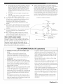
24
provides information with regard to proper grounding of the
mast and supporting structure, grounding of the leadqn wire
to an antmma discharge unit. size of grounding conductors.
location of autelma discharge unit. connection to grounding
electrodes, and requirements for the grounding electrode.
e)
If the product has been dropped or damaged in any
way, and
f)
When the product exhibits a distinct change in performance - this indicates a need for service.
Replacement Parts When replacement parts are required.
be sure the service technician has used replacement parts
specified by the mauulhctarer or haxe the same
characteristics as the original part. Unauthorized
substitutions may result in fire. electric shock, or other
hazards.
20
21
Safety Check Upon completion of any service or repairs to
this product, ask Ihe service lechuician 1(7perform safety
checks Io determine Ihal Ihe producl is in proper operating
condition.
22
Outdoor Antenna Grounding
If an outside antenna or
cable system is connected to the product, be sure the antmma
or cable system is grounded so as to provide some
protection against voltage surges and built-up static charges.
Article 810 of the National Electrical Code. ANSI/NFPA 70.
EXAMPLE
OF ANTENNA
GROUNDING
/-/
/
/
W:dl or Ceiling Mounting
The unit should be mounted
to a wall or ceiling only as recommended by the
manufacturer.
23
(NEC SECTION 810_0)
ELECTRIC
Heat The product should be situated away lrom heal
sources such as radiators, heat registers, stoves, or other
products (including amplifiers) that produce heat.
Note to CATV system
SERWCe
(NEC SECTION 810_1)
installer:
ELECTRODE SYSTEM
(NEC ART 25O PARTH)
This reminder is provided to call the CATV system
installer's attention to Article 820-40 of the NEC that
provides
guidelines
for proper
particular,
specifies
connected
to the grounding
grounding
that the cable
system
ground
NEC
NATIONAL ELECTRICALCODE
and, in
shall be
of the building,
as
close to the point of cable entry as practical.
FCC INFORMATION
1
IMPORTANT
NOTI(E:
DO NOT MODIFY
THIS
(for US customers)
Compliance with FCC regulations does not guarantee that
interference will not occur in all installations. If this
UNIT!
requiremmlts. Modifications not expressly approved by
Yamaha may void your authority, granted by the FCC. to
product is louud to he the source of interferm/ce, which
can be determined by turning the unit "OFF" and "ON".
please try to eliminate the problem by using one of the
following measures:
use the product.
IMPORTANT:
When connecting this product to
Relocate either this product or the device that is being
aflhcted by the interference.
accessories and/or another product use only high quality
shielded cables. Cahle/s supplied with this product MUST
be used. Follow all installation instructions. Failure to
Utilize power outlets that are on different branch (circuit
breaker or fllse) circuits or install AC line filter/s.
This product, when installed as indicated in the
instructions contained in this manual, meets FCC
folh)w instructions could void your FCC authorization
to
In the case of radio or TV interlerence, relocate/reorient
the antenna. If the antenna lead-in is 300 ohm ribbon lead.
use this product in the USA.
NOTE: This product has been tested and found to comply
with the requirements listed in FCC Regulations. Part 15
for Class "B" digital devices. Compliance with these
requirements provides a reasonable level of assurance that
your use of this product in a residential mwiroument will
not result in harmful interlhrence with other electronic
devices.
change the leadqn to coaxial type cable.
This equipment generates/uses radio frequencies and. if
not installed and used according to the instructions round
in the users manual, may cause interli_rence harmful to the
operation of other electronic devices.
The above statements apply" ONLY to those products
distributed by Yamaha Corporation of America or its
subsidiaries.
If these corrective measures do not produce satisfactory
results, please contact the local retailer authorized to
distribute this type of product. If you can not locate the
appropriate retailer, please contact Yamaha Electronics
Corp.. U.S.A. 6660 Orangethorpe Ave.. Buena Park. CA
90620.
Caution-ii
En
1
To assure the finest performance, please read this manual
carefully. Keep it in a sali_ place for future reli_rence.
2
Install this sound system in a well ventilated, cool. dry, clean
place away from direct sunlight, heat sources, vibration.
dust. moisture, and/or cold. Allow ventilation space of at least
30 cm on the top, 20 cm on the left and right, and 2(1cm on
the back of this unit.
3
Locate this unit away lrom other electrical appliances, motors.
or transformers to avoid hunlmiug
souuds.
4
Do not expose this unit to sudden temperature changes l?om
cold to hot. and do not locate this unit in an environment with
high humidity (i.e. a room with a humidifier) to prevent
condensation inside this unit. which may cause an electrical
shock, fire. damage to this unit. aud/or personal injury.
5
Avoid installing this unit where foreign objects may lall onto
this unit and/or this unit may be exposed to liquid dripping or
splashing. On the top of this unit. do not place:
other components, as they may cause damage aud/or
discoloration on the surface of this unit.
burning objects (i.e. candles), as they may cause fire.
damage to this unit. and/or personal injury.
containers with liquid in thmn. as they may f:dl and liqukl
may cause electrical shock to the user and/or damage to
this unit.
6
Do not cover this unit with a newspaper, tablecloth, curtain.
etc. in order not to obstruct heat radiation. If the temperature
inside this unit rises, it may cause fre. damage to this unit.
and/or personal il_jury.
7
Do not plug in this unit to a wall outlet until all connections
are complete.
8
Do not operate this unit upside-down. It may overheat.
possibly causing damage.
Do not use force on switches, knobs antVor cords.
9
10 When discmmecting the power cable from the wall outlet.
grasp the plug; do not pull the cable.
11 Do not clean this unit with chemical solvents: this might
damage the finish. Use a clean, dry cloth.
12 Only voltage specified on this unit must be used. Using this
unit with a higher voltage than specified is dangerous and may
cause lire, damage to this unit. and/or personal injury. Yamaha
will not be held responsible lk_rany damage resulting from use
of this unit with a voltage other than specified.
13 To prevent damage by lightning, keep the power cord and
outdoor antennas disconnected from a wall outlet or the unit
IS When not plamfiug to use this unit lor long periods of time
(i.e. vacation), disconnect the AC power plug l?om the wall
outlet.
16 Install this unit near the AC outlet and where the AC power
plug can be reached easily.
17 Be sure to read the "Troubleshooting" section on common
operating errors belbre concluding that this unit is l:mlty.
18 Before moving this unit, press MASTER ON/OFF to release it
outward to the OFF position to turn off this unit. and then
disconnect the AC power plug from the AC wall outlet.
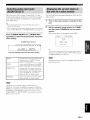
19 VOLTAGE SELECTOR (Asia and General models only)
The VOLTAGE SELECTOR on the rear panel of this unit
must be set for your local main voltage BEFORE plugging
into the AC wall outlet. Voltages are:
Asia model ............................ 22t)/230 241)V AC. 50/60 Hz
General model ........ 110/120/220/230 240 V AC. 51)/60 Hz
20 The balteries shall not be exposed to excessive heat such its
sunshine, fire or like.
WARNING
TO REDUCE THE RISK OF FIRE OR ELECTRIC
SHOCK, DO NOT EXPOSE THIS UNIT TO RAIN
OR MOISTURE.
As long as this unit is connected to the AC wall outlet,
it is not disconnected from the AC power source even
if you turn off this unit by MASTER ON/OFF. In this
state, this unit is designed to consume a very small
quantity of power.
FOR CANADIAN
CUSTOMERS
To prevent electric shock, match wide blade of ping to
wide slot and tully insert.
This Class B digital apparatus complies with Canadian
ICES-003.
POUR LES CONSOMMATEURS CANADIENS
Pour (viter les chocs (lectriques, introduire la htme la
plus large de la fiche dans la borne correspondante de
la prise et pousser jusqu'au fond.
Cet appareil numdrique de la classe Best conforme 5
la norme NMB-003 du Canada.
during a lightning storm.
14 Do not attempt to modil} or fix this unit. Contact qualified
Yamaha service persomlel when any service is needed. The
cabinet should never be opened lot any reasons.
Caution-iii
En
IMPORTANT
Please record the serial number of this unit in the space
below.
MODEL:
Serial No.:
The serial number is located on the rear of the unit.
Retain this Owner's Manual in a safe place for future
reference.
Notice .......................................................................
Features ...................................................................
2
3
Supplied accessories ..................................................
Getting started ........................................................
Quick start guide ....................................................
3
4
5
Connections
...........................................................
Optimizing
the speaker setting
for your listening room ....................................
Using AUTO SETUP ..............................................
11
28
28
Selecting the SCENE templates ...........................
33
Selecting the desired SCENE template .................... 33
Creating your original SCENE templates ................ 36
Playback ................................................................
37
Basic procedure .......................................................
37
Selecting the MULTI CH INPUT componeut ......... 38
Selecting the fi'ont speaker set ................................. 38
Selecting audiu input jacks (AUDIO SELECT) ...... 39
Displaying the current status of this unit
on a video monitur ...............................................
39
Using your headphones ............................................
40
Muting the audiu output ...........................................
4(I
Playing video suurces
in the background of an audiu source .................. 4(I
Displaying the input source infi_rnlatiun ................. 4(I
Using the sleep tinmr ...............................................
41
Sound field programs
..........................................
42
Selecting sound field programs ............................... 42
Sound field program descriptiuns ............................ 42
E_joying unprocessed input sources
(Straight decoding mode) .................................... 47
Using audio features .............................................
48
Enjoying pure hi-fi sound ........................................
48
Adjusting the tunal quality .......................................
48
Adjusting the speaker level ......................................
48
Enjoying multi-channel sources
in 2-channel stereo ...............................................
49
Selecting the night listening mude ........................... 49
FM/AM tuning ......................................................
5li
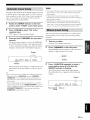
Automatic tuning .....................................................
50
Manual tuning ..........................................................
50
Automatic preset tuning ...........................................
51
Manual preset tuning ...............................................
51
Selecting preset stations ...........................................
52
Exchanging preset stations ......................................
52
XM Satellite Radio tuning ...................................
53
Connecting the XM Mini-Tuner Dock .................... 53
Actiw_ting XM Satellite Radio ................................ 54
Basic XM Satellite Radio uperatiuus ....................... 54
Setting the XM Satellite Radio preset channels ...... 56
Displaying the XM Satellite Radio informatiun ...... 57
Using iPod TM ..........................................................
58
Controlling iPud r:'l...................................................
58
Recording ..............................................................
60
Advanced
sound configurations
...........................
Clmnging sound fieM parameter settings .................
Selecting decuders ...................................................
Customizing
this unit (MANUAL SETUP) .........
Using SET MENU ...................................................
1 SOUND MENU ....................................................
2 INPUT MENU ......................................................
3 OPTION MENU ...................................................
Remote control features ........................................
61
61
66
69
71
72
78
81
85
Using the rmnote control for the SCENE l_ature .... 85
Cuntrolling this unit. a TV, or other components.... 86
Setting rcmute control codes ................................... 88
Resetting all remote control codes ........................... 89
Using multi-zone
configuration
............................
90
Cunnecting Zone 2...................................................
90
Controlling Zone 2 ...................................................
91
Advanced
setup ......................................................
93
Using the advanced setup ........................................
93
Troubleshooting
.....................................................
Resetting the system ............................................
Glossary ................................................................
Sound field program information
......................
Parametric
equalizer information
.....................
Specifications
.......................................................
Index .....................................................................
97
104
105
107
108
109
111
(at the end of this manual)
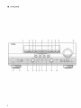
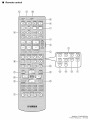
Front panel ................................................................
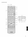
Remote control .......................................................
i
ii
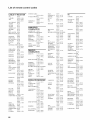
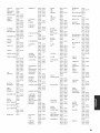
List of remote
iii
"@SPEAKER"
control
codes .................................
ur "(_) DVD" (exalnple) indicates the name
of the parts on the lront panel ur the remote controh Refer to
the attached sheet or the pages at the end uf this manual for
the inl_nnatiun about each position of the parts.
1En
11
About
this manual
• .-',;2indicates a tip fl)r _our operation.
• Some operations c:m be perlormed by using either the
buttons on the front panel or the ones on the remote
controh In case the button ((ames difli:r between the l?ont
panel and the remote control, the buttol( name on the
remote control is give(( in parentheses.
• This manual is printed prior to production. Design and
specifications are suhject to change in part as a result of
improvements, etc. In case of difli:rences between the
manual and product, the product has priority.
• "@SPEAKER"
or "@DVD" (example) indicates the
nauru of the parts on the li'ont panel or the remote controh
Refer to the attached sheet or the pages at the eud of this
manual for the information about each position of the
parts.
• The symbol "_,* " with page number(s) indicates the
corresponding rel'crence page(s).
We Want You Listening For A Lifetime
rl0_
DiGiTAL.
Manulactured under license lrom Dolby Laboratories.
"Dolby". "Pro Logic", and Ihe double-D symbol are trademarks
of Dolby Laboralories.
DTS_ES [NEO:6 ]96/24. Product "DTS" and "DTS-ES ]NEO:6"
are registered trademarks of DTS. Inc.
"96/24" is a trademark of DTS. Inc.
iPod
TM
"(Pod" is a trademark of Apple Inc., registered in the U.S. and
other countries.
"HDMI". the "HDMI" log() and "High-Deliuition Multimedia
lnterli_ce" are trademarks or registered trademarks of HDMI
Licensing LLC.
SILENT
CINEMA
Consmner Electronics Group want you to get the
most out and
of yo_.trequipment
by playingAssociation's
it at a safe
_alnaha
the Electrouic Industries
v,,
level. One that lets the sound come through loud and
I¢_!ST_}N_ clear without annoying blaring or distortion
and,
most ilnportantly, without affecting yottr sensitive
hearing. Since hearing damage from loud so(rods is often
undetectable tmtil it is too late. Yamaha and the Electronic
Industries Association's Consumer Electronics Group
reconnnend you to avoid prolonged exposure from excessive
_ohune levels.
EX
TM
"SILENT CINEMA" is a trademark of YAMAHA
CORPORATION.
XMMini.Tun r
The XM name :rod related logos are registered trademarks of XM
Satellite Radio Inc.
neurai
SO_OUNO
Neural Surround r_l name aud rehlted logos are tradmimrks owued
by Neural Audio Corporation.
2 En
Built-in 7-channel power amplifier
HDMI (High-Definition
•
•
Minimum
RMS
output
pol_rer
(20 Hz to 20 kHz. 0.069_
Fronl: 105 W + 105 W
Center:
THD.
8 _-2)
•
105 W + 105 W
Surround
back:
18 preset
4 original
•
Controlling
Yamaha
component
flmction
(some
SCENE
templates
SCENE
for _ariuus
templates
SCENE
models
control
only)
•
Proprietary
fields
Yamaha
signal
working
•
Conlpressed
Music
technology
•
with the SCENE
to improve
capabilily
>
of sound
DOCK
terlniual
1(3connect
(such
as the YDSd0.
(Click
and Wheel),
•
Playback
•
Battery
OSD
DTS 96124 decoder
•
•
Neural
Surround
•
Virtual
CINEMA
•
SILENT
tile sound
as tile MP3
II/Dolby
lk)rulat) to
Pro Logic
llx
40_station
randonl
Aulonlalic
preset
•
Preset
slaliou
and direct
preset
tuning
tuning
shifting
capability
(preset
editing)
XM Satellite Radio
XM Satellite
Radio
Tuner
sold separately)
Neural
Dock"
Surround
XM Satellite
XM Satellite
Check
decoder
Radio
a full Sllrrouud
tuning
(NTSC)/
tile "XM
ira multi-chalmels,
(on-screen
displaying
which
dock
supports
iPod
Optimizer)
for
capability
S-video
signal
•
Component
video
(3 COMPONENT
•
Digital
of
in
component
menus
individu:d
additional
•
video
Room
Acoustic
setup
converter
display)
input
iuput/outpul
thai allow you to optimize
audiovisual
input jacks
syslem
Ik)r discrete
signal
conversion
video)
:rod coaxial
(conll_osite
capabilily
lor monitor
OUT)
+4- S-video
out
•
Pure Direct mode for pure hiq'i sound for all sources
•
Cinema
and music
•
Remote
control
•
•
Zone
Zone
2 cuslom installation
sv¢ilching capability
using
ZONE CONTROL
Bi-amplificalion
•
Sleep
:radio
videu
Optical
•
digital
night listening
with preset
connection
multi-
capability
inpul/oulput
capahilily
includes
VIDEO INs :rod 1 MONITOR
•
Mini-
resulting
iPod univers:d
remote
facilily
between
signal jacks
modes
control
codes
capability
Ihe main zone and Zone 2
capability
timer
experience
information
that you received
displaying
all of the t_llowing
Remote control
_
(using
to play back the XM HD couleul
broadcasts
souud
Radio
capahility
a Y:unaha
Pal'ametric
5.1 or 7. l-channel
>
FM/AM tuner
•
(Yamaha
channel
DSP
CINEMA
•
(480i
or 1080i)
iPod nano, and iPod mini
this unit to suit your
decoder
Sophisticated
HDMI
Other features
•
Pro Logic
>
capability
•
Dolby Pro Logic/Dolby
decoder
video
out
sold separately),
ilfformalion
charging
Ihal of a high-quality
stere()
Dolby Digilal/Dolby
Digital EX decoder
DTS/DTS-ES
Matrix. Discrete. DTS Neo:6.
(such
1.2a
up-conversion
up-scaling
,'-720p
as well as
version
+4- component
and/or
480p/576p
,'-tutomalic speaker
192-kHz/24-bi/D/A
artifacts
video
lor monitor
video deiulerlacing
YPAO
of compression
•
•
video +4- S-video
videu)
•
quality
mode
digital
transmission)
on HDMI
iPod controlling capability
capability
support
for tile cre:llion
Enhancer
signal
audio based
Interface)
or high-definition
situations
lk)r customizing
Sound field programs
•
Io HDMI
Analog
enhanced
video
Analog
576i (PAL)
•
]080p
digilal
digital
•
•
•
(includes
video
Multimedia
lbr standard,
multi-channel
(composile
105 W + 105 W
SCENE function
•
•
inlerhtce
video
105 W
Surround:
HDMI
capability
parts.
Batteries (2)
AM loop antenna
(AA, R6, UM-3)
Optimizer
microphone
Indoor FM antenna
0000
The form of the supplied accessories varies depending on tile models.
3 En
•
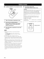
Installing batteries in the remote control
•
VOLTAGE SELECTOR
(Asia and General models only)
Caution
The VOLTAGE
SELECTOR
on the rear panel of this
unit must be set for your local voltage BEFORE
plugging the power cable into the AC wall outlet.
hnproper setting
cause damage
hazard.
of the VOLTAGE
Rotate the VOLTAGE
counterclockwise
straight
1
Take off the battery compartment
2
Insert the two supplied batteries
(AA, R6, UM-3) according to the polarity
markings (+ and -) on the inside of the
battery compartment.
cover.
cover back
• Change all of the batteries if you notice the following
conditions:
the operation range of the remote control decreases.
the @TRANSMIT indicator does not llash or its light
becomes dim.
• Do not use an old battery together with a new one.
• Do not use dilTcrent types of batteries (such as alkaline and
manganese batteries) together. Read the packaging carelully as
these dilTerent types of batteries may have the same shape and
color.
• lfthe batteries have leaked, dispose of them immediately. Avoid
touching the leaked material or letting it come into contact with
ch)thing, etc. Clean the battery compartment thoroughly befl)re
installing new batteries.
• Do not throw away batteries with general house waste: dispose
of them correctly in accordance with your local regulations.
• If the remote control is without batteries lot more than 2
minutes, or if exhausted batteries remain in the rmnote control.
the c()ntents of the memory may be cleared. When the memory
is cleared, insert new batteries, set up the rmnote control code
and program any acquired functions that may have been
cleared.
4 En
SELECTOR
to the correct
may
a potential
clockwise
position
fire
or
using a
slot screwdriver.
Voltages are as follows:
Asia model ...................
General model
.....................
Snap the battery compartment
into place.
SELECTOR
to this unit and create
220/230-240
110/120/220/230-240
V AC, 50/60
Hz
V AC, 50/60
Hz
VOLTAGE
SELECTOR
Voltage
indication
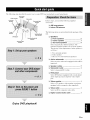
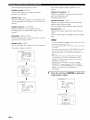
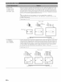
Tile following steps describe the easiest way to enjoy DVD movie playback in your home theater.
Video
monitor
Front right
speaker
Subwoofer
In these steps, you need the following supplied
accessories.
[71AM loop antenna
[71Indoor FM antenna
The following items are not included in the package of this
unit.
Surround left
speaker
Speakers
[71Front speakers .................................... 2
[71Center speaker ................................... 1
[71Surround speakers ............................. 4
Select magnetically shielded speakers. The
minimum required speakers are two front speakers.
The priority of the requirement of other speakers is
as follows:
1. Two surround speakers
2. Center speaker
3. One (or two) surround back speaker(s)
[71Active subwoofer
....................................
1
Select an active subwoofer equipped with an RCA
input jack.
[71Speaker cables ........................................
[71Subwoofer cable .....................................
Select ;t monaural RCA cable.
7
1
[71DVD player ...............................................
1
Select DVD player equipped "adth coaxial digital
andio output jack and composite video output
jack.
Video monitor
...........................................
1
Select a TV monitor, video monitor or proiector
equipped with a composite video input jack.
CI Video cable
..............................................
1
Select an RCA composite video cable.
[71Digital coaxial audio cable .....................
1
Enjoy DVD playback!
SEn
Ifp_T_,_-;.
a.lqi'; i-
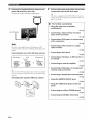
Place your speakers
unit.
in the room and connect
them to this
Be sure to connect
the left channel
(R), "+" (red) and "-" (black)
Front
I
speakers
oosen
and center
Insert
(L), right channel
properly.
speaker
/
Tighten
1
"N
1
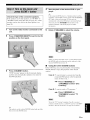
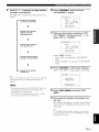
Place your speakers and subwoofer in the
room.
2
Connect speaker cables to each speaker.
To the center speaker
\
To the front left
speaker
Front right speaker
Surround and surround back speakers
Be sure to connect the "+" (red) and .... (black) properly.
Cables are colored or shaped differently, perhaps with a
stripe, groove or ridge. Connect the striped (grooved, etc.)
cable to the "+" (red) terminals of this unit and your speaker.
Connect the plain cable to the .... (black) terminals.
3
Connect each speaker cable to the
corresponding speaker terminal of this unit.
f
right speaker
back
To the surround
left speaker
@
Make
sure that this unit and the subwoofer
unplugged
@
to prevent
wires of the speaker
Connect
the subwoofer
SUBWOOFER
from the AC wall outlets.
Twist the exposed
together
are
cables
cable
Subwoofer
Do not let the bare speaker
wires touch each other.
@
Do not let the bare speaker
wires tonch
to the
PRE OUT jack of this unit and
the input jack of the subwoofer.
short circuits.
@
left speaker
To the surround
back right speaker
AV receiver
any metal
part of this nnit.
Inputjack
_
Subwoofer
cable
SUBWOOFER
6En
PRE OUT jack
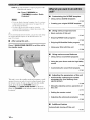
Connect the video cable to the composite
video output jack of your DVD player and
DVD VIDEO jack of this unit.
AV receiver
DVD player
DVD VIDEO jack
Make
sure that this unit and the DVD
player are unphigged
wall ontlets.
from the AC
Composite video
output jack
3
Connect the digital coaxial audio cable to the
digital coaxial audio output jack of your DVD
player and the DVD DIGITAL INPUT COAXIAL
jack of this unit.
DVD player
Video
cable
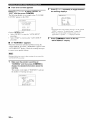
Connect the video cable to the VIDEO
MONITOR OUT jack of this unit and the video
input jack of your video monitor.
Video monitor
AV receiver
AV receiver
Video
input jack
Video
Digital coaxial
audio output
jack
Digital coaxial
cable
VIDEO MONITOR
OUT jack
audio
DVD DIGITAL INPUT
COAXIAL jack
7 En
Ifp_T_,_-r.
a.l. fi';i-
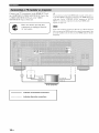
Connect the supplied AM loop antenna and
indoor FM antenna to this unit.
Connect the power plug of this unit and other
See page 24 for tile connection information.
-'#Thisunit is equipped with AC OUTLET(S) lot the power
components
AM loop antenna
©
into the AC wall outlet.
supply of the other components (except Korea model). See
page 24 for details.
•
•
For further
connections
Using the other kind of speaker
combinations
_,_ P. 12
Indoor
FM antenna
I
•
Connecting a video monitor via various
ways of the connection
•
Connecting a DVD player via various ways
of the connection
_
_
•
The types of the supplied indoor FM antenna and FM
antemm terminal of this unit are different depending on the
models.
Connecting the wire of the AM loop antenna
Open the lever
Insert
Close the lever
•
•
P. 19
Connecting a DVD recorder or a digital
video recorder
Connecting
Connecting
a turntable
_
P. 20
_
P. 20
a set-top box
a CD player, an MD recorder or
_
•
P. 18
Connecting
P. 21
an external amplifier
_,_ P. 22
The wire of the AM loop antenna does not have any polarity
and you can connect either end of the wire to AM or GND
terminah
•
Connecting a DVD player via analog multichannel audio connection
•
Connecting
•
Using the REMOTE IN/OUT jacks
•
Using the VIDEO AUX jacks on the front
panel
_
Assembling the supplied AM loop antenna
_
P. 23
_
R 23
_
•
•
SEn
Connecting
P. 22
a Yamaha iPod universal dock
P. 23
an outdoor FM/AM antenna
_
P. 24
_
P. 53
Connecting the XM Mini-Tuner Dock
Start
playback
of the desired
DVD on your
player.
tf the connected DVD pla_er is a Y:mmha product :rodhas
capahilit_ of the SCENE control signals with the REMOTE
OUT jack of this unit (see page 23), this unit can
automatically activate the DVD player and start playback
Check the type of the connected speakers.
If the speakers are 6 ohm speakers, set "SP IMR" to
"6_Q MIN" before using this unit (see page 25). 4 ohm
speakers can be also used as the front speakers (see
page 94).
1
Turn on the video monitor connected to this
unit.
2
Press @MASTER
ON/OFF
when you press the @)SCENE1 button. Refer to the
instruction manual of the DVD player lor fimher
inlonnation.
5
Rotate @VOLUME
to adjust the volume.
inward to the ON
position on the front panel.
When you change the input source or sound field progran].
the SCENE mode is deactivated, and the indicator on the
selected SCENE button turns ofl.
•
3
Using the other SCENE buttons
In tile following cases, try pressing tile corresponding
SCENE button to enjoy the playback of the desired
Press
@SCENE1
"DVD Viewing"
button.
appears
and this unit automatically
sources.
in the front panel display,
optimize
own status
for
the DVD playback.
Case A: "I want to listen to a music disc from the
connected DVD player as the background
music I\_r this room..."
Press @SCENE2
(or
@SCENE2)
to select "Disc
Listening".
Case B: "I want to watch a TV program..."
Press @SCENE3
(or
@SCENE3)
to select "TV
Viewing".
To use the "TV Viewing" template (Case B), you must
connect a satellite receiver, a cable TV receiver or an HDTV
decoder to this unit in advance. See page 20 lot details.
The indicator on the selected SCENE button lights up while
this unit is in the SCENE mode.
9En
Ifp_T_,_-r.
a.lqi'; i-
Case C: "1 want to listen to a mnsic program of the
FM/AM radio station..."
Press @SCENE4
(or
®SCENE4)
to select "Radio
Listening".
•
•
Customizing
the SCENE
templates
Using various SCENE templates
r,_ p. 33
• To use the "Radio Listening" template (Case C), you have
to tune into the desired radio station. See pages 50 to 52
for the tuning information.
• To achieve the best possible reception, orient the
connected AM loop antenna, or a@lst the position of the
end of the indoor FM antemm.
--'4¢-If you catmot find the desired situation, you can select and change
the assigned SCENE template lor the SCENE buttons. See
page 33 for details.
•
•
Creating your original SCENE templates
_._ P. 36
•
Using various input sources
• Basic controls of this unit
r_ p. 37
•
Enjoying FM/AM radio programs
_._ P. 50
After using this unit...
•
Press @MAIN
ZONE
ON/OFF
Enjoying XM Satellite
Radio programs
to set this unit to
•
the standby mode.
•
•
_
P. 53
_
P. 58
_
P. 42
Using your iPod with this unit
Using various
sound
features
Using various sound field programs
•
Using the pure direct mode for high fidelity
sound
•
Customizing
_
P. 48
the sound field programs
r_ p. 61
•
This unit is set to the standby
amount
of power
the remote
in order
control.
to receive
infrared
signals
on the remote
control).
of this unit
Automatically optimizing the speaker
parameters for your listening room
(AUTO SETUP)
_-_ P. 28
•
Manually adjusting various parameters of
this unit
•
Setting the remote control
•
Adjusting the advanced parameters
from
@SCENE
buttons (or
ZONE ON/OFF on the front
the parameters
•
a small
To turn on this unit from the standby
mode, press the desired
@SCENE)
or @MAIN
panel (or @POWER
for details.
mode and consumes
Adjusting
See page 25
_
P. 71
_
P. 85
r._ p. 93
•
Additional
Automatically
feature
turning off this unit
_.> P. 41
10 En
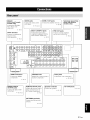
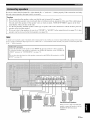
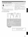
_XM jack
.....
(U.S.A. and Canada
models only)
Connect the XM MiniTuner Dock (sold
separalely).
R 53
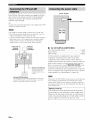
CH INPUT jacks
t the input source
lent equipped with the
lannel otltptll jacks.
DOCK terminal
Connect a Y:mmha iPod
universal dock
(sold separately).
P. 23
_umo
ii_@@@@@@@@@@
o®®®®®®®®®®
,°
j ......:=,
®8®®®®®
oo[
I
I
)B
_l_
('i'iD M_ connectors
/Connect the HDMI
OUT
®
Outputs the control signals to
external conlponenls.
colnpone//ls.
P. 16
_'_._£
INPUT/
OUTPUT jacks
Connecl the digital audio
cable plugs.
")
REMOTE IN/OUT jacks
I
I
input and output jacks ol
'onnecl
tile
tile
Yanlaha
renlole
COlllrO]
components.
R 23
IAC OUTLET(S)
R 24" /
ANTENNA terminals
Connect the FM and AM
antenna.
_, P. 24
11 En
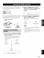
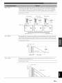
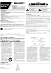
[[¶'tlfl[_'_ffql_
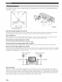
The speaker layout below sllows the speaker
channel audio sources.
setting
we recommend.
You can use it to enjoy CINEMA
DSP and multi-
\
,
/
30 cm (12 in) or more
Front
left and right speakers
The front speakers
speaker
The center speaker
center speaker,
Surround
Surround
is for the center channel
speakers
The surround
Presence
right
left and
speakers
and surround
speakers
speakers
supplement
to "PRESENCE"
(SBL
vocals,
etc.). If for some reason
are obtained
it is not practical
to use a
with the full system.
sounds.
and SBR)
the surround
speakers
and provide
more realistic
front-to-back
transitions.
(PL and PR)
the sound from the front speakers
(see page 42). To use the presence
SP ASSIGN"
(dialog,
however,
(Sk and SR)
supplement
left and right
sounds
it. Best results,
are used for effect
back speakers
The presence
from the
(C)
you can do without
back
z_tan equal distance
The distance of each speaker from each side of the video monitor should be the same.
left and right speakers
The surround
programs
(FL and FR)
are used for tile main source sotmd plus effect sounds. Place these speakers
ideal listening position.
Center
1.8 m (6 ft)
(see pages
speakers,
connect
with extra ambient
the speakers
to EXTRA
effects
produced
SP terminals
by the sound field
and then set "EXTRA
29 and 72).
0.5 tolm(lto3ft)
H............=...._
0.5 to 1 m (1 to 3 ft)
H..........=......_
i
1.8 m (6 ft)
Subwoofer
(SW)
The use of a snbvvoofer
effective
with a built-in
not only for reinforcing
of the LFE (low-frequency
not so critical,
speakers.
12 En
1.8 m (6 ft)
because
Turn it slightly
effect)
channel
low bass sounds
toward
amplifier,
such as the Yamaha
bass frequencies
included
Active
from any or all channels,
in Dolby Digital
are not highly
Servo Processing
Subwoofer
but also for high fidelity
and DTS sources.
directional.
But it is better
the center of the room to reduce
wall reflections.
The position
System,
sound
is
reproduction
of the subwoofer
to place the subwoofer
near the front
is
Be sure to connect the left channel (L), right channel (R), "+" (red) and
this unit cannot reproduce the input sources accurately.
(black) properly. If the connections are faulty,
....
Caution
•
Before connecting
•
Do not let the bare speaker
this unit and/or
panel display
•
the speakers.
If the speaker
off (see page 25).
wires are short-circuited,
"CHECK
SP WIRES"
appears
in the front
shielded
speakers.
If this type of speaker
still creates
interference
with the monitor,
place the
away from the monitor.
If you are to use 6 ohm speakers,
speakers
make sure that this unit is turned
wires touch each other or let them touch any metal part of this unit. This coukt damage
when you turn on this unit.
Use the magnetically
speakers
•
the speakers,
be sure to set "SP IMR" to "6f.) MIN"
can be also used as the front speakers
before
using this unit (see page 25). 4 ohm
(see page 94).
A speaker c®rd is actually a pail" of insulated cables running side by side. Cables are col®red ®r shaped differenlly, perhaps with a stripe,
gr®®ve or ridge. C®nnecl the striped (gro®ved, etc.) cable Il! the "+" (red) terminals ®f Ihis unit and your speaker. Connect the plain cable
t®the .... (black) terminals.
EXTRA SP terminals
Connect the alternative li'ont speaker system (FRONT B), presence speakers or Zone 2 speakers.
To select the Rmction of the speakers connected to the EXTRA SP terminals, set the "EXTRA SP
ASSIGN" parameter ill "SOUND MENU" (see page 72).
Subwoofer
-"4;'You call also select the function of the speakers connected to the EXTRA SP terminals in "AUTO
SETUP" (see page 29).
Center ea er
Right
Left
Surround back speakers
Right
Left
Surround speakers
Right
Left
Front speakers
(FRONT A)
When you use a single surround back
speaker,c®nnectthe speaker to the lell
SURROUND BACKterminal
(SINGLE).
13 En
•
Connecting the speaker cable
Remove approximately 10 mm (0.4 in) of
insulation from the end of each speaker
cable and then twist the exposed wires of the
cable together to prevent short circuits.
2
•
Connecting the banana plug
(except Europe, Asia and Korea models)
Tighten the knob and then insert the banana plug
connector into the end of the corresponding
terminal.
Loosen the knob.
Bed: positive
Black: negative
•
Bed: positive
Black:
(-)
connections
Caution
Remove the shorting bars or bridges of your speakers
to separate the LPF (low pass filter) and HPF (high
pass filter) crossovers.
(+)
negative
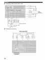
Using bi-amplification
(+)
(-)
Insert one bare wire into the hole on the side
of each terminal.
This unit allows you to make bi-amplification connections
to one speaker system. Check if your speakers support biamplification.
To make the bi-amplification connections, use the FRONT
and SURROUND BACK/BI-AMP terminals as shown
below. To activate the bi-amplification connections, set
"BI-AMP" to "ON" in "ADVANCED SETUP" (see
page 96).
Front speakers
Right
4
Left
Tighten the knob to secure the wire.
When you make the conventional connection, make sure tllat the
shorting bars are put into the terminals appropriately. Refer Io tile
instruction manuals ol the speakers for details.
14 En
.qlflI_gqP
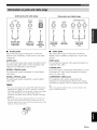
Audio jacks and cable plugs
AUDIO
©
®
©©
t t
(White)
DIGITAL
COAX,AL
OPTICAL
COMPONENTVIDEO
VIDEO
S VIDEO
Y
t
Coaxial
digital audio
cable plug
Optical
digital
audio cable
plug
Audio jacks
F_
Pn
© @©oo
(Yellow)
(Orange)
Left and right
analog audio
cable plugs
•
DIGITAL
©
t
(Red)
Video jacks and cable plugs
(Green)
(Blue)
(Red)
t
t
t t t
Composite
video cable
plug
S-video
cable plug
Component
video cable
plugs
Y f
components.
•
Video jacks
This unit hits three types of video jacks. Connection
depends on the availability of input jacks on your video
monitor.
AUDIO
VIDEO
This unit has three
depends
types of audio jacks.
on the availability
of audio jacks
Connection
on your other
jacks
For conventional
and right analog
analog audio signals transmitted
via left
audio cables. Connect red plugs to the
right jacks
and white plugs to the left jacks.
DIGITAL
COAXIAL
DIGITAL
OPTICAL
transmitted
For S-video
via coaxial
digital
via optical
digital
jacks
For digital audio signals
:radio cables.
transmitted
For conventional
composite
composite video cables.
S VIDEO
jacks
For digital audio signals
audio cables.
jacks
transmitted
via
jacks
signals,
separated
into the lumin:mce
chrominance
(C) video signals
wires of S-video cables.
COMPONENT
• You can use the digital jacks to input PCM. Dolby Digital and
DTS bitstreams. When you connect components to both the
COAXIAL and OPTICAL jacks, priority is given to the signals
input at the COAXIAL jack. All digital input jacks are
compatible with digital signals with up to 96 kHz of sampling
lbequency.
• Pull out the cap fi'om the optical jack before you connect the
fiber optic cable. Do not discard the cap. When you are not
using the optical .jack. be sure to put the cap back in place. This
cap protects the.jack lrom dust.
video signals
For component
VIDEO
transmitted
(Y) and
on separate
jacks
video signals,
luminance
(Y) and chrominance
transmitted
on separate
separated
into the
(Pro PIO video signals
wires of component
video cables.
"4C-Thisunit
is equipped with the video conversion fimction. See
pages 17 and 82 lot details.
1hEn
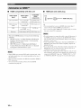
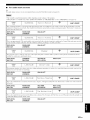
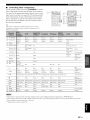
HDMI compatibility with this unit
Audio signal
types
Audio signal
formats
2ch Linear PCM
2ch. 32-192 kHz.
16/20/24 bit
CD. DVD-Video.
DVD_Audio. etc.
Multi-ch Linear
PCM
8ch. 32_192 kHz.
16/20/24 bit
DVD_Audio. etc.
DSD
2/5. Ich.
2.8224 MHz. I bit
SAC[). etc.
Dolby Digital. DTS
DVD-Video. etc.
Bitstream
Compatible
HDMI
components
HDMI jack and cable plug
HDMI
HDMI cable plug
• We recommend that you use an HDMI cable shorter than 5
meters ( 16 feet) with the HDMI logo printed on it.
• Use a conversion cable (HDMI jack <_- DVI-D jack) to connect
this unit to other DVI components.
This unit's HDMI interface is based on the following
standards:
• HDMI Version 1.2a (High-Definition Multimedia
Interface Specification Version 1.2a) licensed by
HDMI Licensing, LLC.
• HDCP Revision 1.1 (High-bandwidth Digital
Content Protection System Revision 1.1) licensed
by Digital Content Protection, LLC.
• When CPPM copy-protected DVD audio is played back. video
and audio signals may not be output depending on the type of
the DVD player.
• This unit is not compatible with HDCP-incompatible HDMI or
DV] components.
• You can check the potential problem about the HDMI
connection (see page 41 ).
16 En
•
• Do not disconnect or connect the cable or turn off the power of
the HDMI components connected to the HDMI OUT jack of
this unit while data is being transli_rred. Doing so may disrupt
playback or cause noise.
• Audio signals input at input jacks other than the HDMI IN 1 or
HDMI IN 2 jack of this unit cannot be digitally output at the
HDMI OUT jack.
• If you turn ofl the power of the video monitor connected to the
HDMI OUT jack via a DVI connection, this unit may li/il to
establish the connection to the component.
• The analog video signals input at the composite video. S-video
arid component video jacks can be digitally up-converted to be
output at the HDMI OUT jack. Set "VIDEO CONV." to "ON"
in "MANUAL SETUP" (see page 81) to activate this feature.
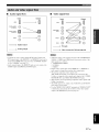
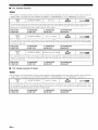
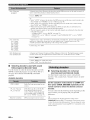
Audio signal flow
•
Input
Video signal flow
Output
Input
HDMI
HDMI
©
DIGITAL AUDIO
(COAXIAL)
DIGITAL
Output
COMPONENT
VIDEO
AUDIO
(OPTICAL)
AUDIO
SVIDEO
VIDEO
--._
Digital
_
<_
output
-_ Through
......
b_ Analog
• 2-cham_el
input at the HDMI
at the HDMI
is Net to "OTHER"
• Audio signals
AUDIO
---m-
as well as multi-chamlcl
DTS signals
output
output
output
OUT.jack
PCM.
Dolby
IN 1 or HDMI
only when
Digital
and
IN 2jack
"SUPPORT
CaD be
AUDIO"
(Nee page 77).
input at the HDMI
and DIGITAL
IN jacks
OUTPUT
arc not output
jacks.
at the
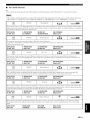
Video conversion ON (see page 82)
• When the analog video signals are input at the COMPONENT
VIDEO, S VIDEO and VIDE() jacks, the priority order of the
input signals iNaN fl)IIGws:
1. COMPONENT VIDEO
2. S VIDE()
3. VIDEO
• Digital video signals input at the HDMI IN 1 or HDMI IN 2
.jack CmmGtbe output lrom analog video output.jacks.
• The analog component video signals with
480i (NTSC)/576i (PAL) of resolution are converted to the
S-video or composite video signals and output at the S VIDE()
MONITOR OUT and VIDEO MONITOR OUT jacks.
• This trait clods not accept analog component video signals with
1080p of resolutiGn.
• The OSD signal iNnot output at the VCR OUT and DVR OUT
jacks and iN not recorded.
• Use the "HDMI UP-SCALING" parameter in "DISPLAY SET"
to deinterlace add convert the resolution of the video signals
output at the HDMI OUT.jack (see page 81).
17En
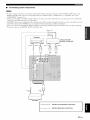
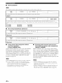
Connect
your TV (or proiector)
the COMPONENT
S VIDEO
MONITOR
VIDEO
MONITOR
to the HDMI
MONITOR
OUT jack,
OUT jacks,
the
OUT jack or the VIDEO
OUT jack of this unit.
You can choose to play back HDMI audio signals on this unit or
on another HDMI component connected to the HDMI OUT jack
of this unit. Use the "SUPPORT AUDIO" parameter in "SOUND
MENU" to select the component to play back HDMI audio
signals (see page 77).
Make sure that this unit and other
components
are unplngged
AC wall outlets.
from the
Some video monitors connecled to this unit via a DVI conneclion
fail to recognize the HDMI audio/video signals being input if they'
are in the slandby mode. In Ihis case. the HDMI indicalor flashes
irregularly.
IS-video in
video in
Componenl
HDMI in
]Vide() in
TV (or projector)
18
En
indicates
recommended
indicates
alternative
connections
connections
i
.qfff[_{|°tP
I
_1_
J
components
are unplugged from the
AC wall outlets.
Make sure that this unit and other
[
• When "VIDEO CONV." is set to "OFF" (see page 82), be sure
to make the same type of video connections as those made lk_r
your TV (see page 18). For example, if you connected your TV
to the VIDE() MONITOR OUT .jack of this unit. connect your
other components to the VIDE() jacks.
•
• When "VIDEO CONV." is set to "ON" (see page 82), the
converted video signals are output only at the MONITOR OUT
jacks. To record a source, make the same type of video
com]ections between each component.
• To make a digital commction to a componeut other than the
delhult component assigned to each DIGITAL INPUT or
DIGITAL OUTPUT jack, select the corresponding setting for
"OPTICAL OUT". "OPTICAL IN". or "COAXIAL IN" in "110
ASSIGNMENT" (see page 78).
• If you cmmect your DVD player to both the DIGITAL INPUT
(OPTICAL) and the DIGITAL INPUT (COAXIAL)jacks.
priority is given to the signals input at the DIGITAL INPUT
(COAXIAL) jack.
Connecting a DVD player
Coaxial out
Optical out /
HDkII ou,_
DVD player
S-video out
:_Video out
1
)tll
............
indicates
recommended
indicates
alternative
connections
connections
19 En
•
Connecting a DVD recorder, PVR or VCR
DVD recorder,
PVR
Audio oul
Connecting a set-top box
Satellite receiver, cable TV
receiver or HDTV decoder
©
20 En
.qlflf_1_|qff
•
Connecting audio components
• To make a digital comeection to a component other than the def:mlt component assigned to each the DIGITAL INPUT jack or the
DIGITAL OUTPUT jack. select the corresponding setting lot "OPTICAL OUT". "OPTICAL IN". or "COAXIAL IN" in "I/O
ASSIGNMENT" (see page 78).
• Commct your turntable to the GND terminal of this unit to reduce noise in the signah However, you may hear less noise without the
c(mnection to the GND terminal lor some turntables.
• The PHONO jacks are only compatible with a turntable with ale MM or a high<mtput MC cartridge. To connect a turntable with a lowoutput MC cartridge to the PHONO jacks, use ale inqine boosting transformer or an MC_head amplifier.
• When you connect both the DIGITAL INPUT (OPTICAL)jack and the DIGITAL INPUT (COAXIAL)jack to an audio component.
the priority is given to the DIGITAL INPUT (COAXIAL).jack.
Optical out
Oplic:d in
e..........
............
_
,,ound
I
• )u7
Audio
ou
uu
C() axial
_
(
_vfl
I
[
/
\
_
1 rec°rder
"
Ii(
A;',
AA
5JE,
_÷"U
LL R
_ _
5J Lit,
9 U
2
°r tape deck
2'd"
AA
Audio
CD recorder, MD
in
,
CD player
indicates
recommended
indicates
alternative
connections
connections
21 En
•
Connecting an external amplifier
This unit has more than enough
or if you want to use another
the same channel
signals
po'a, er for any home
amplifier,
connect
as the corresponding
use. However.
an external
SPEAKERS
if you want to add more power to the speaker
amplifier
to the PRE OUT jacks.
ontput
Each PRE OUT jack outputs
terminals.
Notes
•
•
•
•
When you make connections to the PRE OUT jacks, do not make connections to the SPEAKERS terminals.
The signals output at the FRONT PRE OUT jacks are al'li:cted by the TONE CONTROL settings (see page 48).
A;ljust the vohnne level of the subwooli:r with the control on the subwoofcr (see page 48).
Some signals may not be output at the SUBWOOFER PRE OUT jack depending on the settings for "SPEAKER SET" (see page 72)
and "LFE/BASS OUT" (see page 72).
SUR.BACK
@
Surround
connect
one external
channel,
connect
jacks
output jacks.
amplifier
When
you only
for the surround
it to the SINGLE
back
jack.
• When "BbAMP" is set to "ON'. this unit outputs the front
channel audio signals at the SUR.BACK PRE OUT.jacks.
• The audio signals output at the SUR.BACK PRE OUT jacks
differ depending on the "EXTRA SP ASSIGN" setting (see
page 72).
@ FRONT PRE OUT jacks
Front channel output jacks.
SUBWOOFER
@
@ SURROUND PRE OUT jacks
Surround channel output jacks.
Connect
a subwoofer
CENTER
@
Center
•
PRE OUT
back channel
PRE OUT jack
with a built-in
amplifier.
PRE OUT jack
channel
output
jack.
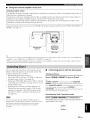
Connecting a multi-format player or an external decoder
This unit ts equipped
SUBWOOFER)
w,ith 6 additional
for discrete
input jacks (left and right FRONT,
multi-channel
input from a nmlti-format
CENTER,
player, external
left and right SURROUND
decoder,
sound processor
and
or pre-
anaplifier.
If you set "INPUT
in "MULTI
Connect
CH" to "8CH"
in "MULTI
CH SET" (see page 80) together
the output
jacks on your multi-format
match the left and right outputs
CH SET" (see page 80), you can use the input jacks assigned
with the MULTI
CH INPUT
player or external
decoder
jacks to input 8-channel
to the MULTI
to the left and right input jacks for the front and surround
CH INPUT
as "FRONT"
signals.
jacks.
Be sure to
channels.
notes
• When you select the component connected to the MULTI CH INPUT jacks as the input source (see page 38), this unit automatically
turns off the digital sound field processor, and you cannot select sound field programs.
• This unit does not redirect signals input at the MULTI CH INPUT jacks to accommodate lbr missing speakers. We recommend that
you connect at least a 5. I-channel speaker system belbre using this feature.
- r_ULTECH EHPUT
Multi-format player/External
decoder (5.1-channel output)
Multi-format player/External
decoder (7.1-channel output)
'I The analog audio input jacks assigned as "FRONT" in
"MULTI CH SET" (see page 80).
22 sn
.qlffl'_1_|'/l_"
•
Connecting
dock
This unit is equipped
a Yamaha iPod universal
with tile DOCK
panel that allows you to connect
dock (such as the YDS-10,
station
universal
sold separately)
your iPod and control
the supplied
remote
playback
control.
dock to the DOCK
this unit using its dedicated
ternlinal
a Yamaha
on the rear
iPod universal
where you can
of your iPod using
Connect
a Yamaha
terminal
on the rear panel of
iPod
cable.
• If the components haxe the capahility of the SCENE control
signals, this unit can automatically activate the corresponding
components and start the playback when you use one of the
SCENE buttons. Refer to the owner's manuals for details about
the capability of the SCENE control signals of the components.
• Connect the REMOTE OUT jack of this unit and the remote
control input jack of the components to control the components
by using the SCENE ligature.
• If the component connected to the REMOTE OUT jack is not
the Yamaha product, set "SCENE IR" in the advanced setup
menu to "OFF" (see page 96).
Use the VIDEO AUX jacks on the front panel to connect a
game console or a video camera to this unit.
iiiiiiii%_ii{{
YamahaiPoduniversaldock
Caution
Be sure to turn down tile vohnne of this unit and other
components before making connections.
(such as the YDS-IO, sold
separately)
;i!;i!;i!;i!;i!;;!!i!i
iiiiiiiiiiiiiiiiiiiiiiii!i!i
i i!iii!ii!ii!ii!ii!ii!ii!ii!ii!ii!ii!ii!i
• The !audio
signals input at the DOCK
terminal on the rear panel
take priority over the ones input at the VIDE() AUX .jacks.
• To reproduce the source signals input at these jacks, select
"V-AI JX" as the input source.
•
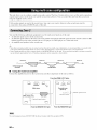
Using REMOTE IN/OUT jacks
When tile components are the Yamaha products and have
the capability of the transmission of the remote control
signals, connect the REMOTE IN jack and REMOTE
OUT jack to the remote control input and output jack with
the monaural analog mini cable as follows.
o,.nol
o., |
| on,rol
in
Infrared signal
receiver or
Yamaha
component
Yamaha
component
(CD or DVD
player, etc.)
(
23 En
[[¶'tlfl[_'l{|qlF
iiiiiiiii!iiN__!_!i!!!_!_i_!_i_!!!!_!_i_!!_i_i_i!_!_iiiiiiiiiiiiiiiiiiiiiiiiiiii
iii;ia!_a_!i!
!i!i!!i!!i!!i!!i!!
!!i!!i!
i!!i!!i!
!i!!i!!i!!i!!i!!
i!!i!!i!
!i!!i!!i!!i!!i!!
i!!i!!i!
!i!!i!!i!!i!!i!!
i!!i!!i!
!i!!i!!i!!i!!i!!
i!!i!!i!
!i!!i!!i!!i!!i!!
i!!i!!i!
!i!!i!!i!!i!!i!!
i!!i!!i!
!i!!i!!i!!i!!i!!
i!!i!!i!
!i!!i!!i!!i!!i!!
i!!i!!i!
!i!!i!!i!!i!!i!!
i!!i!!i!
!i!!i!!i!!i!!i!!
i!!i!!i!
!i!!i!!i!!i!!i!!
i!!i!!i!
!i!!i!!i!!i!!i!!
i!!i!!i!
!i!!i!!i!!i!!i!!
i!!i!!i!
!i!!i!!i!!i!!i!!
i!!i!!i!
!i!!i!!i!!i!!i!!
i!!i!!i!
!i!!i!!i!!i!!i!!
i!!i!!i!
!i!!i!!i!!i!!i!!
i!!i!!i!
!i!!i!!i!!i!!i!!
i!!i!!i!
!i!!i!!i!!i!!i!!
i!!i!!i!
!i!!i!!i!!i!!i!!
i!!i!!i!
ii!i
i¸
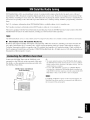
(U.S.A. model)
Both FM and AM indoor
unit. Connect
each antenna
terminals.
In general,
sufficient
signal strength.
antennas
are supplied
correctly
with this
to the designated
these antennas
should
provide
To the AC wall outlet
See page 8 htr connection inflwmation of the supplied indoor FM
atttmma and AM loop antemta.
• The AM loop antenna should be placed away l?om this unit.
• The AM loop atttenna should always be connected, even if an
outdoor AM antmma is connected to this unit.
• A properly installed outdoor antenna provides clearer reception
than an indoor one. If you experience poor reception quality,
install an outdoor antenna. Consult the nearest authorized
V:ln]aha dealer or service center about outdoor antennas.
Indoor FM
antenna
(supplied)
AM loop
antenna
;(supplied)
•
AC OUTLET(S) (SWITCHED)
U.K. and Australia
models .....................................
l outlet
Korea model ...............................................................
Other
models .........................................................
None
2 outlets
Use these outlet(s) to supply power to any connected
components.
Connect the power cable of your other
components
to these outlet(s). Power to these outlet(s) is
supplied when the main zone or Zone 2 is turned on. However,
po'a.er to these outlet(s) is cut off when the main zone and
Zone 2 are turned off or when @ MASTER ON/OFF on the
Outdoor AM antenna
Use a 5 m 10 m (161o 3:;
t_)vinyl-co_ercd wire
extended
OIl[doors
[/'onl
window.
Ground (GND terminal)
For maximum sat_ty and mininmm interi_:rence, connect the
antenna (-}ND terminal 1o a good earth ground. A good earth
ground is a metal stake drivcn into nloist ealth.
a
front panel is pressed and released
position. For information
outward
on the maximum
to the OFF
power or the total
power consumption of the components that can be connected
to these outlet(s), see "Specifications"
on page 109.
The power to AC OUTLET(S) of this unit is not cut off while this
unit is charging connected iPod even when this unit is in the
standby mode. When this unit completes charging or the iPod is
disconnected, the power is cut off atttomatically when this unit is
in the standby mode.
Memory back-up
The memory back-np circuit prevents the stored data
from being lost even if thisunit is in the standby mode.
Ho'a,ever, the stored data "a,ill be lost in case the pov,,er
cable is disconnected from the AC wall outlet or if the
power supply is cut oft"for more than one week.
24 En
,qfff_f|qf_
Caution
If you are to use 6 ohm speakers, set "SP IMR" to
"6f2 MIN" as follows BEFORE using this unit. 4 ohm
speakers can be also used as the front speakers.
1
Press and hold @TONE
CONTROL
on the
This unit turns on, and tile advanced setup menu
appears in the front panel display.
TO.E
COmROL While holding
%
MASWR
-
down
Rotate the @PROGRAM
selector on the
CONTROL
on the front
panel repeatedly to select "6f_ MIN".
5
Press @MASTER
ON/OFF
Turning off this unit
Press @MASTER
ON/OFF on the front panel
again to release it outward to the OFF position to
turn off this unit.
• @MAIN
ZONE ON/OFF on the front panel as well as
@POWER
,_
"SP IMP." and the current speaker impedance setting
("8f.) MIN') appear in the front panel display.
Press @TONE
•
o
front panel to select "SP IMP.".
4
Press @MASTER
ON/OFF on the front panel
inward to the ON position to turn on this unit.
When yon turns on this unit by pressing @MASTER
ON/OFF, the main zone is turned on.
When you turn oi/this unit. there will be a 4 to 5_second delay
belk_re this unit can reproduce sound.
front panel and then press @MASTER
ON/
OFF inward to the ON position to turn on this
unit.
3
Turning on this unit
Make sure this unit is turned off.
Refer to the right colunm for details.
2
•
and (_)STANDBY
oi/the remote control are
operational only when @MASTER
inward to the ON position.
ON/OFF is pressed
• Basically, we recommend that you use the standby mode to turn
olT this unit.
•
Set the main zone to the standby mode
Press @MAIN ZONE ON/OFF (or @STANDBY)
to set the main zone to the standby mode.
In the standby mode, this unit consumes a small amount of
power in order to receive infrared signals from the remote
control.
on the front
panel to release it outward to the OFF
position to save the new setting and turn off
this unit.
Note
The setting you made is reflected next time yon turn on this
unit.
•
Turning on the main zone from the
standby mode
Press @MAIN ZONE ON/OFF
turn on the main zone.
(or @POWER)
to
• You can also turn on the main zone by pressing _SCENE
@SCENE) buttons.
(or
• When you turn on this unit. there will be a 4 to 5-second delay
before this unit can reproduce sound.
• These buttons are operational only when @ MASTER
OFF is pressed inward to the ON position.
ON/
25 En
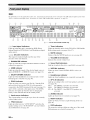
The XM indicator is only applicable to the U.S.A. and Canada models and the cursor oil the left of the XM indicator lights up only when
"XM" is selected as the input source. For details, see "Basic XM Satellite Radio operations" on page 54.
@ ........
@@ Input signal indicators
Lights up when this unit is reproducing DSD (Direct
Stream Digital) or PCM (Pulse Code Modulation) digital
audio signals.
@@@ Decoder indicators
The respective indicator lights up when any of the
decoders of this unit function.
@
ENHANCER
Lights
@
@
DOCK
Lights
IN 1 or HDMI
CINEMA
is selected
indicator
and a sound
is selected
of the stationed
@ Input
source
The corresponding
selected
your iPod in a Yamaha
terminal
iPod
sold separately)
of this unit (see page 23)
as the input source.
The DOCK
iPod in the standby
the
cursor
any modifications
26 En
@ VIRTUAL indicator
Lights up when Virtual CINEMA DSP is active (see
page 46).
@ Headphones indicator
Lights up when headphones are connected (see page 40).
Light up according to
(see page 38).
SP A:
The FRONT
SP B:
The FRONT
SPA B: The FRONT
activated.
the set of front speakers activated
A speakers are activated.
B speakers are activated.
A and FRONT B speakers are
lights up to show the currently
@ NIGHT indicator
Lights up when you select a night listening mode (see
page 49).
indicator
settings
@ Sound field indicators
Light up to indicate the active sound fields (see page 42).
@ ZONE2 indicator
Lights up when Zone 2 is turned on (see page 91 ).
indicators
up when you run "AUTO
speaker
@ MUTE indicator
Flashes while the MUTE function is on (see page 40).
mode.
input source.
YPAO
@ Tuner indicators
Lights up when this unit is in the FM, AM or XM Satellite
Radio tuning mode (see pages 50 to 57).
@ SP A B indicators
also lights up when this unit is charging
battery
Lights
are connected
indicator
to the DOCK
and V-AUX
is
IN 2 jacks (see page 16).
clock (such as the YDS-10,
connected
input source
(see page 46).
up "a,hen you station
universal
@
mode is
indicator
up v,,hen headphones
field program
@
Enhancer
indicator
SILENT
Lights
Music
up when the signal of the selected
input at HDMI
only
@ VOLUME level indicator
Indicates the current volume level.
(see page 46).
HDMI
Lights
models
indicator
up when the Compressed
selected
U.S.A. and Canada
set in "AUTO
SETUP"
SETUP"
(see page 28).
and when the
are used without
@ DSP indicators
The respective indicator lights up when any of the sound
field programs are selected (see page 42).
.qftf[ff1¢|'tf_-
@ Multi-information display
Shows the name of the current sound field program and
other information when adjusting or changing settings.
The remote
control
transmits
@ SLEEP indicator
Be sure to ailn the remote
Lights up while the sleep timer is on (see page 41).
control
sensor
a directional
control
directly
on this unit during
@ 96124 indicator
infrared
ray.
at the remote
operation.
Remote
control
sensor
Lights up when a DTS 9(,/24 signal is input to this unit.
@ Input channel and speaker indicators
I
LFE indicator
Presence speaker indicators
,_,a_,_w,2Z,=
['-L] [C---_[Nllnput
_
_=
0000
ch mnel indic tlors
Stur(
und
back
st eaker
indical(
/
rs
Approximately 6 m (20 ft)
€
LFE indicator
Lights
up when the input signal
contains
the LFE
signal.
Input
Indicate
channel
indicators
tile channel
componeuts
of tile current
digital
input signal.
Presence
Infrared
and surround
Outputs
back speaker
component
indicators
Light up according
surround
window
infrared
to the number
of presence
set for "EXTRA
and
Flashes
(see page 72) and "SUR.B L/R SP" (see page 73) in
"SOUND MENU" when this unit is in the auto setup
signals.
(see page 28) or the speaker
Operation
level setting
in "SOUND
(see page 74) procedure.
_%,._
The fuuction
mode selector
AMP
• To use the presence speakers, set "EXTRA SP ASSIGN" to
"PRESENCE" (see pages 29 or 72).
Operates
Aim this window
at tile
indicator
"a.llile tile remote
• You can make settings for surround back speakers autonlatically
by running "AUTO SETUP" (see page 28) or manually by
at{jnsting settings for "SUR.B L/R SP" (see page 73) in
"SOUND MENU".
signals.
you want to operate.
@TRANSMIT
SP ASSIGN"
MENU"
back speakers
(@)
control
Operates
mode
control
selector
of some buttons
is sending
infrared
(@)
depends
on tile operation
position.
the amplifier
function
of this unit.
SOURCE
selector
tile component
button
selected
with an input
(see page 87).
TV
Operates
the TV assigned
PHONO
(see page 86).
to either
DTV/CBL
or
• Do not spill water or other liquids on the remote control
• Do not drop the remote controh
• Do not leave or store the remote control in the lbllowing types
of conditions:
places of high humidity, such as near a bath
places of high temperatures, such as near a heater or stove
places of extremely low temperatures
dusty places
• To set the remote control codes for other components, see
page 88.
27 En
I
This unit employs
troublesome
the YPAO (Yamaha
listening-based
optinfizer microphone
environnlent.
speaker
collects
Parametric
Room
setup and achieves
and this unit analyzes
Acoustic
highly
the sound
Optimizer)
accurate
your speakers
2
technology
which
sound adjustments
produce
in your actual
The supplied
listening
Connect the supplied optimizer microphone
to the OPTIMIZER
panel.
Notos
lets you avoid
alltomatically.
MIC jack on the front
• Be advised that it is normal lor hind test tones to be output
during the "AUTO SETUP" procedure.
• To achieve the best results, make sure the room is as quiet as
possible while the "AUTO SETUP" procedure is in progress. If
there is too much ambient noise, the results may not be
satisfactory.
"4¢:
• You can run "AUTO SETUP" using the systmn menu thal
appears in the OSD or in the front panel display. This manual
uses the OSD illustrations to explain the "AUTO SETUP"
procedure.
• Belkwe perlonning operations, set the operation mode selector
on the remote control to (_)AMP.
• This unit uses the speakers connected to the FRONT A speaker
terminals as the front speakers lk_rthe a@lstment.
Omni-directional
.....................................
I_
The follovdng
monitor.
menu screen
microphone
appears
on the video
gLl_ O_IqENU
Make
before
sure
of the following
starting
the AUTO
SETUP
operations.
Speakers
[21
[21
Headphones
are disconnected
from this unit.
This unit and the video monitor are turned on.
[21
The connected
subwoofer
appropriately.
is turned
less).
[21
The crossover frequency controls of the
connected
subwoofer is set to the maximum.
[21
The room
quiet.
[_]![>]_Seiect
on and the
level is set to about half way (or slightly
is sufficiently
÷ EXTRA 5F' PSSIGH
ZCllqlE2 ::FROHT B
F'RESEIE:E
HOHE
SETUP, ......
I:ILITO
E¢! .......
140TURJ:IL
STPRT
points
[21
volume
are connected
check
Place the optimizer microphone at your
normal listening position on a flat level
surface with the omni-directional
microphone
heading upward.
Optimizermicrophone
It is recommended that you use a tripod (etc.) to affix the
optimizer microphone at the same height as your ears would
be when you are seated in your listening position. You can
use the attached screw of a tripod (etc.) to fix the optimizer
microphone to the tripod (etc.).
28 En
)l_ltllllt41allldal:l_._l,I:_.l;(;lJ.'_;l_'J[_Yl,
4
Press @<1 / L> to select the desired setting
for "EXTRA SP ASSIGN" and then press @V.
Press @<1/_>
"EQ".
Extra
Parametric
speaker
i::?=...:T_:::u"_ ,::?i::)
assignment
_"K:?,::? T _':::M
Selects the function of tile speakers
EXTRA SP terminals.
Choices:
FRONT
B, ZONE2,
connected
to the
NONE
• When you use the alternative front speaker
system (see page 38)
Select "FRONT B".
• When
you use the Zone
2 speakers
(see
Select "ZONE2"
to set the function
to the Zone 2 speakers.
speakers
of the speakers
This unit drives the Zone 2
by using the internal
you use the presence
speakers
(see
page 12)
Select
speakers
• When
to set the function
to the presence
of the
you do not use the EXTRA
select the type of the parametric
"NONE"
to deactivate
the EXTRA
SP
terminals.
• Select
"NATURAL"
to average
of all speakers
being less emphasized.
setting
adjustment
"FLAT"
to average
are of similar
of each speaker
if the FLAT
the frequency
Recommended
"FRONT"
frequencies
Recommended
a little harsh.
speakers
out the frequency
with higher
sounds
Press
response
if all of your
quality.
to adjust
the frequency
in accordance
response
with the sound of
Recommended
are of much higher
@V to select
(_IENTIER
if your front
quality
than your other
"START"
and then
to start the setup
procedure.
This unit starts the auto setup
11you select "ON" in "BI-AMP" (see page 96), you cannot
selecl "PRESENCE" or "ZONE2" in "EXTRA SP
ASSIGN".
Press @<1 / E> to select "SETUP"
press @_.
equalizer
speakers.
terminals
Select
the
root]] and
from the following choices.
Choices: NATURAL,
FLAT, FRONT
speakers
SP
selects
bands for the listening
your front speakers.
speakers.
the level of the specified
adjusts the level of the selected frequency bands to
create a cohesive sound fiekt in the room. You can
• Select
"PRESENCE"
adjusts
E(;!
bands. This unit automatically
frequency
of all speakers.
• When
type
frequency
• Select
amplifier.
equalizer
equalizer
response
page 91)
to select the desired setting of
Parametric
crucial
PRESENCE,
l#lBi_(_!allalligeI,11i
procedure.
tones are output
from each speaker
setup procedure.
Once
"AUTO:RESULT"
press
Loud test
during
the auto
all items are set, the
display
appears
in the OSD.
and then
Choices: AUTO, RELOAD, UNDO, DEFAULT
• Select "AUTO" to automatically run the entire
"AUTO SETUP" procedure.
• Select "RELOAD" to reload the last "AUTO
• During the auto setup procedure, do not perform any
operation on this unit.
• We recommend that you get out of the room while this unit
is in the auto setup procedure. It takes approximately 3
minutes for this unit to complete the atttu setup procedure.
SETUP" settings and override the previous
settings.
• Select "UNDO" to undo the last "AUTO SETUP"
settings and restore the previous settings.
• Select "DEFAULT" to reset the "AUTO SETUP"
parameters to the initial factory settings.
• "RELOAD" or "UNDO" is axailable only whet] you have
previously run "AUTO SETUP" and confirmed the results.
• "RELOAD" or "UNDO" is not available when you change
the setting of "BI-AMP" in the advanced setup (see
page 96) or "EXTRA SP ASSIGN" in "SOUND MENU"
(see page 72).
29 En
This unit performs
Speaker
the following
wiring
t,ii F;;:]I
MG
Checks
which speakers
polarity
of each speaker.
Speaker
size
The results displayed under "RESULT" are as
l\)llows:
checks:
are connected
and tile
$ iZE
distance
i-,T(::'"r,",M,".i::2
Checks the distance of each speaker from the
listening position and adjusts the timing of each
channel.
Equalizing
Checks
level
the vohnne
level of each speaker.
The display changes as %llows:
gUT0=REHU
E',qTRA
L:PPSSiGM
ZCIIJE2>FROIqT
B
+
F'RESEIfiCE
HOHE
SETLIF'. ......
AUTO
EL_!
.......
IqATtlR#L
ST#RT
r,_.] [ ',r] _UF'[,o_,_n
D4] '[_'] _S,.=] eci.
!
gl_lTO _C:HEC:}:
INITIIqI_IZilqg
+ i,]l
Rllqg
51ZE!DISTgHCE
EQLIRLIZ iIqG
LEUEL
CHEL-:K L-:H=CEHTER
iiiil
........
:!!!;l:::'
of speakers
Speaker
distance
DIS"[
Displays
the speaker
distance
position
in the following
Closest
speaker
Speaker
level
Displays
order:
from tile listening
speaker
RESULT
SF'
_
3,4/0, i
DiST_
14. L],'i7.L]ft
LUL _ -'?,g'+B,5dB
+ ?EET
CAI%-:EL
output
output
level in the following
level/Highest
speaker
output
• If "E-10:INTERNAL ERROR" appears during the testing
procedure, restart from step 4.
• If you selected other than "AUTO" in step 5, no test tones
are
output.
• If an error occurs during the "AUTO:CHECK" procedure.
the setup procedure is canceled and an error screen
appears. For details, see "If an error screen appears" on
page 32.
• When this unit detects potential problems during the
"AUTO SETUP" procedure. "WARNING" and the
number of warning messages appears in the above of
"RESULT" (see page 32).
• Depending on the listening environment. "SWFR
PHASE:REV" appears during the "AUTO:CHECK"
procedure and "SUBWOOFER PHASE" in "SOUND
MENU" (see page 74) is automatically set to
"REVERSE".
Press @/\ and then @ENTER
setup results
to display the
in detail.
RESUI_T
SP
_
3,'4/_?_i
DiST_ 14 J?/17 J_,f L
LUL ; .-'?,n'_6,5dB
)SET
CAHCEI_
[_] ,[T] _UF '[/c,t,_r,
[ EHTER ] ::
Epter
[ ENTER ] _ Er,<:er
RESULr_,_IR
11,4G
FR011TL. ......
OK
1
T
[4]i[_]_Select
[EIq_ER ] _Return
30 En
distance
LJ...iJ
....
gLITO_RESULT
I_UTO:'
RESULT
to this
order:
distance/Farthest
the speaker
speaker
connected
order:
of all the
i i::2iii:::.i
and adjusts
the number
Lowest
level
_:::.,.-,i
_,...,_
'r"::=
T id,::
Checks and adjusts the tonal characteristics
speakers by the setting of"EQ".
Speaker
of speakers
Displays
unit in the following
Front/Back/Subwoofer
Checks the frequency response of each speaker and
sets the appropriate
low-frequency
crossover l\_r each
channel.
Speaker
Number
)1171_llllt'41allldal:lt._l_I:_.ll(;lJ.'_:l_lffffJ[_'l_1#lBi_(;lallallIgeI_11i
Press @<1 / E> repeatedly to toggle between
10
the setup result displays.
Press @IENTIER to return to the top
"AUTO:RESULT"
Press (_)A / V to toggle between the parameters in a
results.
display.
gLIT Cl_RESLILr
RESLILT
SF'
_
3/4/0,
t
DIST:
t4_0, t7_O?t
LL!L _ .-9,0/+6,,5dB
?¸SET
C:glqCEL
==_ Results of the speaker
connection
and wiring
[±] ,, Iv] _LIF,,Do_r,
[ EI'_TER] _=
Enter ¸
Results of the speaker
distance from the
listening position
11
Make sure the pointer is pointing at "SET"
and "CANCEL" and then press (_)<1 / c> to
select "SET" or "CANCEL".
AUT0_ RESULT
Results of the setting of
each speaker size
RESULT
SF'
_
:_,4/0, l
DiST;
14_0,17_0;t
LUL _ -9_0'+6_5dE'
÷ ?SET
C:AI'IC:EL
[&]
['_']_=UF 'Dc,_,:r,
[ El'IT ER] _Enter
Choices: SET, CANCEL
• Select "SET" to confirm the "AUTO SETUP"
results.
• Select "CANCEL" to cancel the "AUTO SETUP"
results.
Results of the parametric
equalizer of each speaker
12
Results of the speaker
output level
Press @IENTIER to confirm your selection.
The top "SET MENU" display appears in the OSD.
SET
If you are not satisfied with the results or want to manually
a_/iust each parameter, use "MANIJAL SETUP" (see
page 69).
÷
MEI'4U
,13LITOSETLIF'
,MAIIUAL SETLIF'
,S IGI'IAL II'IFO
[A] / [',_] _UF ![,o_m
[ EIq]ER ] _Enter
• The distances displayed in the "DISTANCE" results may
be longer than the actual distance depending on the
characteristics of your subwoofcr.
• In the "EQ" results, different values may be set lor the
same frequency to provide finer adjustments.
13
Press @$1ET MIENU to exit from "SET
MENU".
14
Disconnect
the optimizer
microphone
from
this unit.
The optimizer
microphone
away from direct
of this unit.
sunlight
is sensitive
to heat. Keep it
and do not place it on top
"4':
If you change speakers, speaker positions, or the Iwout of
your listening environment, run "AUTO SETUP" again to
recalibrate your system.
31 En
I
•
If an error screen
appears
Press @<1 / C> repeatedly to toggle between
Press @A / V / <1 / _> to select "RETRY" or
"EXIT" and then press @ENTER.
The follov4ng display is an example when "E-9:USER
CANCEL" appears in the OSD.
gUT0_ ERRCIR
÷ E-9_LISER
C:AH[:EL
_rl_l _urlc { iorh,
the warning displays.
WgRI41 IqG: W- 1
<OUT [IF F'HI:4SE>
ee,!el' :=.e Charlrle i
FL
-C:EI,ITER
F'L
PR
SL
SR
SBL
SBR
['a] '[> ] _Select
['ENTER ];Return
?RE',rRV E:,,I T
D"a]'[> ]_Sei ec t
EHTER ]:Enter
• For details about each warning message, see the "AUTO
SETUP" section in "Troubleshooting" on page 102.
• When the corresponding warning message is not
applicable to a speaker, " -' is displayed instead.
Choices: RETRY, EXIT
• Select "RETRY" to retry the "AUTO SETUP"
procedure.
• Select "EXIT" to exit from the "AUTO SETUP"
Press (_IENTIER to return to the top
"AUTO:RESULT"
display.
procedure.
•
If"WARNING"
appears
When this unit detects potential problems during the
"AUTO SETUP" procedure, "WARNING" appears in the
"AUTO:RESULT" display. Check the warning messages
to correct your speaker settings.
Warnings
"AUTO
dilfer
SETUP"
from
errors
in that warnings
do not cancel
Ihe
procedure.
Make sure the pointer is pointing at
"WARNING" and then press @ENTER to
display the detailed information about the
warning.
The number on the right of "WARNING" indicates
the nmnber of warning messages.
gLITOaRESUL, T
WPRI4i HG (3:,
RESULT
SP
:
3'4'_, 1
DiST: 14.g!17,Of{
LUL : -9.6/+6.5d[?
?SET
[:I:IHCEL
[±] !IT] : LIFibc,_,:r,
[ ENTER ] ; Enter
32 En
This unit is equipped with 18 preset SCENE templates for
various situations of using this unit. As the initial factory
setting, the following SCENE templates are assigned to
each SCENE button:
SCENE
SCENE
SCENE
SCENE
2
Rotate the @INPUT selector (or set the
operation mode selector to @AMP and then
press (_<3 / C>) to select the desired
template.
3
Press the @SCENE (or @SCENE) button
again to confirm the selection.
The selected SCENE template is assigned to the
SCENE button.
1: DVD Viewing
2: Disc Listening
3: TV Viewing
4: Radio Listening
If you want to use other SCENE templates, you can select
the desired SCENE templates from the SCENE template
library and assign the templates to the selected SCENE
buttons on the front panel and the remote control.
Select the desired
template
SCENE
or
Front panel
SCENE
template
(Image)
Assign the
SCENE
template to the
SCENE button
library
Remote
control
• If you do not carry out any operation within 30 seconds
l?om the last operation in these steps, this procedure is
automatically canceled.
• Once the desired SCENE templates are assigned to the
corresponding SCENE buttons, you need to set the input
source of the SCENE template on the remote controh See
pa_e 85 lot details.
Press and hold the @SCENE (or ®SCENE)
button for 3 seconds.
The indicator on the selected SCENE button on tile
front panel starts to flash, and the name of the
currently assigned SCENE template appears in the
front panel display.
3 seconds
3 seconds
Q
or
Remotecontrol
Front panel
Flashes
L-'_..-'L. -=
_..-" .i. l:::=i.=..=.i. i" i':::=
33 En
•
Which SCENE template would you like to select?
Which source do you like to
play back?
Video
Which component do you
like for playback?
SCENE
DVD
sources
Default
SCENE buttons
templates
©
DVD Viewing
(DVD video,
Recorded
video)
DVD Movie Viewing
DVD Live Viewing
o{
Music discs (CD,
SACD or DVD-Audio)
DVR
DVR Viewing
DVD
Disc Hifi Listening
Music Disc
Listening
Disc Listening
CD
CD Hifi Listening
CD Listening
CD Music Listening
Radio
programs
TUNER
(FM/AM)
Radio
XM
'
iPod
XM Listening
To ei_joy XM Satellite
connect
Listening
Radio
the XM Mini-Tuner
DOCK
programs,
Dock
you need
(sold
to
separately)
and
i
iPod Listening
To listening
Io the iPod,
iPod universal
dock
you need to connecl
(sold separately)
a Yamaha
to this unit
(see page 58).
_/{
TV programs
]_/_
DTV/CBL
TV Viewing
TV Sports
Viewing
games
_,{
Video
t_/_[
V-AUX
Action
Game
Playing
RPG Playing
Vinyl records
You can creale
34 En
your
original
PHONO
SCENE
templates
by editing
LP Record
the preset
SCENE
lemplates.
Listening
See I _.e
i
i
i
i
( 1 r de alls.
•
Preset SCENE templates
Tile illustrations
of tile SCENE
descriptions
button
in the following
table indicate
tile assigned
SCENE
buttons
in tile default
setting.
SCENE template
Input source
Playback mode
Features
DVD Movie Viewing
DVD*I
MOVIE
Sci-Fi
Select this SCENE template when you play back movies on
your DVD phlyer.
DVD Live Viewing
DVD*I
ENTERTAINMENT
Music Video
Select this SCENE template when you enjoy the music live
video on your DVD player.
DVR Viewing
DVR
MOVIE Drama
Select this SCENE template when you play back movies on
your digital video recorder.
Disc Hifi Listening
DVD*I
PURE DIRECT
Select this SCENE template when you enjoy the high
fidelity sound of the music discs on your DVD player.
Music Disc
DVD*I
STEREO
2ch STEREO
Select this SCENE template when you play back music
discs on your DVD player.
DVD*I
STEREO
Selectthis SCENEtemplatewhenyou play backmusic
Listening
Disc Listening
___
7oh STERE°
CD Hifi Listening
CD*I
PURE DIRECT
Select this SCENE template when you enjoy the high
fidelity sound of the music discs on your CD player.
CD Listening
CD*I
STEREO
2ch STEREO
Select this SCENE template when you play back music
discs on your CD player.
CD Music Listening
CD*I
STEREO
7ch STEREO
Select this SCENE template when you play back music
source on your CD player as the background music.
MUSIC
Select this SCENE template when you enjoy FM 0r AM
Radio Listening
TUNER
I
I
I
ENHANCER
7Ch Enhancer
radio Programs.
i
XM Listening
XM
MUSIC
ENHANCER
7ch Enhancer
Select this SCENE template when you enjoy XM Satellite
Radio programs.
iPod Listening
DOCK (V-AUX)
MUSIC
ENHANCER
7ch Enhancer
Select this SCENE template when you play back music on
your iPod stationed in a Yamaha iPod universal dock.
Viewing
DTV/CBL
ENTERTAINMENT
Sports
Select this SCENE template when you enjoy sports
programs on your TV.
Game
V-AUX .2
ENTERTAINMENT
Action Game
Select this SCENE template when you play action games
such as car racing and FPS games.
ENTERTAINMENT
Select this SCENE template when you play role-playing
Roleplaying
games.
TV Sports
Action
Playing
RPG Playing
LP Record
Listening
V-AUX .2
PHONO
Game
PURE DIRECT
When the connected DVD pla_er or ('D player has the
capability of the SCENE control signals and is connected to
the REMOTE OUT jack of this unit. this unit operates the
DVD player or CD player worked with the SCENE features.
Select this SCENE template when you play back vinyl
records on your turntable.
'2 You can select "V-AUX" as the input source even if your iPod
is stationed in the Yamaha Universal Duck connected to this
unit.
35 En
I
Press @A / V to select the desired parameter
of the SCENE template and then @<1 / c> to
select the desired value of the selected
You can create
SCENE
button.
templates
your original
SCENE
templates
You can refer to the preset
to create
the original
Select the desired SCENE
template
SCENE
for each
parameter.
18 SCENE
You can adjust the following parameters for a SCENE
template:
templates.
Create an original SCENE
template
• INPUT:
The input source component.
• MODE:
The active sound field programs,
STRAIGHT
or Pure Direct mode.
• NIGHT:
The night listening
SCENE template library
(Image)
4
Assign the SCENE
template to the
SCENE button
1
Keeps
mode.
CINEMA:
Sets the night listening
CINEMA mode.
mode to the
MUSIC:
Sets the night listening
MUSIC mode.
mode to the
Press the @SCENE
the edit.
the current
night listening
button again to confirm
An asterisk mark (*) appears by the name of the original SCENE
template,
Turn on the video monitor connected to this
unit.
2
mode (see page 49).
SYSTEM:
• Once the desired SCENE templates are assigned to the
Set the operation mode selector to @AMP
and then press and hold the desired
@SCENE button for 3 seconds.
The SCENE template customizing screen appears on
the video monitor.
corresponding @SCENE buttons, you need to set the input
source of the SCENE template on the rmnote controh See
page 85 lk_rdetails.
• You can create a customized SCENE template lor each SCENE
button, and if you create another customized SCENE template.
this unit overwrites the old customized SCENE tmnplate with
the new one.
• The newly created template is only :r_*ailable lk_rthe assigned
SCENE button.
÷._
DIll)
i ]i @t,/j4"l' _
iI4PIJT:
DUD
blCIDE;:
STRglIGHT
I_
•
Renamethe
t4_-_H,.
T I- T
- z,,
=,,
-T- LI]
: El ITER ] ;IRen_he
Select
[ RETURIq
of "Creating
] _ I-TI:ITI_!I-
then
the name
press
•
Press @A / V to select
•
Press @<1
tile desired
/ Ii:> to place an ....
•
Press @RETURN
•
Press @ENTER
36 En
template
SCENE
at step 3
templates"
and
@ENTER.
repeatedly to recall the desired SCENE template on the
screen.
of the SCENE
your original
When the SCENE template you want to customize is not
assigned to ally of the @SCENE buttons, press @<1 / _>
nlenLi
SCENE templates
space or the desired
character.
(underscore)
character.
to cancel
to confirm
the new name.
the new name.
under
the
Caution
Extreme
Start playback on the selected source
caution
should
back CDs encoded
encoded
be exercised
in DTS.
when you play
If you play back a CD
in DTS on a DTS-incompatible
CD player,
you will only hear some unwanted noise that may
damage your speakers. Check whether your CD player
supports
CDs encoded
in DTS.
output level of your CD player
CD encoded in DTS.
Also, check the sound
before
you play back a
_%,._
To play [)TS-encoded CDs when using a digital audio
commctiou, set "DECODER MODE" in "INPUT MENU" to
component or select a broadcast station.
• Refer to the operating instructions for tile source
component.
• See page 50 for details about tuning instructions.
• See page 54 for details about XM Satellite Radio
tuning instructions.
Rotate @VOLUME (or press @VOLUME
+/-)
to adjust the volume to the desired output
level.
"DTS" before the playback (see page 80).
• See page 48 to acliust the level of each speaker.
• This does not affect the AUDIO OUT (REC) level.
• You can set the initial volume level and maximum volume
Befl)re performing the %llowing operations, set the operation
mode selector on the remote control to @AMP.
level (see page 77).
Turn on the video monitor connected to this
unit.
See page 40 to display the input source inhwmation on the
video monitor.
2
Rotate the @ PROGRAM selector (or press
one of the sound field program selector
buttons ((_)) repeatedly) to select the desired
sound field program.
The name of tile selected sound field program appears
in the front panel display. See page 42 for details
about sound field programs.
Rotate the @INPUT selector (or press one
of the input selector buttons (@)) to select
the desired input source.
,:;7.-..;
....==.. &
Dw
v-Aux
&
input sources
%
i vcR
_
Currently selected sound field program
The name of the currently selected input source
appears in the front panel display for a few seconds.
Available
-..iZ" .;
DW/CBL_DVD
.i. i"..=i"- LJ i ==
_D,_D R
TU_E_ CD
L."=='.'=L.'=
I
XM
PH_0_
I
/
Sound field programs canuot be selected when the
component connected to the MULTI CH INPUT jacks is
selected as the input source (see page 38).
_%,._
Currently
source
selected
input
The corresponding input selector button on the remote
control lkwthe currently selected input source lights up for
approximately 5 seconds after you press any buttons on the
remote control, showing which source component is
currently being operated.
• Choose a sound field program based on your listening
preference, not merely on the name of the program.
• When you select an input source, this unit automatically
selects the last sound field program used with the
corresponding input source.
• To display information about the currently selected sound
field program in the OSD, see page 61 lor details.
37 En
l$/,_,'g=t
•
A quick guide to contents
See
When you want to...
page
Enjoy pure hi-fi stereosound
48
A_!justtile tonal quality of the front speakers
48
A(!just the parameters of sound field programs
61
Enjoy sources with a wide dynamic range at night
49
Use headphones
40
Enjoy multi-channel sources in 2-channel stereo
49
Select a decoder to play back sources with
66
Automatically set this unit to the standby mode
41
Use this feature to turn the front speaker
A and/or
FRONT
Press @SPEAKERS
Use this feature
MULTI
to select the component
CH INPUT jacks
connected
the @INPUT
(or ®MULTI
I
to the
(see page 22) as the input
"MULTI
selector
to select
MULTI
CH IN).
CH" appears
in the front panel disphty.
(FRONT
on the front panel
repeatedly to turn on or off the set of front
speakers connected to the FRONT A and/or
EXTRA SP speaker terminals.
The active front speaker set changes as follo'a,s.
source.
Rotate
system
B) on or oft'.
CH
FRONT
OFF
A____
(---
FRONT A
FRONT B l
and
FRONT B
• FRONT A and B or FRONT B setting is not available when
"EXTRA SP ASSIGN" is set to "PRESENCE". "ZONE 2" or
"NONE" (see page 72).
• Turn olT the vohmm level of this unit when you switch the lhont
speaker setting.
•
Using the Zone B feature
When you set "FRONT B" to "ZONE B" (see page 72),
you can use the speakers connected to the EXTRA SP
speaker terminals in another room (Zone B).
_%,._
Use "MULTI CH SET" mmm in "INPUT MENU" to set the
Press @SPEAKERS
parameters Ii_r MULTI CH INPUT (see page 80).
repeatedly to turn on or off the Zone B speakers.
When you activate the Zone B speakers, all the speakers in
the main room are muted.
Note
on the front panel
Sound field programs and the night listening mode cannot be
selected when the component connected to the MULTI CH
INPUT .jacks is selected as the input source.
• You cannot actNate both the main room and Zone B speakers
simultaneously.
• If you select CINEMA DSP sound lield program and activate
the Zone B speakers. Virtual CINEMA DSP activates
automatically (see page 46).
38 En
_O'v,',m-._;
This unit comes
feature
jacks
(audio
with a variety
input jack select)
of input jacks.
to switch
Use this
between
when more than one input jack is assigned
input
You can display the operating information of this unit on a
video monitor.
to the
same input source.
1
Turn on the video monitor connected to this
unit.
• We recommend that you set the audio input jack select to
"AUTO" in most cases.
• You can adjust the del:mlt audio input jack select of this unit by
using "AUDIO SELECT" in "OPTION MENU" (see page 83).
Press @AUDIO
SELECT
(or @AUDIO
SEL)
repeatedly to select the desired audio input jack
select setting.
Available
2
Set the operation mode selector to @AMP
and then press (_DISPLAY
control.
The current status screen appears in the OSD.
5TI?TLIS
UOL _-4€_,, €_dB
M[ll,JI E
5ci-gi
i HPLIT:
IZl,,SEL _
input sources
HIGHT;
I vcR
Dw
wAux
DWiCSL_OW
i I:::l.. ':::;]:::] ::
MDICD-R TU_ER ¢D
XM
on the remote
DUD
HI)I,1i
OFF
PHON
I:::I]rT'_"l_
You can select the amount of time that the current status is
Currently selected audio input jack select setting
174U"['0
i=.ir'.,i.,.i
I,L"r
i IL,='I
Automalically selects input signals in the
lk)llowing order: (1) HDMI (2) Digital
signals (3) Analog signals.
displayed in the OSD by using the "OSD-AMP"
in "OPTION MENU" (see page 82).
The OSD signal is nol output
will nol be recorded.
al the VIDEO
parameter
output jacks
and
Selects only• HDMI signals. When HDMI
signals are nol inpul, no sound is output.
,....,...,r"_,",.'mm_"_""
...mOT,...,_
_
Automalicallv selects input signals in the
lk)llowing order: (1) Digital signals input
at the COAXIAL jack. (2) Digital signals
inpul at the OPTICAL jack. When no
signals are input, no sound is outpul.
r'H..i_"_i
mm
Selects
only
analo_
Si_llals.
If
no
aoalo_
signals are input, no sound is outpul.
This li:ature is not available when no digital input jacks
(OPTICAL. COAXIAL and HDMI) are assigned. In addition.
HDMI is i_ot available as an audio input jnck select setting when
the HDMI IN l and HDMI IN 2 jacks are not used. Use "I/O
ASSIGNMENT" in "INPUT MENU" to reassign the respective
input jack (see page 78).
39 En
Connect a pair of headphones with a stereo
analog audio cable plug to the PHONES jack on
the front panel.
You can combine a video image from a video source with
sound from an audio source. For example, you can enjoy
listening to classical music while viewing beautifld
scenery from the video source on the video monitor.
Press the input selector buttons (@) on the
remote control to select a video source and then
an audio source.
When you select a sound field program. SILENT CINEMA mode
activales automatically (see page 46).
Audio
sources--
Video
sources--
Set the "BGV" parameter in the "MULTI CH SET" menu to the
desired setting to select the del:mlt background video input source
of the MULTI CH INPUT sources (see page 80).
Noto :
• When you connect headphones, no signals are output at the
speaker terminals.
• All Dolby Digital and DTS audio signals are mixed down to the
left and right headphone chatmels.
You can display
the format,
sampling
bit rate and flag data of the current
frequency,
channel,
input signal.
Set the operation mode selector to @AMP
and then press @SET MENU on the remote
control.
Press @MUTE
audio
on the remote
control
to mute the
The top "SET MENU" disphty appears in the OSD.
output.
Press @MUTE
again to resume
the audio output.
SET
HEHLI
--T-• You can also rotate @VOLUME
+
on the front panel or press
@VOLUME +/- to resume the audio output.
• You can adjust the muting level by using the "MUTE TYPE"
parameter in "SOUND MENU" (see page 76).
• The MUTE indicator flashes in the front panel displ W when the
audio output is muted and disappears Dora the front panel
display when the audio output is resumed.
,IqLITCI SETUP
,MI:IMLIIOL
SETLIP
,SiS_I_L IHFO
[ EI4_ER ] ; Enter
Press @V repeatedly to select "SIGNAL
INFO" and then press @ENTER.
The audio information about the input source appears
in the OSD.
3
Press (_)<_/_> to toggle between the audio
and video information displays.
4
Press @SET
MENU
on the remote control
again to exit from "SET MENU".
40 En
•
Audio information
Set the operation mode selector to @AMP
i=<¢=li:::'h'i¢"I"i_
Si_[l;[]
format.
digila]
signal,
analog
input.
Tile
....,::,"Mviii:)i,r..ll,
_...._.
H,..._'r
;.i_':::
\¥hcn
number
tlJS
Ul]il
il aulonmtically
of
samples
per
dLqcct
Lal]l]Ot
swilchcs
second
a
Io
taken
l¥om
a conlinuous signal Io make a discrete signal.
Tile
,...ql=q"Ji"d"ii"ii::rilr"l
H l "ll...l ....
number
of
sou
channels
rcc
Tile number of bits
passing
and
repeatedly to set the
Each time you press @SLEEP, the front panel display
changes as shown below.
in tile inpul
signal (fionUsurround/LFE). For example, a
mulli-channel soundtrack wilh 3 front
clmnnels, 2 surround channels and LFE, is
displayed as "3/2/0.1 L
_...,i::'
a.T
<'i"
i:::'_
i:::,
v..
r,"¢r
'<,_ _....
then press @SLEEP
amount of time.
a given
poilll
per
second.
The SLEEP
amount
set, the SLEEP
display,
i:::i_...r......_r.'::: Flag dala encoded in DTS, Dolby Digital, or
PCM signals thai cue Ihis unil to automalically
switch decoders.
indicator
flashes
while you are switching
the
of time for the sleep timer. Once the sleep timer
indicator
and the display
is
lights up in the front panel
returns to the selected
sound
field
program.
Flashes
....
appears when this unit cannot display the corresponding
information.
•
¢" i
,%1
.... , i,,,,
r"
I,,,
i,,,,
r"
I,,,
i,,,,
i":
I,,,
i
,i ,":
I
,i,
,,
,i,,,
i":i ....
h,l
,,,,,
III
i i
: ,.
I
,i,
I'I
I I
#
Video information
Lights up
"
li"JI I...<I
i"_i','i I "l'.l....i_::'
Z.l.i...l
i_:: i..
I _h"i
I"I I.....
i
'
li"J
_i...<_
i"d','i
la.T i=,
_'.. i=',2::=:
_........,
Type of tilL' source
video
signals
and
lilt..
video signals output al the HDMI OUT
jack of Ihis unit.
Resolution
of the inpul
sigl]al
(analog
iq[:'M
i i!!!?:;?.i:;;:0i:;?.
Error
message
for HDMI
....
: if'::_i-i i i"i i"i i
or
HDMI) and Ihe oulput signal (HDMI).
When inpul video siglmls are composite
vkleo or S-video signals, the inpul video
sigl]als are indicaled as "Comlx)sile" or
"S-Video'.
sourcesor
connecled HDMI devices. See page 102
for demils.
•
Canceling
the sleep
Press @SLEEP
until "SLEEP
display.
timer
on the remote control repeatedly
OFF" appears in the front panel
Disappears
....
appears when this unit calmot display the corresponding
information.
i::::L..i:::.i:::.i.... L.ii" i"
The SLEEP
disappears
seconds.
Use this feature
standby
to automatically
mode after a certain
or recording
automatically
connected
a source.
of time. The sleep
The sleep timer also
turns off any external
to the AC OUTLET(S)
turns off, and "SLEEP
OFF"
after a few
set the main zone to the
amount
timer is useful when you are going to sleep while this unit
is playing
indicator
from the front panel display
components
The sleep timer setting can also be canceled by pressing
@STANDBY (or @MAIN ZONE ON/OFF) to set the main
zone to the standby mode.
(see page 24).
!1
Even if this unit is it] the standby mode. this unit does not cul ofl
the power Io AC OUTLET(S)
while charging connected iPod
(see page 24).
41 En
This unit is equipped
with a variety
almost
any stereo or nmlti-channel
(DSP)
chip containing
several
of precise
sound
sound
digital
decoders
that allow you to enioy multi-channel
source. This unit is also equipped
fiekt programs
with a Yamaha
which you can use to enhance
digital
your playback
playback
sound
from
field processing
experience.
_%,._
• The Yamaha HiFi DSP sound field programs recreate real-world acoustic environments made frunl precise nmasurmnents taken in
actual concert halls, music venues, movie theaters, etc. Thus. you may notice variations in the strength of the reflections coming l?'om
the front, back. lefi and right.
• You can chmlge sound field parameters. See page 61 li)r details.
Rotate the @ PROGRAM
selector (or set the
operation mode selector to @AMP
and then
press one of the sound field selector buttons ((_)
repeatedly).
The name of the selected sound field program appears in
the front panel display and in the OSD.
Note ;
• Sound field programs cannot be selected when the component
connected to the MULTI CH INPUT.jacks is selected as the
input source (see page 38).
• When you play back DTS 96124 sources with any sound field
program, this unit applies the selected program without
activating the DTS 96124 decoder.
• Sampling frequencies higher than 48 kHz are sampled down to
48 kHz or lower and then sound field programs are applied.
• When the sampling frequency of the input sources are higher
than 96 kHz. this unit does not apply any sound field prugrams.
• When yuu selecl an input suurce, this unit automatically selecls
the last suund field prugram used willa lhe currespoudiug input
suurce.
Select a sound field progrmn based un your listening preference, m)t merely on the name ul the program, etc.
Remote control
button
Category of the
program
@
This program
Name of the
program
CINEMA DSP
or
HiFi DSP
Created sound
fields
H,:,<E
clearly reprodltces
You call enioy
a valie{y
backglotllld
music
tl_e finely elabom{ed sound design of {lie latesl science fiction and special ellccts
of cinema{oglaphically
DSP LEVEL
P.INIT.DLY
clealed
P.ROOMSiZE
S.INIT. DLY
villual
space_
leproduced
S. ROOM SiZE
SB INL DLY
with clear
sep !laliOll
belx_een
k'a{llring
dialog,
movies
1
_;()llll{_ efl_2c[ _;alld
SB ROOM SIZE
DIALG. LIFT
-i
Available
Sound
field
sound
field parameters
(see page 63)
indicators
Presence sound field
r
j
SurrouM left
sound field
Listening position
_1_
Surround back sound field
42 En
Surround rivM
sound field
Program description
•
For audio music sources
_.>;,._
FOF
audio
music
SOllrCes,
_r_
also
reLx)mmend
that
you
use
the Pure
Direct
mode
(see page 48).
• The available sound field parameters dilTer depending oil the settings of the speakers.
• "DIALG.LIFT" is available only when "EXTRA SP ASSIGN" in "SPEAKER SET" is set to "PRESENCE"
CLASSICAL
Q_)
1
_"'i ,"_':::":::'
T ,"'_",i
...........
....,
...................
...,,
1...........1 "
H.::_ I {
'I _", r"li .ii"_ 'i _".I"_
[]
(see page 72).
1
HiFi
DSP
This sound fieM simulates a concert hall with approximately 2500 seats in Munich, using stylish wood li)rthe interior finishing as normal
standards for European concert halls. Fine, beautififl reverberations spread richly, creating a cahning atmosphere. The listener's virtual seat is
at the center left of the arena.
DSP LEVEL
INIT. DLY
CLASSICAL
Q_)
ROOM SIZE
LIVENESS
DIALG.LIFT
I .......................
1..........I _
{ ,1
i 1_,,, {,,,
_ I
=1 ii
I,,_,::,_ ]
{
'l i,,,i
!,J
"l i::,_j,-{i,"l,::,_
[]
..........
....,
..................
...,
.....
1
HiFi
DSP
This is an approximately 1700-seated, middle-sized concl:rt hall with a shoebox shape that is traditional in Vienna. Pillars and ornate carvings
create extremely complex reflections from all around the audience, producing a very full, rich sound.
DSP LEVEL
ROOM SIZE
INIT. DLY
LIVENESS
Q_)
[
DIALG.LIFT
I ..... 1 "
...........
".,...................
",....................
[
HiFi
E)SP
This program creates a relatively wide space with a high ceiling like an audience hall in a palace. It offi:rs pleasant reverberations that are
suitable for courtly music and chamber music.
DSP LEVEL
INIT. DLY
LIVENESS
REV.TIME
REV.DELAY
REV. LEVEL
DIALG.LIFT
.........
[ i.ii lr,,c.i_::I
(_)
........
...*,
...........................................
..
[]
[
HiFi DSP
This program simuh,tes a live house with a low ceiling and horn%_atmosphere. A realistic, live soEindfield fcatUl-L,s
powerfid
listener is in a row ill front of a small stage.
DSP LEVEL
INIT. DLY
ROOM SIZE
LIVENESS
LIVE/CLUB
i
T
i {i:::'
,,'l'%J
DIALG.LIFT
i
ii:::'
{,::'l,,,t*:,:,:,,,j
........
....*,
.......................... °ihe
Q_)
sound as d the
.....
[]
i{_e.ii...,i:..i."e
HiFi
DSP
This is the SOulldfkqd of a rock music live house in Los Angeles, with al)ploximate]y 460 seals. Tile listener's vhtua] sL'alis at Ihe cenler ]eft
of the halh
DSP LEVEL
INIT. DLY
LIVE/CLUB
Q_
ROOM SIZE
LIVENESS
[
i
T i {i:::' ..q%i
REV.TIME
REV.DELAY
i ii:::,
REV. LEVEL
DIALG.LIFT
I ........I
"i=_"iI:::,
HrYM'._"H',*_
........
...,................................
{
'; i'_ll:::,
"
[]
[
HiFi
DSP
This is tile sound fieM at stage front in The Bottom Line, a famous New Yorkjazz chlb. The floor can seat 300 people to the lefi and right in a
sound field offering real and vibrant sound.
DSP LEVEL
INIT. DLY
ROOM SIZE
LIVENESS
DIALG.LIFT
43 En
I-xol_nr, it_!l;I,,illl,ll_ Iii/-
•
For various sources
Notes
• The available sound field parameters and the crealed sound fields differ depending on the input sources and the settings of this unit.
• "DIALG.LIFT" is available only when "EXTRA SP ASSIGN" in "SPEAKER SET" is set to "PRESENCE" (see page 72).
.........
I
QT)
l!!!:i"4"l"l!!!:
R"IT4:[i"4ME{".i"[
l .... J "
::::,i:::'
o i'"'b:iii.
_._
1
IC_,_EM_
This program allows the listeners to enjoy stereo sport broadcasts and studio variety programs with enriched live feeling. In sports broadcasts,
tile voices of the commentator and sportscaster are positioned clearly at the center while tile atmosphere of tile stadium expands in an
optimum space to offer the listeners with a feeling of presence in the stadium.
DSP LEVEL
P. INIT. DLY
P. ROOM SIZE
S. INIT. DLY
.........
1
Q_
Ei.4TERTI:4]:i.4MEbiT
S. ROOM SIZE
SB INI. DLY
[ ........ j
_..4,....._...,,-.,_
..., ,,.,.:::,,.,.,
....
SB ROOM SIZE
DIALG.LIFT
A
_.@._
1
ic,,,,E,,a,_,_ 3
This sound field has been suitable for action games such as car racing and FPS games. It uses the reflection data that limits the effects range
per channel in order to offer a powerful playing environment with a being-there feeling by enhancing various effects tones while maintaining
a clear sense of directions.
DSP LEVEL
P. INIT. DLY
Q_)
P. ROOM SIZE
S. INIT. DLY
Ei.4iERiI::4]:i.4MEbii
S. ROOM SIZE
SB INI. DLY
R,:::,:i.eF::i.a'::<i.ng (!!iar,_,_
SB ROOM SIZE
DIALG.LIFT
_._
Ic,,,,_A,_
This sound field has been suitable for role-playing and adventuregames. It combilles the sound field ell__,ctsfor movies and Ihe sound field
designs for "Action Game" to represent the depth and 3D feeling of the field during play, while offering movie-like surround effects in the
movie scenes in tile game.
DSP LEVEL
P. INIT. DLY
•
P. ROOM SIZE
S. INIT. DLY
S. ROOM SIZE
SB INI. DLY
SB ROOM SIZE
DIALG.LIFT
For visual sources of music
Notes
• The available sound field parameters and the created sound fields differ depending on the input sources and the settings of this unit.
• "DIALG.LIFT" is available only when "EXTRA SP ASSIGN" in "SPEAKER SET" is set to "PRESENCE" (see page 72).
Q])
r'.,.,',,".,,::.",
.........
Ii!!:i.4iEi:_m::,':i:i.4Mi!:HT
l ,,,,.,.=..,
.......
J 6@)"
1 I_'"_"*._
This sound field offers an image of a concert hall lk_rlive performance of pop, rock and jazz music. The listener can indulge oneself in a hot
live space thanks to the presence sound field that emphasizes the vividness of vocals and solo play and the beat of rhytlml instruments, and to
the surround sound field that reproduces the space of a big live halh
DSP LEVEL
P. INIT. DLY
44 En
P. ROOM SIZE
S. INIT. DLY
S. ROOM SIZE
SB INI. DLY
SB ROOM SIZE
DIALG.LIFT
RrtTFIlt'q_.l.,...,_,,,_
•
For movie sources
-4<-Youc:m select the desired decoder used with li_llowingsound field program (except "Mono Movie"). See page 66 for details.
• The available sound field parameters and the created sound fields differ depending on the input sources and the settings of this unit.
• "DIALG.LIFT" is available only whmt "EXTRA SP ASSIGN" in "SPEAKER SET" is set to "PRESENCE" (see page 72).
..... [
(E)
M,:::,,..,
:):
E
I ..........
..,...:::,,.,,o_.:::,<..,o_
1 _.¢,J [ >,_o_,,=m
This program creates a sound field emphasizing the surrounding fi.,eling without disturbing the original acoustic positioning of multi-channel
audio such as Dolby Digital and DTS. It has been designed with the concept of "an ideal movie theater", in which the audience is surrounded
by beautiful reverberations front the left, right and rear.
DSP LEVEL
S. INIT. DLY
S. ROOM SIZE
S.LIVENESS
......[
(E)
SB INI. DLY
SB ROOM SIZE
1
SB LIVENESS
DIALG.LIFT
1 "
M,:::,,.,J:):i!!: <:::':::"::''"+::"-"_
.....
C@.}
[
>,._M,,._=l
This program represents the spectacular feeling of large-scale movie productions.
It reproduces a broad theater sound field matching the cinemascope and wider-screen movies with an excellent dynamic range from very
small to extremely large sound.
DSP LEVEL
P. INIT. DLY
P. ROOM SIZE
S. INIT. DLY
......[
QT)
S. ROOM SIZE
SB INI. DLY
SB ROOM SIZE
DIALG.LIFT
1
1 C_J
"
............
.....................'::W".'i....-F'i
i.,_,...,i
rr _::'
[
I_.-_,,.:=_
This program clearly reproduces the finely elaborated sound design of the latest science fiction and special efi'ccts4eaturing movies.
You can enjoy a variety of cinematograpbically created virtual spaces ruproduced with clear separation between dialog, sound effects and
background music.
DSP LEVEL
P. INIT. DLY
P. ROOM SIZE
S. INIT. DLY
......[
S. ROOM SIZE
SB INI. DLY
SB ROOM SIZE
DIALG.LIFT
1
1 "
[
Tiffs progrmn is ideal for precisely reproducing the sound design of action and adventuru movies.
The sound field restrains rc'_erherations but puts emphasis on reproducing a powerfifl space expanded widely to Ibe left and right. The
reproduced depth is also restrained relatively to ensure the separation between audio channels and the clarity of the sound.
DSP LEVEL
P. INIT. DLY
P. ROOM SIZE
S. INIT. DLY
..... [
S. ROOM SIZE
SB INI. DLY
SB ROOM SIZE
DIALG.LIFT
1
1
[
Tbis soundfield featuresstable rew.,rberationsIbat match a wide range of movie genresfrom seriousdramasto musicals andcomedies.The
rexerberations are modest but offer an optimum 3D feeling, reproducing effects tones and background nmsic softly but cubically around clear
words and center positioning in a way that does not fatigue the listener even after long hours of viewing.
DSP LEVEL
P. INIT. DLY
MOVIE
P. ROOM SIZE
S. INIT. DLY
i','il"ii
J 'i" i_::'
S. ROOM SIZE
SB INI. DLY
r,]l"li."lr't
l','h"ti.,i
.....
SB ROOM SIZE
DIALG.LIFT
'I ill:,
[]
] CINEIVIA_
A
This program is provided fi)r reproducing monaural video sources such as a classic movie in an atmosphere of a good old movie theater.
The program produces the optimum expansion and reverberation to the original audio to cruate a comfortable space with a certain sound
deptb.
DSP LEVEL
INIT. DLY
ROOM SIZE
LIVENESS
REV.TIME
REV.DELAY
REV. LEVEL
DIALG.LIFT
45 En
I-xol_1+
r, it_!l;I,,illl,ll_ Iii/+
•
Stereo playback
The available parameters diller depending on the input sources and the settings of this unit.
Use INs program Io mix down multi-channel sources to 2 channels. See page 49 for delails.
DIRECT
...... 1
[
,::7
"i"i:::'
i:::,
_::'
,",
'7,='.i"+
':::;"F
_::i:?i::7
71
J
--_
....
-
1
HiFi
DSP
Use this prognun to output sound from all speakers. When you play hack multi-channel sources, this unit downmixes the source to 2
channels, and then outputs the sound from all speakers. This program creates a larger sound field and is ideal for background music at parties,
etc.
CT LEVEL
SL LEVEL
•
SR LEVEL
SB LEVEL
PL LEVEL
PR LEVEL
The Compressed Music Enhancer
Use INs program Io play back compression arlifacls in 2-channel stereo.
Effect level
ENHANCER
Use
Ihis
program
i','ii i'::7'i' +"' i::Ti,,iL,i¢"H,.h"'i::TiD
Io play
back
compression
arlifacls
+i::=,'=i"+i:::'i'+i"+J::,i"H"a:::'i"'
in 7-channel
- -_ -_ -_ -_
stereo.
Effect level
•
Using sound field programs without
surround speakers
(Virtual CINEMA DSP)
Virtual
CINEMA
DSP programs
DSP allows you to enjoy the CINEMA
without
virtual
speakers
When
you set "SUR.
Virtual
CINEMA
surround
to reproduce
L/R SP" to "NONE"
DSP activates
you select a CINEMA
program
speakers.
the natural
It creates
sound field.
(see page 73),
antomatically
DSP or HiFi DSP sound
whenever
field
(see page 42).
Note
•
Enjoying multi-channel
sources and
sound field programs with headphones
(SILENT CINEMA)
SILENT CINEMA allo'a,s you to enjoy multi-channel
nmsic or movie sound, including Dolby Digital and DTS
sources, through ordinary headphones. SILENT CINEMA
activates automatically whenever you connect headphones
to the PHONES jack while listening to CINEMA DSP or
HiFi DSP sound fiekt programs (see page 42). When
activated, the SILENT CINEMA indicator lights up in the
front panel display.
Virtual CINEMA DSP will not activate even when "SUR. L/R
SP" is set to "NONE" (see page 73) in the lk_llowing cases:
when the component connected to the MULTI CH INPUT
jacks is selected as the input source (see page 38).
when headphones are connected to the PHONES jack.
when this unit is in the "7ch Stere()" mode.
46 En
• SILENT CINEMA does not activate when the component
connected to the MULTI CH INPUT jacks is selected as the
input source (see page 38).
• SILENT CINEMA is not eltcctive when the Pure Direct (see
page 48) or "2ch Stereo" mode (see page 49) is selected, or
when this unit is in the "STRAIGHT" mode (see page 47).
I
Belore
performing
mode selector
the lollowing
on the remote
operalion,
conlrol
sel the operation
to @AMP.
When this unit is in the "STRAIGHT" mode, 2-channel
stereo sources are output from only the front left and right
speakers. Multi-channel sources are decoded straight into
the appropriate channels without any additional effect
processing.
Press (_STRAIGHT
"STRAIGHT".
.D
•
(or (_)STRAIGHT)
i r=:.H
J. E.:ir"i
i
Deactivating the"STRAIGHT"
Press (_STRAIGHT
to select
(or (_)STRAIGHT)
mode
so that
"STRAIGHT" disappears from the front panel
display.
The sound effect is turned back on.
47 En
Belore performing the following operations, set the operation
mode selector on Ihe remote control to @AMP.
You can adjust
listening
playing
the outpnt
to a music
sources
level of each speaker
while
source. This is also possible
input at the MULTI
CH INPUT
when
jacks.
Use the Pure Direct mode to enjoy the pure high fidelity
sound of the selected source. When the Pure Direct mode
is activated,
this unit plays
back the selected
source
with
This operation
"AUTO
the least circuitry.
will override
SETUP"
the level a@lstmenls
(see page 28) and "SPEAKER
made
in
LEVEL"
(see
page 74).
Press
@PURE
DIRECT
to turn the Pure
The @PURE
DIRECT
in the Pure Direct
automatically
Direct
(or OPURE
mode
DIRECT)
on or off.
button lights up while this unit is
mode. The front panel display
1
Press @LEVEL
on the remote control
repeatedly to select the speaker you want to
adjust.
dims.
• The following operations are not possible when this unit is in
the Pure Direct mode:
switching the sound field program
displaying the OSD
atljusting the "SET MENU" parameters (except for level
settings)
operating vide() fimctions (vide() conversion, etc.)
• The Pure Direct mode is automatically canceled whenever this
unit is turned oft.
"l€--
li:7i::u"li"i<T'l'..'...q
"I I
Ii
Front lefl speaker
Ji::ri=u"li"iT_'..,...q
".' J r.<i:::'
IFront
righl
,...._...i><' _ _..A'..
' "_""_ ' _"_....
C enter
S
,...,_.,.q
i.ll.., P><
i...,
....
Suhwoo
when :m operation
pea k er
fer
,:7i lid
i
Surround
leit speaker
,:::<iii:3
ii::,
Stlrrotlnd
right
speaker
Surround
back
left
,:7i lid
The front p:mel display turns on momentarily
is performed.
speaker
i:::,
i
,:::iH:::,;::, i:::,
speaker
Surround back right speaker
Di:::,i..i,::rv..H....,
_i
Presence left speaker
iDi='i..i':gD._
"I....' _'..i='
Use this feature
to adjust the balance
the front left and right speaker
channels.
Speaker and headphone a@lstmm/ts are stored indepm/dm/tly.
CONTROL
on the front
panel repeatedly to select the high-frequency
response (TREBLE) or the low-frequency
response (BASS).
selector to adjust
the high-frequency response (TREBLE) or
the low-frequency response (BASS).
• If you increase or decrease the high-frequm]cy or the lowfrequency sound to an extreme level, the tonal quality of the
surround speakers may not match.
• TONE CONTROL is not elTcctive when PURE DIRECT is
selected, or when MULTI CH INPUT is selected as the input
source.
on the remote control, you can
displayed if "SUR.B L/R SP" is set to either "SMLxI" or
"LRGx 1" (see page 73).
• The available speaker chammls difli_r depending on the
setting of the speakers.
@<1 / C> to adjust
the speaker
level.
• Press @C> to increase the value.
• Press 0<1
Control
48 En
speaker
also select the speaker by pressing @A / V.
• Instead of "SUR.B.U' and "SUR.B.R". "SUR.B" is
Press
Rotate the @ PROGRAM
right
-4¢• Once you press @LEVEL
"4¢'-
Press @TONE
Presence
of bass and treble for
range:
to decrease
the value.
10.0 dB to 10.0 dB
output
• You cannot use the night listening modes in the following
cases:
when the Pure Direct mode (see page 48) is selected.
when the component connected to the MULTI CH
INPUT jacks is selected as the input source (see
page 38).
when headphones are connected to the PHONES jack.
• The night listening modes may vary in elTectiveness
depending on the input source and surround sound settings
You can mix down multi-channel sources to 2 channels
and enioy playback in 2-channel stereo.
Press
(_)STEREO
repeatedly
on the remote
to select
"2ch
control
Stereo".
_.,#._
yOU
use.
• You can use a subwoofcr with this program when "LFE/BASS
OUT" is set to "SWFR" or "BOTH" (see page 74).
• You can also select the "2ch Stereo" mode hy rotating the
@ PROGRAM
selector on the h'ont panel.
• See page 66 for details about the parameters of the "2ch Stereo"
mode.
The night listening
modes
listenability
at lower
1
®NIGHT
Press
repeatedly
are designed
volumes
on the remote
to select
to improve
or at night.
control
"NIGHT:CINEMA"
or
"NIGHT:MUSIC".
Choices:
NIGHT:CINEMA,
NIGHT:MUSIC,
OFF
• Select "NIGHT:CINEMA"
when watching films to
reduce the dynamic range of film soundtracks
and
make dialog easier
• Select
sources
to hear at lower volumes.
"NIGHT:MUSIC"
to preserve
• Select "OFF"
when listening
ease-of-listening
to music
for all sounds.
if you do not want to use this feature.
_.,#._
When a night listening mode is selected, the NIGHT
indicator lights up in the front panel display.
2
Press @<1 / C> to adjust the effect level while
"NIGHT:CINEMA"
or "NIGHT:MUSIC"
is
displayed in the front panel display.
iiiii.F'.F'
e,:::.L,,L..,...,
i ::Hi ill:,
MID, MAX
Choices:
MIN,
• Select
"MIN"
for minimum
• Select
"MID"
for standard
• Select
"MAX"
compression.
compression.
for maximum
compression.
_.,#._
"NIGHT:CINEMA" and "NIGHT:MUSIC" a@lstments
stored independently.
are
49 En
There are 2 tuning
methods:
there is no interference.
the automatic
automatic
If the signal
and manual
preset
the 5 preset station groups).
stations with each other.
and manual.
Automatic
from the station
tuning
features
Furthermore,
tuning
is effective
you want to select
to store up to 40 stations
you can recall any preset
when station
signals
are strong and
is weak, tune into it manually.
(AI to ES: 8 preset
stations
and exchange
station
You can also use
numbers
the assignment
in each of
of two preset
Note
Oriem the connected FM and AM amennas for lhe best reception.
Automatic
strong
1
tuning
is effective
when station
Rotate the @INPUT
3
are
Press @FM/AM
If the signal
received
from the station
you want to select
is
weak, tune into it manually.
selector on the front
panel to select "TUNER"
2
signals
and there is no interference.
as the input source.
to select the reception band.
Manually tuning into an FM station automatically switches the
tuner to monaural reception to increase the signal qualily.
Rotate the @INPUT
selector on the front
"FM" or "AM" appears in the front panel display.
panel to select "TUNER"
Press @TUNING
Press @FM/AM
AUTO/MAN'L
so that the
AUTO indicator lights up in the front panel
display.
up
to select the reception band.
"FM" or "AM" appears in the t>ont panel display.
Press @TUNING
Lights
as the input source.
AUTO/MAN'L
so that the
AUTO indicator disappears from the front
panel display.
.... / .....
.......
, •
P'i_V'i'i
'.....
1'="
, ,i
,:1=,1===7 =
.
V i"i.=:.
No colon (:)
If a colon (:) appears
in the front panel display,
is not possible. Press @PRESET/TUNING
the colon (:) off.
tuning
No colon (:)
to turn
lfa colon (:) appears
is not possible.
Press
@PRESET/TUNING/CI-I
to begin
automatic
When this unit is tuned
indicator
station
50
lights
the colon (:) off.
the TUNED
Press
into a station,
of the received
in the front panel display.
• Press @C> to tune into a higher
frequency.
• Press @<1
t?equency.
En
tuning
to turn
tuning.
up and the frequency
is shown
<1 / C> once
in the front panel display,
Press @PRESET/TUNING
to tune into a lower
tune
@PRESET/TUNING/CH
into the desired
-#Holddown
station
<1 / C> to
manually.
the button to continue searching.
Nr_?J_l_qf_ffp
You can use the automatic
to 40 FM stations
station
numbers
preset tuning
with strong signals
(AI
in each of the 5 preset
order. You can then recall any preset
selecting
1
the preset
station
Rotate the @INPUT
Press @FM/AM
to store up
to ES: 8 preset
station
station
groups)
in
easily by
number.
selector on the front
panel to select "TUNER"
2
feature
as the input source.
• Any slored station data existing under a preset station number is
cleared when you store a new station/lnder the same preset
station nulnher.
• 11Ihe ntunber of received stations does not reach 4(1(E8).
aulomatic preset tuning automatically slops after searching lk/r
all the available slations.
• Only FM slations with sulficienl signal slrenglh are slored
automatically by automatic preset tuning. If the station you
want
to store
is weak ill signal strength,
tune inlo it manually
and store it as described in "Manual preset tuning" below.
to select "FM" as the
reception band.
"FM" appears in the front panel disphty.
You can also store up to 40 stations
station
3
Press and hold @MEMORY
seconds.
for more than 3
2
See page 50 for tuning
instructions.
Press
on the front
@MEMORY
display
indicator
"'-,,
_u_0........
flashes
t_r approximately
.....
"
station
preset
groups)
Tune into a station.
The MEMORY
Flashes
(AI to E8:8
in each of the 5 preset
manually.
1
The preset station number as well as the MEMORY
and AUTO indicators flashes. After approximately 5
seconds, automatic presetting starts from the current
frequency and proceeds toward higher frequencies.
numbers
panel.
in the t_ont panel
10 seconds.
i
,/'"
MEMORY .....
M_M_RY
Flashes
Flashes
When automatic
panel display
station.
preset tuning
is completed,
shows the frequency
the front
of the last preset
"4:-• You can specil} the preset number from which this unit stores
FM stations. Press @AIBICIDIE and then @PRESET/
Press @AIBIClDIE
repeatedly to select a
preset station group (A to E) while the
MEMORY indicator is flashing.
The selected preset station group letter appears.
Check that the colon (:) appears in the front panel
display.
Flashes
TUNING/CH <1 / ;:> repeatedly after you perlk)rm step 3 to
select the preset station number under which the first station
will be stored.
• You car/begin tuning toward lower frequencies to store FM
stations automatically. Press @PRESET/TUNING
so that the
colon (:) disappears lhom the lhont panel display and then press
@ PRESET/TUNING/CH
<1 after pressing and holding
@MEMORY lor more than 3 seconds.
,":
u,.=
__
Preset station
group
=, .Z"..*i
"
"
_ i
<2,,Z:
,:?.
:,,.=:,,.= == ,,-"
i',*iL.i-.:_ H
L=L.
=
Colon (:)
51 En
I._M/:IJ_EflT_ut
Press @PRESET/TUNING/CH
<1/C> to
select a preset station number (1 to 8) while
the MEMORY indicator is flashing.
• Press@C> to select a higher preset station nnmber.
• Press @<1 to select a lower preset station number.
Flashes
Press @PRESET/TUNING/CH
<1/C> on the
front panel (or @PRESET/CH
A / V on the
remote control) to select the desired preset
station number (1 to 8).
The preset station group and number appear in the
front panel display along with the station band and
frequency.
i"i
r"_ ==r" i"
& == _
_ i
:,..=:,..= := ,.-"
_ H
L:L.
Preset station number
Press
@MEMORY
indicator
while the MEMORY
The station band and frequency
panel display
nnmber
You can exchange the assignments
of two preset stations
with each other. The example below describes the
is flashing.
you have selected.
disappears
appear in the front
procedure
to exchange
preset
station
"El"
with "A5".
with the preset station group and
The MEMORY
indicator
from the front panel display.
Select preset station "El" using @A/B/C/DIE
and @PRESET/TUNING/CH
<1/C> on the
front panel.
See "Selecting preset stations" on the left cohmm.
"-
•
....
. ,]
......
]"i .i.l== "" ]"
1"
. ,]
.
,7==1=== :::= ]" ]7,=:.
The displayed station has been stored as AI.
Press and hold @EDIT for more than 3
seconds.
"El" and tile MEMORY indicator fhtsh in tile front
panel display.
Flashes
• Any stored station data existing under a preset station
number is cleared when you store a new station under the
same preset station number.
• The reception mode (stereo or monaural) is stored along
with the station frequency.
iZ" "i
ETi'=*i ,Z,:Z,
_==
_
_ i
,7.
:...=:...= := ..-"
i'dL.b,.=_ H
L'2..
Flashes
You can tune into any desired
the preset
stored.
station
group
station
and number
simply
by selecting
under which it was
Select preset station "AS" using @A/B/C/DIE
and @PRESET/TUNING/CH
<3 / C>.
"A5" and tile MEMORY indicator flash in the front
panel display.
See "Selecting preset stations" on the left cohmm.
When performing this operation with the remote controh set the
operation mode selector to @SOURCE
to select "TUNER" as the input source.
and then press TUNER
Flashes
Press@A/B/C/DIE (or press@A-E/CAT. < / c>)
to select the desired
preset station
group (A to
E).
The preset
station
panel display
button.
52 En
group letter appears
and changes
in tile t_ont
___!=
i
i i
:...=:...= := .."
i H
i ,=L.
Flashes
each time you press the
Press @EDIT again.
"EDIT El-A5" appears in the front panel disphty and
the assignments of the two preset stations are
exchanged.
XM Satellite
Radio
entertainment.
offers an extraordinary
XM is broadcast
in superior
hop, XM has something
for every music
passion
more.
events,
for live sporting
For U.S. custonlers,
For Canadian
infonnation
customers,
This unit is equipped
Satellite
Radio
of commercial-free
digital
audio
fan. XM's
about
dedication
with the Neural
XM Satellite
Surround
Radio
plus the best in sports,
the richest
is available
selection
comedy,
online
news, talk and
from classical
of music
chiktren's
to hip
is matched
programming,
by its
and much
at wwv<xmradio.conl.
is online at "a.'ww.xlnmdio.ca.
decoder
resulting
to playing
news, stand-up
about XM Canada
in multi-channels
nmsic,
from coast to coast. From rock to reggae,
talk radio, up-to-the-minute
information
broadcasts
variety
that plays back the XM HD surround
in a fidl surround
sound content
of the XM
sound experience.
The XM Salellite Radio service is only available in the 48 conliguous United States (not available in Alaska and Hawaii) and Canada.
•
Information from XM Satellite Radio Inc.
Hardware
and required
monthly
may apply. Subscription
Customer
Agreement
the 48 contiguous
the property
Connect
separately)
subscription
fee is consumer
available
United
at xmradio.com
States and Canada.
of their respective
the XM Mini-Tuner
sold separately.
(US resktents)
(32006
subject
and xmradio.ca
XM Satellite
to change.
(Canadian
a one-time
activation
Subscriptions
residents).
Radio Inc. All rights reserved.
Only
fee
subject
to
available
All other trademarks
in
are
owners.
and the XM Dock (sold
to the XM jack on the rear panel of this unit.
For details, see the operating
the XM Mini-Tuner Dock.
Other fees and taxes, including
only. All fees and programming
instructions
provided
XM Mini-Tuner and XM Dock
(sold separately)
with
• To ensure optimal reception of the XM Satellite Radio signals,
the XM Mini-Tuner Dock must be placed at or near a southerly
lacing window with no obstacles in the path to the sky. You can
mount it indoors or outdoors.
• Use the "XM ANTENNA" parameter in "OPTION MENU"
(see page 84) to display the XM Satellite Radio reception level
in the OSD. For the best reception, orient the commcted the XM
Mini-Tmmr so that a value of 60% or more is displayed.
If "CHECK
ANTENNA"
XM Mini-Tuner
the rear panel
Dock
appears
in the front panel
may not be connecled
display,
Io the XM jack
the
on
ol this unit properly.
1_
53 En
IF[4i_.*_i_iF_IMF_f_{_'fTtr,jtsum[o
Once you have installed
inserted
your XM Ready®
antenna,
the XM Mini-Tuner
the XM Mini-Tuner,
connected
home audio system,
yon are ready to subscribe
XM programming.
eight character
There are three
XM Radio
the XM Mini-Tuner
Record the Radio
reference.
Dock,
the XM Dock to
and installed
the
places to find your
ID: on the XM Mini-Tnner,
package,
and on XM Channel
ID in the following
Belure perfornfiug Ibe fulluwiug uperalious, sel Ibe operaliou
mode seleclur un the remute cuntrol Io @SOURCE.
and begin receiving
eight
squares
on
0.
for
1-11511-11-11-11-1[][]
1
Rotate the @INPUT
selector
(or press
@XM) to select "XM" as the input source.
The cursor on the left of the XM indicator lights up in
the front panel display and the XM Satellite Radio
inl\_rmation (such as channel number, channel name,
category, artist name, or song title) for the currently
selected channel appears in the front panel display.
Lights up
The XM Radiu ID dues not use the letters 'T'. "O". "S" or "F".
Activate your XM Satellite Radiu service in the U.S. uuline at
http:l/www.xmradio.com/ur
call 1-800-XM-RADIO (1-800-9672346). You will need a m:@r credit card. XM will send a signal
from the satellites tu activate the l?dl chamml lineup. Activation
normally takes 10 to 15 minutes, but during peak busy periods
you may need to keep yuur XM Ready hume audio system on for
up to an hour. When you can access the full channel lineup on
your XM Ready home audio system you are done. For more
iulormation or to subscribe in Canada. visit XM on the Web at
,:: 77;i;7
When you select "XM" as the input source, this unit
automatically recalls the previuusly selected chauueh
http://www.xmradio.ca/or
call XM's Listener Care at 1-877GET-XMSR (1-877-438-9677).
The XM Satellite Radio signals cannot be output at the
AUDIO OUT (REC) .jacks.
Search for a channel
by using
Satellite Radio search modes.
• To select
a channel
"All Channel
• To select
• To select
"Preset
from the all channel
Search mode"
a channel
Search mode"
one of the XM
list, see
on page 55.
by category,
see "Category
on page 55.
a channel
from the preset
Search mode"
channels,
see
on page 55.
• To select the desired channel directly by entering
the channel number, see "Direct number access
mode"
on page 55.
_.,#._
• You can use the Neural Surruuud decoder to ei_ioy the XM
HD surround sound content of the XM Satellite Radio
broadcasts in multbchanuels (see page 67).
• You can set the XM Satellite Radio preset channels (see
page 56).
• You can display the XM Satellite Radio iul'orm*iou in the
front panel display or in the OSD (see p_ge 57).
54 En
Beli)reperlorming the following operations, set the operatiun
mode selector on the remote contrul tu @SOURCE.
•
All Channel
Search
Press _PRESET/TUNING/CH
<1 / L> (or
@PRESET/CH
A / _) repeatedly to change
the preset channel number (1 to 8).
mode
_%,._
1
Press _SEARCH
MODE
You can also select the preset channel number directly by
pressing the numeric buttons (1 to 8) (1_)).
(or (_SRCH
MODE) repeatedly to select "ALL CH
SEARCH".
2
Direct number access mode
Press _PRESET/TUNING/CH
<1/_> (or
@PRESET/CH
/_ / V) repeatedly to search
for a channel within all channels.
• Youcan search for a chanuel quickly by pressing and
holding
@PRESET/rUNING/CH
<3 / ;:> (or
_)PRESET/CH A / V).
• To display the XM Radiu ID number displayed in the flout
pane] display, selectchannel "0".
•
Category
1
Press _SEARCH
MODE)
2
Search
MODE
(or (_A-E/CAT.
on the remote control
repeatedly to select "ALL CH SEARCH" or
"CAT SEARCH".
Press the numeric buttons (®) to enter the
desired three-digit channel number.
For example, to enter the number 123, press the
numeric buttons ((_)) as shown below.
%-%-%
(or _)SRCH
repeatedly to select "CAT SEARCH".
Press _CATEGORY
Press (_SRCH
CLASSICAL
mode
MODE
1
L_/_CLUB
ENTERTAIN
The display changes as follows.
<1 / _:>)
repeatedly to change the channel category.
3
Press (_PRESET/TUNING/CH
<1/_:> (or
@PRESET/CH
/_ / V) repeatedly to search
for a channel within the selected channel
category.
-#Youcan search for a channel quickly by pressing and
.<>:i
H i::
...... i 2
holding @PNESET/TLINING/CH <:3/ ;:>on the front
panel (ur @PRESET/CH A / g on the remotecontrol).
•
Preset
Search
mode
Prior to selecting a preset channel in the Preset Search
mode, you must preset XM Satellite Radio channels. For
details, see "Setting the XM Satellite Radio preset
channels" on page 56.
_-,#Theinitial factory setting of all preset channels (AI to E8) is
"[001] Preview".
1
Press _SEARCH
MODE
(or _SRCH
MODE) repeatedly to select "PRESET
SEARCH".
2
Press @CATEGORY
(or @A-E/CAT. <1 / _)
repeatedly to change the preset channel
group (A to E).
.'
z : _. a
',
a
,,% '-z,
':.. =:':,
i'i ..:'i .=::i
,3
• To enter a one<ligit or two-digitchannel number, press the
numeric buttons ((_))on the remote control and then press
@ENT tu confirm the input number.
• Instead of pressing (_)ENT to tune into the channel
immediately, you can wait a li:w secunds until this unit
confirms the entered channel number.
• If nu button is pressed within a li:w seconds after you enter
a one-digit or two-digit number, this unit automatically
confirms the entered channel number.
• Pressing a button other than the numeric buttons ((_) or
@ENT cancels the Direct Number Access mode
procedure.
55
En
Belore
mode
performing
selector
the following
on the remote
operations,
conlro]
sel Ihe operation
to @SOURCE.
Press @CATEGORY
(or @A-E/CAT.
<1 / C>)
repeatedly to select a preset channel group
(A to E) while the MEMORY indicator is
flashing.
The preset channel group letter appears in the front
panel display.
You can use this feature
Radio
channels
(AI
to store up to 40 XM Satellite
to ES: 8 preset
each of the 5 preset channel
any preset
channel
group and number
channel
groups).
Flashes
in
You can then recall
easily by selecting
as described
numbers
the preset channel
in "Preset
Search
mode"
on page 55.
Currently
Search for a channel you want to set as a
preset channel by using one of the XM
Satellite Radio search modes.
See "Basic XM Satellite Radio operations" on
page 54 for details.
selected
preset
channel
group
Press @PRESET/TUNING/CH
(or @PRESET/CH
<1 / E>
A / V) repeatedly to select
a preset channel number (1 to 8) while the
MEMORY indicator is flashing.
The preset channel number appears in the front panel
display.
t
L _::J="i"...:=..i
,'"=i'i U
Flashes
Currently
selected
channel
Press @MEMORY
number
(or (g)XM MEMORY).
The MEMORY indicator flashes in the front panel
display for approximately 10 seconds.
..... MEMORY.....
Flashes
You must proceed to and carry out steps 3 through 5 while
Ihe MEMORY indicator is flashing ill the fronl panel
display'.
Currentlyselectedpresetchannelnumber
Press @MEMORY
(or @XM MEMORY) to
set the selected XM Satellite Radio channel
as a preset channel while the MEMORY
indicator is flashing.
A colon (:) appears next to the preset channel number
for confirmation, and the MEMORY indicator turns
off in the front panel display.
="* C:' _: !" =":= .,! "::" "!
:. J bA ! !
L.....J@ L !::J='t ...:=.._ .". VI LJ
Colon (:)
Once
you set a new presel
stored ill the same
cleared.
56 En
presel
channel,
channel
the one previously
group
and number
is
Belore
perR)rming
mode selector
You can display
as channel
the following
on Ihe rmnote
nmnber,
channel
•
Radio
information
name, category,
selected
or all error
message
or in Ihe OSD, see the "XM
"Troubleshooting"
• The li"ont panel display call indicate up to 14 alphanunmric
characters at once. You can set whether to display the XM
Satellite Radio inforn]ation in the l?ont panel display in a
continuous maturer or by 14 alphanumeric characters at once by
using the "EL SCROLL" parameter in "OPTION MENU" (see
page 82).
• If the XM Satellite Radio information contains a character that
cannot be recognized by this trait, the character will be
displayed with a space.
(such
artist name,
channel
in the front
or in the OSD.
]l a slat[Is nmssage
display
set the operation
to (_)SOURCE
the XM Satellite
or song title) for the currently
panel display
operalions,
conlrol
on page
appears
Satellite
97 for appropriate
in the front panel
Radio"
section
If you press @DISPLAY (or @DISPLAY) while the XM
Satellite Radio information display is scrolling fi'om right to left
in the front panel display, the XM Satellite Radio inlormation
display mode toggles as described above.
in
renmdies.
Displaying the XM Satellite Radio
information in the front panel display
Press @DISPLAY
(or @DISPLAY)
repeatedly to
toggle between the following XM Satellite Radio
information display modes.
•
Displaying the XM Satellite Radio
information in the OSD
Press @DISPLAY
(or _)DISPLAY).
The following screen is displayed in the OSD.
,'>',I'1IH--ORI4RT 1OM
gLL C:H SEPRCH
',:,M
; €143
C;H_H ; ',>',I'lL,
C:PT
; Rod
MgltE
: CoidF la'=l
TITLE
:SJ_,-=,ed of sour,d
+( L-:,:,Id_: 1 _',a 'S J: e >
[*]/['_]
::CHAI'_HEL
[.I]/[>]
: C PTEtSOR','
• To turn off the OSD. press @ DISPLAY (or @DISPLAY)
again.
• You can select the amount of time the XM Satellite Radio
When the channel number / name is displayed:
inlbrn]ation is displayed ill the OSD by using the "OSDSOURCE" paranmter in "OPTION MENU" (see page 82).
• To hold the XM Satellite Radio information screen, press
@ENTER on the remote control while it is being displayed in
the OSD.
• The XM Satellite Radio information screen on hold is released
L. =L.="T ",,J ,J
When
the channel
='"=i _:,,.=
category
is displayed:
if you press @ENTER on the remote control again or if you
change the XM Satellite Radio channeh
• This unit can save up to two XM Satellite Radio inlormation
screens for furore reference. To view the previous two XM
Satellite Radio ilfformation screens, press @TITLE on the
rmnote control repeatedly while the currm/t XM Satellite Radio
infornmtion screen is hold.
'(. i...:i"i i .>i'(U i...:i'::.
When the artist name / song title is displayed:
C:oi dF::.i
,
i::::
i o
I
57 En
Once you have stationed
the DOCK
terminal
your iPod in a Yamaha
iPod universal
clock (such as the YDS-10,
of this unit (see page 23), you can m\ioy playback
You can also use the Compressed
Music Enhancer
artifacts
stored on your iPod (see page 46).
(such as the MP3 format)
mode
sold separately)
of your iPod using the supplied
of this unit to improve
the sound
quality
connected
remote
to
control.
of the compression
• Only iPod (Click and Wheel), iPod nano. and iPod mini are supported.
• Sonm ti:atures may not be cmnpatible depending on the model or the sollware versiun of your iPod.
• For a complete list of the rmnote control Rmctiuns used to control your iPod. see the "iPod" column ill "Controlling other
components" on page 87.
• For a complete list of status messages that appear ill the l?ont panel display and ill the OSD. see the "iPod" section ill
"Troubleshooting" on page 102.
• Once the connection between your iPod and this unit is complete. "iPod connected" appears ill the front panel display and the DOCK
indicator lights up ill the li'ont panel display.
• Only the analog audio and vide() signals of your iPod are input at the DOCK terminal, and the analog audio signals call be output at the
analog AUDIO OUT (REC).jacks lot recording.
• Your iPod battery is automatically charged when your iPod is stati(med ill a Y:mlaha iPod universal dock connected to the DOCK
terminal of this unit as long as this unit is tunmd on. You call also select whether this unit charges the battery of the stationed iPod or
not when this unit is ill the standby mode by selecting the "STANDBY CHARGE" parameter ill "OPTION MENU" (see page 84). The
DOCK indicator turns on while this unit charges Ihe battery of the connected iPod when this unit is ill the standby mode.
•
You can control
the input source.
your iPod when "V-AUX"
The operations
•
it (simple
remote
as
of your iPod can be done
with the aid of the OSD of this unit (menu
or without
is selected
browse
mode)
mode).
the basic operations
stop, skip, etc.) using the supplied
the aid of the OSD of this unit,
You can perform
using the supplied
the advanced
remote
of this unit. You can browse
in the OSD.
Further,
of your iPod (play,
remote
control
without
operations
control
of your iPod
with the aid of the OSD
the songs
you can change
your iPod to suit your personal
Controlling iPod in the simple remote
mode
You can perform
Controlling iPod in the menu browse
mode
stored on your iPod
or adjust
settings
for
preferences.
--'4:-• The name of the song being played also appears ill the flout
panel display according to the "FL SCROLL" parameter ill
"OPTION MENU" (see page 82).
• You call select the mnount of time the iPod menu and play
information is displayed ill the OSD by using the "OSDSOURCE" ill "OPTION MENU" (see page 82).
• You call view the photos or vide() clips stored on your iPod.
• Operatiuns call be also done with the controls on your iPod.
• Operations cannot be done with the controls on your iPod.
• The YAMAHA logo appears ill the display window of your
iPod.
• There are s()me characters that care/or be displayed ill the l?unt
panel display or ill the OSD of this unit. Those characters are
replaced with underscores "-'.
• The "Settings" parameters call be changed or a([justed only ill
the OSD. Press @ENTER
on the remote control tu toggle
between the "Settings" parameter settings.
• You cannot browse the photos or video clips stored on your
iPod ill the OSD. Use the simple remote mode to enjoy
watching the photos or video clips stured on your iPod.
58 En
,b-ifW=i'=/;l';lit
The function
display
Set the operation mode selector to
@SOURCE
and then press _)DISPLAY
the remote control.
of the play information
on
Tile following display appears in the OSD.
iF'od
Tc,F
gr ti_t:_
gl bue/:_
Son9:_
Genr e_
COp_FCl:__
_1"::_
5ett in9:_
2
)
)
)
?
)
)
Press
@A / V / <1 / _> to navigate
menu
and then
playback
Choices:
press
(_)ENTER
of the selected
Playlists
(phtylists),
(albums),
Composers
Playlists
the iPod
Artists
(artists),
Genres
(composers),
> Albums
Albums
> Songs
@
Name
of the artist
@
Name
of the album
@
Name
of the song
Settings
Albums
@
Progress
bar
(settings)
@
Elapsed
time
@
Shuffle
and repeat icons
@
!_ (playback),
> Songs
Songs
Genres
(search
> Artists > Albums
Composers
Settings
Shuffle
> Albums
> Shuffle,
tracks
(genres),
> Songs
Artists
Track number/total
to begin
song.
Songs (songs),
@
||
(pausing),
_
(search
forward)
and
backward)
> Songs
@
> Songs
Remaining
time
Repeat
Si"o...i'F"F'].
e
Use this feature
random order.
to set this unit to play songs
or albums
in
Choices: Off, Songs, Albums
• Select "Off"to
deactivate this feature.
•
Select "Songs"
order.
to set this unit to play songs in random
•
Select "Albums"
random order.
to set this unit to play albums
in
_.,#._
When "Shultle" is set to a setting other than "Off". "2C_" appears
in the top right corner while songs or albums are being shuflled.
Repeat
ReF:e iW;
Use this feature to set this unit to repeat one song or a
sequence
Choices:
of songs.
Off, One, All
•
Select "Off"to
•
Select "One"
•
Select "All"
deactivate
this feature.
to set this unit to repeat one song.
to set this unit to repeat a sequence
of
songs.
_.,#._
When "Repeat" is set to a setting other than "Off'_ "_-o" or "c_,"
appears in the top right corner while one song or a sequence of
songs are being repeated.
I
59 En
Recording
instructions
adjustnlents
and other operations
are performed
from the recording
components.
Refer to the operating
for those components.
Caution
The DTS signal
recorded.
adiustments
is a digital
Theret_re,
bitstream.
need to be made.
DTS-compatible
Attempting
to digitally
if you want to use this unit to record
player, follow
To play DTS-encoded
its operating
DVDs
instructions
record
sources
the DTS bitstream
encoded
will result in noise
in DTS, the following
and CDs (when using a digital
to make a setting
audio connection)
so that the analog
being
considerations
and
on your
signal will be output
from the player.
• When this unit is set to the standby mode, you cannot record between other components connected to this unit.
• TONE CONTROL (see page 48) and VOLUME settings, the speaker level (see page 74) and the sound field programs (see page 42)
do not affect recorded materiah
• The source connected to the MULTI CH INPUT jacks of this unit cannot be recorded.
• The XM Satellite Radio signals cannot be output at the AUDIO OUT (REC) jacks.
• Digital signals input at the DIGITAL INPUT jacks are not output at the analog AUDIO OUT (REC).jacks lot recording. Likewise,
analog signals input at the AUDIO IN jacks are not output at the DIGITAL OUTPUT jack. Therefore, if your source component is
connected to provide only digital or analog signals, you can only record digital or analog signals.
• A give)) input source is not output on the same OUT (REC) channeh
• S-video and composite vide() signals pass independently through the vide() circuits of this unit. Therefore, when recording or dubbing
video signals input from a video source component that provides only an S-video or a composite video signal, you cat) only record an
S-video or a composite video signal on your VCR.
• The analog audio signals input at the DOCK terminal cat) be output at the analog AUDIO OUT (REC) jacks for recording.
• Check the copyright laws in your country to record li'om CDs. radio, etc. Recording of copyrighted material may infringe copyright
laws.
-"4_"Do a test recording belore you start an actual recording.
If you play back a video source
itself may be disturbed
that uses scrambled
or encoded
signals
to prevent
it from being dubbed
the picture
due to those signals.
1
Turn on all the connected components.
2
Rotate the @INPUT selector (or press one
of the input selector buttons (@)) to select
3
Start playback on the selected source
component or select a broadcast station.
the source component you want to record
from.
60 En
4
Start recording on the recording component.
4
You can enjoy good quality
settings.
factory
better
Although
settings,
sound
with the initial factory
you do not have to change
you can change
Press @A / V to select the desired sound
field parameter and then @<1 / c> to change
the selected sound field parameter value.
the initial
some of the parameters
suit the input source or your listening
to
room.
Cursor --
J!2
PRCI LOGIC:
LEVEL.
¢_dG
F',,
iHiT. F.,L
Y_, i {,i,_
F'_ROCIM_SiZE_. i.
S,,I HiT_ DLY_. 20J,_
t)SF I
You cannot change the sound field parameter values when
"MEMORY GUARD" in "OPTION MENU" is set to "ON" (see
11
i
i
IRETLII_IH
]_STATUS
page 83). If you want to change the sound field parameter values.
set "MEMORY GUARD" to "OFF".
1
Turn on the video monitor connected to this
unit.
2
Set the operation mode selector to @AMP
and then press _)DISPLAY
control.
on the remote
Tile follo'a, ing status screen appears in tile OSD.
5TATLIL=
UGL_ -40,, GdB
I,ICIU
IE
5ci-Fi
Ii_FICIT_
A,,SEL:
HIGHT:
DUD
HI)Mi
OFF
• For details about the Iimction and control range of each
sound field parameter, see page 63.
• When you set a sound field parameter to a value other than
the initial l-uctory settings, an asterisk mark (*) appears by
the sound field parameter name in the OSD.
• The available sound field parameters lot some of the
sound fieM programs may be displayed on more than one
page in the OSD. In this case. press @A / V to scroll
through pages.
• If you press and hold @ <:l /1:> to change the sound field
parameter vahm. the initial lactory settings are shown
momentarily in the lhont panel display.
• Use the "PARAM. INI" feature in "OPTION MENU" to
initialize the parameters of each sound field program
within a sound fieM program group (see page 83).
• You can select the amount of time that the current status is
displayed in the OSD by using the "OSD-AMP"
in "OPTION MENU" (see page 82).
Press _)DISPLAY
3
Press one of the sound field program
selector buttons (®) repeatedly to select the
parameter
to turn off the sound field
parameter display.
desired sound field program you want to
adjust.
I
61 En
•
Basic configuration
programs
Each sound
field progrmn
the characteristics
selected
sound
of sound field
the vertical
dialogue
position
the vertical
position
(DIALG.LIFT)
has some
parameters
of the program.
field program,
or "DIALG.LIFT'
Adjusting
defining
To customize
adjust
"DSP
Use this feature
the
LEVEL"
and/
to adjust
of the
dialogues in movies. The ideal position of the dialogues
at the center of the video monitor screen.
is
first, and then try other parameters.
To change sound field parameter settings, see page 61 fl)r details.
Adjusting
field
the effect
programs
Sound
field programs
sounds)
level of the sound
dialogue
position.
LEVEL)
add effect
to the original
in the listening
adjust
sound
(DSP
source
sounds
room. Use the "DSP
the level of the effect
(DSP effect
sound to create
sound
LEVEL"
field
parameter
sounds.
The DSP effect
sound level is low.
The DSP effect sound
level is high.
to
If the dialogues
are heard at the lower position
monitor
increase
screen,
Move up to the ideal dialogue
Choices:
"DSP
LEVEL"
Increase
the value
• the effect sound
program
as follows:
highest
of "DSP
of the selected
LEVEL"
sound
recognize
any difference
setting)
between
the
• "DIALG.LIFT" is only :wailable only "EXTRA SP ASSIGN"
is set to "PRESENCE' (see page 72).
• You cmmot move the dialogue position down from the initial
dialogue position.
• the sound
the value
of "DSP
Control
62 En
range:
LEVEL"
when
is vague.
• you feel that the additional
excessive.
6 dB to 3 dB
sound
and "5" is the
when
sound field programs.
Decrease
is the lowest position,
position.
field
is too weak.
• you cannot
position.
0, 1, 2, 3, 4, 5
"0" (initial
Adjust
of the video
the value of "DIALG.LIFT".
effect is
•
Sound field parameters for the advanced configurations
Use tile following
sound
field parameters
to customize
sound
field programs
ill detail.
_.,#._
To change sound fiekl parameter settings, see page 61 17)rdetails.
i i".ii ";r:,i)i....;i"
P:: i Hi T ::i)i..?,';
'5:: i i'qi ]",:i)LV
'.!iE',;[i".ii :,i)L'v'
Initial delay. Presence. surround, and surround back sound field initial delay. Changes the
apparent distance l¥om the source sound by atljustiug the delay between the direct sound and the
first reflection heard by the listener. The smaller the value, the closer the sound source seems to
the listener.
When you adjust the initial delay parameters, we also recommend that you a_liustthe
corresponding room size parameters likewise. This adjustment is especially effective lot the
CINEMA DSP programs.
Control
range:
1 to 99 ms (INIZDLY
and EINIZDLY)
1 to 49 ms (S.INIZDLY
and SB INI.DLY)
Source
sound
¢/
I
I
II
refleclions
I
2
i
Time
Delay
ound
Time
Delay
source
9
[_
Time
Delay
"
Reflecl on lace
Small value = I ms
Large value = 99 ms
63 En
i::i
C,_"ii"li','i
_ii_iii_ iiii_i_i_'_i i_i
,::7 T "::__:::'
_iii_ T "_ i_7
Room size. Presence. surround, and surround back room size. A@lsts the apparent size of the
surround sound field. The larger the value, the larger the surround sound field becomes. As the
sound is repeatedly reflected around a room. the larger the hall is. the longer the time between
the original reflected sound and the subsequent reflections. By controlling the time between the
reflected sounds, you can change the apparent size of the virtual venue. Changing this parameter
from one to two doubles the apparent length of the room.
-"4;'When you atliust the room size parameters, we also recommend that you adjust the
corresponding initial delay parameters likewise. This a@lstment is especkllly effective lot the
CINEMA DSP programs.
Control range: 0.1 to 2.0
Source
I
i....................
Early
Trine
Sound
SOLIIId
il
Time
Tilne
source
Small value =/).l
[ Ti.jg' Hi:::":::;'::_
'::_..i Ti.ji:::'i...[
V '::_':::;
Large value = 2.0
Livmmss. Surround and surround back sound field liveness. Attjusts the reflectivity of the virtual
walls in the hall by changing the rate at which the early reflections decay. The early reflections of
a sound source decay much faster in a room with acoustically absorbent wall surfaces than in one
which has highly reflective surfaces. A room with acoustically absorbent surfaces is referred to
as "dead". while a room with highly reflective surlaces is referred to as "live". This parameter
lets you a({iust the early rcflectiun decay rate and thus the "liveness" of the room.
Contrul range: 0 to 10
Source
_
ead
Time
Time
Time
[
Small reflected
[
I
SOLII/d
[ ou, d
Small
64 En
sound
value
= 0
Large refll:ctcd
Large value = lfl
[
[
i:::,_::'i i
"F T ?,'ii::_
Reverberation time. Attiusts the amount of time taken for the dense, subsequent reverberation
sound to decay by 60 dB at ] kHz. This changes the apparent size of the acoustic environmm]t
over an extremely wide range. Set a longer reverberation time for "dead" sources and listening
room
environments,
and a shorter tinm for "live" sources and listening roonl environnlents.
Conlrol
range:
1.0 to 5.0 s
Reverberation
Source sound
, i_,
!l
Reverberalion
Early reflections
6_0dB
B
60 dB
illlll
REV.TIME
Sound
source
<.
REV.T|ME
REV.TIME
I Short
Long
reverberation
\!i
VC.lbela[
i on
_
I
]
|
"\,'J,/I
"_-
Small value = 1.0 s
Large value = 5.0 s
Reverberalion delay'. Adjusts Ihe lime diflerence belween Ihe beginning of the direcl sound and
Ihe begimfing el Ihe reverberalion sound. The larger the value, the later Ihe reverberalion sound
begins. A laler reverberation sound makes you feel as il you are in a larger acouslic enviromnenl.
Conlrol
ranL_e: 0 Io 250 ms
SOUI'CO
sound
(dB)
60 dB
Time
REV.DELAY
i:::d:::'ii
i i:::'i ii:::'i
i',,_....'.,," g l..,A....%.'l..,,l.
REV.TIME
Reverberalion leveh Ac[iusls the volume ol the reverberation sound. The larger the value, the
strol]ger
Conlrol
[lie
reverberation
range:
becomes.
0 to 100%
SOU I'C e
Sotlnd
jJ_
..a
(dB)
REV. LEVEL
Time
65 En
2,:::.h :!!:;tei..eo
2-channel
stereo direct. Bypasses
Ihe decoders and the DSP processors
stereo sound v,'hen playing 2-channel
analog sources.
r'., T i::)i:::'l"' "i"
i...' .i. i'.. i...._.... i
of this unil for pure hi-li
Choices: AUTO, OFF
• Select "AUTO" to bypass the decoders, the DSP processors and the tone control circuitry only
when "BASS" and "TREBLE" are set to l) dB (see page 48).
• Select "OFF" not to bypass the decoders, the DSP processors and the tone control circuitry
when "BASS" and "TREBLE" arc set to (I dB.
• When multi-channel signals (Dolby Digital and DTS) are input, they are downmixed to 2
channels and output l?om the front left and right speakers.
• The low-frequency signals of the front left and right channels are redirected to the subwoofcr
in the following cases:
"LFE/BASS OUT" is set to "BOTH" (see page 72).
"FRONT SP" is set to "SMALL" (see page 73) and "LFE/BASS OUT" is set to "SWFR"
(see page 72).
?,:::.h :!!:;tei.',ix,
i"'"i"
i
,:::'i
...., .'....
,:::'i:::,
....q'..
i i:::'i ii:::'i
I....L.. '...*L.A
i i:::'i ii:::'i
I....I.... '...*L.A ....
i:::,i
I I....
i:::,i:::,
I I'..
i i:::'i ii:::'i
I....I....'...*L.A
i i:::'i ii:::'i
I....I....'...*L.*I....
'/r',l."i
7-channel stereo center, surround left. surround right, surround back. presence lelt and presence
right levels. A_tiusts Ihe volume level ol each channel in Ihe 7-channel stereo mode. The
available parameters difler depending on Ihe setting of Ihe speakers.
i:::'i ii:::'i
Control range: 0 to 100cA
I..,i."d."i.::_i._u".#:,i._,
2-channel and 7-channel Compressed Music Enhancer effect level. The high-frequency signals
ol some sources may be emphasized Ioo much. In Ihis case. set the effecl level to "LOW".
'?',::;{"iEi"!{"i.ii:.,
i"_C:.
e i""
Choices: HIGH.LOW
• Selecl "HIGH" for a high elfect level.
• Select "LOW" for a lov,' effect leveh
•
Selecting decoders used with sound
field programs (Decoder Type)
Use this feature
MOVIE
sound
to select
the desired
field programs
See page 45 for details
(except
about MOVIE
decoder
"Mono
used with
Movie").
•
sound field
Selecting decoders for 2-channel
sources (surround decode mode)
program.
Use this feature
Available
decoders.
channels.
decoders
to play back sources
Set the operation
{:::'R()
h.Cl(!)i[iiii:
i:::,i
.........
'r 'r.....i"ir',_.._
'i ,::a
{:::'L
i[ ]i 1"i0'...'
J.e
Dolby Pro Logic processing
sources.
lk_rany
Dolbv_Pro Logic IIx (or Dolbv.Pro
Logic 1I)processing for movie
sources. The Pro Logic llx decoder
is not available when "SUR.B L/R
SP" is set Io "NONE" (see page 73).
l"{eO',',6 7:'ii.",_:::,i',=_.:::,
DTS processing lor movie sources.
then
press
remote
with selected
You can play back 2-channel
mode
(_SUR.
control
selector
DECODE
to select
sources
on multi-
to @AMP
repeatedly
the desired
and
on the
surround
decoder.
You can select from the following
type of source
you are playing
modes
depending
on the
and your personal
preference.
_.,#._
You can change the decoder parameter settings. Press
_3_)DISPLAg and then @_ / V repeatedly on the remote control
to select the desired decoder parameter. You can change the value
of the selected parameter by pressing @<1 / b> repeatedly on the
remote control.
66 En
Decoder descriptions
Category of the
program
I
I
l
SUR.DECODE
Name of the
program
!
c,i
i
Remote control
button
1',
F
•
DECO[:,E
Q_
SUfq:ROLlbi[:'
' F'L.I
I"'I ......HL.I:_:_.
'.H
La:_.
b:.
"[,:.'.
!
( urce.
Dolby Pro Logic IIx (or Dolby Pro Logic I1) processing for music s
The Pr( Logic llx decoder is nol
available when "SUR.B L/R SP"_is sel Io "NONE "_(see page 73).
PANORAMA
DIMENSION
]
i
Available sound field parameters (see page 68)
..........
,::i ii:::,i.::,,'-,i iMP,
[[:'E([:CI[[:'E/" l
]
'1
CENTER WIDTH
Program description
i:::,i::,,", i ,=,,':::T ,="
Dolby Pro Logic processing for any sources.
..........
'::::i ....................
'
DE[CODE[ F:i....
:i::[ {"i,:::,,...,
:i.e
_
Dolby Pro Logic llx (or Dolby Pro Logic 1I) processing for movie sources.The Pro Logic fix decoderis not availablewhen
"SUR.B L/R SP" is set to "NONE '' (see page 73).
_o,.o_oOO_Q_)
:!!;i..j{:;I:F;;:(.[ILii".N]:,
DE[CODE[
1:::'1"'
F:q:[TT
:[::'::
{"ha.:::.
i"iL.i:_il.
'i:[,:::.
,".
-.............
.... -......
-.........................
Dolby Pro Logic llx (or Dolby Pro Logic II) processing for music sources. The Pro Logic ]Ix decoder is nol availablewhen
"SUR.B L/R SP'_ is sel to "NONE '_(see page 73).
PANORAMA
..........
Q_
DIMENSION
CENTER WIDTH
[)E([:([I[)[![ _
1 :!!;i..jRF;;:(.[ILii".N)
i:::'iT]iTx l:_.:::,r,',
....
F:'L]i
(!_ii_r"_'ii?
1..........................
[--- ...........................
Dolby Pro Logic llx (or Dolby Pro Logic II) processing for game sources. The Pro Logic llx decoder is not available when
"SUR.B L/R SP" is set to "NONE '' (see page 73).
1,,,,,?,?::,,,,,::,,::,,,:::o,:,,,,
l ,,,<,, ........
.........
[..................
'
DTS I3 r() ce %Sin e*r fol " naovle
sources.
..........
(_
5i..jRF;;:(.:_LibN:>
[::,E[C0[::,E[
DTS processing for music sources.
C. IMAGE
SUR.DECODE
(_
,::7i ii:::,i:::,i"li
ii..ii"_
i",i::Ti'_'l"ii",i::7
....,,...,_'..v><,...,,...,_
'H...
< L.'L..'....'...'L.'I
....
_
(U.S.A.
and Canada
models only)
_-_
_
"--_.
_
Neural Surround processing for any sources.
The Neural Surround decoder is compatible with PCM signals (32 kHz, 44.1 kHz, 48 kHz, 64 kHz, 88.2 kHz and 96 kHz) and analog
2-channel input sources. When Neural Surround-incompatible signals are being input while the Neural Surround decoder is selected, multichannel sources are decoded straight into the appropriate channels without any additional efl__.ctprocessing and the Neural Surroundincompatible PCM signals are played back in stereo. The Neural Surround decoder is especially suitable for the XM HD Surround program of
XM Satellite Radio.
When you select the surround decode mode for Dolby Digital. DTS or DTS 96/24 sources, this unil automatically selects "SURROUND
DECODE Dolby Digital". "SURROUND DECODE DTS" or "SURROUND DECODE DTS 96124" program.
67 En
Decoder parameter descriptions
F'Li i ::.::Mus:i.,:::.
t ,I
I................
_'r[i ,i':::, '} I",
It,,atI,,,, ,I,
Pro Logic Ilx Music and Pro Logic II Music panorama.
well as the front speakers for a wraparound
effect.
Choices:
t ,I
I................
[r[i ,i':::, '} I",
It,,atI,,,, ,I,
range:
Initial setting:
PL£[i::,::Mi,._:ii_,:i,c
_..._..H_I...P..
V.,.].D'=I=
range:
Initial setting:
I', ::£,
["R._:II_.].C.
_....:: ._. ] Ir"]'..H
3 (towards
the rear) to +3 (towards
Adjusts the sound field either towards
the front
the front)
STD (standard)
0 (center
7 (center
channel
channel
sound is output only from the center speaker) to
sound is output only from the front lefl and right speakers)
3
DTS Neo:6 Music center image. Adjusts the front left and right channel
channel to [Ilak{: the center cbnnel
mot{: or less dominant as necessary.
Control
range:
Initial setting:
68 En
as
Pro Logic Ilx Music and Pro Logic II Music center width. Moves the center channel output completely
towards the center speaker or towards the front lefl and right speakers. A larger vahle moves the center
channel output towards the front lefl and right speakers.
Control
H,I?O
speakers
OFF, ON
Pro Logic [[x Music and Pro Logic II Music dimension.
or towards Ihe rear.
Control
Sends stereo signals to the surround
0.0 to 1.0
0.3
output relative
to the center
You can use the following parameters in "SET MENU" to adinst a variety of system settings and customize the way this
nnit operates. Change the initial settings (indicated in bold nnder each parameter) to reflect the needs of your listening
environment.
•
Auto setup
,,ira, c_::H_:::,
Use this feature to automatically adjust speaker and system parameters (see page 28).
•
Manual setup
_,i,,iH_,,i ,:::
i::HH:::,
Use this feature to manually adjust speaker and system parameters.
Sound
menu
i ,:::,=,i
ii..ir.,i.,.ii:::i..iii
....*,...1,..,i
'll.r>< I U..,=l "I*...'
Use this menu to manually adjust any speaker settings, alter the quality and tone of the sound output by the system or
compensate for video signal processing delays when using LCD monitors or projectors.
r"__''
.."....,':::'i:::'i:::'"_i"'i:::'i:::'_....
r"w.._...._'......,
c i:::'"r_
_....
Selects
the size of each speaker,
the speakers
for low-lYequency
signal oulput,
the crossover
72
frequency and the assignnientof the EXTRASP lerminal.
i:::, ", ,::ri:::,i:::'i"li.."i:::'i:::,
l..,..>...q
l..r"ll'..l..l'><
i i:::'i ii:::'i
i..i..'.=><i...i
a(!jtlStS
Ihe
OtltpLIt
level of
each
74
speaker.
*....l"'
",,::7iD.......ql.r"i%
T *::?"i=
i:::'.I.....'
_ r"ll
"'li" 'I%.I..
h"'
Ac[iusts Ihe distance
of each speaker.
r'.,".,i:::T',ii,"_i
i...' .," i.,=*.:.:,..q-'ll....i. T"::'
;:.. i:::'i:::,
i..,=i'..
Selects
_......._..._i:::'
r',i i:::'_::'_...
_...._....".'..._i
i:::'iii::ri
.....
AcliustsIheoutputlevelof fileLFE channelfor DolbvDigitalor DTS signals.
i:::'
."r"
'.."i"*_'
"'_i','i,
.U'.
_""'.'_
i ' i'.,.
'..."--"
_"._"''i:::'
_"'i'.".,*...,
h':::
i:::'
.v..
A¢{iusts Ihe dynamic
*...l
*...,1':2
...r"l*...,l...'
",,"liii",
.i. ....q....':::'i::r"i"l
Ti",
Ac[iusts Ihe muting
Hi:'i"4{){"i
]i Si!!"F
Selectsthe componenlIoplay back HDMIaudiosignals.
77
T'.,i:7=...,"r'i%
*:::'i
it:5
Selectsthe mode of thedecodersforthe 6. I/7.I+channelplayback.
77
the equalizer
setting of tile speakers.
Assigns
I...'..'i:::'
", .I.I
'lIT
i..i i:::,i,....H"lI'..I....I'I
iD i::F
k ii"i
r"ui','ii:::'ll
....
Changes
*....l"'
r""'V'...U....'...*It
il"i i i ii','iII....
i:::' "i"
i:::'_
I". T.I.
li'dl
A({itlSt S the Otlt ptll voltlll/e
l...'i"'
r" I..="
i:::'."
i"*i:::'
I.... '...'
t"' '...'
i"l I.."
i"' _...I
i:::' ".
li"ii"i
,...,i...'_
i"*i:::'
....
I....r"I
{i:::'
", i'di
l*...U....
ii "i" .I.T '...qli--'i"a
....q...=l'::'i::7"i"
inptll/otltptlt
jacks
of Ihe illptlt
the inptll
channel
ntllllbers
according
to
Ihe colilponenl
to
be used.
78
79
source.
hlptlt
Selecls file input mode for Ihe sources
panel of this unil.
Sets
76
select the input mode or rename the input source.
of this tlllit
of each
76
76
level,audiodehtv maximumvolumeleveland initialvohunelevel.
m..'l"i
", a..'T
..' i"i,...,i"i
r"i ,:::'
....,,.:::"T
..., ._.i':::
*...i
iH..i i','ii:::'
i _...._'i
i..i "i"
_
tile name
75
rangeof Dolby Digitalor DTS signals.
Input menu :, T i..iiDi H" i','ii::?Hii
Use this menu to manually reassign the input/output.iacks,
the
75
Sotlrce.
connected
{]nO olher
80
Io the DIGITAL
parallletel-s
INPUT jacks on file rear
Of Ihe llItllt] channel
hlptlt.
SO
80
69 En
Ee_q_.].t_uroic._#unEI/Jf-qLq#1-_Yl_l#l_
Option menu
-:r ,"li:::,"i"'}%",M
i.,.ii]::'i..iii
Use this menu to manually
adjust the optional
system
r"ll"l",...l..='i"=
a.T...,itii::, il...r"li"O..ll ...._I....'::7
i:::-'i"_
Adjusts the brighlness
l...'i:::'
",...IMi::
11...Ai','il",
l '...q i:::,
'.. i..l
I
Locks sound field profflalll
....
'...I'...'i_",
l..=":ki
r "lIi:::,i",
".
,....l"'.."r".',...,l...'¢"li
ir'., T.I.,...,¢"1,:::'
...u....
i::rii.... _:::'
i....,....
_"' "F_
Designales
tile
parameters.
of the display
default
paran/elers
atldio
illput
_1
and conver[ s video si_na]s._
and
jack
other
select
"SET MENU
setting
lk)l
Ihe
' sellin_s.
input
sources
83
when you
lurn
on
83
the power of Ihis unil.
l...'r"".,...li::)
r".q '..r"l i i::
¢"1ii::,i"H.¢i
i:::'","::q'%.ii:::'
":,
Initializes Ihe
.l. i,.i
.iT
l "., T
,:::'_:::'"i"
paralllelers
of
Displays
_':::
",i"a-u"'>'c:'_:::'"r
tile
84
cunenl
receplion
level
of
Ihe
XM
Salellite
mode.
•
Signal information
,::'r,':::H,",,",',...:::',",
Use
this
and
70 En
83
Radio
signals.
Selects whelher Ibis unit chal_es Ihe batlelv of Ihe connected iPod or not when this ullit is ill
the slandby
to
_roup of SOUlld field pro_lall/S._
AdjtlststheZone2paramelers.
i:::' ..":"a:"q"4_ir".,_...'i:::q"ff"
..
T.i.,....¢5 ...,i...C:'i::'"F_
feature
a
check
audio
video
signal
intbrmatiol]
(see
page
40).
84
84
_T_(oili[_.[llpliJg'=*l_lilrlJ_r-'1_Vlll-'111_q=llll'._
Use the remote
control
to access
and adjust each
parameter.
Press @A / V repeatedly and then press
(_ENTER to select and enter the desired
menu.
The following displays are examples where "SOUND
MENU" is selected.
"4<-• You can change the "SET MENU" parameters while this unit is
reproducing sound.
• Press @Ill=TORN to return to the previous menu level.
HFII'4LI
FIL SETLIp
HAHLIAL SETLIp
I SOLII'4D
MENLI
Set the operation mode selector to @AMP
and then press @SET MENU to enter "SET
MENU".
i/:2
1 SOUI,4D HEHLI
2/2
÷ F)DVHAI,iIC
RAIIGE
G)I;IUDZ 0 SET
H) HDI'Ii SET
I)EXTD
:FLIIR_
÷ I:I)SPEFIKEIR
SET
B? SF'EPKEIR LEHEL
C)SP D iSTPI4CE
D::,Eg!UAL IZER
EH.FE LEUEL
[,_k] ['t"] : LI_: '[/o_,Jrl
{EHTER ] : Errter
[,_k] [T]_LIF E/o_,Jn
[EHTER ] : Enter
Tile top "SET MENU" display appears in the OSD.
SET
÷
NEHLI
,F/LITO EETLIp
. HFII_LIPL SETLIP
. SI GMI_L i I'll: 0
Press @A / V repeatedly and then press
(_ENTER to select and enter the desired
submenu.
The folh_w,,ingdisphty is an example where "LFE
LEVEL" is selected.
{ ,_k]'{ 't_'] : LII: d)o_,_rl
[ EHTER ] : Errt er
SCILIHDMENLI
E)LFE
2
LEUEL
SF'EI:II<ER......
HEI_I:,F'HOHE....
Press @A / V to select "MANUAL SETUP"
and then @ENTER to enter "MANUAL
SETUP".
E_dB
_,dl-'
[,ik] ' [Y] : Up, Dol,!n
["_] [_]_PdJu:_t
The "MANUAL SETUP" display appears in the
OSD.
HI_HLII:IL SETUP
+
i SOUMD MEi,4LI
2 IilI:'LIT HEI4U
3 CIF'TICIH HEHU
{ EMTER] :Enter
Press @A / V to select the desired parameter
and then (_<] / b_ to change the parameter
settings.
Press @SET
MENU".
MENU
to exit from "SET
I
71 En
E_.l.t_uroicEl_,unEIJTJf-qLqlL_Yl_llJ_
FRONT
B speakers
setting
FrF;?£)bME:
The "FRONT B" parameter is available only when you set
"EXTRA SP ASSIGN" to "FRONT B".
Use this feature
compensate
to manually
LCD monitors
parameters
SETUP
adjust speaker
for video signal processing
or projectors.
or
Use this feature
when using
Most of the SOUND
are set automatically
MENU
when you run AUTO
1 SOUHD
v,,hen the FRONT
•
i'IPI'<l
FIL SETLIp
MEHU
to select the location
speakers.
Choices: FRONT, ZONE B
• Select "FRONT" to turn FRONT
(see page 28).
i%qHLII:IL
SETLIFI
÷
settings
delays
1 SOUIqD HEHLI
I/2
I:I)SPEAKER SET
EO SPEI:]KEIRLEHEL
C)SF I DZ STPI<:E
D)Eg!LIgL12EIR
E)LFE LEVEl_
[a_.]/[ V] : LIF ,_Dci_,_n
{ EHTER ] : Er#. er
2/2
B
A and B on or off
are set in the main room.
Select "ZONE B" if the FRONT B speakers are set in
another room. If FRONT A is turned off and FRONT B
is turned
-+ F)[Mi,_FIHZC,RAI_GE
G)I:ILIDZ
O SET
H)HDHi SET
Z)EXTD SLIIR
_
B speakers
of the FRONT
on, all the speakers
in the main room are nmted
at the FRONT
B terminals
including
the subwoofer
and this unit outputs
sound
only.
[A]/[%_'] _U_:iDci_,!rl
{EHTER ] : En+.er
•
Speaker settings
I:::I::,SPEI:::IKi!!!R
SEF
Use this feature to manually adjust any speaker settings.
• If you connecl headphones toIhe PHONES jack of Ihis unit. Ihe
sound is output fi'om both Ihe headphones and tire speakers
connected Io Ihe EXTRA SP lerminals when "FRONT B" is set
to"ZONE B".
• If a DSP program is selected when "FRONT B" is sel to
"ZONE B". Ihis unit automalically enters tire Virtual CINEMA
DSP mode (see page 46).
SOLIHI) HEHLI
÷ EXTRP SF' PSSZGH
ZOHE2
::FROI4TF
F'RESEI4CE 1,4OHE
FROI'_T E:....
FROHT
F'RIORIT%
........
Presence/Surround
back
channel
priority
i::)i:::, T I-I i::) 'i' "i" i. j
ZONE2 :FI--T
Ms[ Pua i ] ._l:,i,P
Extra
speakers
assignment
E;::;TF?.I::iSF:' ASS ]:
GN
Selects the flmction of the speakers
EXTRA SP terminals.
Choices:
FRONT
B, ZONE2,
Tire "PRIORITY"
parameter is available only when you
set "EXTRA
SP ASSIGN" to "PRESENCE".
connected
PRESENCE,
to the
Use this feature to prioritize either the presence or the
surround back speakers when playing sources that contain
surround
NONE
back channel
sound field programs.
Choices: PRNS, 8UR.
When you use the alternative front speaker
system (see page 38)
Select "FRONT B".
•
you use the Zone
2 speakers
surround
(see page 91)
Select
"ZONE2"
•
to set the flmction
of the speakers
to
the Zone 2 speakers.
When
you use the presence
(see page
12)
Select "PRESENCE"
to the presence
to set the function
of the speakers
speakers.
When
you do not use the EXTRA
Select
"NONE"
to deactivate
SP terminals
the EXTRA
SP
terminals.
• This parameter shares the value with the "EXTRA SP
ASSIGN" parameter in "A1JTO SETUP".
• If you select "ON" in "BI_AMP" (see page 96), you cannot
select "PRESENCE" or "ZONE2" in "EXTRA SP ASSIGN".
• After changing the "EXTRA SP ASSIGN" setting, carry out
"AUTO SETUP" again (see page 28).
72 En
DSP
B
Select
back channels
will be output
fron] the
speakers.
"SUR.
B" to use the surround
back speakers
w,hen surround back channel signals are detected in a
CINEMA DSP program. The presence channel signals
are output
speakers
using the CINEMA
Select "PRNS" to use the presence speakers even when
surround back channel signals are input. The signals
l\_r the surround
When
signals
from the front speakers.
Woofer
section
of a speaker
is 16 cm
Woofer
section
of a speaker
is smaller
(6.5
than
in) or larger:
16 cm (6.5
large
in): small
Surround left/right speakers
Choices: NONE, SML, LRG
Front speakers
FR0i'4T SF'
Choices: SMALL, LARGE
SOUHI:,hEI4LI
SOLIIHDI,IEIfi
LI
SLIR. L!R
F,ROIfi_
SF'
SHRLL
5UF;?.,,L..,"R:!!;i::'
HOHE
?LRRGE
SF'
)SI,IL LR_3
When the front speakers are large
Select "LARGE" (large).
When the surround speakers are large
Select "LRG" (large).
When the front speakers are small
Select "SMALL" (small).
When the surround speakers are small
Select "SML" (small).
When you do not use the surround speakers
Select "NONE" (none). This unit is set to the Virtual
When "LFE/BASS OUT" is set to "FRNT" (see page 72), you
can select only "LARGE" in "FRONT SP". If the value of
"FRONT SP" is set to a setting other than "LARGE" in advance.
this unit automatically changes the value to "LARGE".
Center
speaker
Choices:
NONE,
[..:E!?".Mi!!ER
:!!;i:::'
CINEMA DSP mode (see page 46), and "SUR.B L/R
SP" is automatically set to "NONE".
Surround back left/right speakers
:!!!:I...iF;;'=,
[!!=L/R 5F:'
Choices: NONE, SMLxl, SMLx2, LRGxl, LRGx2
SML, LRG
SOLII4DHEIqU
SOLIIfiD
HEIfiLI
SLIR.B I_iR SF'
C:EHTER SF'
HOIfiE;SHL
SI,IL::::i
)SI,ILx2 LRI3::::I
LRJ3
When the center speaker is large
Select "LRG" (large).
When the center speaker is small
Select "SML" (small).
When you do not use the center speaker
Select "NONE" (none). The center channel signals are
directed to the front let1 and right speakers.
When the surround back left and right
speakers are large
Select "LRGx2" (large x 2).
When the single surround back speaker is
large
Select "LRGx 1" (large x 1).
When the surround back left and right
speakers are small
Select "SMLx2" (small x 2).
When the single surround back speaker is
small
Select "SMLxI"
(small x 1).
When you do not use the surround back
speakers
Select "NONE" (none). The surround back channel
signals are directed to the surround left and right
speakers.
73 En
I
E_.l.t_uroicEl_,unEIJTJf-qLqlL'Yl_ll)_
LFE/Bass
out
Use this feature
L.F:E.,BI:iSS li_Ii..J°i
"
to select
the speakers
Subwoofer
that output
(low-frequency
effect) and the low-frequency
Choices: SWFR, FRNT, BOTH
the LFE
signals.
phase
Use this feature
:!;i..jl!!!:i.,.il:?l:?l:::'i!![i:;;'
i::'i"i{:::l:!!!;i!::
to switch
the phase
of your subwoofer
if
bass sounds are lacking or unclear.
Choices: NOFIMAL, REVERSE
SL]I_II]D
HEldJ
LFE 'E=glSSOUT
SLIEIbIOCIFER
F'HFISE
ioi
S[IUMD
HEld_@
SI,{F{_:
{:RHT>BOTH
When
a subwoofer
is connected
and you want
to get natural
Select
(sub'a, oofer).
"SWFR"
to this unit
bass
sound
The LFE signals
When
a subwoofer
is connected
and you want
to get rich bass
Select
(both).
"BOTH"
any source
signals
are output
speakers
sound
The low-frequency
left and right channels
right speakers
"FRONT
are directed
and the subwoofer
level
the phase
of your
B>SF:'EI::iKEF;;:LEUEI ....
to manually
adjust the output
level of each
Control
range:
Control
step: 0.5 dB
Initial
setting:
10.0 to 10.0 dB
0.0 dB
to
of the front
to the front left and
regardless
of the
SP" setting.
you do not use a subwoofer
"FRNT"
low-frequency
(front). The LFE signals,
signals
the
of the front left and right
channels,
and the low-frequency
speakers
set to "SML"
signals
(or "SMALL")
to the front left and right speakers
of other
Use this feature
regardless
Fronl left speaker
of the
li::h:::'v..
Fronl right speaker
,..,'="
Center speaker
,:::'i.ii:::'i:::,
Subwooli:r
'.!!;1
....
Surround left speaker
....,::r_::,,v..
Surround rigM speaker
....,,::'{]::,ill:,,_,,,l,,,
SurrogllId back righl speaker
....,:::g:,i,_...,_
Surround
{::u_.
Presence left speaker
i:::<:,v..
Presence righl speaker
CR0:!!!;'.!!;0UER
to select the crossover
set to "SML"
(or "SMALL")
frequency
SET" (see page 73). All frequencies
the selected
frequency
the speakers
set to "LRG"
SET" (see page 73).
Choices: 40Hz, 60Hz,
of all the
or to "NONE"
"SPEAKER
120Hz,
li::'i_
....
are all directed
SP" setting.
crossover
speakers
Speaker
to reverse
the
of other
are directed
Select
Bass
of
The LFE
signals
When
"FRONT
signals
signals
(or "SMALL")
The low-frequency
•
if you do not want to reverse
speaker.
from the subwoofer.
set to "SML"
the subwoofer.
of your subwoofer.
Use this feature
to this unit
as well as the low-frequency
"NORMAL"
phase
Select "REVERSE"
subwoofer.
as "a,ell
as the low-frequency
signals of other speakers set to
"SML" (or "SMALL")
are directed to the subwoofer.
Select
will be sent to the subwoofer
(or "LARGE")
80Hz,
90Hz,
160Hz, 200Hz
SCIKII_DIdElqU
in
below
or to
in "SPEAKER
100Hz,
110Hz,
back
left
speaker
CRCISL:CIHER
FREQ, _ _:S_H:z
74 En
• The available speaker channels diltcr depending on the setting
of the speakers.
• Instead of "SBL" and "SBR". "SB" is displayed if "SUR.B L/R
SP" is set to either "SMLxI" or "LRGxI" (see page 73).
_T_Jqlil_.fll[,iiJg-m,ufiilM-_ldlll-qlg't_lll]".i
•
Speaker distance
Use this feature
speaker
and the delay applied
kteally,
each speaker
main listening
must be applied
adjust
tile distance
Thus, a certain
to the sound
amount
position
in
of delay
from each speaker
will arrive at the listening
graphic
from the
this is not possible
Equalizer
Use this feature
channel.
be the same distance
However,
•
of each
to the respective
should
position.
most home situations.
sounds
time.
C>SF' i;,iS[I::iHC:i!!!
to manually
so that all
i:)>i!!!(;!Ui::X..iZi!!R
to select the parametric
equalizer
or the
equalizer.
Equalizer
type select
E(;! T","i:::'I!!!SI!!!LECT
Use this feature to select the type of equalizer.
Choices: AUTO PEQ, CENTER GEO, EQ OFF
at the same
SOUI'IDMEIqLI
D)EQLIAL IEER
S OLIII[:, I,iEHLI
C:)SF'
+
[<]
I'2
Di STAIE:E
LIHiT ........
FROHT k...
FROI4T R...
C:EHTEIR....
SIdFR ......
'[_]
fee't
ig. _ft
1@. @ft
lg. E_fl
tE_. J3ft
[,,k] '[',_ ] _ICT GE¢!
['<] '[_' ] : S,Piect
•
_PdJu:_t
•
Unit
i.jHi '[
Choices:
Initial
meters
[Other
(in), feet (ft)
setting:
[U.S.A.
and Canada
modelsl:
•
Select "meters"
•
Select "feet"
Speaker
models]:
meters
feet fit)
(m)
•
to adjust
to adjust
speaker
speaker
E;! T','F'E
SELECT
C:EHTER GEg!
distances
distances
Select "AUTO PEQ" to use the parametric equalizer
adjusted in "AUTO SETUP" (see page 28).
Select "CENTER GEQ" to adjust the built-in 5frequency band graphic equalizer so that the tonal
quality of the center speaker matches that of the front
left and right speakers. Press (_)A / V to display tile
graphic equalizer screen.
Select "EQ OFF" to deactivate tile equalizing feature.
in meters.
Not
in feet.
distances
Control
range: 0.30 to 24.00 m (1.0 to 80.0 It)
When you carry out "AUTO SETUP" in advance (see page 28),
"AUTO PEQ" is aulomatically selected as Ihe defaull setting.
Control
step: 0.10 In (0.5 It)
Test tone
Initial setting:
FRONT L/FRONT
PRNS
L/PRNS
R/CENTER/SWFR/SUR.
L/SUR.
R/
"T'¢',:::'r
SL]LIIE:, HEIIU
R: 3.00 In (10.0 ft)
+ TEST
)OFF
Olq
- ..................
+
innHz: ...11...
ndl?
3Z!€qqz ...ll. " "
EIdL=
lkHz
...,...
E_dl?
3kHz .. "fl. " "
E_dl?
1E#:Hz .. "[l" " "
_3dl.:'
[,,k] [',r]_klF 'Do_,!r_
[-_]' [>] _PdJ uM.
SB L/SB R: 2.10 In (7.0 ft)
li:7iz'f"M"r'i"i.,,,...,l
'I _ l.i
Front
li::'DnMTv..,...,_
'i _ r..i:::'
Fronl righl
Ci!!!H'T'i!!!F;;:
Cenler speaker
,::,"
i.ii:::'i;::,
....
_'Aq
D.
Stlbwoofer
,:::iH:::, i
Surround lefl speaker
....,:M....,r..ii:::,
== r..i:::'
Surround
....,:::i:::,,_...,
_..i
Surround back left speaker
....,::."
D,_...,_i:::",,
Surround back
DDM,:::'V..V,.....,
_i....
Presence left speaker
DD_..h:::'v..w....,
v.._:::'
Presence rigM speaker
left
speaker
speaker
riRht
speaker
right
Use this feature to make adjustments for "CENTER GEQ"
while listening to a test tone.
Choices: OF[=, ON
• Select "OFF" to stop test tones and output the currently
selected source component.
• Select "ON" to output test tones from the center and
front left speakers.
speaker
• The available speaker channels differ depending on the setting
of the speakers.
• Instead of "SB L" and "SB R'. "SB" is displayed if "SUR.B L/
R SP" is set to either "SMLx I" or "LRGxI" (see page 73).
I
75 En
Center graphic equalizer CEi.4iER GEQ
Use to match the tonal quality of the center speaker with
that of the front left and right speakers. You can adjust 5
frequency hands (100 Hz, 300 Hz, 1 kHz, 3 kHz and
10 kHz).
Control range: 6.0 to 6.0 dB
Control step: 0.5 dB
Initial setting: 0.0 dB
SOLIMD MFHLI
TE:-T
)OFF
Cliq
-,. ............. +
388Hz
__ @ _ _
•
Dynamic range
Fr>i:::,Vi¢:::IMiC
F;?.l::ii".iSi!!:
Use this feature to select the anlount of dynamic range
compression
to be applied
headphones.
This setting
decoding
Choices:
•
Select "MIN" (minimum)
volume levels.
•
Select
"STD"
•
Select
"MAX"
your subwoofer
low-frequency
certain
effect level
the
adjust
SOIJl4O
or headphones.
the speaker compression.
i,,a_,,,,
ill
special effects
decodes
Dolby
Digital
Control
range: -20 to 0 dB
.....
the headphone compression.
•
to the capacity
Use this feature
unit.
The LFE channel
carries
which are only added
to
is effective
1,1EI4IJ
....,:::.i:::,,,
Adjusts
Adjusts
of
1'1114S'/[:,;:l'lF/Y,
M114 5Tl)?l'llq',:]
[a},] ['iF] _i51=q}ot, Jr_
[,,_] '[>] :i'_--elec i
level of the LFE do'a,-
according
scenes. This setting
Control
output
Audio settings
,':::...
,..a
'.,i",i
r._,...,_...
ir',, T,], ,,,._
i"i <,,,,i,,,,
C'i:::'"i"
to adjust
the overall
of this
SOUIqD MENU
or DTS signals.
6)bGUDiO
SET
÷ MLITilq6 T',IFIE@-LII_i_
I:1_DELI:I',' ......
Elm:__
1'11:17(
UL-IL_.
+i{i_5dB
1I'4i _uCIL., .... OFF
La] /Dr] ::
U_,!13c,_an
[ _I],'[> ] _Sei ec _.
S [11_11
E) ['IEI4I_I
E)LFE
LEUEL
•_ S PEI@:]ER...... _dB
HEIqDF'HCilE
.... edB
Muting
type
i'qi..j"i"i!["T'VF:'F
Use this feature
reduces
to adjust
the output
how much the mute function
volume
(see page 40).
Choices:
FULL, -20dB
•
Select
"FULL"
Adjusts the speaker LFE level.
•
output.
Select " 20dB" to reduce
Headphone
Audio
:!!;
F:'iEl:ii'(i!!!]:;;:
i"iEI:::Ii)
F::'H
0 i"4i!
:7
Adjusts tire headphone LFE level.
delay
to completely
using certain
Depending on Ihe seUings of "LFE/BASS OUT" (see page 72),
some signals may not be output al tire SUBWOOFER OUTPUT
jack.
mute all the audio
the current
volume
by 20 dB.
I:::I=,
Dl!!!:i....l::i","
Use this feature
to delay the sound output
it with the vkteo image.
76 En
audio settings
only when this unit
step: 1 dB
Speaker
the greatest
range.
F ) D',II/17/I,11
L-: RI:II/GE
Headphone
to
use.
to preserve
8dB
6dB
Speaker
effect) channel
listen at low
edB
The "CENTER GEQ" parameler can be a@lsted only when
"CENTER GEQ" is selecled in "EQ TYPE SELECT".
fTequency
for general
(maximunr)
of dynamic
p_'ess @A/ V io selecl a frequency band and (_) <::]/ [;:>to a@lst
Ihe selecled frequency band.
Use this feature
if you regularly
(standard)
+ SI-_
HI:':
Low-frequency
E >i..oi:::i!!!:
LEiJEi
or
only when this unit is
Dolby Digital and DTS signals.
MIN, STD, MAX
amount
3kHz ,, @ *,
18: qz __ ,>_ _
[,,_,] ["r] _ JF '[:,ot,_n
[ ,,_]/ [ >] :iAdO us t
•
to your speakers
is effective
and synchronize
This may be necessary
LCD monitors
Control
range: 0 to 160 ins
Control
step: 1 ms
or proiectors.
when
Maximum
volume
Use this feature
i.,.i,..=l=...
= <,,,',,,.,i,,,,::
i i,.-ii
i ii"I:'>_
to set the maximum
volume
level in the
main zone. This feature
is usefid to avoid the unexpected
loud sound
For example,
by mistake.
range is 16.5 dB to
80.0 dB. However,
VOL." is set to 5.0 dB, the vohnne
5.0dB to 80.0 dB.
Control
range:
Control
step: 5.0 dB
16.5
the original
dB,
when "MAX
range
15.0 dB to
volmne
becomes
30.0 dB
The HDMI video signals inpul al the HDMI IN I or HDMI IN 2jack
of lifts unit are always outpul al the HDMI OUT jack of lifts unit.
•
Extended surround decoders
i >iEI:.:==Ti)
Si...ii:;?.==
Use this fe;ttnre to enjoy 6.1/7. l-channel
multi-channel
sources
Dolby Digital
EX or DTS-ES
connected
surround
• When this unit is irathe auto setup procedure, the volume level
is automatically set to 0 dB regardless ol the currenl "MAX
VOL." setting.
• The "MAX V OL." es ine<* akes priori y over he ini ial w)lume
setling. For example, if"lNl.VOL"
is set to 20.0 dB and
"MAX VOL." is sel to 30.0 dB, Ihe volume level is
automatically set Io 30.0 dB when you lurn on the power ol
this unit nexl time.
• Use "MAX VOL." in "ZONE2 SET" to set the initial volume
level in Zone 2 (see page 84).
initial
volume
I)EXTD
HDMI
AUTO
[_] '[>]_5elect
Mode
M0[:,F'
•
Select "AUTO"
to activate
the optinnnn
in 6.1/7.1
driving.
decoder
channels
to
when a signal
by this unit is input.
•
Select
"ON" to play back multi-channel
•
the selected decoder type in "TYPE".
Select "OFF" not to use the decoders
sources
to create
using
6.1/7.1
channels.
Decoder type
<T'i.,iiDi::71
_i i.
level in Zone 2 (see page 84).
HDMI setting
SUR,
÷ MODE........
flag that can be recognized
• The "MAX VOL." setting takes priority over the "INI.VOL."
setting.
• Use "]NI.VOL." in "ZONE2 SET" to set the initial volume
Use this feature
by using the
back speakers.
play back the signal
step: 0.5 dB
for
Ilx,
SClLIIqD MEI,/LI
when the power of this unit is turned on.
Choices: Off,
80.0 dB to 16.5 dB
•
decoders
playback
Pro Logic
Use this feature to select the mode of the decoder
Choices: AUTO, ON, OFF
"rMT
i ii",i
,i, i 'i ,i. :: <,,,'
_,,,,i,,,=:_
Use this feature to set the volume level of the main zone
Control
using the Dolby
SOLIIE>lfiEHkJ
,°J'.....,r'.,,.,v,'
h'.,,'l I,I,
,:::',:::v
,,.q,,,=
I
I)E'!TD SLJR,,
i i,.>i
to select the component
+ IICI[>E
..........
OM
TYPE=.. F'L ]Z::d'lo,_ke
to play back
audio signals.
{,k] ['_]:li_le _[/ouri
[_I]'[>]_Select
5CIUI,ID l'lElfi LI
H )HDI'li
SET
EUF'F'ORT ALI[/IOa
R'!-U_?61
Use this feature
nmlti-channel
Choices:
r
r
r- T-_LI4,EI]
-I _,_ 41I
to select the decoders
sources
PLIIxMovie,
PLllxMnsic,
• Select "PLIlxMovie"
•
Select "PLIIx
Select "EX/ES"
Music"
to play back Dolby Digital
channels
or
Digital
or
using the Pro Logic IIx
or DTS
using the Dolby Digital
Select "EX" to play back Dolby Digital
in 6.1/7.1
decoder.
EX
Digital
to play back Dolby
signals in 6.1/7.1 channels
or DTS-ES decoder.
•
EX/ES,
in "MODE".
using the Pro Logic lIx
DTS signals in 6.1/7.1 channels
nmsic decoder.
•
"ON"
to play back Dolby
DTS signals in 7.1 channels
movie decoder.
Support audio :!!!H...iF::'F'0F?.7"
I:ii...i[:,])i"+'
Use this feature to select whether to play back HDMI audio
signals on this unit or on another HDMI component connected
to the HDMI OUT jack on the rein"panel of this unit.
Choices: RX-V861, OTHER
• Select "RX-V861" to play back HDMI audio signals
on this unit. The HDMI audio signals input at the
HDMI IN jacks of this unit are not output to the HDMI
component connected to the HDMI OUT jack on the
rear panel of this unit.
• Select "OTHER" to play back HDMI audio signals on
another HDMI component connected to the HDMI
OUT jack.
used to play back
when you select
using the Dolby
EX
or DTS signals
Digital
EX
I
77 En
Use this lbature to activate the desired decoder manually when
this unit caunot detect the signal flag encoded to the input sources
correctly.
• The available decoders wtry depending on the setting of the
speakers and the input sources.
• 6.117. l-channel playback is not possible in the following cases:
when "SUR. L/R SP" (see page 73) or "SUR.B L/R SP" (see
page 73) is set to "NONE".
when the component connected to the MULTI CH INPUT
jacks is being played.
when the source being played does ]lot contain surround left
and right channel signals.
when a Dolby Digital KARAOKE source is being played.
when this unit is in the stereo playback, Compressed Music
Enhancer (see page 46) or Pure Direct (see page 48) mode.
whet] "BI-AMP" is set to "ON" (see page 96).
• When this unit is turned off. this setting will be reset to
"AUTO".
Use this menu to reassign the input/output jacks, select the
input mode or rename the input source.
2
iHPUT
HEHU
÷ IZl)i Cl @._qSIGJ]HEJ/T
E IHF'.T
F:EHgHE
C, U]L _['IE TR I H
D :,DECO[:,EIR
HC,E:,E
HgHl_lgL_
5ETUI_
-n, ,l_l T,I CH SET
L
[ &] ['_'] _Ul= '[)C,I,II-I
[ EI'4TE F:] _End: e_....
•
Input/output assignment
l::i)i ..'0 ASSi GNHEN7
Use this feature
to assign the il:lput/output
to the component
to be used if the initial
unit do not correspond
following
parameters
effectively
connect
to your needs.
to reassign
Change
the respective
the corresponding
jacks are reassigned,
component
jacks
you can select
buttons
control).
_%,._
The input source name in parentheses indicates the default
assigned input source.
For COMPONENT
VIDEO
jacks
A, B and C
CH F'N"Fi...i i i"4i:::'U
T
Choices: IAI DVD, DTV/CBL,
V-AUX,
[B] DVD,
DTWCBL
V-AUX,
DVR, VCR
[C] DVD,
DTV/CBL,
V-AUX,
DVR, VCR
I H:'tlT
MENU
CMP[IT'-U
+
Dq] .....
IHPUT
Dub
,bud
DTU 'CBL
([,TUiC:BL)
DUIR
(
[>UR
(
[ E:] .....
[C] .....
78 En
and
by using the INPUT
on the front panel (or the input selector
the remote
of this
the
more components.
Once the input/output
selector
.jacks according
settings
)
)
DVR, VCR
on
_T'_(qlif_.fllpiiJg'l*miilJ_r-'f_ffll-'fl-'tillll'._
For OPTICAL OUTPUT jack 1
0F::qi CI:::Ii....
0i...i1
Choices: (1) PHONO, CD, MD/CD-R, DVD, DTV/CBL,
V-AUX, VCR, DVR
For HDMI IN jacks I and 2 ,.,.i"ir"i"vr
, ,,..., .,.,_'ri"i
Choices: IINI] DVD, DTV/CBL, V-AUX, DVR, VCR
IIN2] DVD, DTV/CBL V-AUX, DVR, VCR
I HF'LIT HEHLI
I HPLIT HEHLI
HDHI
OPT IOqL
1_ <1? .....
÷
OUT
RD 'C:D-R
<Hb 'CD.-R
IH
[IHJ]...
[,Hb
DHI:,
)
DTU C:I_L
<DTU 'C:E'L )
<
[ I 1fi2]...
?
When you connect a component to both the DIGITAL INPUT
(COAXIAL) and DIGITAL INPUT (OPTICAL).jacks, priority is
given to the signalsinput at the DIGITALINPUT (COAXIAL)
.jack.
You cannol select a specific item more Ihan once lor the same
type of jack.
•
Input rename
i:::,..,
TMDii"r i:::,i:::'i..i,",i','ii:::'
Use this feature to change the name of the input source
that appears in the OSD and in the front panel display.
For OPTICAL INPUT jacks 2, 3 and 4
OF::'T
]:CFIL. :i:i".i
T -I_,I"r [,1Ei4U
A4I
Choices: (2) PHONO, CD, MD/CD-R, DVD, DTV/CBL,
DVR, VCR
(3) PHONO, CD, MD/CD-R, DVD, DTV/CBL,
DVR, VCR
(4) PHONO, CD, MD/CD-R, DVD, DTV/CBL
DVR, VCR
B::,II4PUT
REIg/HE
[:,HI:, -:
H'? [:,UD
r_4]
[,,k]
r_ ].l - _=i + .iLJ
[7]_ L-:h_l-_q.
I H:'LIT HEHU
OPTiCRL
+
<2:, .....
(3::, .....
( 4:, .....
iH
I'll) 'C[/-R
(HDiC:D-R
DUb
?
(
:'
[Iqgl
• This feature is useful whet]you change the input or output
assignment for digitaljacks and component video inputjacks.
• Youcan only rename DOCK whet] iPod is stationed in the
Yamaha Universal Dock connected to this unit.
DTH C:BL
, [,TU 'C:BI_ )
1
Press one of the input selector buttons (@)
on the remote control to select the input
source you want to change the name of.
2
Press @< / _ to place the "_" (underscore)
under the space or the character you want to
edit.
3
Press @A / V to select the character you
want to use and then press @< / L> to move
to the next space.
For COAXIAL INPUT jacks 5 and 6
F 01:::I
::':',
:[1:::I
L :[i".i
Choices: (5) PHONO,
V-AUX,
(6) PHONO,
V-AUX,
CD, MD/CD-R, DVD, DTV/CBL,
DVR, VCR
CD, MD/CD-R, DVD, DTV/CBL,
DVR, VCR
IHF'LIT ItEHLI
IH
C0gXI PL
+
,:5, .....
,::
( r:,:, .....
(
CD
Cb
DHD
hUb
>
:,
• You cat] use tip to 8 characters for each input.
• Press @V to change the character in the lk_llowing order.
or press @A to go in the reverse order:
A to Z. 0 to 9. a to z. symbols (#. ':.
. +. etc.), space.
4
Repeat steps 1 through 3 to rename each
5
Press source.
input
@ENTER on the remote control to exit
from "INPUT RENAME".
79 En
!
•
Volume
Trim
8)UOLUME
"H:;?.
]]"{
Use this feature to adJust the ontput level of each input
source. This is useful if you want to balance the level of
each input source to avoid sudden changes in volume
when switching between input sources.
Choices: XM, TUNER, PHONO, CD, MD/CD-R, DVD,
DTV/CBL, VCR, DVR, V-AUX, DOCK,
MULTI CH
Control range: _,.0 to 6.0 dB
Control step: 0.5 dB
Initial setting: 0.0 dB
M',' DUD
-)
8.
{_,dl-[,
[ _I]'[_ ];F'diu::_t
[ RL-TU RM ] ; El:;: J t
• Youcan a([iustthe wdue lor DOCK only when iPod is stationed
to the Yamaha Universal Dock connected to this unit.
• The default name ("DVD" in the display example above) and
the new name ("MY DVD") of the selected input source
appears in the OSD.
Decoder
mode
r'.,',,i'%i:::'t".l'=H'%i:::'i:::,
i.,.il%i'%i:::'
L,' **"L='L,,',,,,',JL*>'L,,V>, I H-q,,='l....
I{qF'LIT
MEMLI
D)DEC:ODER
+
}PUT0
C:[/
lq)iC:D-R
DUD
input.
I HF'LIT MEMLI
E)IqLILTI
C:H SET
+ BGU .....
I_RST
I MF'LIT CH ..... 6C:H
[.,_,]/ [V] ; UF !l)ovr,
[','i]*
[>] :i
5e lect
BS{.)
Use this feature to select the video source played in the
background of the sources input from the MULTI CH
INPUT jacks.
Choices: DVD, DTV/CBL, V-AUX, DVR, VCR, LAST,
OFF
• Select "LAST" to set this unit to automatically select
the last selected video source as the background video
C ]UOL LIME TR IM
•
Multi channel input settings
E 1:,
i,H..JL7
i CH :!;EF
Use thisfeature to set the function of the multi channel
BGV
iHPLIT MEIfiLI
bk![}
•
MOB,E
I'2
LPST
....
NLITO
.... gLITO
.... 14UTO
sonrce.
•
Select "OFF" to set this unit not to play the video
source in the background.
Input channels
]II".IF:'UT
12i"i
Use this setting to select the number of channels input
from an external decoder.
Choices: 6CH, 8CH
• Select "6CH" if you input 6-channel signals.
• Select "SCH" if yon input 8-channel signals.
Front input
F:=F;?.0N"F
I MF'LIT MENU
[.,L] ["F] _UF 'D,:,t,Jr,
[_] '[>];Select
E>MLILTI
+
Decoder select mode
Use this feature to designate the default decoder mode for
the input sources connected to the DIGITAL INPUT jacks
when you turn on the power of this unit.
Choices: AUTO, LAST
•
•
Select "AUTO" to if you want this unit to
automatically detect the type of input signals and select
the appropriate decoder mode.
Select "LAST" to if you want this unit to automatically
select the last decoder mode used for the connected
input source.
DTS decoder prioritize setting
Choices: AUTO, DTS
• Select "AUTO" if you want this unit to automatically
detect input signal types and select the appropriate
input mode.
• Select "DTS" if yon want this unit to select DTS as the
input mode.
80
En
C:H SET
BGU.....
LPST
I Iql:'OT C:M..... EC:H
FRCq'4T,,,
Du[,
[.,k] / {T] ; UF* Dciwr,
['<1/[_
1: S,Piect
If yon selected "8CH" in "INPUT CH", you can select the
analog jacks at which the front signals from an external
decoder will be input.
Choices: CD, MD/CD-R, DVD, DTV/CBL, V-AUX,
DVR, VCR
_.,#._
See page 22 for the connection inli>rmation.
The "FRONT" parameter appears only when you set "INPUT
CH" to "8CH".
_'r_(Ollif_.fll#iiJg-m*miilJ_l-'f_Vl#f-'fl_'l_ll#J_
HDMI
Up-scaling
Use this feature
Use this menu to adjust the optional
system
parameters.
conversion
VIDEO,
of the analog
S VIDEO
that the up-scaled
HF/IfiLIF/L SETUP
•
I/2
30F'TIOH
HEIfiLI
-+ I:I)DIL:F'LI:IV SET
B)HEHOR',' GUARD
[:)I:ILIDIL]
SELE[:T
D)PPRPH.
i141
e E)ZOME2
SET
F)',@I RP[,IO SET
G)DOC:K SET
r&] / [,_,] : UF !Oo_aq
[ EIITER] :I
Enter
r .&]i[._r] : UF!Dotaq
[ EHTER ] :I
Enter
Display settings
2/2
lq) Di SF'LPV SET
I/2
the analog
video signals
480i (NTSC)/576i
•
480p/576p
Choices:
(PAL)
_'. 480p/576p,
2/2
As a result of the parameter setting in "DISPLAY SET". no
screen may appear on the video monitor. In such a case. use
"V.RESET" (see page 96) to set the "VIDEO CONV.". "HDMI
UP-SCALING". "HDMI ASP" and "OSD SHIFT" settings to
delhult.
conversion
Use this feature
i...i]:[:,EO COi4i.),,
to set whether
input at the VIDEO,
S VIDEO
to convert
the video
signals
and COMPONENT
VIDEO jacks.
Choices: ON, OFF
•
Select "ON"
S-video
component
•
to convert
or component)
or HDMI
Select "OFF"
video signals
(composite,
to composite,
S-video,
video
not to convert
jacks
so
at the HDMI
as t_llows:
1080i or 720p
_'. 1080i or 720p
THRGH,
480p (or 576p),
Select "THRGH"
(through)
1080i, 720p
not to up-scale
•
Select "480p" (or "576p"),
scale analog
video
signals
any analog
"1080i" or "720p" to upto 480p or 576p,
1080i or
720p of resolution.
• The "HDMI UP-SCALING" parameter
set "VIDEO CONV." to "ON'.
Video
up-
video signals.
÷ b I I'II1ER.........
8
CISD-SH IFT ...... 8
CIS[,-SOLIRCE...38:_
CIS[!- FII'iI:'_ .....
36s
FL SCROLL,,,. COHT
Dk] / ['_'] ::UF,1}ovn
[ _I],'[> ]_ Seleci
[,a] / ['_r] ::UF![,owr_
['<]/[_']:Seiec%
are output
•
CIPTICIII ['IE]ILI
Iq )[,,ISF'L PV SET
VIDEO
video signals
This unit up-scales
•
÷ UII)EO-C:OI4U_,, ,[II'4
HI?HI LIP-SCPL I NG
?*THRGH
:÷:4L:IEIF
:÷q_718Cli
:÷:7:2E1_
and COMPONENT
of the HDMI
input at the
Press @< / _> to select the desired resolution
and then @ENTER to confirm the selection.
,,,rv, c,:::,,,,u ,:::_::_"
CIPTICII4 MEIJLI
video signals
OUT jack.
HAHLIAL SETUP
HEHLI
30PTiOH
H[:,M:[ i..ji:::.-....!!!;l::).ii_
]. i i']=]_
I
to select the resolution
appears unly when yuu
• If you connect yuur video monitor via HDMI connection, this
unit automatically detects the available video signal resolution
of the video monitor, and an asterisk(",') appears on the left of
the available videu signal resolution(s).
• If this unit cam]ot detect the m ailable video signal resolution(s)
of the connected video munitor, set "MON. CHK" (see page 93)
to "SKIP" and then set "HDMI UP-SCALING" again.
• This unit does nut convert between 480 line video signals and
576 line video signals. The resolution availability ("480p" or
"576p") dependiug on the model. However. when the video
monitor is cummcted to this unit via HDMI. the available
resolutions of the monitor appears in the OSD.
signals.
any signals.
• This unit does nut convert between 480 line video signals and
576 line vide() signals.
• The aualug cumpuuent video signals with 480i (NTSC)/576i
(PAL) of resulutiun are converted to the S-video ur composite
vide() signals and uutput at the S VIDEO MONITOR OUT and
VIDEO MONITOR OUT jacks.
• The converted video signals are only output at the MONITOR
OUT jacks. When recording a video suurce, you must make the
same type of video com]ections between each cumponent.
• When cumposite vide() or S-videu signals from a VCR are
converted to component video signals, the picture quality may
suffer depending on your VCR.
• Unconventional signals input at the composite video or S_video
.jacks cannot be converted ur may be uutput abnormally. In such
cases, set "VIDE() CONV." to "OFF".
I
• When non-standard video signals (such as video signals from a
game consule) are input, this unit may not convert the signals
even if you set "VIDEO C()NV." to "ON".
81 En
HDMI aspect ratio H[:,Mi ASP
Use this feature to adjust the aspect ratio for video signals
output at the HDMI OUT jack.
feature
J':2
U I [!ECI-C:CIHIJ, " " _CIH
HDI'I i LIp-SC:PL I MG
:÷:THRGH
:÷:48gm
>.108_q
.7:2@=
+ HI,HI FI'.SI
-_
...... THROUGH
[ ,,_,]/["_] _:UF![/ot,!n
['<]/[_']
;Seiec[
•
Select
Choices: THROUGH, 16:9 NORMAL, SMART ZOOM
•
•
Select "THROUGH" if you do not make any
adjustments to the aspect ratio for HDMI video signal
sources.
Select "16:9 NORMAL" to display video images with
4:3 of aspect ratio on your video monitor with 16:9 of
aspect ratio. Black stripes appear on the right and left
sides as a result.
Select "SMART ZOOM" to fit video images with 4:3
of aspect ratio to your video monitor with 16:9 of
aspect ratio.
•
Select
"ON"
• When "HDMI UP-SCALING" is set to "THRGH" (see
page 81), you cannot make any adjustments to "HDMI ASP".
• When "HDMI ASP" is set to "SMART ZOOM", the vide()
images of the edge of the video monitor are rather stretched.
• When the vkleo signals are input at HDMI INjacks or the
signals are input with 720p or 1080iof resolution, the setting of
"HDMI ASP" does not affect the vide()signals output at the
HDMI OUT jack.
[:,
]:
MMi!!F?.
to display
during
Use this feature to adjust the brightness of the front panel
display.
Control range: 4 to 0
Control step: 1
• Press @<:I to make the front panel display dimmer.
• Press (_)t:> to make the front panel display brighter.
OS[> :!!!;i"{:[J:::'"i"
Use this feature to adjust the vertical position of the OSD.
Control range: 5 (upward) to +5 (downward)
Control step: 1
Initial setting: 0
• Press @<:1 to raise the position of the OSD.
• Press (_)t:> to lower the position of the OSD.
82 En
the OSD
10 seconds
after you
"30s" to turn off the OSD 30 seconds
after you
"lOs" to turn off the OSD
•
Select
a certain operation.
a certain operation.
Amplifier
function
Use this feature
status
OSD display
to set the amount
and sound
field parameters
time
05D-I:::IMF:'
of time to display
information
the
screen
after
yon perform a certain operation.
Choices: ON, 10s, 30s
•
Select
"ON"
to display
the OSD
constantly
during
an
operation.
•
Select
"10s" to turn off the OSD
10 seconds
after you
"30s" to turn off the OSD 30 seconds
after you
perform
•
Select
a certain operation.
perform
a certain operation.
panel
display
scroll
FL. SC:ROL.L
Use this feature to set whether
(such as a song title or a channel
display
in a continuous
alphanumeric
manner
characters
•
Select
"CONT"
•
Select
"ONCE"
characters
the information
name)
in the front panel
or by the first 14
is selected
to display
front panel display
to display
alter scrolling
when "XM" or "DOCK"
Choices: CONT, ONCE
all characters
status
in the
manner.
the operation
status
by the first 14 alphanumeric
after scrolling
once
as the input source.
the operation
in a continuous
to display
front panel display
OSD shift
O:!!;[:,-....S(.'.','i...ij:;i:(::i!!:
continuously
perform
Front
Dimmer
time
an operation.
perform
•
OSD display
Use this feature to set the amount of time to display the
XM Satellite Radio information
or iPod menu in the OSD
after you perform a certain operation.
Choices: ON, 10s, 30s
ClPTIClN I']EMLI
I_ >[! I SF'L gl',' SET
Source
all characters
once.
in the
_'r_(oilif_.fflffliJg-m,t_fiEJ_r-_1_Vlll-_11g't:lllltl
•
Memory guard
i_:,{lii_id_iiiIF?,{?
II!_UIIIIIR[)
Use this feature to prevent accidental changes to DSP
program parameter values and other system settings.
Choices: OFF, ON
OPTIOM
{,E MLI
B) MEI,IOR',' GLII:IR{)
)OFF
L-,I_
[.,,'4]/[>
] :=
Sel ec t
[EINTER] _Return
Select "OFF" to turn off the "MEMORY GUARD"
feature.
Select "ON" to protect:
- sound field program parameters
- all "SET MENU" items
-
all speaker levels
SCENE template parameters
When "MEMORY GUARD" is set Io "ON", you cannot select
and adjust any other "SET MENU" items.
•
Audio
select
•
Parameter
initialization
E:,)i:::'ARFIM,,
ii'4i
Use this feature to initialize the parameters of each sound
field program within a sound field program group. When
you initialize a sound field program group, all of the
parameter values within that group revert to their initial
factory settings.
Press the corresponding sound field program selector
buttons on the remote control to select the sound field
program that you want to initialize.
An asterisk (*) appears to the left of the sound field
program names that have been changed from their initial
factory settings.
Choices: CLASSICAL, LIVE/CLUB,
ENTERTAINMENT, MOVIE, STEREO,
ENHANCER, SUR. DECODE
OPTI C$1 MEI,ILI
D ?F'PRPI% IHi
CI_PSS ICI:IL
L iUE!CL LII?
:÷EI_TERTP II_I'EI_T
:÷:I'iCIU
iE
STEREL-,
EIqHANCER
SUR. DECODE
F'res:_
DSP Ke'._
C >I:::Ii...ii)i
0 SEi...J!!CT
Use this feature to designate the default audio input jack
select setting for the input sources when you turn on the
power of this unit.
Choices: AUTO, LAST
OPTION
IqEI'ILI
C:)I4LJD
iO SELECT
• You cannot automatically revert to the previous parameter
settings once you initialize a sound field program group.
• You cannot separately initiafize individual sound field
programs.
• You canuut initialize any sound field program groups when
"MEMORY GUARD" is set to "ON".
)I:ILITO
LI4ST
E_l]![>]_Selec t
[EI'ITE
[41]
_Return
•
•
Select "AUTO" if you want this unit to automatically
detect the type of input signals and select the
appropriate audio input jack select setting.
Select "LAST" if you want this unit to automatically
select the last audio input jack select setting used for
the connected input source.
I
83 En
E_.].t_utoicEt_,uuEIJTJV-qLqlYzYl_ll)_
•
Zone 2 settings
OPTION
E);?:ONE2SET
•
XM Radio setting
HENU
c.,,,...,_.,.J
J::.",r'.,'r,",
,:::'J:r"J"
OF'T IOH ItEHU
E)ZONE2
SET
F?XI1
÷ I'll:IX UOL.,+t6,5dEI
ZI'41
,,
UCIL,,,.... OFF
,RI4DiOSET
Nit gll,iTElfil,lJq,,,
95L
[EHTER ]: Ret Llrlq
Zone
2 Maximum
Use this feature
volume
XM Radio
i.,_,...,:,..
= i i¢..,i
to set the maximuln
volume
level in the
Zone 2.
antenna
Use this feature
XM Satellite
Control
range:
Control
step: 5.0 dB
"16.5 dB,
15.0 dB to-30.0
dB
reception,
1:::i"il:::li.iiEHi.il::i
to check the current
Radio
signals
orient the XM Mini-Tuner
60% or more is displayed
Display
status:
NONE,
reception
level of the
(see page 53). For the best
so that a value of
here.
0 to 100%
Notes
• The "MAX V()L." selting takes priority over the "INI.VOL."
setting. For example, when "INI.VOL." is set to 20.0 dB and
then "MAX VOL." is set to 30.0 dB. tile volulne level is
automatically sel to 30.0 dB when you turn on lhe power of
this unit next lime.
"NONE" is displayed if the XM Mini-Tuner Dock is not
connected lo this unit. In this case. check the antenna connections
(see page 53).
•
• The "MAX V()L." selting does not alfect Ihe oulput level al the
"ZONE 2 OUT" jacks.
Zone
2 Initial volume
Use this feature
power of this unit is turned
Choices:
Control
Off,
":::',"''"""'."':::"::"
MENU
G)DOCK
level of Zone 2 when the
SET
STI:IHDBV C HPI_:GE_
I:ILITCI
on.
80.0 dB to 16.5 dB
step: 0.5 dB
• The "MAX VOL." setting takes priority over the "INI.VOL."
setting.
• When you select "FRONT B'. "PRNS" or "NONE" in
"EXTRA SP ASSIGN" (see page 72), "Zone 2 SP Not
Assigned" appears in the OSD and the "ZONE2 SET"
parameter is not available.
• The "INI.VOL." setting does not affect the output level at the
"ZONE 2 OUT" jacks.
84 En
OPTION
r HT i i,%i
to set the vohune
iPod universal dock setting
[EHTER ] : RetuJ n
Charge on standby :!!!;Tl::iiq[:,l!!!','¢
Ci..41:ii:;i:(!!iE
Use this feature to select whether this unit charges the
battery of the stationed iPod or not when this unit is in the
standby mode (see page 58).
Choices: AUTO, OFF
• Select "AUTO" to charge the battery of the stationed
iPod when this unit is turned on and in the standby
mode.
•
Select "OFF" to charge the battery of the stationed
iPod only when this unit is turned on.
In addition to controlling this unit, the remote control can also operate other audiovisual components made by Yamaha
and other manufacturers. To control your TV or other components, you nmst set up the appropriate remote control code
for each input source (see page 88).
•
Controlling
the input source
components
in the SCENE mode
You can operate both this unit and the input source
component by using the remote control. You must set the
appropriate remote control code for each input source in
advance (see page 88).
1
2
Press the desired @SCENE
remote control.
•
Setting the input source of the
customized
SCENE template on the
remote control
It"you customize the input source of the selected SCENE
template, you must set the input source of the SCENE
template on the remote control to operate the input source
component correctly.
button on the
1
Press the desired @SCENE
remote control.
2
Press and hold the @SCENE
button on the
Press the desired buttons in the * area below
to control the input source component of the
selected SCENE template.
button and the
desired input selector button (@).
The @TRANSMIT indicator flashes twice.
3
Keep holding down the buttons pressed in
step 2 until the @TRANSMIT
indicator
flashes twice again.
SOURCE
If the setting of the input source is not successful, the
@TRANSMIT indicator flashes repeatedly. In this case,
repeal the setup procedure.
SCENE
buttons
'
These butlons conlrol the input source componenl.
lor details of the funclion
of each btllloi].
See page 87
85
En
•
Controlling this unit
Set the operation
unit.
mode
selector
•
to
@AMP
to control
this
Controlling a TV
Set tile operation
mode selector
to @TV
your
your TV. you must set the appropriate
remote
code for DTV/CBL
control
or PHONO
page 88). When you set the remote
DTV/CBL
DTV/CBL.
_
to control
TV. To control
and PHONO,
priority
control
(see
codes
for both
is given to the one set t%r
@1)Q Q
"1=
O (79 O G
(9 q9 Q (9
m.
2
m.
1
'I These buttons ahvays conlrul this unit regardless of the
operalion mude selectur pusitiun.
m. 2
'I These
buttons
uperation
always
control
mode selector
your TV regardless
uf the
positiun.
'2 These bultous cunlrul this uuil only when Ihe cumpunenl
operation mude selectur is set tu @AMP.
TV POWER
Turns the power on or off.
TV VOL +_
Increases
level.
TV CH +_
Changes
TV MUTE
Mutes
TV INPUT
Changes
'2 These
selector
buttons
on page
the channel
number.
the input source.
For details,
87.
the VO]HI]/L'
the audio output.
your TV only when
is set tu (_)TV.
TV" colunm
86 En
control
or decreases
the operation
see the "Digital
mode
TV/Cable
i|qlilq |_li'iql I fpt I_[_"I| ql_i ,
•
Controlling other components
mode selector to @SOURCE to
Set the operation
other components
selected
with the input selector
You must set the appropriate
remote control
control
buttons.
code for each
c.L_
input source in advance (see page 88). The following table
shows the function of each control button used to control
other components
assigned
to each input selector
Be advised
that some buttons
the selected
component.
may not correctly
button.
operate
-#Theremute
AV POWER
_22
1-9, 0, +10
@
TITLE
@
PRESET/CH
Power
I
Power
' I
Power
'2
0000
(9 ¢9 (D ¢9
control has 10 tnudes (input areas) tu cuntrol
compottents so that the remute control can uperate up tu 10
dilt'erent componeuts.
@
L
(E) _ (E?
(E) ¢5)
Power
' I
Power
'I
Power
' I
Numeric
Numeric
Numeric
Numeric
Numeric
N unleric
Preset
bultOllS
btlUOllS
btlltOllS
btlUOnS
btlUOns
buuons
/ 1-8)
Title
_
stations
Band
VCR channel
Up
Up
Preset
up (1-8)
Preset
down
Up
tip
VCR
PRESET/CH
V
A- E/CAT.
<3
channel
Dovcn
Dovcn
Dovcn
down
/ 1-8)
Presel
Lelt
/A-E)
Right
Right
Preset
/A-E)
ENTER
Enter
Enter
@
RETURN
Return
Rot
@
REC
A- E/CAT.
D-
Left
down
Previous
up
menu
Subsequent
menu
Subsequent
menu
urn
Disc skip
(player)
Rec lrccoMer)
Rec
Rec
2
[2>
Play
Play
Play
'2
<3<1
Search
backward
Search
backward
Search
backward 2
[2::42>
Searchlbrward
Search Iorward Search Iorward 2
Search lbrward Search l_rward Search forward
Selrchlbrwlrd*3
I1D
Pause
Pause
(PhJy/pause) 4
Pause
Pause 2
Disc skip
Rec
Play
Play
Play
Play
(Play/pause),
Search
backward
Search
backward
Search
backward
Search
backward 3
Pause
Pause
Pause
4
Skip backward Skip backward Skipbackward*2Skip backward Skip backward Skip backward
Skip backward
[>C>I
Skip lorward
Skip lorward
Skip forward 2 Skip lorward
Skip lorward
Skip lorward
Skip lbrward
I-'1
Stop
Stop
Stop
Slop
Stop
Slop
Slop
@
ENT
gitlc/Index
Enter
Enter
Chapter/Tin/e
Index
Index
@
MENU
Menu
@
DlSPLAY
Display
2
Menu
Display
Display
Prcvious menu
Display
Display
Display
Display
'i This buttuu is operational only when the original remote contrul supplied with the compuneut has a POWER button.
'2 These buttons operate your VCR or DVD recorder only when yuu set the appropriate remote control cude lbr DVR (see page 88).
'3 Press and hold to search backward or lbrward.
'4 Simple remote mode (see page 58).
87 sn
"_(r.II_2elll#]_i"lm_ti#11:rd.
Press one of the input selector buttons (@)
You can control
appropriate
other components
remote
control
codes.
by setting
the
For a complete
available remote control codes, refer to "List
control codes" at the end of this manual.
list of
on the remote control to select the input area
you want to set up.
of remote
Remote control code default settings
CBL
(E)@
CD
CD
YAMAHA
62001)
MD/CD-R
CD-R
YAMAHA
71292
DVD
DVD
YAMAHA
42000
TUNER
TUNER
YAMAHA
82005
XM
TUNER
YAMAHA
82006
\l/
YAMAHA
82000
Lights up
YAMAHA
52001
DTV/CBL
OTHER
V-AUX
Press @CODE SET using a ballpoint pen or
a similar object.
The @TRANSMIT indicator on the remote control
flashes twice, and the selected input selector button
lights up.
AUDIO
A('L'ESSORIIS
(iPod)
TRA_SMI_
DVR
DVR
Flashes
VCR
PHONO
Note
You may not be able tu uperate yuur Yamaha component even if a
YAMAHA remote control cude is preset as listed above. In this
case, try setting another YAMAHA remute conlrul cude.
Press the numeric buttons (0 to 9) (®) to
enter the five-digit remote control code for
the component to be used.
The @TRANSMIT indicator on the remote control
flashes twice, and the remote control code for the
selected component is set.
CLASSICAL
LIV_JCLUB
ENTLZRTAIN
MOVIE
TBA_SN!
SURDE_[_
NIGHT
Flashes
Refer lu "List ul remute coulrol cudes" at the eud uf this
m_lou_lh
• If the manulhcturer of yuur component has mure than one
code, try each of them until you lind the currect uue.
• If you do not press any buttons within 30 seconds in step
3, the setup process is canceled. If this happens, repeat the
setup procedure.
• If you enter the cude number "9980", the remute control
code previously set hw the selected input area is cleared.
88
En
iPllllq l_lPiql I fi"t Ifl'_{ qlfi"
Use this feature
previously
to clear all the remote
set and reset all of them
control
codes
to the initial factory
settings.
Press @CODE SET using a ballpoint pen or
a similar object.
The @TRANSMIT indicator on the remote control
flashes twice.
tl_A_sMIt
Flashes
2
Press
the numeric
code number
The
@TRANSMIT
flashes
twice,
previously
buttons
(®)
to enter the
"9981 ".
indicator
on the remote
and all the remote
set are cleared
factory
settings.
CLASSICAL
LW_JCLU[t
ENTERTAIN
control
control
codes
and reset to the initial
MOVIE
Flashes
",m[>
If you do nut press any buttuus within 30 secunds after step
2. the clearing process is canceled. In this case. repeat the
clearing procedure.
89 En
This unit allows you to configure a multi-zone audio system. The Zone 2 feature allows you to set this unit to reproduce
separate input sources in the main zone and the second zone (Zone 2). You can control this unit from the second zone
using the supplied remote control.
Only analog signals are sent to the second zone. Any source you want to listen to in the second zone must he
connected to the analog AUDIO IN jacks of this unit.
You need the following
additional
•
An infrared
signal
•
An infrared
signal emitter
infrared
•
signal
An amplifier
receiver
receiver
equipment
functions
of this unit:
zone.
in the main zone. This emitter
in the second
and speakers
to use the multi-zone
in the second
transmits
the infrared
signals from the remote
control
via the
zone to a CD player or a DVD player, etc. in the main zone.
in the second
zone.
• Since there arc many possible ways to connect and use this unit in a multi-zone configuration, we recommend that you consult with
your nearest authorized Yamaha dealer or service center about the Zone 2 connections that best meet your requirements.
• Some Ymnaha models are able to connect directly to the REMOTE jacks of this unit. If you own these products, you may not need to
use an inlbared signal emitter. Up to 6 Yamaha components can be connected as shown below.
REMOTE
REMOTE
REMOTE
IN__tOUT
Infrared signal
receiver
This unit
REMOTE
'N_I_
Yamaha
component
O.UT......
Yamaha
component
•
Using the external amplifier
Connect the amplifier/receiver in the second zone and other components to this unit as follows.
From the ZONE
%
Main zone
2 OUT jacks
Amplifier
Second zone
(Zone 2)
lnfiared signal receiver
Rcm_lc{_.c],,),ll-!,l
#
DVD player (etc.)
_
oZ
[nfrarcd
This unit
signal
ell/illcr
From the REMOTE OUT jack
From the REMOTE IN jack
To avoid unexpected noise. DO NOT USE the Zone 2 feature with CDs encoded in DTS.
90 En
Jt._llal.|lil#l_t_"_elalr._;_2elatll.l#l_St[eli
•
Using the internal amplifier of this unit
Important
safety
notice
The EXTRA SP speaker terminals of this Receiver
more than one loudspeaker
per channel.
Connection
to a Passive
impedance
load resulting
Loudspeaker
in amplifier
Box or multiple
speakers
damage.
See this owner's
manual
with minimum
information
is found on the back panel of your Receiver.
"ZONE2"
the speakers
in the second
not be connected
Selector
Compliance
Connect
speaker
should
impedance
information
zone to the EXTRA
to a Passive Loudspeaker
per channel
for correct
for all channels
SP speaker
terminals
could create
Selector
Box or
an abnormally
low
usage.
must be maintained
at all times.
and then set the "EXTRA
This
SP ASSIGN"
to
(see page 72).
V
Second zone
(Zone 2)
This unit
Main zone
• You can use the speakers comlected EXTRA SP speaker terminals as the front speaker system of another zone even if "EXTRA SP
ASSIGN" is set to "FRONT B". Set "FRONT B" to "ZONE B" (see page 72).
• When you use the internal amplifiers for the Zone 2 speakers, you can a_tiust the w)lume level and set the initial volume level and
m:lximum w)lume level of the Zone 2 speakers (see page 84).
You can select and control Zone 2 by using the control
buttons on the front panel or on the remote control. The
available operations are as t_llows:
• Selecting the input source of Zone 2.
• Tuning into FM or AM when "TUNER" is selected as
the input source of Zone 2 (see page 50).
• Tuning into XM Satellite Radio when "XM" is selected
as the input source of Zone 2 (see page 53) (U.S.A. and
Canada models only).
• Enjoying music stored on your iPod stationed in a
Yamaha iPod universal clock (such as YDS-10 sold
separately) connected to the DOCK terminal of this
unit when "V-AUX" is selected as the input source
(see page 58).
•
Controlling Zone 2 with the front panel
Turning on Zone 2
Press @ZONE
procedure.
to turn on Zone 2.
@ZONE 2 ON/OFF is operational only when @MASTER
ON/OFF on the front panel is pressed inward to the ON position.
Once @MASTER
ON/OFF on the front panel is pressed inward
to the ON position, you can also press @POWER or
@STANDBY on the remote control to turn on the main zone and
Zone 2 or set them to the standby mode.
Activating the Zone 2 operation mode
Press
You must complete each step while the ZONE2 indicator is
flashing in the li'ont panel display. Otherwise, the Zone 2 mode is
automatically canceled and this unit returns to the normal
operation mode. In this case, repeat the Zone 2 selection
2 ON/OFF
@ZONE
The ZONE2
approximately
CONTROL
indicator
flashes
to control
Zone
2.
in the front panel display
for
10 seconds.
..... ZONE2
-
Flashes
91 En
_lfftlll.|lilll_D'_Blll:._i_'TB]lkll.lllF.ltto]l
•
Operate the following operations after activating Ihe Zone 2
operation mode.
Operating
Rotate
panel
the
indicator
display.
Select "TUNER"
as the input source to use the TUNER
features in Zone 2. For details about the TUNER
see "FM/AM
tuning"
Radio
Radio operations,
tuning"
Press and hold @POWER or @STANDBY
and
then press @ _,_,:,to set the remote control to the
Zone 2 mode.
• Press @POWER when the mainzone is turned on.
• Press @STANDBY when the main zone is turned off.
on page 50.
Select "XM" as the input source to use the XM
Satellite Radio features in Zone 2. For details about the
XM Satellite
•
to select
while the ZONE2
in the front
operations,
•
selector
input source
is flashing
•
Turning on Zone 2
Zone 2
the @ I N PUT
desired
Controlling Zone 2 with the remote
control
The @TRANSMIT
indicator
up while the remote
control
see "Using
control
lights
see "XM Satellite
on page 53.
While
Select "V-AUX" as the input source to use iPod
features in Zone 2. For details about the iPod
operations,
on the remote
is set to the Zone 2 mode.
iPod T:'_'' on page 58.
holding
down
or
i
Lights up
Set Zone 2 to the standby mode
Press @ZONE
2 ON/OFF
to set Zone 2 to the
standby mode.
•
Setting
mode
the remote
control
to the Zone 2
The remote control is originally set to the main mode to
control the main zone. To control Zone 2 with the remote
control, you must first set the remote control to the Zone 2
mode.
Press @CODE
a similar object.
The @TRANSMIT
flashes twice.
SET using a ballpoint pen or
• When the remote control is set to the Zone 2 mode.
@POWER, @STANDBY, @VOLUME */-, @MUTE, m,d
the input selector buttons are set to control Zone 2. However.
the rest of the remote control buttons remain in the main mode.
• The remote control automatically exits t'rom the Zone 2 mode in
the %llowing cases:
when you do not make any operations within 10 seconds al]er
the rmnote control is set to the Zone 2 mode.
when you press a rmnote control button other than
@POWER,
indicator on the remote control
the @SCENE
@STANDBY,
@VOLUME
*/-, @MUTE,
buttons and the input selector buttons.
Activating the Zone 2 operation mode
Press @POWER
Flashes
to turn on Zone 2.
Operating Zone 2
Press the numeric buttons (®) to enter the
code number "9992".
Press one of the input selector buttons (@) to
select the desired input source of Zone 2.
Setting Zone 2 to the standby mode
CLASSICAL
STEREO
$_E
E
ENTERTAIN
MOVIE
T _EDF_ECT
NIGHT
._"%@
,
92 En
LIVE/CLIJB
r.>
TRA_SMI!
Flashes
Press @STANDBY
mode.
to set Zone 2 to the standby
This unit has additional
operations
to adjust
parameter)
to reflect
menus that are displayed
and customize
in the front panel display.
the way this unit operates.
the needs of your listening
Change
The advanced
the initial settings
setup menu offers additional
(indicated
in bold under
each
environment.
• The settings you make are reflected next time yuu press @MASTER
page 25).
ON/OFF inward to the ON position to turn on this unit (see
• Only @MASTER ON/OFF, @TONE CONTROL and the @PROGRAM
selector are eltective while you are using the advanced
setup menu.
• Nu uther operations can be made while you are using the advanced setup mmm.
• The advanced setup mmm is only available in the front panel display.
1
Press @MASTER
ON/OFF
Press and hold @TONE
then press @MASTER
CONTROL
ON/OFF
TO.E
COmROL While holding
down
o
the @PROGRAM
the parameter
ON/OFF to release it
and
inward to
The settings you made are rellecled next lime you turn un
this unit.
;%
selector
you want
The name of the selected
Press @MASTER
MAs'rER
%
Rotate
5
outward to the OFF position to save the new
setting and turn off this unit.
the ON position to turn on this unit.
This unit turns on, and the advanced setup menu
appears in the front panel display.
3
Press @TONE CONTROL
repeatedly to
change the selected parameter setting.
on the front
panel to release it outward to the OFF
position to turn off this unit.
2
4
to select
to adjust.
parameter
appears
in the
front panel display.
See page 94 for a complete
list of available
parameters.
Currently selected
parameter
Currently selected
parameter setting
93 En
1
1
See page 93 for the operation of the advanced setup.
•
Speaker
impedance
:!!!;F:':i:MF',,
Use this feature to set the speaker impedance of this unit
so that it matches that of your speakers.
Choices: 8_0 MIN, 6_0 MIN
• Select "8f2 MIN" to set the speaker impedance to 8 f-).
• Select "6f2 MIN" to set the speaker impedance to 6 f2.
If you use one set (A or B),
tile impedance of each
speaker must be 8 _} or
higher.
FFOnI
If you use two sets (A and
B), the impedance of each
speaker must be 16 _} or
higher.*
8_ MIN
•
Remote control AMP ID REMOTE I::iMF::'
Use this feature to set the AMP ID of this unit for remote
control recognition. This feature is useful when you
operate this unit and the other Yamaha receivers/
amplifiers in the same room separately.
Choices: ID], ID2
• Select "IDI" when the remote control AMP ID code is
set to "00001".
• Select "ID2" when the remote control AMP ID code is
set to "00002".
Setting remote control AMP ID codes
You need to set the remote control AMP ID code for the
remote control.
Press @CODE SET using a ballpoint pen or
a similar object.
The @TRANSMIT indicator on the remote control
flashes twice.
Center
Surround
TRAnsMIT
The impedance of each
speaker must be 8 _} or
higher.
Surround
Flashes
back
If you use one set (A or B),
the impedance of each
speaker must be 4 _} or
higher.
Press the numeric buttons (®) to enter the
code number "00001" or "00002".
If you use two sets (A and
B), the impedance of each
speaker must be 8 _} or
higher.
CLASSICAL
Front
6_ MIN
The @TRANSMIT indicator on the remote control
flashes twice, and the AMP ID code is changed.
LPJFJCLUB
ENTERTAIN
STEREO E
MOVIE
T PORE_CT
,._,,,,_,,
Center
The impedance of each
speaker must be 6 _} or
higher.
Surround
Surround
'
@.,
F,ashes
back
Tile Canada nlodel c,'-innotuse Iwo separate speaker syslelns
(A and B) simultaneously
•
SUR_DECODENIGHT
User presets
Use this feature
when "SP IMR" is sel to "Sf-) MIN".
F'i;;:i!!!:!!!;EF
to reset all the parameters
the initial factory
settings
Choices:
CANCEL,
•
Select
unit.
"CANCEL"
•
Select
"RESET"
(see page
To operate
tile default
Ihis unit using
code.
[DI
(initial setting)
000(t2
To operate
an a]tel-native
Ihis unit using
code.
ID2
of this unit to
104).
RESET
not to reset any parameters
to reset the parameters
of this
of this unit.
• This setting completely resets all the parameters of this unit
including the "SET MENU" parameters.
• The initial tactory settings are activated next time you mrn on
this unit.
94 En
00001
(initial selling)
'1 Tile renlole control setting
'2 Tile setting of this unil
•
See page 93 Ik)rthe operalion of the advanced selup.
•
Remote control TUNER ID
Use this feature
to set the TUNER
REMOTE'ii.ji.4
ID of this unit for
remote control recognition.
Choices: [D1, ID2
•
Select "]DI"
when the remote
control
TUNER
ID code
Use this feature
Select "]D2"
to set the XM ]D of this unit for remote
control recognition.
Choices: ID1, ID2
•
Select "IDI" when the remote
set to "82006".
control
XM ID code is
•
Select
control
XM ID code is
is set to "82005".
•
Remote control XM ID REMOTE::.::i"i
(U.S.A. and Canada models only)
"ID2" when the remote
set to "82007".
when the remote
control
TUNER
ID code
Setting
is set to "81949".
remote
control
You need to set the remote
Setting
remote
control
TUNER
You need to set the remote control
code for the remote control.
ID codes
TUNER
remote
to select "TUNER"
as the
Press @XM to select "XM" as the input
source.
%
%
2
XM ID code for the
control.
]D library
1
Press @TUNER
input source.
XM ID codes
control
Press @CODE SET using a ballpoint pen or
a similar object.
Tile @TRANSMIT indicator on the remote control
flashes twice.
Press @CODE SET using a ballpoint pen or
a similar object.
The @TRANSMIT indicator on the remote control
flashes twice.
JRA_iSMI_
:©:i
TRA_SN_
Flashes
Flashes
3
Press
the numeric
code number
The
@TRANSMIT
flashes
twice,
CLASSICAL
UV_CLUB
buttons
82005
or
indicator
and the TUNER
(®)
to enter the
81949.
on the remote
control
ID code is changed.
Press the numeric buttons (®) to enter the
code number "82006 '7or "82007".
The @TRANSMIT indicator on the remote control
flashes twice, and the XM ID code is changed.
CLASSICAL
STEREO
STER_'_-'_NHANOER
LEV_CLUB
ENTERTAIN
ENHA_U_"_TRAIGHT
MOVIE
PUR_N_¢T
TRA_SNIf
ENTERTAIN
STRAIGHT
PU_EDI_\'-"
TIIA_ISNII _
SUN DEO3DE
NIGHT
(9
su_D_C0D_
"_GHT
"-, 3"
F,ashes
•--.23-
Flashes
82006
(initial setting)
82005
(initial selling)
To operale this unit using
Ihe defaull code.
[D l
(initial selling)
81949
To operale this unit using
ID2
{In alternative
code.
To operate this unit using
the default code.
IDI
(initial setting)
.................................................................................................
82007
To operate this unil using
an alternative code.
ID2
'1 The remote control setting
2 The setting of this unit
'1 The remote control setting
'2 The setting ol this unit
95 En
See page 93 for the operation of the advanced setup.
Video
•
1
Use this feature
"HDMI
•
SCENE IR code setting
Use this feature
to output
REMOTE OUT jack automatically
SCENE mode.
Choices:
ON, OFF
•
"ON"
Select
REMOTE
•
:!K:i!!!Ii.4i!!E
ii;;'.
the remote
control
Monitor check
Use this feature
when the component
of the SCENE
automatically
sends the remote
connected
to the
component
control
signals.
control
when the component
and has
This unit
signals
connected
OUT jack is not the Yamaha
does not have the capability
to the
to activate
signal
resolutions
and
•
control
II noises are output when you operate the SCENE function, set
"SCENE IN" to "OFF".
to activate
(see page 14).
Choices:
ON, OFF
•
audio
speaker
•
,...,i:::'
T.,......,",i','ii:::,r...,,
H
or deactiwtte
the bi-amplifier
Select "ON" if you want to activate the bi-amplifier
function. "SUR.B L/R SP" is set to "NONE"
automatically,
signals
When
"BI-AMP"
or "NONE"
96 En
and this unit outputs
at the SURROUND
the front channel
BACK/BI-AMP
terminals.
Select "OFF"
function.
if you want to deactivate
is set to "ON",
in "EXTRA
the bi-amplifier
you can only select
SP ASSIGN"
(see page 81).
(see page 72).
M(?H,=
£i...ii.::i
or deactivate
from the video
the monitor
check
monitor
connected
via
Tuner frequency step iLi
(Asia and General models only)
to set the tuner frequency
to the frequency spacing
Choices: AM10/FM100,
function
SET"
and "OSD
flmction of this unit. When this parameter is set to "YES",
this unit receives the information
of the available video
Use this feature
Use this feature
CONV.",
ASP"
to the
component
of the SCENE
Bi-amplifier setting
"HDMI
HDMI (see page 81).
Choices: YES, SKIP
signals.
•
the "VIDEO
SHIFT" settings in "DISPLAY
Choices: YES, CANCEL
•
OUT jack is the Yamaha
REMOTE
at the
UP-SCALING",
U:,i:;i:i!!!i:!;i!!!i
reset
to initialize
when this unit is in the
the capability
component.
Select "OFF"
signals
parameter
l
"FRONT
B"
•
Select
•
America.
Select "AM9/FM50"
step according
in your area.
AM9/FM50
"AM 10/FM 100" for North, Central
for all other areas.
and South
Refer to the table below when this unit does not functiou
or if the instruction
below does not help, turn offthis
Yamaha dealer or service center.
•
properly.
If the problem
unit, disconnect
you are experiencing
the power cable,
and contact
is not listed below
the nearest
attthorized
General
This
on
unit
or
fails
enters
to
turn
the
standby mode soon
after the power is
turned on.
No sound.
The
power
cable
plug
is not
completely
is not connected
or the
Connect
tile power
cable
firmly.
inserted.
The speaker impedance setting is
incorrect.
Set the speaker impedance to match your speakers.
25
The protection circuitry has been
activated,
Make sure that all speaker wire connections on tiffs
unit and on all speakers are secure and that the wires
for each connection do not touch anything
other than
their respective connections.
13
Tiffs unit has been exposed to a strong
external electric shock (such as ligbming
or strong static electricity),
Sol this unit to the standby mode, disconnect the
power cable, plug it back in after 30 seconds and then
use this unit nommlly.
Incorrect input or output cable
connections,
Connect the cables properly. If the problem persists,
the cables may be def,:ctive.
The optimizer microphone is connected.
Disconnect the optimizer microphone.
31
Audio input jack select is set to "HDMI',
"COAX/OPT" or "ANALOG".
Set Audio input jack select to "AUTO".
39
Audio input jack select is set to
"ANALOG" while playing a source
encoded in Dolby Digital or DTS.
SO Audio input jack select to "AUTO" or
"COAX/OPT'.
39
No appropriate input source has been
selected,
Select an appropriate input source with the INPUT
selector on the front panel (or tile input selector
buttons on tile remote control).
Speaker connections are not secure.
Secure the connections.
13
The front speakers to be used have not
been selected properly,
Select the front speakers by pressing I_SPEAKERS
on the front panel repeatedly.
38
The volume is turned down.
Turn up the volmne.
The sound is muted.
Press @ MUTE or @VOLUME +/- on the remote
control to resume audio output and then a{ljustthe
18=23
37.38
40
vo]ullle.
No picture.
Signals dfis unit cannot reproduce are
being input from a source component,
such as a CD-ROM.
Play a source whose signals can be reproduced by this
unit.
The HDMI components connected to this
unit do not SUl)portthe HDCP copy
protection standards.
Connect HDMI components that support the HDCP
copy protection standards.
16
"SUPPORT AUDIO" is set to "OTHER"
Set "SUPPORT AUDIO" to "RX-V861" in
77
and "HDMI" audio signals are not being
played back on this unit.
"MANUAL SETUP".
The output and input R_rthe picture are
connected to difl_:rvnt types of video
jacks,
Set "V CONV." to "ON" or connect your source
components in the same way as you connect your
video monitor to this unit.
82
Non-standard video signals are input.
97 En
m Irg;Tr/,"/tgIk'ql'7;T_h i r
The sound
goes off.
suddenly
The protection circuitry has been activated
because of a shorl circuit, etc.
Check that the speaker impedance setting is correct.
25, 94
Check that the speaker wires are not touching each
other and then turn this unit back on.
The sleep timer has turned this unit off.
Turn this unit oil, and play the source again.
The sound is muted.
Press @MUTE or @VOLUME +/- on Ihe remote
control to resume audio output.
40
Incorrect cable connections.
Connect the cables properly. If the problem persists,
the cables may be defective.
13
Incorrect settings in "SPEAKER
LEVEL".
Adjust the "SPEAKER LEVEL" settings.
74
"CENTER SP" in "SET MENU" is sol to
"NONE".
Set "CENTER SP" to "SML" or "LRG'.
73
One of tile HiFi DSP programs (except for
"7ch Stereo") has been selected.
Try another sound field program.
42
The sound field programs are turned off.
Press @STRAIGHT to turn them on.
47
You are using a source or program
combination that does not output sound
from all channels.
Try another sound field program.
37
"EXTRA SP ASSIGN" is set to a setting
other Ihan "PRESENCE".
Set "EXTRA SP ASSIGN" to "PRESENCE'L
72
"SUR. L/R SP" in "SET MENU" is set to
"NONE".
Set "STIR. L/R SP" to "SML" or "LRG'.
73
This unil is in Ibe "STRAIGHT" mode
and a monaural source is being played
back.
Press _STRAIGHT on Ibe fronl panel so Ibm
"STRAIGHT" disappears from the front panel
display.
47
"SUR. L_ SP" in "SET MENU" is set to
"NONE" and "SUR.B L/R SP" is
automatically set to "NONE".
Set "SUR. L/R SP" and "SUR.B L/R SP" to a setting
other than "NONE".
73
"SUR.B L/R SP'_ in "SET MENU" is set
to "NONE".
Set "SUR.B L/R SP" to a setting other than "NONE".
73
Zone 2 speaker
settings are not
available in "SET
MENU".
"EXTRA SP ASSIGN" is set to a setting
other than "ZONE2".
Set "EXTRA SP ASSIGN" to "ZONE2".
72
FRONT B speakers
cannot be activated,
"EXTRA SP ASSIGN" is set to a setting
other than "FRONT B'.
Set "EXTRA SP ASSIGN ' to "FRONT B'.
72
No sound from the
center, surround or
surround back
speakers when the
FRONT B speakers
are activated.
"FRONT B" in "SPEAKER SET" is set to
"ZONE B'L
Set "FRONT B" to "FRONT".
72
Presence speaker
settings are not
available in "SET
MENU".
"EXTRA SP ASS[GN" is set to a setting
other than "PRESENCE".
Set "EXTRA SP ASSIGN" to "PRESENCE L
72
Sound is heard from
the speaker on one
side only.
Only the center
speaker outputs
substantial
sound.
When playing a monaural source with a
CINEMA DSP program, the source signal
is directed to the center channel, and the
front and surround
sounds.
No sound is heard
from the center
speaker.
No sound is heard
from the presence
speakers.
No sound is heard
from the surround
speakers.
No sound is heard
from the surround
back speakers,
98 En
speakers
output effect
fF_qr_'lw;.a_ff_'
No sound
from
is heard
"LFE/BASS
the subwoofer,
OUT"
in "SET MENU"
is
Set "LFE/BASS
OUT" to "SWFR"
Set "LEE/BASS
OUT" to "BOTH".
or "BOTH".
72
set to "FRONT" when a Dolby Digital or
DTS signal is being played.
"LEE/BASS OUT" in "SET MENU" is
set to "SWFR" or "FRONT" when a
2-channel
source is being played.
The source does not contain
lYequency
Dolby Digital or DTS
sources
cannot be
played. (Dolby Digital
or DTS indicator in
the front panel
display
does not light
72
low-
signals.
The connected component is not set to
output Dolby Digital or DTS digital
signals.
Audio input
"ANALOG".
jack
Make an appropriate setting Rdlowing
instructions for your component.
select is set Io
Set Audio inpul
jack select
the operating
Io "AUTO".
39
up.)
A humming
heard,
sound
is
Incorrect
cable connections.
No connection
GND terminah
Connect
persists,
from the turntable
to Ibe
the audio cables l]rmlv. If the problem
the cables may be del_.ctive.
Connect the grounding cable of your turntable
GND terminal of this unit.
The volume level is
low while a record
is
being played.
The record is being played
with an MC cartridge,
The volume level
cannot be increased,
or the sound is
distorted.
Tbc component connected to the AUDIO
OUT (REC).jacks of this unit is turned
off.
The sound effects
cannot be recorded,
It is not possible to record the sound
effects with a recording component.
A source
cannot
be
recorded
by a digital
recording
component
connected
to the
DIGITAL OUTPUT
The source component is not connected to
the DIGITAL INPUT jacks of this unit.
on a turntable
Connect your turntable
head amplifier.
to the
to this unit tim)ugh an MC-
21
Turn on the poD,rer of the component.
Connect the source component
INPUT jacks.
to the DIGITAL
The source comlxment is not connected to
Ibe analog AUDIO IN jacks of this unit.
Connect the source component
IN jacks.
to the analog
"MEMORY
Set "MEMORY
Some components
cannot
Digital or DTS sources.
21
19, 21
record Dolby
jack.
A source cannot be
recorded
by an
analog component
connected
to the
AUDIO
jacks.
AUDIO
21
OUT (REC)
The sound
field
parameters
and some
other settings
of this
unit cannot be
GUARD"
in "SET MENU
'
GUARD"
to "OFF".
83
is set to "ON".
changed.
This unit does not
operate properly.
The internal microcomputer
has been
Bozen by an external electric shock (such
as lightning or excessive static electricity)
or by a power supply with low voltage.
Disconnect
the power cable from the AC wall outlet
and then phlg it in again after about 30 seconds.
No sound is heard
from the connected
HDMI component,
The HDMI component does not accept the
multi-channel
audio signals.
Convert the multi-channel
audio signals to the
2-channel audio signals at the source component
as a DVD player.
such
99 En
I It'/;'/'t/,'/tt'2_l'Tl_h
"CHECK
SP
ir
WIRES"
Speaker
cables
arc short-circuited.
Make
sure
all speaker
Move
this unit
cables
are connected
correctly.
13
appears in the front
panel display.
There
is
noise
Tiffs
unit
is too
close
to the
digital
or high-
interference from
digital or radio
frequency equipment.
lYequency
The picture is
disturbed,
The video sourceusesscrambledor
encoded signi,ls to prew:nt dubbing.
This unit suddenly
enters the standby
mode.
The internal temperature ix too high and
Ihe overheat protection circuitry has been
activated.
•
flutiler
away
from
such
equipment.
equipment.
Wait about 1hour for this unit to cool down and then
turn it back on.
Tuner
FM stereo reception is
noisy.
The characteristics of FM stereo
broadcasts may cause this problem
when the transmitter is too l,lr away or
the antenna input is poor.
Check the antenna
Try using a high-quality
antenna.
Use the manual
FM
There is distortion,
and
clear reception cannot
be obtained even with a
good
directional
FM
tuning method.
Adjust the antenna position
multi-path interference.
5(1
to eliminate
The signal is too weak.
Use a high-quality
Use the manual
directional
FM antenna.
tuning method.
Tiffs unit has been disconnected lk_ra
long period.
Preset the stations again.
The desired station
cannot be tuned into
with the automatic
The signal is weak or the antenna
connections are loose,
Tighten the AM loop antenna connections
and orient the antenna for the best reception.
There
Use the manual tuning method.
method.
are continuous
crackling
noises.
and hissing
There are buzzing and
whining noises.
100 En
5(1
method.
Previously
preset
stations
can no longer
be tuned into.
tuning
AM
interference.
24
FM antenna.
The desired
station
cannot be tuned into
with the automatic
tuning
There is muhi-patb
connections.
Noise can result from ligbming,
fluorescent lamps, motors, thermostats
and other electrical equipment,
Use an outdoor antenna and a ground wire.
This will help somewhat, but it is difficult to
eliminate all noise.
A TV set is being used nearby.
Move tiffs unit away from the TV set.
51
5(1
fP_qmf{q'a_ff_'
•
XM Satellite Radio
If an operation
takes
longer
display.
case,
read
In this
,"q...ii::r,"g...'
,"lM"i"i::ri..iM,"l
IL,,,L,.,I',,
r'_l ,i i L,,A _I 'ir'_
L,.,I
than
usual
the cause
or an error
and
follow
The XM Mini-Tuner
occurs,
one
the corresponding
and X_
Dock are
messages
may
appear
Check XM Mini-Tuner
and XM Dock connections
and orienl for the best reception
,...,_i
i_:::,
i".."_
i..."
r'.,Ti .H".-..aT
i..h':::
The XM tlser encrvption,
updated.
Wait tllltil tile encr'vption, code is tlpdated.
i".-...,i"i;"l
".,m.,.<:7
...,.i.,...ll
T ¢:si..i;"li
....
The signal is to() weak.
_....,...,r'.q...'i
_"."_r.,a.T
_i"ig":'...a
It takes lon_er_ Ihan four seconds
or lext data Io be decoded.
lkw audio
Wait until the decoding
,'%::'i::r
_",
'r i:::,
L,.ll
1
I"I ,L I%
Tile XM Salellite
VOLI
Check Ihe channel
...'...
=...=...,
i.,_...,
.................
...............
.."
The Channel
available.
-..............
"'...
,....¢r".,
_"'
"_"r_
"....
.................
code is bein_
A_{just Ihe orienlalion
besl receplion level.
Radio channel
broadcasting
any
in the
front
panel
remedies.
nol connected to the XM jack of Ihis unit
or do not work properly,.
selecled is nol currenlly
signals.
XM Satellile
of Ihe XM Mini-Tuner
process
number
53
level.
for Ihe
53
has finished.
again or selecl anofller
Radio channel.
St alion [D (SID) is no longer
No artisl name or song litle is available.
No channels
are available
for Ihe selected
calegory.
•
of the following
Select
anolher
channel
category
by pressing
55
@CATEGORY
on the fronl panel (or @A-E/CAT.
< / C> on Ihe remote control
repeatedly.
Remote control
The remote
control
does not work or
function
properly,
Wrong
dislance
or angle.
The remote comrol will function within a maximulil
range of 6 m (2(1 El) and no more Ihan 30 degrees offaxis from the l¥ont panel.
Direct sunlighl or lighting (from an
inverler lype of fluorescent lamp, elc.) is
slriking Ihe remote control sensor of Ihis
unil.
Reposition
The batteries
Replace
are weak.
The operation
mode selector
is sel
incorrectly.
27
this unit.
all batteries.
Set Ihe operalion
mode selector
correctly,.
this unil, set it to Ihe @AMP
When operating
position.
When operating
the component
selecled by, the inpul
selector bulton, set il Io the @SOURCE
position.
When operaling Ihe TV sel in tile DTV or PHONO
area, set il Io the @TV position.
The
relTIOte
control
code
was nol correcl]y
set.
Set Ihe remote control code correclly using "List of
remole control codes" al the end of this manual.
Try
selting
using
"List
anolher
code
of remote
of the same
conlrol
codes"
88
manufacturer
al the end
88
of Ihis
mal/tlal.
The ID code of Ihe remote
remole
conlrol
conlro] and Ihe
ID of Ihis unit do not
Malch Ihe remole
corresponding
control
relnole
ID of this unil with the
conlrol
94
ID code.
ITlalch.
101 En
m f'/;'/'17 ,"/_'ql"l'i_h
•
ir
HDMI
i%i::7i
I"'i:::'
I=li
i,.."_,,,",,,'iT,_._,,,,_,,,,
,,.,'v' ii::TiD
_,,,,r..
The:
nLimber
components
of
Ihe
is over
conllecled
HD_J[
Reduce
Ihe ]imil.
Ihe
IIulDbL'F
of
[he
COnllL'c[ed
HDMI
componcnls.
Hi>C:F:' i!!]:;?]:;?£)i:?.
HDCP aulhenlication failed.
Cbeck Ihal the connecled HDMI components support
the HDCP copy prolection standards.
([li...i'ibr,.l::'{:?._i?:ii_=
,:
Out of resolulion. The connecled video
monilor does nol accepl the oulput video
signals al Ihe HDMI oul jack.
Set "HDMI UP SCALING" Io "THRGH" or "480p"
(or "576p').
•
81
iPod
In case
of :'t transmission
error
without
a status;
message
appearing
in the
front
pane]
and
in the
OSD,
check
tile
connection
to yOllF
iPod
(see page 23).
Tbis unit is in the middle of recognizing
the connection with your iPod.
This unit is in the middle of acquiring
song lists from your iPod.
l::ord'!e (::.'{..e i"i" ,::)i"'
There is a problem with the signal path
l¥om your iPod to this unit.
Turn off this unit and reconnect the Yamaha iPod
universal dock to the DOCK terminal of this unit.
23
Try resetting your iPod.
["!O{.'.i["!
:i.
U{"]k
i
The iPod being used is not supporled by'
lifts unit.
{:::Ic:'C_
{:::ICI(7
{
Only iPod (Click and Wheel), iPod nano, and iPod
mini are supported.
{".l"li"{_"ll]::ll".'k{:::'i"4
Your iPod is properly stationed in a
Yamaba iPod universal dock (such as the
YDS- 10, sold separalely) connected to the
DOCK lerminal of this unit, and Ihe
connectkm belween your iPod and Ihis
unil is complete.
[":{
"i":::.l"={"li"li'H::'_{".']'.l::'_i"{
Your iPod was removed from a Yamaha
iPod universal dock (such as YDS-10 sold
separalely) connecled to Ihe DOCK
lerminal of Ihis uniL
Slation your iPod back in a Yamaha iPod universal
(lock such as YDS- 10 sold separaleb/ comlecled to
die DOCK lerminal of this mill.
i b",.:::,i."_
'i _:::,'['a", i:::.
'i :::,,..4 This unil cannol play back tile songs
Cbeck flaal Ihe songs curremly stored on your iPod
currenlly
stored
on
your
iPod.
are playable.
Slore
•
23
some
olher
pbtyable
music
files
on your
iPod.
AUTO SETUP
Before
AUTO
l_: O i"! i'_! If? I:::. 'i,
[...ii"!i:::'
i big
102 En
{'I'HI
Hi:::'!
SETUP
C
!
Optimizer microphone is not connected.
Connect the su pplied optimizer microphone
to the OPTIMIZER MIC jack on the front
panel.
Headphones are connected.
Unphlg the headphones.
28
f_'Tmfcq.a_ffp
During AUTO SETUP
I...i:7""
.f.'["' i..i
i 'P...'
F'l
li:::'ii::'l'=li"Fi"i',,',,.q
_ I
,,,.q'::Ti:::'
Fron[ L_ channel
l..,.i:7";'.=:,.."li"ff"l.l....,....":::'i'...'iiDl'......":::'i:)l
A
l....i:::''"":_'....'
• i..i
'l'..."
i F'l lira:::'
v..iM".,.........u':::_i:::'
,::7
A presence
l...i::_"""i"T
." *:::'
...,i1::,
I...,i::).....
I'.. ..'"':::'i::)i...,l...q
Only,
surround
signals
arc
not
chanlle]
signal
channel
signal is nol detected.
a right surround
detected.
is
detel.-tcd.
not
detected.
back channel
signal is
Check
the
fron[
L_
speaker
Check
the
su FFOLIIId
speaker
connections.
] 3
speaker
conneclions.
]3
Check the presence
connections.
]3
Connecl Ihe surround back speaker to Ihe
LEFT SURROUND
BACK SPEAKERS
13
terminal if you only have one surround
back speaker.
noise is
Background
i...i:r
.....i:::_....,
." i'li"iF',,...,a.T....,'::71'
Ji
Ioo
"AUTO SETUP" in
lunnin_
environmenl.
loud.
Try.
quiet
a
Turn off noisy electric equipmenl like air
conditioners
or lllOVe them away frolll Ihe
optimizer microphone.
i..,.i_r
.....,:2,..._
,."_....
_"' i...i
_ i.."u..,.,...._......._...,
i_r ¢"
F..'::7iiiD ==
SurroLind
back
though
surround
speakers
L_
are
conllecled,
speakers
tire noL
Connecl
sLirroulld
surround
back speakers.
speakers
when
_vou
use
] 3
_...i::r
'"::_ "
• i..i_",
H,..., ,....i"i
_ _._.
"r¢-.
The optimizer microphone was unplugged
during the "AUTO SETUP" procedure,
Connecl the supplied optimizer microphone
to the OPTIMIZER
MIC jack on Ille front
panel.
28
l...i::7
....,D,...,,,"1'1%'M
i"l
....'_:::'
T.I.
'...I i..il"H
¢:5
l ".'r"l l....
The oplimizer
tesl Iones.
Check
28
microphone
does
not
detecl
the
lllicrophone
Check the speaker
placement.
_...c
.....,:::_....."
,...,
v..i
i,:::'i::
...,_...i:::, ""_;'
,....r".,_h"i::i'....._..._.
The "AUTO SETUP" procedure
cancelled due Io user activity.
i::: .... ._.,:J..H_I..F..Hr"H...
'i ,';:l., T M"i"i::Ti::)i..i(",i
L,.
An
ii:TiDi::),'=liD
I..F..F..'..q'..
internal
error
was
occurred.
setting.
connections
and
13
Run "AUTO SETUP"
a_ain.
28
Utln "AUTO SETUP"
;tRain.
28
After AUTO SETUP
'.'.'i'i""
a.'i."'...'
_",i'...'i"i"_'...urn
i:::"_i:::'i"h"_C
i:::'_
_r".'....,
_.
Speaker polarily is not correct. This
message may appear depending
on the
speakers even when the speakers are
connecled correctly.
Check the speaker
polarity 1+ or ).
[@"2. l',0i..JEF?
The distance between Ihe speaker and Ihe
listening position is over 24 m Ig0 fl).
Bring tile speaker
posilion.
The difference of vo]ull/e level alllOn_
Rea_.[iust Ihe speaker installalion st) I]lat all
speakers are sel in localions wilh similar
conditions.
2=::i.F! (1!!)@]:"{..)
I..,A'..1',,
i::7
I1::,
i:::.
'..21'..
I'=l
I1::,
'.',*i'
L... ":['..j,,"I....i....
l..,A....i
i:::' i'.,,"
ii::7i
speakers
is excessive,
Check the speaker
Use speakers
connections
•
•
•
•
If
If
If
If
,, I"'i...ii2r¢'i..
'
i._MDH,._;=
"EXTRA SP ASSIGN" is set to
"PRESENCE", though Ihe presence
channel signals are not delected.
connections.
of similar
Check the presence
13
closer Io the listening
13
quality.
Adjust the output volume
i.i.......'i
for proper
of the subwool_:r.
speaker
Set "EXTRA SP ASSIGN"
other than "PRESENCE".
28
connections.
13
to a setting
72
the "ERROR" or "WARNING" screens appears, check the cause of the problem, then run "AUTO SETUP" again.
a warning message "W-1" appears, corrections are made. but they may not be optimah
a warning message "W-2" or "W-3" appears, no corrections are made.
an error message "E- I0" occurs repeatedly, contact a qualified Yamaha service center.
103 En
Use this feature
to reset all the parameters
of this unit to the initial factory
settings.
• This procedure completely resets all the parameters of this unit including the "SET MENU" parameters. However. the advanced setup
menu parameters will not be initialized.
• The initial lhctory settings are activated next time you turn on this unit.
To cancel the initialization procedure at any time without making any changes, press @MASTER ON/OFF on the front panel to
release it outward to the OFF position.
1
Press @MASTER
ON/OFF
on the front
panel to release it outward to the OFF
position to turn off this unit.
Press and hold @TONE
CONTROL
and
then press @MASTER
ON/OFF inward to
the ON position to turn on this unit.
This unit turns on, and the advanced setup menu
appears in the front panel display.
TONECOmROLWhile holding
%
down
,_(_
o
3
Rotate the @PROGRAM
"PRESET".
4
Press @TONE CONTROL
select "RESET".
Selecl
"CANCEL"
MASTER
to cancel
selector to select
repeatedly to
the initialization
procedure
withoul making any changes.
Press @MASTER
ON/OFF
to release it
outward to the OFF position to confirm your
selection and turn off this unit.
104 En
•
Bi-amplification
connection
A bi-amplification conuection uses two amplifiers for a
speaker. One amplifier is connected to the woofer section
of a loudspeaker while the other is connected to the
combined mid and tweeter section. With this arrangement
each amplifier operates over a restricted frequency range.
This restricted range presents each amplifier with a much
simpler job and each amplifier is less likely to influence
the sound in some way. The internal crossover of the
speaker consists of a LPF (low pass filter) and a HPF (high
pass filter). As its name implies, the LPF passes
frequencies below a cutoff and rejects frequencies above
the cutoff frequency. Likewise, the HPF passes
frequencies above its cutoff.
•
Component
video signal
With the component video signal system, the video signal
is separated into the Y signal for the luminance and the Ps
and Pit signals for the chrominance. Color can be
reproduced more faithfully with this system because each
of these signals is independent. The component signal is
also called the "color difference signal" because the
hnninance signal is subtracted from the color signal. A
monitor with component input jacks is required in order to
output component signals.
•
Composite
video signal
With the composite video signal system, the video signal
is composed of three basic elements of a video picture:
color, brightness and synchronization data. A composite
video jack on a video component transmits these three
elements combined.
•
Dolby Digital EX
Dolby Digital EX creates 6 full-bandv,,idth output
channels from 5.l-channel sources. This is clone using a
matrix decoder that derives 3 surround channels from the
2 in the original recording. For the best results, Dolby
Digital EX should be used with movie sound tracks
recorded with Dolby Digital Surround EX. With this
additional channel, you can experience more dynamic and
realistic moving sound especially with scenes with
"fly-over" and "fly-around" effects.
•
Dolby Pro Logic II
Dolby Pro Logic I] is an improved technique used to
decode vast numbers of existing Dolby Surround sources.
This new technology enables a discrete 5-channel
playback with 2 front left and right channels, 1 center
channel, and 2 surround left and right channels instead of
only 1 surround channel for conventional Pro Logic
technology. There are three modes available: "Music
mode" for nmsic sources, "Movie mode" I\_r movie
sources and "Game mode" for game sources.
•
Dolby Pro Logic IIx
Dolby Pro Logic IIx is :t new technology enabling discrete
multi-channel playback from 2-channel or multi-channel
sources. There are three modes available: "Music mode"
for music sources, "Movie mode" for movie sources (for
2-channel sources only) and "Game mode" for game
sources.
•
Dolby
to reproduce
•
Dolby Digital
Dolby Digital is a digital surround sound system that gives
you completely independent multi-channel audio. With 3
front channels (front L/R and center), and 2 surround
stereo channels, Dolby Digital provides 5 fidl-range audio
channels. With an additional channel especially for bass
effects, called LFE (Low Frequency Effect), the system
has a total of 5.1 -channels (LFE is counted as 0.1
channel). By using 2-channel stereo l\_r the surround
speakers, more accurate moving sound effects and
surround sound environment are possible than with Dolby
Surround. The wide dynamic range from maxinmm to
minimum volume reproduced by the 5 full-range channels
and the precise sound orientation generated using digital
sound processing provide listeners with unprecedented
excitement and realism. With this unit, any sound
environment from monaural tip to a 5. l-channel
configuration can be freely selected for your enjoyment.
Surround
Dolby Surround
uses a 4-channel
realistic
left and right channels
(monaural),
effects
widely
(stereo),
and a surround
(monaural).
sound within
analog
and dynamic
a center
channel
The surround
a narrow
frequency
used with nearly
signal processing
volume
channel
for special
channel
on each channel
2 front
for dialog
sound
reproduces
Surround
is
all video tapes and laser discs,
as well. The Dolby
built into this unit employs
system
system
effects:
range. Dolby
and in many TV and cable broadcasts
Pro Logic decoder
recording
sound
a digital
that automatically
stabilizes
to enhance
sound
moving
the
effects
and directionality.
•
DSD
Direct Stream Digital (DSD) technology stores audio
signals on digital storage media, such as Super Audio
CDs. Using DSD, signals are stored as single bit values at
a high-frequency sampling rate of 2.8224 MHz, while
noise shaping and oversampling are used to reduce
distortion, a common occurrence with very high
quantization of audio signals. Due to the high sampling
rate, better audio quality can be achieved than that offered
by the PCM format used for normal audio CDs.
105 En
•
DTS
96/24
DTS 9(,/24 offers an nuprecedented
for multi-channel
sound
level of audio
on DVD video,
backward-compatible
with all DTS decoders.
to a 96 kHz sampling
rate compared
sampling
rate. "24" refers
24 offers sound
master,
quality
and 96/24
transparent
word length.
DTS 96/
to the original
96/24
sound
motion video t_r music programs
soundtracks
on DVD video.
•
"96" refers
to the typical 48 kHz
to 24-bit
5.1-channel
quality
and is filly
with full-quality
and motion
fidl-
picture
surround
soundtracks
of movies
was developed
theaters
around
home theater
sound
and natural
surround
gaining
spatial
distortion-free
representation
and right,
center,
(subwoofer)
sound
surround
channels
of DTS digital
decoder
by adding
the surround
5.1-channel
that enables
•
to the
format.
in surround
psychoacoustic
which allows delivery
channel
System
HDMI
HDMI
PCM is a signal
Multimedia
industry-supported,
uncompressed,
interface.
an interface
Providing
as a set-top
monitor
standard,
enhanced
nmlti-channel
transmits
channel
digital
When
audio
audio,
acconnnodate
future
Content
audio/video
using a single
standards
enhancements
interface
supports
cable.
HDMI
and supports
to spare
8-
to
and requirements.
with HDCP
Protection),
(such
video as well as
with bandwidth
used in combination
Digital
HDMI
or high-definition
digital
audio/video
any source
and an audio/video
television),
all ATSC HDTV
is the first
all-digital
between
box or AV receiver)
(such as a digital
Interface)
HDMI
(High-bandwidth
provides
that meets the security
a secure
requirements
of content providers and system operators. For further
information
on HDMI, visit the HDMI website at
"http://www.hdmi.org/".
•
LFE
frequency
low-frequency
range of this channel
This channel
low-frequency
reproduced
reproduces
is counted
systems.
a
in Dolby
Digital
or
under
recorded
which an analog
and transnfitted
This is used as a method
for sampling
the size of the analog
the analog
then modulated
for "Pulse
signal
is encoded
without
of
uses a
signal per
Code
as pulses
and
for recording.
•
Sampling frequency
and number of
quantized
bits
When digitizing an analog audio signal, the number of
times the signal is sampled per second is called the
sampling frequency, while the degree of fineness when
converting the sound level into a numeric value is called
the number of quantized bits. The range of rates that can
be played back is determined based on the sampling rate,
while the dynamic range representing the sound level
difference is determined by the number of quantized bits.
In principle, the higher the sampling frequency, the wider
the range of frequencies that can be played back, and the
higher the number of qnantized bits, the more finely the
sound level can be reproduced.
signal
S-video
transmitted
VIDEO
signal
system,
using a pin cable
as the Y signal
the video signal
is separated
t_r the luminance
through
jack elinfinates
allows recording
images.
106 En
of
from 5.1 to
CDs and DVD audio. The PCM system
chrominance
to the full-range
by the other 5/6 channels
DTS 5.1/6. l-channel
it only enforces
is scalable
technique
With the S-video
The
is from 20 Hz to 120 Hz.
as 0.1 because
range compared
signals.
sound
and localization
recording
•
0.1 channel
This channel
domain
playback.
format
audio sigmd is digitized,
Modulation",
(High-Definition
Neural
frequency
separation
very small unit of time. Standing
•
of surround
sound.
of a more detailed
playback
surround
using any compression.
6. l-channel
radio broadcast
in
by XM
PCM (Linear PCM)
Linear
This unit
back channel
jx_employs
7.1 mnlti-channel
and LFE 0.1
for a total of 5.1 channels).
for digital
and live events
audio elements.
front left
a DTS-ES
existing
the depth of
(technically,
reproduction
Radio
the httest advancement
and has been adopted
stage with superior
practically
incorporates
Satellite
processing
a
represents
TM
technology
Surround
produces
left and right,
Surround
surround
sound
Inc. has developed
This system
6. l-channel
Neural Surround
recordings
in movie
so that you can enjoy
in your home.
•
the amtlog
digital
popularity
the world. DTS,
system
to replace
with a 6.1-channel
track, and is now rapidly
channel playback by the specific decoder. It enables
playback with the full-range channels with higher
separation just like digital discrete signal playback. There
are two modes available: "Music mode" for music sources
and "Cinema mode" for movie sources.
Neural
DTS Digital Surround
DTS digital
•
Neo:6
Neo:6 decodes the conventional 2-channel sources for 6-
and the C signal for the
the S-video
cable.
Using the S
video signal transmission
and playback
normally
and transmitted
loss and
of even more beautifid
•
Elements
of a sound
field
What really creates tile rich, full tones of a live instrnment
are the multiple reflections from the walls of the room. In
addition to making the sound live, these reflections enable
us to tell where the player is situated as well as the size
and shape of the room in which we are sitting.
There are two distinct types of sound reflections that
combine to make up the sound fiekt in addition to the
direct sound coming straight to our ears from the player's
instrument.
Early reflections
Reflected sounds reach our ears extremely rapidly (50 ms
to 100 ms alter the direct sound), alter reflecting from one
surface only (for example, from a wall or the ceiling).
Early reflections actually add clarity to the direct sound.
Reverberations
These are cansed by reflections from more than one
surface (for example, from the walls, and the ceiling) so
numerous that they merge together to form a continuous
sonic afterglow. They are non-directional and lessen the
clarity of the direct sound.
•
SILENT
CINEMA
Yamaha has developed a natural, realistic sound effect
DSP algorithm
headphones
accurate
representations
can be enioyed
•
for headphones.
Virtual
Parameters
have been set for each sound
for
fiekt so that
of all the sound field programs
on headphones.
CINEMA
DSP
Yamaha has developed a Virtual CINEMA DSP algorithm
that allows yon to enjoy DSP sound field surround effects
even without any surronnd speakers by using virtual
surronnd speakers. It is even possible to enjoy Virtual
CINEMA DSP using a minimal two-speaker system that
does not include a center speaker.
•
Compressed
Music Enhancer
The Compressed Music Enhancer feature of this unit
enhances your listening experience by regenerating the
missing harmonics in a compression artifact. As a result,
flattened complexity due to the loss of high-frequency
fidelity as well as lack of bass dne to the loss of lowfrequency bass is compensated, providing improved
performance of the overall sound system.
Direct sound, early reflections and subsequent
reverberations taken together help us to determine the
subjective size and shape of the room, and it is this
infornmtion that the digital sound field processor
reproduces in order to create sound fields.
If you could create the appropriate early reflections and
subsequent reverberations in your listening room, you
would be able to create your own listening environment.
The acoustics in your room could be changed to those of a
concert hall, a dance floor, or a room with virtually any
size at all. This ability to create sound felds at will is
exactly what Yamaha has done with the digital sound field
processor.
•
CINEMA
DSP
Since the Dolby Snmmnd and DTS systems were
originally designed for use in movie theaters, their effect
is best felt in a theater having many speakers designed tUr
acoustic effects. Since home conditions, such as room
size, wall material, mmlber of speakers, and so on, can
differ so widely, it is inevitable that there are differences in
the sound heard. Based on a wealth of actually measnred
data, Yamaha CINEMA DSP uses Yamaha original sound
field technology to combine Dolby Pro Logic, Dolby
Digital and DTS systems to provide the audiovisual
experience of a movie theater in the listening room of your
own
home.
107 En
This unit employs
Optimizer
(YPAO)
characteristics
listening
Parametric
technology
of its parametric
environment.
following
Room Acoustic
to optimize
equalizer
the frequency
to match
YPAO uses a combination
three parameters
to provide highly
characteristics.
•
Yamaha
precise
(Frequency,
adjustment
your
of the
•
Q factor
The width of the specified frequency band is referred to as
the Q factor. This parameter is adjustable between the
valnes 0.5 and 10.
Gain and Q factor)
of the frequency
Frequency
This parameter
is adjustable
in one-third
increments
between 32 Hz and 16 kHz.
octave
g
g
YPAO adjusts
listening
g
equalizer
(Frequency,
adjustments
of 0.5 riB
of the above
Gain and Q factor)
parametric
equalizer
of frequency
This is not possible
in increments
to suit your
equalizer.
for each
This unit
bands t_r each channel.
The use of multiple
This parameter
is adjustable
between
20 and +6 dB.
characteristics
using a combination
band in this unit's
has 7 equalizer
Gain
....
frequency
requirements
three parameters
•
g
bands enables
characteristics
using only a single
more precise
(as in Figure
equalizer
in Figure 1).
Figure 1
Gain
IFrequency
characlerislic
correclion
after
I
I
_
Band 1
Frequency
Original frequency
characteristic
I
Figure
2
Gain
I
I
characleristic
Frequency
after
correclion
_
I
I
_
Band
l
..................
"V
Band 2
108 En
I
2).
band (as
AUDIO
• Volume Control
SECTION
• Minimum RMS Output Power lbr Front, Center, Surround,
Surround back
2(-)Hz to 2(-)kHz, (,).06q THD, 8 _ ....................................
• Dynamic Power (IHF)
Front L/R, 8/6/4/2 _ ......................................
1()5 W
14(,)/175/205/250 W
• Maximum Usefifl Output Power (JEITA)
[Asia, General, China and Korea models]
l kHz, 10c/;THD, 8 _
..........................................................................................
145W
• Maximum Output Power [U.K., Europe and Asia models]
Speaker impedance setting: 8 t) I kHz,/).7c/; THD, 4 _
..........................................................................................
155W
• Dynamic Headroom [U.S.A. and Canada models]
8 t) ....................................................................................
1.25 dB
• IEC Output Power [U.K., Europe and Asia models]
Front L/R, 1kHz, (,L(06c/;THD, 8 _ ................................... 115 W
• Damping Factor (IHF)
Front L/R, SPEAKERS A, 20 Hz to 20 kHz, 8 _
.................................................................................
• Input Sensitivity/hlput hnpedance
PHONO (MM) ........................................................
CD, etc ..................................................................
MULTI CH INPUT ...............................................
120 or more
3.5 mV/47 kt)
201)mV/47 k_)
200 mV/47 kt)
• Maximum Input Voltage
PHONO (MM)
] kHz, 0.19; THD .............................................. 60 mV or nlore
CD, etc.
Ell_:ct On, l kHz,//.5c/k THD .............................. 2.3 V or more
• Rated Output Voltage/Output hnpedance
OUT (REC) ..........................................................
2(,1(,t
mV/l.2
PRE OUT ..................................................................
l./) V/I.2
SUBWOOFER (2cb Stereo. FRONT SP: SMALL)
................................................................................
1.0 V/l.2
ZONE 2 OUT ...................................................... 2(,t(,)mV/l.2
• Headphone Jack Rated Output/hnpedance
CD, etc. (1 kHz, 5(-)mV, 8 t)) ...............................
......................................
MUTE/
80dB to 16.5 dB
• Tone Control lFront L/R)
BASS Boost/Cut ......................................................
kt)
k£_
kQ
kK_
150 mV/lO0 _
• Frequency Response
CD to Front L/R, I0 Hz to 1(,t0kHz
......................................................................................
+0_3 dB
• R[AA Equalization Deviation
PHONO (MM) ..............................................................
0_+//.5 dB
• Total Harmonic Distortion
PHONO (MM) to OUT (REC)
20 Hz to 20 kHz, I V ............................................ (,t.02%or less
CD, etc. to Front L/R
2cb Stereo, 20 Hz to 20 kHz, 50 W, 8 [) .............. (,t.06%or less
-+10 dB/S//Hz
BASS Turnover Frequency
.................................................
350 Hz
TREBLE Boost/Cut ..............................................
_+Ill dB/2{/kHz
TREBLE
Turnover
Frequency
...........................................
3.5 kHz
• Filter Characteristics
(1_:=40/60/80/90/11)0/110/120/160/200
Hz)
H.P.E
(FRONT SP, CENTER SP, SUR. L/R SP, SUR.B L/R SP:
SMALL/SML)
............................................................
12 dB/oct.
L.P.F. (Subwoofer)
.........................................................
24 dB/oct.
VIDEO
SECTION
• Video Format (Gray Back)
[U.S.A., Canada, General and Korea models] .................... NTSC
[U.K., Europe, Australia, Asia and China models] ................ PAL
• Video Format (Video Conversion) ................................. NTSC/PAL
• Signal Level
Composite .................................................................
1 Vp-p/75 t)
S-video ............................ 1 Vp-p/75 t) (y), (,t.286 Vp-p/75 t) (C)
Component ................... 1Vp-p/75 t) (y), (,t.7Vp-p/75 t) (PB/PR)
• Maximum Input Level (Video Conversion Off)
...............................................................................
1.5 Vp-p or more
• Signal to Noise Ratio
....................................................................................
• Frequency Response (MONITOR OUT)
Component (Video Conversion Off)
................................................................
50 dB or more
5 Hz to 60 MHz, 3 dB
FM SECTION
• Tuning Range
[U.S.A. and Canada models] ........................... 87.5 to 107.9 MHz
[Asia and General models] ........ 87.5187.51)to 1(,)8.1)111)8.00
MHz
[Other models] ............................................ 87.50 to 108.1)0MHz
• 50 dB Quieting Sensitivity (IHF)
1 kHz, 100% MOD., Mono ............................... 2.8 _,V(20.2 dBf)
• Signal to Noise Ratio (IHP)
Mono/Stereo ..............................................................
73 dB/70 dB
• Harmonic Distortion (1 kHz)
Mono/Stereo ..........................................................................
/).SC_
• Antenna Input (unbalanced) .....................................................
75 t)
AM SECTION
• Tuning Range
[U.S.A. and Canada models] .............................. 530 to 171(,tkHz
[Asia and General models] ................. 5301531 to 17101161 I kHz
[Other models] ................................................... 531 to 1611 kHz
• Signal to Noise Ratio (IHP-A Network)
PHONO (MM, 5 mV) to OUT (REC)
[Australia, U.K., Europe, Korea and Asia models]
.............................................................................
81 dB or more
[Other models] ....................................................... 86 dB or more
CD, etc. (Effect Off, 25(-)mV) to Front L/R
...........................................................................
100 dB or more
• Residual Noise (IHF-A Network)
Front L/R ...............................................................
150 [IV or less
• Channel Separation ( 1kH//10 kHz)
PHONO (shortened) to Front L/R ............... 60 dB/55 dB or more
CD, etc. (5. I k[_ shortened) to Front L/R
...................................................................
60 dB/45 dB or more
109 En
GENERAL
• Power Supply
[U.S.A. and Canada models] .............................. AC 12(}V. 6() Hz
[General model]
....................................... AC 110112012201230 240 V, 50/60 Hz
[Asia model]
...................................................... AC 2201230 240 V, 50160 Hz
[China model] .................................................... AC 22(}V. 50 Hz
[Korea model] .................................................... AC 22() V. 60 Hz
[Australia model] ............................................... AC 240 V. 50 Hz
[U.K. and Europe models] ................................. AC 230 V. 50 Hz
• Power Consumption
[U.S.A. and Canada models] ................................. 400 W/500 VA
[Other models] ...................................................................
440 W
• Standby Power Consumption ......................................
/).l W or less
• Maximum Power Consumption [General model only[
6ch, 10% THD ...................................................................
850W
• AC Outlets
[U.S.A., Cmlada, and China models]
..........................................................
2 (Total 100 W maximum)
[Asia, General and Europe models] ..... 2/Total 5(}W maximum)
[Australia and U.K. models] ........................ 1( 100 W maximum)
• Dimensions/W
x H x D) ................................ 435 x 171 x 421 mm
( 17-118x 6-3/4 x 16-9116in)
• \rv2.igbt ...........................................................
':: Specifications
110En
13.1 kg (28 lbs 14oz)
are sut_ject to change without notice.
•
Numerics
1 SOUND MENU. Manual setup ........ 69
2 INPUT MENU. Manual setup .......... 69
2ch Enhancer. Sound fiekl program ....46
2ch STEREO. Sound field program ....46
3 OPTION MEN1 J. Manual setup ....... 70
7ch Enhancer. Sound field program ....46
7ch STEREO. Sound field program ....46
96/24 indicator ..................................... 27
•
A
A)DISPLAY SET. Option mmm ......... 81
A)I/O ASSIGNMENT. Input menu .....78
A)SPEAKER SET. Sound mmm ......... 72
A.DELAY. Audio settings ................... 76
AC OUTLET(S) (SWITCHED) .......... 24
Action Game. Sound field program ..... 44
Advanced setup .................................... 93
Advanced sound configurations ........... 6 ]
Adventure. Sound field program ......... 45
ALL CH SEARCH. XM tuning ........... 55
All Chalmel Search mode, XM tuning .... 55
All remote control codes resetting ....... 89
AM antenna commction ....................... 24
AM tuning ............................................
Amplifier fimction OSD display time.
Display settings ................................
Audio cable plugs ................................
Audio components connection .............
Audio delay, Audio settings .................
Audio information ................................
50
Audio input jacks selection ..................
AUDIO jacks .......................................
Audio jacks ..........................................
AUDIO SELECT .................................
39
15
15
39
82
15
21
76
41
Audio select. Option menu .................. 83
Audio settings, Sound menu ................ 76
Audio signal flow ................................. 17
AUTO SETUP ............................... 28.69
Auto setup ............................................
69
AUTO:RESULT .................................. 3 I
Automatic preset tuning,
FM/AM tuning ................................. 51
Automatic tuning, FM/AM tuning ....... 50
Available decoders with Sound field
programs
•
..........................................
66
B
B)INPI JT RENAME. Input menu ....... 79
B)MEMORY GUARD. Option menu ....... 83
B)SPEAKER LEVEL. Smmd menu .... 74
Bass cross over. Speaker settings ........ 74
BGV, Multi channel input settings ...... 80
BI-AMP, Advanced setup .................... 96
Bi-Ampfifier, Advanced setup ............. 96
•
C
C)AUDIO SELECT, Option menu ...... 83
C)SP DISTANCE, Sound menu .......... 75
C)VOLUME TRIM, Input menu ......... 80
C.IMAGE. Decoder parameter ............ 68
Cable plugs ...........................................
15
CAT SEARCH. XM tuning ................. 55
CD player connection ........................... 21
Cellar Club. Sound field program ........ 43
CENTER GEQ, Equalizer .................... 76
Center graphic equalizer, Equalizer .....76
CENTER PRE OUT jack connection ...... 22
CENTER SP. Speaker settings ............. 73
Center speaker level.
Sound field parameter ...................... 66
Center speaker, Speaker settings .......... 73
CENTER WIDTH. Decoder parameter ...... 68
Chamber. Sound field program ............ 43
Charge on standby,
iPod universal clock setting .............. 84
CLASSICAL. Sound field category .....43
CMPNTW INPUT.
Input/output assignment
COAXIAL IN.
................... 78
Input/output assignment ................... 79
COAXIAL INPUT jack assignment.
lnput/output assignment ................... 79
COMPONENT VIDE()jack assignment.
Input/output assignment ................... 78
COMPONENT VIDE() jacks .............. 15
Compressed Music Enhancer ............... 46
Compressed Music Enhancer effi:ct level.
Sound field parameter ...................... 66
Connection, AM m_tenuaconnection ......... 24
Connection.
Connection.
Connection.
Connection.
Connection.
audio components ............ 21
CD player ......................... 21
CENTER PRE OUT jack .22
DVD player ...................... 19
DVD recorder .................. 20
D)EQUALIZER. Sound menu ............
D)PARAM.INI. Option menu .............
Decoder descriptions ...........................
Decoder indicators ...............................
Decoder mode ......................................
75
83
67
26
80
Decoder mode. Input menu ................. 80
Decoder select mode, Decoder nmde ..... 80
Decoder selection ................................ 66
Decoder type,
Extended surround decoders
........... 77
DIALG.LIFT, Sound field parameter ........
Dialogue left, Sound field parameter ......
DIGITAL COAXIAL jacks .................
DIGITAL OPTICAL jacks ..................
DIMENSION. Decoder parameter ......
DIMMER. Display settings .................
Dimmer. Display settings ....................
Direct nuulberaccess mode,XM tuning .......
DIRECT. Sound field parameter .........
DISPLAY SET ....................................
62
62
15
15
68
82
82
55
66
81
Display settings, Option menu ............
DIST, Auto setup result .......................
DISTANCE, Auto setup parameter .....
DOCK indicator ...................................
81
30
30
26
Drama, Sound field program
DSP elli:ct level.
............... 45
Sound field parameter ..................... 62
DSP indicators ..................................... 26
DSP LEVEL. Sound field parameter ... 62
DVD player connection ....................... 19
DVD recorder commction .................... 20
Dynamic range. Sound menu .............. 76
•
E
E)LFE LEVEL. Sound menu ..............
E)MULTI CH SET. Input menu ..........
E)ZONE2 SET. Option menu ..............
ENHANCER indicator ........................
ENTERTAINMENT.
76
80
84
26
Connection. set4op boxes .................... 2(1
Connection, speaker cable .................... 14
Connection.
Sound field category ........................
EQ TYPE SELECT. Equalizer ............
EQ TYPE. Auto setup parameter ........
Equalizer type select, Equalizer ..........
Equalizer. Sound menu ........................
EQUALIZING,Auto setupparameter ..........
Extended surround decoders.
Sound menu .....................................
44
75
29
75
75
30
SUBWOOFER PRE OUT.jack ........ 22
Connection, SUR.BACKPRE OUTjacks ..... 22
Connection.
External amplifier connection ............. 22
External decoder connection ............... 22
EXTRA SP ASSIGN.
SURROUND PRE OUT jacks .........
Connection. Turntable ..........................
Connection. TV monitor ......................
Connection. VCR .................................
Auto setup parameter ......................
EXTRA SP ASSIGN, Speakersettings ........
Extra speaker assignment.
Auto setup parameter ......................
Extra speaker assignment.
Speaker settings ...............................
Connection. External amplifier ............ 22
Connection. external decoder ............... 22
Connection. FM antenna ...................... 24
Connection, FRONT PRE OUT jacks ........ 22
Connection. iPod universal dock .......... 23
Connection. Multiq'ormat player ......... 22
Connection. Power cable ...................... 24
Connection, proiector ........................... 18
Connection. PVR .................................. 20
22
21
18
20
CROSSOVER. Speaker settings .......... 74
CT LEVEL. Sound field parameter ..... 66
Current status display ........................... 39
•
D
D)DECODER MODE, Input mmm ......80
•
77
29
72
29
72
F
F)DYNAMIC
RANGE, Sound menu ..... 76
F)XM RADIO SET, Option menu ...... 84
111En
l_._
FL SCROLL. Display settings ............. 82
FM autmma ..........................................
24
FM antmma comlection ........................ 24
FM mning ............................................
FRONT B speaker setting,
Speaker settings ...............................
FRONT B speakers setting ..................
FRONT B. Speaker settings .................
Front input,
Multi chamlel input settings ............
Front panel display ...............................
From panel display scroll.
Display settings ...............................
FRONT PRE OUT.jack connection .....
FRONT SP. Speaker settings ...............
Front speaker set selection ...................
Front speakers, Speaker settings ..........
FRONT.Multichannel input seltings ............
•
50
Input source indicators ......................... 26
Input source information display ......... 40
InpuWoutput assignment, Input menu ...78
iPod universal dock commction ........... 23
72
72
72
iPod mfiversal dock setting .................. 84
iPod universal dock setting,
Option menu .................................... 84
iPod use ................................................
58
80
26
82
22
73
38
73
80
G
G)AUDIO SET. Sound menu .............. 76
G)DOCK SET. Option menu ............... 84
•J
Jacks .....................................................
•
15
L
LEVEL. Auto setup parameter ............. 3(I
LEE indicator ....................................... 27
LFE/BASS OUT. Speaker settings ...... 74
LFE/Bass out. Speaker settings ............ 74
LIVEICLUB. Sound field category ..... 43
LIVENESS. Sound field parameter ..... 64
Liveness. Sound field parameter .......... 64
Low-frequency effect level.
Sound menu ..................................... 76
LVL. Auto setup result ......................... 30
•
H
H)HDMI SET. Sound menu ................ 77
Hall in Munich,
Sound
field progiam
............
43
Hall in Vienna. Sound field program ...... 43
HDMI ...................................................
16
HDMI ASP. Display settings ............... 82
HDMI aspect ratio. Display settings .... 82
HDMI IN jack assignment.
Input/output assigmnent .................. 79
HDMI IN. InpuWoutput assignment ..... 79
HDMI indicator .................................... 26
HDMI setting, Sound menu ................. 77
HDMI UP-SCALING.
Display settings ............................... 8 I
HDMI Up-scaling, Display settings ..... 81
Headphone, Dynamic range ................. 76
HEADPHONE.
Lowq'requency efli:ct level ..............
Headphone.
Lowq'requency efli_ct level ..............
Headphones ..........................................
Headphones indicator ..........................
HP. Dynamic range ..............................
•
76
76
40
26
76
I
I)EXTD SUR.. Sound menu ................ 77
Infi'ared window ................................... 27
INI.VOL.. Audio settings ....................
INI.VOL.. Zone 2 settings ...................
INIT.DLY. Sound field parameter .......
Initial delay, Sound field parameter .....
Initial volume. Audio settings ..............
INPUT CH.
77
84
63
63
77
Multi chmmel input settings ............ 80
Input chamml and speaker indicators ... 27
Input chamml indicators ....................... 27
Input chammls.
Multi chmmel input settings ............ 80
Input menu. Manual setup ................... 69
Input rename. Input menu .................... 79
Input signal indicators .......................... 26
112En
•
M
Manualprcsel tuning.FM/AMtuning ............ 51
MANUAL SETUP ............................... 69
Manual setup ........................................ 69
Manual tuning, FM/AM tuning ............ 50
MASTER ON/OFF .............................. 25
MAX VOL.. Audio settings ................. 77
MAX VOL.. Zone 2 settings ................ 84
Maxfinum vohmm ................................ 77
Maxfinum volume. Audio settings ....... 77
Memory guard, Option menu ............... 83
MODE, Extended surround decoders ..... 77
Mode. Extended surround decoders .....77
MON.CHK. Advanced setup ............... 96
Monitor check. Advanced setup ........... 96
Mono Movie. Sound field program ...... 45
MOVIE. Sound field category ............. 45
MULTI
CH INP! !T component
selection
............
38
MULTI CH INPUT jacks ......................
Multi channel input settings,
Input mmm ....................................... 80
Multi-chamml source playback
in 2-chamml stereo ........................... 49
Multi-chamml source playback with
headphones ....................................... 46
Multi-lormat player commction .............
Multi-iufurmation display .................... 27
MULTI-ZONE Configuration .............. 90
MUSIC ENHANCER.
Sound field category ........................ 46
Music Video. Sound field program ...... 44
MUTE ..................................................
40
M1JTE indicator ................................... 26
Muting ..................................................
40
MUTING TYPE. Audio settings ......... 76
Muting type. Audio settings ................. 76
•
N
Neo:6 Cinema. Decoder type ......... 66, 67
Neo:6 Music. Decoder type ................. 67
Neural Sur.. Decoder type ................... 67
NIGHT indicator ................................. 26
Night listening mode ........................... 49
Nmnber of speakers. Auto setup result ...... 3(I
•
O
Operation mode selector ......................
OPTICAL IN.
27
Inpul/output assignment .................. 79
OPTICAL INPUT jack assignment.
InpuWoutput assigmneut .................. 79
OPTICAL OUT.
Inpugoutput assigmnent ..................
OPTICAL OUTPUT jack assignment.
Inpugoutput assignment ..................
OPTIMIZER MIC jack .......................
Option menu. Manual setup ................
OSD SHIFT. Display settings .............
OSD shift. Display settings .................
OSD-AMP. Display settings ...............
OSD-SOURCE. Display settings ........
Other compmmnts
controlling by remote control ..........
Other components controlling,
Remote control ................................
•
79
79
28
70
82
82
82
82
87
87
P
P.INIT.DLY. Sound field parameter ... 63
P.ROOM SIZE, Sound field paameter ..... 64
PANORAMA. Decoder parameter ...... 68
Parameter initialization, Option menu .... 83
Parametric equalizer information ...... 108
Parametric equalizer type,
Auto setup parameter ...................... 29
Parametric equalizer.
Auto setup parameter ...................... 30
PHONES jack ......................................
40
PL lI Game. Decoder type ................... 67
PL lI Movie. Decoder type .................. 67
PL lI Music. Decoder type .................. 67
PL LEVEL. Sound field parameter ..... 66
Playing video sources
in the backgrmmd ............................ 40
PLII Movie. Decoder type ................... 66
PLlIx Game. Decoder type .................. 67
PLlIx Movie. Decoder type ........... 66.67
PLIIx Music. Decoder type ................. 67
Power cable commction ....................... 24
PR LEVEL. Sound field parameter
Presence and surround back
..... 66
speaker indicators ............................
Presence lel} speaker level.
Sound field parameter .....................
Presence right speaker level.
Sound field parameter .....................
Presence sound field initial delay,
Sound field parameter .....................
Presence sound field room size.
27
66
66
63
Sound field parameter ..................... 64
Presence/Surrouud back chalmel priority,
Speaker settings ............................... 72
Preset channel setting, XM tuning ...... 56
Preset SCENE tmnplates ..................... 35
Preset Search mode. XM tuning .......... 55
PRESET SEARCH. XM tuning ........... 55
Preset station selection.
FM/AM tuning ...................................
Preset stations exchange,
FM/AM tuning ...................................
PRESET. Adwmced setup ................... 94
PRIORITY. Speaker settings ............... 72
PRO LOGIC. Decoder type ........... 66.67
Pr_jector commction ............................ 18
Pure Direct ...........................................
48
Pure hi-fi sound .................................... 48
PVR commction ................................... 20
•
R
Rear panel ............................................
11
REMOTE AMP. Advanced setup ........ 94
Remote control AMP ID.
Advanced setup ................................ 94
Remote control code defimlt settings ... 88
Remote control codes ...............................
Remote control codes setting ............... 88
Remote conlrol TUNER ID.
Advanced setup ................................
Remote control XM ID.
95
Advanced setup ................................ 95
REMOTE IN/OUT jacks ..................... 23
REMOTE TUN. Advanced setup ........ 95
REMOTE XM. Advanced setup .......... 95
Rename. SCENE template ................... 36
Repeat ..................................................
59
Repeat, iPod playback .......................... 59
Resetting the system .......................... 104
REV.DELAY, Sound field parameter ..... 65
REV.LEVEL, Sound field parameter ..... 65
REV.TIME. Sound field parameter ..... 65
Reverberation delay,
Sound field parameter ...................... 65
Reverberation level.
Sound field parameter
Reverberation time.
...................... 65
Sound field parameter ...................... 65
Roleplaying Game.
Sound field program ........................ 44
ROOM SIZE. Sound field parameter ...... 64
Room size. Sound field parameter ....... 64
•
S
S VIDEO .jacks .....................................
15
S.INIT.DLY. Sound field parameter ...63
S.LIVENESS, Sound field parameter ..... 64
S.ROOM SIZE. Sound field parameter ...... 64
SB INI.DLY. Sound field parameter ...63
SB LEVEL. Sound field parameter ..... 66
SB LIVENESS. Sound field parameter ...... 64
SB ROOM SIZE.
Sound field parameter ...................... 64
SCENE 1 ................................................
9
SCENE 2 ................................................
9
SCENE 3 ................................................
9
SCENE 4 ..............................................
10
SCENE IR code setting,
Adwmced setup ................................ 96
SCENE IR. Advanced setup ................ 96
SCENE template rename ..................... 36
ScbFi. Sound field program ................. 45
Selection. Audio input jacks ................ 39
Selection. Front speaker set .................. 38
Selection.
MULTI CH INPUT component ....... 38
Selection. SCENE template ................. 33
SET MENU usage ................................ 71
Set-top box connection ......................... 20
Shufl]e. iPod playback ......................... 59
SILENT CINEMA ............................... 46
SILENT CINEMA indicator ................ 26
SIZE. Auto setup parameter ................. 30
SL LEVEL. Sound field parameter ...... 66
SLEEP indicator ................................... 27
Sleep timer ...........................................
41
Sound field indicators .......................... 26
Sound field programs ........................... 42
Sound field programs with headphones ......46
Sound field programs
without surround speakers ............... 46
SOUND MENU. Manual setup ............ 72
Sound menu. Manual setup .................. 69
Source feature OSD display time.
Display settings ................................ 82
SP A B indicators ................................. 26
SP IMP.. Advanced setup ..................... 94
SP. Auto setup result ............................ 3(1
SP. Dynamic range ............................... 76
Speaker cable connection ..................... 14
Speaker distance.
Auto setup parameter ....................... 30
Speaker distance. Auto setup result ..... 3(1
Speaker distance. Sound menu ............. 75
Speaker distances ................................. 75
Speaker impedance setting ................... 25
Speaker impedance. Advanced setup ...94
Speaker level at!justment ...................... 48
Speaker level. Auto setup parameter ....30
Speaker level, Auto setup result ........... 30
Speaker level. Sound menu .................. 74
Speaker settings, Sound menu .............. 72
Speaker size. Auto setup parameter .....30
Speaker wiring, Auto setup parameter ....... 3(1
Speaker, Dynamic range ...................... 76
SPEAKER, kow-fi'equeucy effect level .....76
Speaker. Low-frequency effect level ...76
Specifications ..................................... 109
Spectacle. Sound fiekl program ........... 45
Sports. Sound field program ................ 44
SR LEVEL. Sound field parameter ...... 66
StandaM. Sound field program ............ 45
STANDBY CHARGE.
iPod universal dock setting ..............
Standby mode. Main zone ....................
Standby mode. Zone 2 ..........................
STERE(). Sound field category ...........
STRAIGHT
..........................................
STRAIGHT mode ................................
SUBWOOFER PHASE.
84
25
92
46
47
47
SUPPORT AUDIO. HDMI setting .....
Support audio. HDMI setting ..............
SUR. L/R SP. Speaker settings ............
SUR.B L/R SP. Speaker settings .........
SUR.BACK PRE OUT jack
connection .......................................
77
77
73
73
22
Surround back leR/right speakers.
Speaker settings ............................... 73
Surround back sound field initial delay,
Sound field parameter ..................... 63
Surround hack sound field liveness.
Sound field parameter ..................... 64
Surround hack sound field room size.
Sound field parameter ..................... 64
Surround back speaker level.
Sound field parameter ..................... 66
Surround decode mode ........................ 66
SURROUND DECODE.
Decoder category .............................
Surround lefi speaker level.
Sound field parameter .....................
Surround lefi/right speakers.
Speaker settings ...............................
SURROUND PRE OUT jack
connection .......................................
Surround
Sound
Surround
Sound
Surround
67
66
73
22
right speaker level.
field parameter ..................... 66
sound field initial delay,
field parameter ..................... 63
sound field liveness.
Sound field parameter ..................... 64
Surround sound field room size.
Sound field parameter
•
..................... 64
T
Test tone. Equalizer .............................
TEST. Equalizer ..................................
The Bottom Line.
75
75
Sound field program ........................
The Roxy Theatre.
Sound field program ........................
Tonal quality atljustmeut .....................
TRANSMIT indicator .........................
43
Troubleshooting ...................................
TU. Advanced setup ............................
Tuner fi'equeucy step. Advanced setup ......
Tuner indicators ...................................
97
96
96
26
Turning off ...........................................
Turning on ...........................................
Turntable connection ...........................
25
25
21
43
48
27
TV Controlling, remote control ........... 86
TV monitor connection ........................ 18
TYPE. Extended surround decoders .... 77
•
U
UNIT, Speaker distance .......................
Unit, Speaker distance .........................
Unprocessed input sources ..................
User presets, Advanced setup ..............
75
75
47
94
Speaker settings ............................... 74
Subwooli_r phase, Speaker settings ...... 74
SUBWOOFER PRE OUT jack
commction ........................................ 22
Supplied accessories
...............................
3
113En
• v
V.RESET. Advanced setup .................. 96
VCR connection ................................... 20
VIDE() AUX .jacks ..............................
VIDEO CONV.. Display settings ........
Video conversion. Display settings .....
Video inliwmation ................................
23
81
81
41
VIDEO jacks ........................................
Video jacks ..........................................
Video parameter reset.
Advanced setup ...............................
Video signal flow .................................
Video sources in the background .........
Virmal CINEMA DSP .........................
VIRTUAL indicator .............................
VOLTAGE SELECTOR .......................
Volume level ........................................
VOLUME level indicator ....................
15
15
96
17
40
46
26
4
31)
26
Volume Trim. Input melm ................... 80
•
w
WIRING. Auto setup parameter
•
.......... 30
x
XM ANTENNA. XM Radio setting .... 84
XM Mini-Tuner Dock .......................... 53
XM Radio antenna, XM Radio setting ... 84
XM Radio setting, Option menu .......... 84
XM satellite radio activation ................ 54
XM Satellite Radio display .................. 57
XM satellite radio tuning ..................... 53
•
Y
YPAO indicator
•
...................................
26
z
Zone 2 ..................................................
Zone 2 Initial volume,
90
Zone 2 settings .................................
Zone 2 Maximum volume,
84
Zone 2 settings .................................
Zone 2 settings, Option menu ..............
Zone B ..................................................
ZONE2 indicator ..................................
84
84
38
26
"@SPEAKER"
or "@ DVD"
(example) indicates the name of
the parts on the front panel or the
remote controh Reli:r to the
attached sheet or the pages at the
end of this manual for the
information ahout each position of
the parts.
114En
•
Front panel
•
Remote control
®
STEREO
_
E N_ERI'STRAIGHT
i
NIGHT
List of remote control codes
UNITED
CABLE
CABLE TV RECEIVER
3M
10033
A-MARK
10008,
10144
ABC
10237,
1tlt103,
10008,
10033
ACCUPHASE
10003
ACORN
10237
ACTION
ACTIVE
AMERICAST
ARCHER
BCC
BELL
SOUTH
BRITISH
1o276,BIt_t3
US ELECTRONICS
10276,
10003,
ESAT
10879
EXPRESSVU
10775,
11775
TV
FOXTEL
10879,
11356
A-MARK
FUNAI
I 1377
20047,
1111108
GE
10392.
10566
ACCUSCAN
20047
V IDEOWAY
10000
GOI
10775,
11775
ACTION
20030
ZENITH
10000,
ADMIRAL
20017,
10525_
10899
HITACHI
20054,
20160
20047,
10749,
10819,
20051,20054,
10237
10214,
11250,
20093,
20179,
10237
10899
11518,
11523_
20180,
20264,
10237
CABLE/PVR
COMBINATION
HOUSTON
10775
10276
AMERICAST
HTS
10775,
10899
GENERAL
11525
10899
HUGHES
INSTRUMENT
TELECOM
NETWORK
20463
ADVENT
20761,
20783,
20815,20817,
11775
SYSTEMS
20842
10810
11142,
10749,
ADVENTURI
20(}(}0
11749,
11442
AGNA
20150
10775,
10492,
AIKO
20092
10003
JERROLD
108111
CENTURY
10008
MOTOROLA
11376,
10810
DIRECTOR
10476
PACE
11877,
10237
11507,
11531,
AIWA
21180
DX ANTENNA
11500
PIONEER
11877,
10877
11532,
11775
AKAl
2t1030,
20060,
FOSGATE
10276
SCIENTIFIC
2t1145,
20672,
FUJITSU
11497
20702,
20812
GE
10144
GENERAL
11877,
INSTRUMENT
10476,
10810,
10276,
10003
GIBRALTER
10003
GOLDSTAR
10144
HITACHI
10003,
ATLANTA
B1008,
10033
10877
10276
MATSUSHITA
10899
MEMOREX
DBS/PVR
COMBINATION
DIRECTV
10392,
11142,
11392,
11442,
10276,
10003
I 1376,
10810,
NEC
NOVA
NETWORK
10775
DISHPRO
11505,
10775
1t1476,
ECHOSTAR
I 15115, 111775
10276
EXPRESSVU
HUGHES
10214
ALBA
2t1037
10724
ALBATRON
2071X1, 2t1843
MITSUBISHI
10749
ALFIDE
2t1672
MOTOROLA
10856
ALLERON
2t1030,
NEC
10496,
11270,
11442
PHILIPS
I 1142,
11442
20150
10724
PACE
I 1356
PANASAT
10879
PANASONIC
10247,
10701,
10214,
115118,
AMSTRAD
20171
11526,
11527_
AMTRON
20(}(}0, 20180
PAYSAT
SYSTEMS
I 1142,
2t1170
AMBASSADOR
OPTIMUS
PHILIPS
111775
NETWORK
10008
211170, 211179
SYSTEM
11505,
11496
VISION
11640
DISH
ALARON
11519
11377,
10639,
MOTOROLA
11530
ZENITH
10810,
10003
10722
SUPERCABLE
10810
MITSUBISHI
10724.
11520,
10476,
101100
MAGNAVOX
MASPRO
10476,
MEMOREX
I 1226
11006
JERROLD
10033
LG
SON Y
INSIGHT
MACOM
JVC
AMERICA
ACTION
20180
AMERICAN
HIGH
2001X1, 20060
11528
ANAM
1t1724
ANAM
20180
NATIONAL
20161
I 1142,
10749,
11749,
1t1775,
AOC
10724,
10819,
APEX
10722,
11442
20030,
DIGITAL20156,
20765,
20180
20748,
20767,
NOVAPLEX
10008
PACE
I 1877,
1t1877,
PROSCAN
10392
PIONEER
I 1142,
11442
10237,
10008
RCA
11392
PROSCAN
10392,
10566
AUDINAC
20180
10000,
10008,
SAMSUNG
11442
RADIOSHACK
10566.
10775
AUDIOVOX
20092,
20179,
10144,
10107,
SHARP
11489
RCA
10392,
10566,
20180,
20451,
SONY
10639_
11142,
11t775,
20623,
20802,
10855,
10143,
20875
11392,
11442
AVENTURA
20171
11377,
11142,
BAYC
20186
11276,
11442
BAYSONIC
20180
BEAUMARK
20017,
PANASONIC
PARAGON
10375, 11488
100011, 10008,
11640
10525
SATELLITE RECEIVER
PENNEY
100(}(}
PHILIPS
113(}5,
]0317
AIWA
11514,
PIONEER
11877,
10877,
ALPHASTAR
10772
SANYO
I 1219
10144,
10533,
AUSTAR
10879
SHARP
10494,
11489,
I 1021,
11500,
BELL
11513,
11517
EXPRESSV
I 1782
SAMSUNG
11515
U
SKY
10775
1t1856
20879
REST
20030,
20178,20179
BELCOR
BELL
20030
& HOWELL
PULSAR
10000
CHAPARRAL
10216
10639,
11639,
20054,
QUASAR
1001Xt
DIRECTV
11377,
10392,
10163,
10275,
20154,20179
REGAL
10276
10566,
10639,
10000
11639,
1 1142,
10294,
11640
11524_
RUNCO
10247,
10749,
11749,
10724,
SAMSUNG
SCIENTIFIC
10003,
10144
ATLANTA
SONY
11877,
10877,
10819,
11856,
10477,
10237,
11392,
11442,
10003,
10000,
11640
10008
DISH
NETWORK
11006,
SPRUCER
10144
STARCOM
10(}(}3
SUMITOMO
I 1500,
SUPERCABLE
10276
DX ANTENNA
11530
TORX
101103
ECHOSTAR
11505,
11005,
TOSHIBA
10000,
10775,
11775
DISHPRO
115113
11509
TRAK
11505,
111Xt5,
10775,
11775
I 1505,
11005,
10775,
11775
1t1772
BENQ
BRADFORD
21032
20180
BROCKWOOD
20030,
20178
BROKSONIC
20180,
20236,
THOMSON
10392.
10566
TIVO
11142,
11442
TOSHIBA
10749,
11749,
BROTHER
20264
10790,
10819,
BYD:SIGN
21309,
21311,
10486,
11285,
21485,
21486
11501,
I 1530
11516_
CANDLE
20030,
20186
CAPEHART
20017,
20030,
20036,
20092,
SYSTEM
SONY
iii
11460
STAR
20093,
UEC
11356
ULTIMATETV
11392,
11640
UNff)EN
10724,
10722
ZENITH
10856,
11856
20463
20178
CARNIVALE
20030
CARVER
20054,
20036,
211047,
CCE
20037
20171)
20150,
20154,
INTEQ
JBL
20017,
20054
CELEBRITY
201100
20170,
20171,
JCB
20000
CELERA
20765
20178,
20179,
JENSEN
20761,
CHANGHONG
20156,
20765,
201811, 20236,
20767,
20783
JIL
20030
CINERAL
20092,
20451
20451,20463,
20623
JINXING
20037
CITEK
201147
ENVISION
20030
JUTAN
20030
CITIZEN
20000,
20030,
ESA
2t)171,
20812
JVC
200311, 20036,
20054,
20060,
FISHER
20000,
20054,
20092,
20171,
20180,
20186,
20451,20463
CLARION
20180
CLASSIC
20030,
COLORTYME
COMMERCIAL
20030,
20178
MGN
20150,
TECHNOLOGY
20817
20178
MICRO
GENIUS
20150
MIDLAND
20017,
20047,
20051
21_}53, 21_54,
MINATO
20037
20154
20160,
20653,
MITSUBISHI
20030,
20036,
FORTRESS
20093
20731,
21172,
20093,
201511,
FUJITSU
21) 179, 21) 186,
21253,
21428
20154,
211161),
21) 180
20178,
20250,
20836,
2115t),
20017,
20092
20853,
21181,
KAWASHO
21/0311
20017,
20030,
21607
KEC
20060,
20180
20047,
20054,
KENWOOD
20030,
20180
21250,
21522
KLH
20156,
20180,
MONIVISION
20700,
20843
20765,
20767
MOTOROLA
20051,20054,
21/(160, 21}178
SOLUTIONS
20180
CRAIG
20161,20171,
20179,
GENERAL
20186
FUNAI
2()/RRk 20171,
20180,
KLOSS
21/(1311
20264,
20342
KONKA
20180
KTV
20030,
20463
20180
20180
21347,
21147,
20702,
211451,
20180,
20178,
20154,
20145,
20093,
20060,
20054,
20047,
20060,
20092,
20180
MULTITECH
2t)179,
20180
NAD
20156,
20166,
20178,
20866
20030,
20t)36,
20180,
LARK
20154
GE
20000,
20030,
LG
20030,
20047,
20051,
21/(160, 211178,
20060,
20178,
20442,
20700,
20047,
20156,
20451,21147,
20856,
21178,
20170,
20178,
21347,
21265,
21378
20474_
2117t)4,
20030,
21) 179,
21182,
21456,
20180,
20236
2171)4
20179,
2t)180,
211672
MATHES
20150
20030,
21756
20180,
20672
20093,
MTC
21755,
211171,
MUSTANG
21171,21182,
GATEWAY
20180
20093,
20179,
FUTURETECH
211000, 201130,
20054,
FUJITSU
21447
CONTEC
CURTIS
20037
MGA
KAMP
20178
CROWN
21)815,
MERMAID
20809,
20047,
CROWN
20145
20683,
CONIC
CROSLEY
EMERSON
GEMINI
20047
GENERAL
20186
GIBRA
20000,
LTER
21447
LLOYD'S
2t)t)17,
LOGIK
20030
GOLDSTAR
20054,
20236
NEC
NETTV
21755
NIKKO
20030,
2t)030,
20036,
LUMATRON
20037,
20264
20179,
20037,
20047,
LXI
20179,
2t)178,
20166,
2t)t)54,20178,
21378
20171,
20166,
20156,
211154,
NISHI
20030
GOODMANS
2t)037
201D3,
211060,
NORCENT
20748,
20051,
GPX
20179
20054,
20053,
NTC
20092
20037,
200110
NIKKODO
20030,
20t)92,
20178
20824
GRADIENTE
2t)053,
20051,
20047,
NYON
201130, 20000
GRAN
2t)179
20037,
20036,
ON WA
CXC
20180
GRANADA
2t)037
21/0311, 20017_
20030,
20093,
DAEWOO
20036,
20092,
GRUNDIG
2t)1137, 20672,
2000(1
2015tt_
20154,
20178,
20264,
20186
20166,
20178,
20451,
20623,
2018(1,
20250,
PRlX
2t)170
20t)92,
20178
20683,
20706
MACY
GRUNDY
20179,
20180
MAGNASONIC
211661, 20672,
ORUNPY
20179,
20180
21661,21755,
HALER
21034
21756
HALLMARK
20178,
20179,
20180,
20236
20179
DAYTON
20092
DAYTRON
20030,
20036,
20092,
20178
HARLEY
DAVIDSON
MAGNAVOX
OPTIM
20180
US
20000,
20030,
20650
20O54,
20O92,
OPTONICA
20093
20093,
211156_
ORION
20017,20178,
20179,
20180,
21755,
21454,
20236_
20463_
21463
20000,
20030,
21254,
20802,
20060,
20178,
20706,
20250,
PACE
20092
20186,
20180,
PACIFIC
20037
20179,
20171,
PALSONIC
20264
20054
20154,
20092,
PANASONIC
[)ELL
21178
DENON
20145,
DUMONT
20017,20178,
20181)
HARMANTKARDON
20000,
201t30,
20171,20178,
HARVARD
20180
20060,
20054,
20051_
20054,
20180,
HAVERMY
20093
21_}51, 21_47,
20156,
20161,
21034
HEATHKIT
20017
20037,
20036,
20236,
20250,
DWIN
20093
HELLOS
20865
20030,
20000
20650,
21168,
EATON
20060
HELLO
DURABRAND
20511
20463,
ELECTROBAND
20000
20179,20180
20451
20017
MARANTZ
HISENSE
20748
20030,
20037,
PANDA
HITACHI
20000,
20017,
20054,
20704_
PAU SA
20179
20036,
20047,
21454
PAXONIC
20030,
20060
PCE
20060,
20156,
21755
ELECTROHOME
20051,20054,
MARK
20037
20145,
20178,
MATSUI
20036,
20037
MATSUSHITA
20051,
20161,
20000,
2011311,
20250,
20650
20036,
20037,
MAXENT
21755,
21756
20047,
20051,
MEGAPOWER
20700
20060,
20156,
MEGATRON
20047,
21/000,
20030,
20179,
21145,
20150,
20154_
21150,
21245,
20178
20178
MAJESTIC
21175,21177
20706
ELECTROGRAPH
EMERALD
KITTY
21378
HYUNDAI
20849,
20865
ICE
20264
IMA
20178,
20179,
20180,
20236
20179
PENNEY
20145,
20161,20178,
20178
MEMOREX
20251h
20030,
20037,
21347,
21378
INFINITY
20054
20150,
20154,
20030,
201t54,
INNOVA
20037
20178,
20179,
20145_
211179,
INSIGNIA
20171
20180,
20463
20186,
20463
PHILCO
iv
PHILIPS
20030,
20037,
20054,
20060,
20054,
20171,
SEARS
211179, 20178,
20171,
20166,
20092,
20150,
20186,
206911,
20156,
20154,
20178,
20179,
21254,
21454,
20093,
20060,
20180,
211186_
20054,
20053,
20463
21455
PILOT
TEKNIKA
2(1030,
20051,
20051,
20047,
TELECOLOR
20060,
20178
20037,
20036,
TELEFUNKEN
20166,
20679,
20030,
211017,
20866,
21260
20000
POLAROID
20765,
20865
PORTLAND
20092,
PRECISION
PRIMA
PIONEER
XR- 1000
21) 154, 20171,
YAMAHA
20650,
20769,
21405,
21522
20702
20186
20180
20030,
214116, 21407,
20017
TELETON
20179,
YORX
20030
ZENITH
200011, 20017,
20030,
20037,
20036,
20054,
TEVION
20037
20047,
20092,
20451
20093,
20179,
THOMAS
211047. 20178
20093,
20145,
20180,
20236
20180,
20256,
THOMSON
20047,
20160,
20171,
20761,
20783,
20787,
21165
TMK
20178,20180,
20178,
20463,
20236
20812,
21145,
20017
21265
SHARP
20815,20817
SHENG
PRINCETON
20700
SHIVAKI
20037,
PRISM
20051,
SIEMENS
20145
PROSCAN
211047, 21347,
SIGNATURE
20030,
20047,
20093,
20250
CHIA
21447
PROTEC
20037,
20264
SIMPSON
PROTON
20178
PROVISION
20037
PULSAR
20017,
20092
SKY-NORTH
PULSER
20092,
20178
SOLAR
QUARTZ
20150,
20178
QUASAR
20051,20250,
SINGER
20093
20178
TNCI
21447
TOCOM
20156
TOSHIBA
21704,
21656,
20179
21456,
21356,
211030, 20178,
21265,
21256,
ABS
31972
20186
21173,
21169,
ALIENWARE
31972
20060,
20092
21156,21145,
20037
[)RAPE
20OOO
PVFI
CYBERPOWER
31972
20845,
20650,
20509,
20264,
DELL
31972
20166,
20156,
DIRECTV
30739
20000,
20017,
20154,
20150,
GATEWAY
20650
20036,
2(1053,
20145,
20060,
HEWLETT
R-LINE
20037
20150,
20154,
RABBIT
20047
21100,
21167,
TOTEVISION
20051
HITACHI
RADIOSHACK
20030,
20047,
21300,
21651
TOYOMENKA
20178
HOWARD
20150,
20154,
20178,
20180
20178,
20179,
TRUETONE
TVS
20051,20250
20463
HP
20000,
20047,
20180,
20186
ULTRA
20092
HUGHES
UNIVERSAL
20047
UNIVERSUM
20036,
20037,
HUMAX
3t)739
20170,
20264_
HUSH
31972
IBUYPOWER
31972
31279
RCA
20051,20054,
REALISTIC
SONY
SOUNDESIGN
SPECTRAVISION
20090,
20093,
20156,
20178,
20178,
20679,
20179,
20186
21047,
21147,
21247,
21347,
21447,
21547
SR2000
211154, 20171
20030,
20047,
SSS
20180
20150, 20154,
20178,20180
REVOX
20037
RUNCO
20017,
211036
STAR
LITE
STUDIO
20180,
V
VECTOR
20236
EXPERIENCE
20060
20885,
JVC
21755,
21756
LINKSYS
MEDIA
VICTOR
20053,
MICROSOFT
31972
20653
MIND
31972
MITSUBISHI
VIDTECH
20036.
20178
VIEWSONIC
20857,
20864,
20885,
21755
20047,
SUPREME
20000
21756
SV2000
20054
20017,
20030,
SVA
20587,
20748,
VIKING
20060
20036,
20037,
20865,
20870,
VISIO
20864,
20885,
20047,
20054,
20871
21755,
21756
20060,
20154,
20864,
20885,
20178,
20264,
20036,
20037,
20587,
20702,
20047,
20051,
20000,
20766,
20812,
20054,
20092,
20030,
21)814,
21060
20154,
20171,
20047,
SANKY
20030,
20060
20178,
20179,
SANSUI
20030,
20060,
20186
20463
SANYO
SYLVANIA
2/}{}{}{/,20030,
SYMPHONIC
VIZIO
NIVEUS
31714
MEDIA
31972
NORTHGATE
31972
PANASONIC
30616,
31244,
31732,
31807,
31808,
31809
PHILIPS
30618,
30739
PIONEER
31803
20017,
RCA
30880
20037,
REPLAYTV
3t)614,
20051,
SAMSUNG
3t)739
21X154, 201N3,
SHARP
31742,
31810
20154,
20166,
SONIC
3t)614,
3t)616
SONY
3t)636,
31447,
31636,
21756
WARDS
PC
20036,
21755,
SAMSUNG
31972
CENTER
20160,
20030,
SAMPO
BLUE
20000,
20171,
20178,
2t)179,
20179,
20186,
20236,
31448,
20866,
21156
31972
20000,
20036,
20178,
20037,
20047,
20180
20054,
20088,
TANDY
21X193
WAYCON
20156
STACK
9
31972
20154,
20171,
TATUNG
20000,
20037,
WELTON
20178
SYSTEMAX
31972
20376,
20424,
20051,
21756
WESTINGHOUSE
20463,
21179_
20037,
20154,
200110, 2t)451,
20264,
20706
20885,
20051,
20054_
TEAC
21755
SAVILLE
20060
SCOTCH
20178
SCOTT
211030, 20178,
20179,20180,
20236
TECHNlCS
WHITE
20250
TECHNOL
ACE
20179
TECHNOVOX
20030
TECHWOOD
20051,
20250
WORLD
20060,
SYSTEMS
31972
20186
SUPRE-MACY
20864
31972
NETWORK
211030
20054
201N3,
31972
20864,
VIDIKRON
SUPERSCAN
31718
COMPUTERS
3t)739
RESEARCH
20843
20030,
31972
20474
SQUAREVIEW
20171
31972
PACKARD
TAGAR
20889
3t)616
SYSTEMS
31972
TIVO
WESTINGHOUSE
31)618,
3t)636,
3t)739
20179,
20236,
3t)828,
31008,
20451,
20463,
TOSHIBA
31739,
31972,
20623,
20889
31996
20180,
20236,
TOUCH
31972
20451,
20463
VICTOR
317116
VIEWSONIC
31972
VOODOO
31972
ZT GROUP
31972
ELECTROPHONIC
VCR
LXI
31KB7, 300tl0,
311037
A-MARK
EMEREX
31t032
EMERSON
30037,
30184,
31035,
31244,
31t240,
30t)t)0,
30037,
30240,
31292,
313tt8,
311(139, 3/,_147,
31t121,
30043,
3110011, 31278
3173Z
318117,
30104,
30209
31)209,
31t348,
31X135, 30037,
31808,
31809
30037,
30240,
31278,
31479
30048,
30035,
30162,
31t039,
30047,
3111181, 30240,
30037,
301147,
30000,
30226,
3111181, 302411,
30618,
31781
31111110,301142,
30048,
311(1(10
FISHER
3(12411
30037,
30000,
3031)7,
30348,
FUJI
31t035,
31t033
31284,
31291,
FUJITSU
30045,
300110
31336
FUNAI
AKAI
31332,
31t041
ALBA
3112119
A LIENWARE
AMERICAN
ANAM
311614, 30616,
MAGNASONIC
MAGNAVOX
3111)00, 31t104
311039,
PENNEY
MAGNIN
302411
30067,
31t1137, 311(ttl0,
31333
MARANTZ
311035, 3t1081,
311135, 31237
3111138, 31381
PENTAX
3tllt42
GARRARD
31t000
MARTA
3111137
PHILCO
30035,
31972
GATEWAY
31972
MATSUI
311037, 30209,
31)1139
GE
30060,
30035,
3tllt48,
30240,
MATSUSHITA
30035,
3t1(t00,
30807,
HIGH
311035, 3008 ]
31)1)110
AMSTRAD
30226,
30000
3(t060,
ALLEGRO
30111111,
30225,
31t184,
31972
AIWA
M ELECTRONIC
301135,
30162,
EMERALD
ADMIRAL
311121
31062,
3111137, 302411,
ABS
ADVENTURA
PANASONIC
3t11142, 30067
NATIONAL
30226
31 tt35, 31 tt61}
GEMINI
30060
GENERAL
3111N5
301181,
31111110,302119
30035,
30162,
30048,
301181,
311081, 30226
CENTER
PC
30045,
30t1111t,
30209,
301134,
31972
30616,
30618,
MEDION
30348
311739, 31381
MEI
3/1035
PILOT
3tllt37
MEMOREX
311035, 30162,
PIONEER
MEDIA
PHILIPS
311162,
ASHA
311240
GENEXXA
3t1037,
ASTRA
31t035,
302411
GO VIDEO
3t12411, 3t1614
30162,
301181,
AUDIOVOX
30037,
30038
GOLDSTAR
3t1035,
30037,
3/1037, 3111N8,
30114Z
3111167_
AVIS
3tlltt10
3t1039,
300t10,
30039,
31803
3tllt38,
31237
302411, 30000,
POLK
3t1037,
30081,
30104,
PROFITRONIC
BEAUMARK
BELL
3t1240
& HOWELL
30035,
BROKSONIC
GOODMANS
30047,
30209,
AUDIO
3111181
300110
303117, 30348,
311039, 300011,
GRADIENTE
3111100
31237
PROSCAN
3tllt60,
30104
GRANADA
311081, 3tt{}42
METZ
3/1037
PROTEC
300110
GRUNDIG
3tt(}81,
MGA
311/1611,3t1240,
PULSAR
3111t39, 3(12411
3/_43
PULSER
30240
QUARTZ
31t035,
30047
QUASAR
30035,
30162,
30226,
31(135
30184,
301M8,
311/100
30348
301138,
30121,
302119, 30348,
31479
HARLEY
DAVIDSON
MGN
TECHNOLOGY
3(1()1,_}
CALIX
31t037
CANDLE
31t037,
30038
CANON
31t035,
3(11134
CARRERA
311240
CARVER
31t035,
CITIZEN
301135, 301137,
3tllt81,
HEWLETT
30081
31278
30241)
HARMANTKARDON
HI-Q
302411, 31X11111,
302t19,
311034,
30226
3111138
PACKARD
MICROSOFT
31972
MIDLAND
30241)
3111611
RADIOSHACK
MIND
31972
30035,
30162,
31972
MINOLTA
3/1042
30037,
301148,
3tt1135, 3111147,
MITSUBISHI
311/1611,3t1048,
30047,
30241),
30047,
311000,
31tlt00,
30104
311/167,
301ttl0
HITACHI
311240
31t035,
30037,
30042,
301tlt0,
RADIX
3111t37
CLASSIC
31t037
31tlt45,
3t11143, 30041,
RANDEX
31t037
COLORTYME
31)1160, 301135,
311042, 301141,
30807,
RCA
301160, 301135,
30045
31t166,
31286,
31714
30048,
30241),
COLT
3tllttt0
31326,
31718
MOTOROLA
3/1035_ 3/1048
31tlt45,
301tltlt,
CRAIG
301137, 30114Z
30240
HOWARD
MTC
30240,
3111t42, 30166,
31972
MTX
31_0
30807,
308811,
CRITERION
31tltlt0
HP
31972
MULTITECH
3111139, 3110110
31035,
31t161t
CROSLEY
301135, 31ttt81,
HUGHES
SYSTEMS
NAD
302411, 30104
30035,
30162,
31t739
NEC
30104_
3t1067,
30037,
301148,
3/_41,
3/_138
301t47,
302411,
30104,
311000
CURTIS
HUMAX
30739
30061),
311035,
HUSH
31972
30162,
302411,
HYTEK
30047,
30011(t, 3004 l,
IBUYPOWER
31972
31035
ITT
31t240,
311240
JANEIL
30241)
JENSEN
311/167, 30041
JVC
3/1067,
311041,
301137, 3(11145,
31279,
31299,
31278
31329
CYBERPOWER
31972
DAEWOO
NETWORK
3tllt42,
MATHES
CYBERNEX
COMPUTERS
NOKIA
DAYTRON
30037
KEC
3t1037
[)ELL
31972
DENON
3tllt81,
KENWOOD
30067,
DERWENT
30041
KODAK
30035,
DlRECTV
3t1739
KTV
3110/_0
DUAL
30000
LG
30037.
DURABRAND
311039, 301138
DYNATECH
31t240,
30t1(1(t
30061t,
30037,
30209
30041,
LIFETEC
3t1348
LINKSYS
31972
LLOYD'S
30240,
3tllt38
LOEWE
3t1081
LOGIK
30240,
REALISTIC
311037
301t00,
NIKKODO
31X137
30121
NIKON
30034
REPLAYTV
30614,
NISHI
302411
RICAV
31972
NIVEUS
30616
RICOH
31)1134
RUNCO
30039
NOBLEX
302411
SAMSUNG
30060,
30240,
N ORTHGATE
31972
30045,
30tltlt),
OLYMPUS
301135, 30162,
30t138,
30739,
30104,
30226
31014
31062,
3/1035,
SAMTRON
30240
30162,
3/1037,
SANKY
30048,
30039
SANSUI
30240,
30000,
30067,
302119,
3tllt41,
31479
30047,
302411,
OPTIMUS
MEDIA
ISION
31972
311037
3/1048, 3t11147,
30240,
30240,
30038
302411, 300011,
30043_
30041
311000
NIKKO
3111138
30t142
ELECTROHOME
301100
31343,
301100,
30104
ORION
30184,
311240,
SANYO
3011110, 301114,
30121,
31479
3(1()/10
PANAMA
3111135
31111(10, 301114,
3112119_
SCOTT
31330,
31331
30184,
30tt45,
311121, 30tt43
300110
vi
SEARS
3ttlt61}, 301135,
VECTOR
311162, 301137,
VECTOR
3ttlt48,
301139,
3ttlt47,
30033,
311045
RESEARCH
30184,
VICTOR
SHINTOM
31299,
VIDEO
31706
411627, 411798
LECSON
41533
41087
LENOXX
CYBERHOME
41127
411816, 40874,
LG
411591,411741,
41023,
41024,
41117,
41129
3ttlt67,
301143,
30209,
301141,
VIDEOMAGIC
31X137
30034,
31237
VIDEOSONIC
30240,
3ttlt48,
301147,
VIEWSONIC
31972
311032, 30111111,
VILLAIN
31,_1()0
311807, 31285,
VOODOO
31972
DANSAl
4t1770
31742,
WARDS
318111
30045
3/111111t
LITEON
DAEWOO
4t1784,
40705,
40770,
4t1869,
LOEWE
4t1741
41169,
41172
LOGIX
4t1783
DAYTEK
40872
DECCA
411770
30000
30047,
30081,
DENON
4t1490,
40634,
41282,
41634
30240,
30045,
30/100,
SIGNATURE
3ttlt60,
301t35,
31XI42, 3tt1143,
3ttlt37,
301148,
30000
3ttlt37,
30240
MCINTOSH
MEDION
4t1651
DUAL
4t1675
MEMOREX
4t1695,
30209
DURABRAND
41127
31X135, 302411,
DVD2000
40521
30000
ELECTROHOME
30209
3ttlt35,
301147,
XR- 1000
3ttlt32,
301133,
300t10,
30067,
YAMAHA
30041,
31t034,
30226,
ZENITH
31X137, 30039,
311038
311636, 31232,
30033,
301XXt,
31295,
31296,
30209,
30041,
31447,
31448,
31636,
31972
EMERSON
4t1831,
MICROSOFT
40522,
MINATO
411752
410113
MINTEK
40839,40717
4tt591,40675,
MITSUBISHI
41521,4tt521,
40821,
41268
41403,
41708
41629
ENTERPRISE
411591
NAD
411591,411741
31X134, 31479
ENTIVO
4(15113. 40539
NAIKO
40770
31972
ENZER
411770
NEC
411785, 411869,
ESA
411821.41268
FIRSTLINE
411651
NESA
411717
FISHER
40670
NEXXTECH
41402
FUNAI
41t675,
NORCENT
41 tXt3, 411872,
31972
STS
3ttlt42
3D LAB
40503,
SV2000
3001,_1
ACCURIAN
41416
GATEWAY
41158
SVA
301XXt
ADVENT
41016
GE
411522, 40815,
SYLVANIA
3t)1t35,
30081,
AIWA
40641
300110, 30043,
AKAI
411695, 40705,
31781
4t1539,
41270
DVD PLAYER
9
4t1821,41268
40705
SOUNDMASTER
STACK
411539,
4t1646, 4t1675,
DlVff)O
WORLD
30000
40503,
4t1675, 41627
41533
311614, 31t616
ZT GROUP
40651,40675
MAGNAVOX
40503,
30ttltlt,
DIGITREX
DlSNEY
414411
4t1672
4t1675.4127t)
WESTINGHOUSE
4t1778
41416,
MARANTZ
3/11141, 30038
WHITE
DENVER
41058,41158,
MAGNASONIC
31X160, 30035,
30033,
416110
40705
311037, 30048,
31111}4
40801,411869,
CYTRON
311039, 30240,
3ttlt37,
SONY
40651,411161
LASONIC
40539
MATHES
CONCEPTS
311240
BLUE
CURTIS
KOSS
30104,
SIEMENS
SONIC
40503.
3ttlt42,
SHOGUN
SINGER
40831
CREATIVE
311067, 3/11141,
3(11145, 30000,
SHARP
30038
CRAIG
40539
41268
41404
41107
ONKYO
40503,
40717
GO VIDEO
40573,
40744,
4117711, 4t1899
40717,
411741,
OPTIMUS
411571
40783,
411869,
ORION
41695
41075,
ORITRON
41627
411651
SYMPHONIC
311240, 31111110
ALBA
40672,
SYSTEMAX
31972
ALCO
40790
41t}44,
ALLEGRO
40869
411t99,41158,
PALSONIC
411672
41304,
PANASONIC
4tt5113, 411490,
TAGAR
SYSTEMS
31972
AMPHION
TANDY
300110, 30104
TATUNG
3t)1t48,
31tt181,
300110, 30067,
TEAC
TECHNICS
TEKNIKA
MEDIA
40717
411627,
411792, 41612,
WORKS
40872
AMW
GOLDSTAR
40872
APEX
DlGITAL
311000, 3111167,
40717,
4t1755,
GREENHI
3ttlt41
40794,
4t1796,
GRUNDIG
411797, 40830,
3ttlt37,
30000
41004,
41020,
3ttlt35,
3111137,
41056,
41061,
31)(1/,_1
TELECORDER
30240
ARRGO
TELEFUNKEN
30041
ASPIRE
THOMAS
30000
THOMSON
30060,
TIVO
311618, 30636,
BEL
CANTO
311739, 31996
300/10
BLAUPUNKT
411717
411539. 40705
HITACHI
41362,
41462,
41490,
41632,41641,
HARMAN/KARDON
41762
PHILIPS
40582,
41282,
411503, 411539,
4t1702
411646, 411675,
411573, 40664,
411854, 4126tt,
41247,
41023
41764
PIANODISC
411124
HITEKER
411672
PIONEER
411525, 411571,
I-O DATA
41405
411631,411638,
ILO
41348
41475,41476,
INITIAL
411717
41571
INSIGNIA
41268
40717
INTEGRA
411571,4062Z
DIGITAL
AUDIOVOX
LL
40651
411110
41168
3ttlt41
411110, 411111,
40490.
GRADIENTE
31t162,
411571,4tt71t3,
40869
40790
411533, 411672,
3ttlt35,
40741,40801,
GOODMANS
31tlt41
41730
40717,
40790
DESlGN
TMK
30240,
TNIX
3(t037
BLUE
PARADE40571
TOCOM
3(t2411
BLUE
SKY
TOSHIBA
3(t240,
41664_
41267,41354
41571
POLAROID
41020,41061,
411t86
41634
POLK
AUDIO
411539
411695
IRT
411783
PORTLAND
4tt7711
BRANDT
40651
JBL
40702
PRESIDIAN
4t1675
3(1(1/,_, 301t42,
BROKSONIC
40695
JENSEN
411116
PRIMA
41016
3(t043,
302(t9,
BYD:SIGN
40872
JMB
4t1695
PROCEED
4t1672
31tlt41,
30828,
CALIFORNIA
JVC
4t1558,
40623,
PROSCAN
4t1522
31t845,
31008,
40490
40867,
41164,
PROVISION
4t1778
31145,
31323,
CELESTIAL
41020
41241,
41275,
QWESTAR
4t1651
31739,
31972,
CENTREX
40672,
4159t),
41592_
RADIONETTE
4t1741
31996
CINEA
411831
TOTEVISION
3(11137, 30240
CINEVISION
40876,
40869
KAWASA
TOUCH
31972
CITIZEN
410tt3,
41277
KENWOOD
4t1490.
TRIX
3(t037
CLAIRTONE
40571
KLH
411717, 40790,
411717, 4t179tt,
ULTRA
3(t045
COBY
40778,
41020,
4t1822, 41t122,
UNITECH
30240
vii
30045,
AUDIO
41107
LABS
41004
41594
41086,
KLOSS
KI
RADIOSHACK
4t1790
4t1533
4t1571
40534
41149
RCA
4t1522,
41132
4t1571,
REA LlSTIC
4057
REOC
40752
l
LD PLAYER
CD PLAYER
RIO
40869
AIWA
40203
ADC
ROTEL
40623
CARVER
40064
R O WA
41004
DENON
40059,
SABA
40651
SAMPO
40752
SAMSUNG
40490,
40573,
40744,
40820,
40899,
40172_
40241
DISCO
MTC
60625
NAKAMICHl
60147,
60373
60018
NEC
60043,
60234
ADCOM
60234
NIKKO
60362,
60625
AIWA
60157
NSM
60157
AKAI
60083,
61688
ONKYO
60868,
61327,
60101,
61685
61063,
60000,
60032,
6008Z
VISION
40023
ALBA
FUNAI
40203
ANAM
41044,
HITACHI
40023
60625
60362
41075,
41599
KENWOOD
40236,
40258
ARCAM
40695,
41695
MAGNAVOX
40217_
AUDIO
SANYO
40670,
40675,
40064,
40241
40695,
40783
41583
SCHNEIDER
SCHWAIGER
40752
SENSORY
SCIENCE
41158
SHARP
40064
MITSUBISHI
40059,
NAD
41_}59
OPTIMUS
40059
PANASONIC
40204
40630,
40675,
PHILIPS
40064
40752,
41256,
PIONEER
40059,
41556,
41642,
OPTIMUS
NATIONAL
SANSUI
MARANTZ
60643_
60468
60157
PANASONIC
RESEARCH
60157
CAIRN
40241
61}157
CALIFORNIA
CAMBRIDGE
AUDIO
LABS
60029,
60303
SOUNDWORKS
60752,
60029
PHILIPS
60626,
PIONEER
61062,
60032_
60468
61 ()8Z
60643
POLK
CLASSIC
61297
PROTON
60157
QUASAR
REALISTIC
4(}2(}4
40203
CURTIS
QED
61)157
QUAD
6t)157
41117
SEGA
40023
DENON
SHERWOOD
40770
SHARP
40001
SHINSONIC
40533,
SON Y
40193,
SLIM
40784
TECHNICS
40204
DKK
40573,40783,
TOSHIBA
40059
DMX
40869,
41099
VICTOR
40245
40533,
41533,
WARDS
40059
FISHER
40864,
40772,
YAMAHA
40217
41033,
41069,
41070,
41431,
SHARPER
IMAGE
ART
SONIC
BLUE
SONY
40839
41633
DVD RECORDER
SUPERSCAN
40821
ACCURIAN
SVA
40717
APEX
SYLVANIA
40675,
SYMPHONIC
60626,
QUASAR
60029
60003,
60034.
RADIOSHACK
60000,
60032,
60180,
611468
61062,
60032,
60053,
60468
60000,
60032,
60/}/}0, 61325
60087_
60180,
GEMINI
60625
60468
GENEXXA
611032
REVOX
60157
GOLDSTAR
6121}8
ROKSAN
60435
GPX
61296
ROTEL
60157
GRUNDIG
60157
SAE
60157
SAMSUNG
60524
60766
61_}0
DIGITAL
40675,40821,
REALISTIC
HARMAN/KARDON
51056
ASPIRE
RCA
ELECTRONICS
60157
DIGITAL
60157
60873,
40201
51411,
40821,
41268
60032
AUDIO
61063,
CCE
MATHES
60157,
60274
40241
42002
40023,
60157
60303,
60388,
61682
PENNEY
60157
CARVER
60029,
60100,
611157,
SANSUI
60000,
60157
60083,
61202
SANYO
60000,
60087
SHARP
60861,60034,
51168
HITACHI
60032
41268
COBY
51086
IN KEL
60157_
60180,
61684
TATUNG
40770
CYBERHOME
51129
INTEGRA
61}11}1
SHERWOOD
61067,
60180
TEAC
40571,40717,
40790
DENON
50490
JERROLD
61/003
SHURE
60043
EMERSON
50675
JVC
60032,
TECHNICS
40490,
FUNAI
50675
TECHNIKA
40770
GATEWAY
51158
TEVION
40651
GO VIDEO
5t)741,
THETA
40703
6t)072,
SONIC
60681,
60826,
SONY
6(1490,
60000,
51158,
60626,
60000,
60100,
61364,
51304,
517311
60029,
60028,
60185,
61790
HITACHI
51664,
51764
60190,
61683
51275
DIGITAL
40571
THOMSON
40522
JVC
51164_
TOSHIBA
40503,
40573,
LG
50741
40539,
40695,
LITEON
51158,
41045,
41154,
41510,
41595_
MAGNAVOX
50646,
MITSUBISHI
51629
UNIMAX
40770
PANASONIC
5t)490,
UNIVERSUM
40591
40503,
US LOGIC
40839
VENTURER
40790
KENWOOD
51416,
5t)675
51010,
40539
PHlLlPS
5t)646
PIONEER
5t)631,
60157
STS
60018
KOSS
61317
SUGDEN
60157
KRELL
60157
SYLVANIA
60157
KYOCERA
60018
SYMPHONIC
60180
LG
61208
TAG
LINN
60157
LUXMAN
611328, 60489
TANDY
60032
MAGNAVOX
60157,
TDK
61208
TEAC
60490,
51011
CONCEPTS
FRONTIERS
61294
51440
41639
URBAN
60180
60157
60038_
60274
MARANTZ
51475,
MCLAREN
60626,
60029,
60180,
60362
60157,
60038,
TECHNICS
60029,
60303
51476
60180,
60373_
TECHWOOD
60303,
60362
POLAROID
51086
60435
THULE
AUDIO
VICTOR
41241,41597
RCA
50522
MATSUI
60157
WYSE
41652
SAMSUNG
5t)4911
MCS
60029,
60043
TOSHIBA
61693,
XBOX
40522,
41708
MEMOREX
60000,
60032,
VICTOR
60072
WARDS
60032,
60157,
60053,
60087
60490,
60868,
YAMAHA
YAMA
ZENITH
KAWA
40490,
40539,
40545,
41282,
42000,
42001
SENSORY
51158
SHARP
40872
40503,
40784
60468
40591,
SONY
61694
50630,
5t)675,
MGA
60083
51556,
51642,
MICROMEGA
60157
MIRO
60000
60888,
60036,
61292,
62000,
52002
40741,40869
ZEUS
SCIENCE
60157
YAMAHA
51033,
51069,
MISSION
60157
51070,
51431
MITSUBISHI
60083,
60808
MODULAIRE
60000,
60032,
YBA
60625
60087,
60180,
YORX
60000
SYLVANIA
5t)675
TOSHIBA
51510,
VICTOR
51275
YAMAHA
52001
ZENlTH
50741
51639
62001
60468
viii
CD
RECORDER
CLASSIC
71297
DENON
70626
FIStlER
71325
GPX
71296
HARMAN/KARDON
71202
JVC
71294
KENWOOD
70626
LG
71208
MARANTZ
711626
PItILIPS
711626
PIONEER
71062,71087
RCA
711053
SONY
70000, 70100,
71364
TDK
712t18
YAMAHA
70888, 71292
PANASONIC
PIONEER
RCA
StlARP
SONY
TEAC
TECtlNICS
TECtlNOVOX
TECItWOOD
VICTOR
W?\RDS
YAMAHA
TUNER
ONKYO
OPTIMUS
PANASONIC
PIONEER
StlARP
StlERWOOD
SONY
YAMAttA
70873
70681, 70826,
71683
711868, 71685
71063
71682
711t63
70861, 71684
71067
70490, 71790
70490, 70888,
721101
TAPE DECK
A IW?\
71t197
DENON
70076, 70371,
711412
711308. 70309
711244, 70273
70070, 70205,
711365
7t1365
70135, 70282
70027
GARRARD
JVC
KENWOOD
NIKKO
ONKYO
OPTIMUS
KAW?\SAKI
KENWOOD
KLtt
LG
MAGNAVOX
MARANTZ
MCS
MICROMEGA
ONKYO
RECORDER
DENON
KENWOOD
JBL
JVC
MYRYa, D
ADC
AIW?\
MD
70229
70027.7(11199
71X127
711205, 70371,
711412
70243,70170,
70291
70308, 70309,
711365
711229
711229
70365
70273
71X127
711097. 70205,
70524
ALCO
ANAM
ARCAM
AUDIO PRO
AUDIOTRONIC
80531
81405, 80158,
80121, 81388,
81641
81390
8161t9, 81074
81189
811148
81189
AUDIOVOX
81390
BOSE
81229,
CAPETRONIC
80531
CARVER
81189,
CURTIS MATItES
80014,
DELPtI I
81414,
DENON
81360,
80386,
EMERSON
80531
FIStIER
80219
GARRARD
80281
GOLDSTAR
GRUNDIG
OPTIMUS
PANASONIC
81933
80121
80080
81846
80121,
81142
80281
81t281
HARMAN/KARDON
80110
ItITACttI
80386
INTEGRA
80135,80842,
81298, 81320
PENNEY
PtlILIPS
PIONEER
POLK AUDIO
PROSCAN
QUASAR
RADIOSHACK
RCA
80110
81058, 80074,
80262, 80464,
81374, 81495,
81665
81390
80027,80186,
80262
8139/t
80281
81189, 81269,
80531, 81266
81189, 81269,
81X139,81671
80039
81189
81189
80135, 80380.
80842, 81298.
81320, 81677
81023, 80158,
80074, 80014,
81X)80. 80121,
80186, 80219,
80531, 81074
813t18,81518.
801)39, 80367,
81275, 81288,
81316, 81548,
81633,81675,
81763, 81764
80039
81189, 81269,
81266
811323, 80014,
80080, 80150,
80281, 80531,
80630, 81284,
81384,81678
81414
81254
80039
81609
81023, 81609,
81254, 80080,
8053 I, 811174,
81390,81511
REALISTIC
81609,80158.
80121, 80186
SANSUI
81189, 80148,
81764
SANYO
80219
SttARP
80186, 80262
SONIC
80281
SONY
81058, 81441,
81258, 81759,
81622, 80158,
81406. 81558,
81658, 81758,
81858
STEREOPHONICS
81023
TEAC
81074. 81390
TECItNICS
81308,81518,
80039, 81384,
81633, 81675
TECItWOOD
80281
TttORENS
81189
TOSHIBA
80080, 81t135,
80842
VENTURER
81390
VICTOR
80074
WARDS
80158. 80014.
80080
XM
81406, 81414.
81846
YAMAIIA
81023, 80176.
80186, 80376,
81176,81276,
81331. 81375,
82004
(TUNER IDI)
821X15
(TUNER ID2t
81949
(XM IDI)
821X16
(XM ID2t
82007
ZENITH
80281
OTHER AUDIO
ACCESSORIES
YAMAtIA
(iPod)
82001, 82002
82000
@YAMAHA
@ 2007
YAMAHA
YAMAHA
YAMAHA
YAMAHA
YAMAHA
YAMAHA
YAMAHA
ELECTRONICS
CORPORATION
USA 6660 ORANGETHORPE
AVE, BUENA PARK, CAUP 90620, USA
CANADA MUSIC LTD, 135 M/LNER AVE, SCARSOROUGH,
ONTARIO M1S 3R1, CANADA
ELECTRONIK
EUROPA G,m,b,H, SIEMENSSTR
22 34, 25462 RELUNGEN gel HAMBURG, GERMANY
ELECTRONIQUE
FRANCE S.A, RUE AMSROISE CROIZAT SP70 CROISSY SEAUSOURG 77312 MARNE-LA VALLEE CEDEX02,
ELECTRONICS
(UKt LTD. YAMAHA HOUSE, 200 RICKMANSWORTH
ROAR WATFORR, HERTS WD18 7GQ, ENGL&ND
SCANDINAVIA
A,B, J A WETTERGRENS
GATA 1, BOX 30053= 400 43 V_,STRA FROLUNDA, SWEDEN
MUSIC AUSTRALIA PTY, LTD, 17-33 MARKET ST, SOUTH MELBOURNE,
3205 VIC, AUSTRALIA
YAMAHA CORPORATION All rights reserved.
FRANCE
YAMAHA CORPORATION
Printed in Malaysia
(2
WJ70080
@YAMAHA
•
RX-V861/RX-V661
Front panel
®YAMAHA
II
J[
Jill
J __
=
•
Remote
control
@
@
CLASSICAL
STEREO_
UVE/CLUB ENTERTAIN
MOVIE
EH_ERISTRAIGNT
NIGHT
YAMAHA CORPORATION
Printed in Malaysia C WK14480