1
RA890F
TROUBLESHOOTING
Difficulty Resetting Safety Switch
(30 Second Safety Switch Models)_
Ambient temperature may be below +10°F (-12°C). Problem is corrected by warming the safety switch.
terminal 6 with the controller calling for heat. If there is
power at terminal 6 and a line voltage controller is used,
clean all relay contacts. Replace the RA890 if the relay still
does not pull in. If a low voltage controller is used, proceed
to step 9.
9. Check low voltage controller, if used, by jumping T-T.
a. Load relay pulls in with T-T jumpered; check controller and external circuit.
b. Load relay does not pull in with T-T jumpered; clean
all relay contacts. Replace the RA890 if the load relay
still does not pull in.
10. If the load relay pulls in but the pilot will not light or the
burner will not start, check voltage at terminals 3-2 or 4-2.
a. If no voltage at terminals 3-2 or 4-2 clean relay contacts. Replace the RA890 when trouble cannot be
corrected.
b. If normal line voltage at terminals 3-2 or 4-2, check
external burner, ignition, and valve circuits. Check
wiring, burner adjustment, ignition system including
electrode spacing and location, oil quality, character
and efficiency of oil atomization, fuel supply pressure,
flame pattern, flame character and quality, pilot location with respect to main burner, flame detector, or
other conditions that may delay lightoff.
Repeated Lockouts Or Control Failures
The most common causes of repeated failures of the control or flame detector or repeated lockouts are:
a. High ambient temperatures—over 125°F (52°C). Subtract 10°F (6°C) for alarm contacts and 10°F (6°C) for
50 Hz operation.
b. Supply voltage variation greater than +10 to -15 percent.
c. Electrical overloading of the contacts.
d. Marginal microampere signal.
e. Frequent cycling with high ambient temperatures.
IGNITION INTERFERENCE
(Flame Rod Detectors Only)
Ignition interference is a false signal from a spark ignition
system superimposed on the flame signal. The interference
may be additive or subtractive (increases or decreases the
flame current), and in some instances may be sufficient to
destroy the electronic network of the RA890E. The RA890F
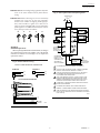
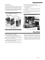
network is protected against interference by the arc gap
shown in Fig. 7.
The arc gap conducts at high voltage levels. It also glows
when it conducts, providing a visual indication that interference is occurring. This prevents the control from operating
and causes a shutdown.
Ignition interference (below the arcing level) can be
determined by measuring the flame current with ignition and
pilot on, and then with only pilot on. Any significant difference may indicate interference.
TESTING FLAME DETECTING FUNCTION
11. Observe the flame relay (right relay) for pull-in when
flame is established.
a. Flame relay pulls in; proceed to step 13.
b. Flame relay does not pull in; proceed to step 12.
12. Check the flame relay with a 121708 Flame Simulator
if available (follow the instructions with the simulator), or
check the following:
a. Perform a flame current check according to the flame
current check section.
b. If the current is satisfactory, replace the RA890.
c. If the current is not satisfactory, check all items listed
in the Flame Current Check section.
IMPORTANT: When an RA890F replaces an RA890E,
there may be installations where ignition interference
is not sufficient to destroy the RA890E, but is sufficient
to prevent operation of the RA890F due to its arc gap
protection. Be very suspicious of ignition interference
on any installation where the RA890E operates and
the RA890F does not.
OBSERVE SEQUENCING OPERATION
13. Observe the second stage oil valve or main gas valve
for opening when flame relay pulls in.
a. If valve does not open, check for line voltage at terminals 2-5.
(1) Normal voltage—check valve and valve circuit.
(2) Zero voltage—clean relay contacts. Replace the
RA890 if this does not correct the problem.
14. Observe ignition for cutoff when flame relay pulls in
when connected to terminal 4.
a. If ignition stays on and wiring checks out, replace the
RA890.
HOW TO ELIMINATE INTERFERENCE
(Tabulated in Order of Importance)
1. Provide adequate flame grounding area.
2. Be sure the ignition electrode and the flame rod are on
opposite sides of the grounding area.
3. Check for correct spacing on the ignition electrode.
Spacing should be 1/16 in. to 3/32 in. (1.6 to 2.4 mm) for
6,000V systems and 1/8 in. (3.2 mm) for 10,000V systems.
4. Eliminate any marginal spacing at other areas along
the lead routes. Replace any deteriorated leads.
MISCELLANEOUS PROBLEMS
Relay Chatter
Load relay chatter can result from extreme low voltage
(notify power company) or from a loose connection (tighten).
Flame relay chatter may result from improper combustion (adjust burner) or soot or carbon on flame detector
(clean, and correct the cause).
11
60-2034—7