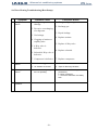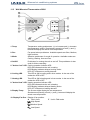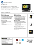
1
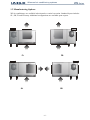
Service Manual And Advanced air conditioning systems Advanced air conditioning systems WS Series Contents SAFETY FIRST! ………………………………………………………………… 4 1. INTRODUCTION ……………………………………………………………….. 5 2. TECHNICAL DATA TABLES ……………...…………………………………. 8 3. WATER SOURCE CONSOLE UNITS ………………………………………... 11 4. SPLIT CONDENSER UNITS ..…………………………………………………. 12 5. HEATING ELEMENT RECOMMENDATIONS …………………………….. 13 6. REFRIGERATION CYCLE DIAGRAMS ……………………………………. 14 7. INSTALLATION INSTRUCTIONS …………………………………………... 16 8. INSTALLING THE CONTROL SYSTEM AND CONNECTING POWER... 22 9. ELECTRICAL WIRING DIAGRAMS ………………………………………... 25 10. TROUBLESHOOTING GUIDE ……………………………………………….. 31 11. CONTROL PROGRAMS and OPERATION INSTRUCTIONS ……………. 37 -3- Advanced air conditioning systems WS Series SAFETY FIRST! Safe operation is UNIQUE's number-one priority when designing products. Please read all the safety information and the instructions completely prior to beginning the installation and operation of the unit. UNIQUE products are designed for HVAC use. Using this equipment for any other purpose or in a way not within the operation recommendations specified in this manual will void the warranty and may cause injury. This manual is designed to provide comprehensive installation/operation information for this UNIQUE product. The table of contents provides a convenient overview of the information in this manual. Follow Safety Instructions! Carefully read all safety messages in this manual and on the equipment. Follow recommended practices and safe operating practices. Keep Safety Signs in good condition. Replace missing or damaged Safety Signs. Danger! In plannig the location of the equipment, take into consideration any areas that could present an unsafe situation. Avoid power lines that could come into contact with the equipment. Warning! – Electrical Safety. To avoid electrical shock, place equipment in a safe area, use guards around control panels and always shut off and lock out control boxes when working on equipment. In selecting electrical equipment to be used with the installation, you must use equipment conforming to applicable local or international codes or regulations. Important! Check all equipment for warning, danger and Caution Decals, before equipment is operated. Do not by-pass or take shortcuts with electrical safety equipment. Make sure electrical equipment is properly installed and grounded by a qualified electrician, and that it meets and adheres to all local laws and codes. Be sure covers, guards and safety devices are correctly installed and in proper position. Danger! Failure to follow proper assembly and operational procedures may cause damage to equipment or personal injury. -4- Advanced air conditioning systems WS Series 1. INTRODUCTION This Service Manual provides comprehensive technical documentation for all models of UNIQUE-WS split and packaged water source air conditioners. The information contained in the manual is useful for application engineers, architects, system designers, contractors and various level service and installation personnel. The manual also contains information about the optional features offered by the UNIQUE-WS series, as well as helpful information on electrical wiring diagrams and refrigeration cycle diagrams for the various models. Product specifications are subject to change without notice. Appearance of products may differ slightly from manual images. 1.1 Product Overview Unique-WS air conditioners are operating with water cooled condensing unit and can be utilized in applications such as residential, industrial and commercial buildings, offices, schools and other facilities. The operation of Unique-WS air conditioners is quiet and durable with low maintenance requirements and provides efficient year-round cooling and heating. The units are suitable for cooling tower installations, ground water sources or open water circuits. Unique-WS air conditioners feature heat pump facilities for heating, utilizing a 4-way reversing valve which switches the unit into heating mode. In heating mode adequate temperature of the cooling water must be insured. Alternatively, electric heating elements can be used for heating. In such configuration the units are equipped with additional protection elements. Scope of supply includes package units and split condenser units. Unique-WS appliances are adequate for ambient temperature range of minimum 19ºC and maximum 35ºC and water input temperature range of minimum 16ºC and maximum 35ºC. All Unique-WS air conditioners are ISO-9001:2000 and CE certified. -5- WS Series Advanced air conditioning systems 1.2 Manufacturing Options WS air conditioners are available in horizontal or vertical execution. Standard layout includes SL, SR, FL and FR setup. Additional configurations are available upon request. FL FR SL SR -6- Advanced air conditioning systems WS Series 1.3 Nameplate Information Technical information for a specific unit appears on the unit nameplate, which is attached to the indoor and/or the outdoor units. The unit nameplate includes the following information: MODEL Air-conditioner model name CLIMATE CLASS Class T1 – Standard conditions. VOLT/PHASE/Hz A/C power supply, for example: 400/3/50 = 400V/3 Phase/50 Hz. COS φ Power factor for the unit. FUSE Required fuse size, Amp. CAPACITORS μF Compressor capacitor, Fan capacitor (wherever applicable) AIR FLOW m³/h Air Flow at High Speed in m³/h AIR FLOW cfm Air Flow at High Speed in cfm WATER FLOW m³/h Water Flow in m³/h WATER FLOW gpm Water Flow in gpm REFRIGERANT Type and Quantity of refrigerant charge, Gr. CAPACITY W CAPACITY BTU/H Cooling capacity in Watts. Cooling capacity in BTU/Hr. INPUT POWER Power consumption in cooling and heating modes, watts. AMP. Current consumption in cooling and heating modes, Amp. -7- WS Series Advanced air conditioning systems 2.1 Technical Data Table – WS Package Units H L W Model Cooling capacity Heating capacity (1) (1) Power (2) Consumption Operating (2) Current C.O.P WS-15 WS-22 WS-28 3795 4440 6419 8353 Btu/h 12950 15150 21900 28500 Watt 5833 6532 9754 10910 Btu/h 19902 22286 33279 37223 Cooling Watt 981 1139 1672 1993 Heating Watt 1144 1256 1840 2058 Cooling Amp. 6 6.5 9.1 10.7 Heating Amp. 6 6.4 8.9 10.9 Cooling 3.9 3.9 3.8 4.2 Heating 4.1 4.2 4.3 4.3 3 M /h 680 850 1190 1530 CFM 400 500 700 900 mm H2O 5 5 6 6 3 1.1 1.2 1.4 1.7 Air Flow Net Static Pressure WS-12 Watt (3) Water Flow Heat Rejection-Cooling Heat Extraction-Heating Power Supply M /h GPM 4.8 5.3 6.1 7.5 Watt 4776 5579 8090 10346 Btu/h 16297 19037 27604 35300 Watt 4689 5276 7913 8851 Btu/h 16000 18000 27000 30200 V/Ph/Hz 230/1/50 (4) 230/1/50 (4) 230/1/50 (4) 230/1/50 (4) Time Delay Fuse Amp. C10 C10 C16 C16 Water Piping in/out BSP 3/4" 3/4" 3/4" 1" Drain mm 19 19 19 19 Refrigerant Charge gr. 1020 1300 1900 2400 Dimensions (LxWxH) mm 880x600x400 880x600x400 880x600x400 960x600x420 Net Weight Kg. 63 65 75 89 1. Design data for cooling: Air entering temperature 27ºC db/19ºC wb and water inlet temperature 29ºC Design data for heating: Air entering temperature 21ºC and water inlet temperature 20ºC 2. Excluding electrical heating element. 3. Net static pressure available at fan discharge at nominal capacity. 4. Available also in 400/3/50. Data applicable to R407C and may vary up to 3% for R22. For additional information contact Unique ltd. Product specifications are subject to change without notice. Appearance of products may differ slightly from catalog. -8- WS Series Advanced air conditioning systems 2.1 Technical Data Table – WS Package Units (continued) H L W Model Cooling capacity Heating capacity (1) (1) Power (2) Consumption Operating (2) Current C.O.P WS-43 WS-48 WS-54 WS-61 10551 12749 14068 15826 17878 Btu/h 36000 43500 48000 54000 61000 Watt 14269 17087 18893 20720 23740 Btu/h 48686 58300 64463 70695 81000 Cooling Watt 2590 3129 3529 3857 4266 Heating Watt 2692 3224 3565 3985 4396 Cooling Amp 13.5 17 3x7.1 3x7.5 3x7.7 Heating Amp 13.9 17.3 3x7.2 3x7.7 3x7.8 4.1 4.1 4.0 4.1 4.2 Cooling Heating Air Flow Net Static Pressure WS-36 Watt (3) Water Flow Heat Rejection-Cooling Heat Extraction-Heating Power Supply 4.3 4.3 4.3 4.2 4.4 M /h 3 2040 2550 2720 3060 3400 CFM 1200 1500 1600 1800 2000 mm H2O 7 6 6 13 13 M /h 3 2.2 2.6 3.1 3.4 3.6 GPM 9.6 11.4 13.6 14.9 15.8 Watt 13141 15879 17597 19684 22144 Btu/h 44837 54178 60042 67161 75555 Watt 11577 13863 15328 16735 19343 Btu/h V/Ph/Hz 39500 230/1/50 47300 (4) C20 230/1/50 (4) C25 52300 57100 66000 400/3/50 400/3/50 400/3/50 3xC16 3xC16 3xC16 Time Delay Fuse Amp. Water Piping in/out BSP 1" 1" 1" 1" 1" Drain mm 19 19 19 22.2 22.2 Refrigerant Charge gr. 3000 3800 4100 4500 5200 Dimensions (LxWxH) mm 1040x600x460 1290x600x520 1290x600x520 1370x700x560 1420x700x560 Net Weight Kg. 103 110 120 132 140 1. Design data for cooling: Air entering temperature 27ºC db/19ºC wb and water inlet temperature 29ºC Design data for heating: Air entering temperature 21ºC and water inlet temperature 20ºC 2. Excluding electrical heating element. 3. Net static pressure available at fan discharge at nominal capacity. 4. Available also in 400/3/50. Data applicable to R407C and may vary up to 3% for R22. For additional information contact Unique ltd. Product specifications are subject to change without notice. Appearance of products may differ slightly from catalog. -9- WS Series Advanced air conditioning systems 2.1 Technical Data Table – WS Package Units (continued) H L L W WS-75 to WS-102 Model Cooling capacity Heating capacity (1) (1) Power (2) Consumption Operating (2) Current C.O.P WS-75 WS-85 WS-102 WS-120 WS-144 Watt 21981 24912 29894 34402 42292 Btu/h 75000 85000 102000 120800 144800 Watt 28344 32187 39339 45830 53394 Btu/h 96709 109821 134226 156371 174800 Cooling Watt 5282 5743 7133 8629 10234 Heating Watt 5249 6073 7423 8813 10897 Cooling Amp 3x10.2 3x13.1 3x17 3x22 3x27 Heating Amp 3x10.4 3x13.3 3x17.3 3x22 3x27 Cooling 4.2 4.3 4.2 4.1 4.1 Heating 4.4 4.3 4.3 4.2 3.9 3 M /h 4250 4760 5440 6800 8160 Air Flow Net Static Pressure WS-120 and WS-144 (3) Water Flow Heat Rejection-Cooling CFM 2500 2800 3200 4000 4800 mm H2O 18 12 14 14 14 3 4.4 5.2 6.3 7.3 8.5 M /h GPM 19.3 22.8 27.6 32 37.3 Watt 27263 30655 37027 44033 52526 Btu/h 93021 104596 126337 150241 179219 Watt 23095 26144 31917 37016 42497 Btu/h 78800 89100 108900 126300 145000 V/Ph/Hz 400/3/50 400/3/50 400/3/50 400/3/50 400/3/50 Time Delay Fuse Amp. 3xC20 3xC20 3xC25 3xC40 3xC40 Water Piping in/out BSP 1¼" 1¼" 1¼" 1½" 1½" Drain mm 22.2 22.2 22.2 30 30 Refrigerant Charge gr. 6100 7300 8500 10300 12200 Dimensions (LxWxH) mm 1510x700x600 1540x750x610 1620x750x610 2050x1000x630 2050x1100x660 Net Weight Kg. 160 180 190 250 320 Heat Extraction-Heating Power Supply 1. Design data for cooling: Air entering temperature 27ºC db/19ºC wb and water inlet temperature 29ºC Design data for heating: Air entering temperature 21ºC and water inlet temperature 20ºC 2. Excluding electrical heating element. 3. Net static pressure available at fan discharge at nominal capacity. 4. Available also in 400/3/50. Data applicable to R407C and may vary up to 3% for R22. For additional information contact Unique ltd. Product specifications are subject to change without notice. Appearance of products may differ slightly from catalog. - 10 - WS Series Advanced air conditioning systems 3. Technical data table – WSC – Water Source Console H L W Model Cooling capacity Heating capacity (1) (1) Power (2) Consumption Operating (2) Current C.O.P WSC-15 WSC-22 WSC-28 3795 4440 6419 8353 Btu/h 12950 15150 21900 28500 Watt 5833 6532 9754 10910 Btu/h 19902 22286 33279 37223 Cooling Watt 981 1139 1672 1993 Heating Watt 1144 1256 1840 2058 Cooling Amp. 6 6.5 9.1 10.7 Heating Amp. 6 6.4 8.9 10.9 3.9 3.9 3.8 4.2 Cooling Heating Air Flow Net Static Pressure WSC-12 Watt (3) Water Flow Heat Rejection-Cooling Heat Extraction-Heating Power Supply 4.1 4.2 4.3 4.3 M /h 3 680 850 1190 1530 CFM 400 500 700 900 mm H2O 5 5 6 6 M /h 3 1.1 1.2 1.4 1.7 GPM 4.8 5.3 6.1 7.5 Watt 4776 5579 8090 10346 Btu/h 16297 19037 27604 35300 Watt 4689 5276 7913 8851 Btu/h V/Ph/Hz 16000 230/1/50 18000 (4) 230/1/50 27000 (4) 230/1/50 30200 (4) 230/1/50 (4) Time Delay Fuse Amp. C10 C10 C16 C16 Water Piping in/out BSP 3/4" 3/4" 3/4" 1" Drain mm 19 19 19 19 Refrigerant Charge gr. 1020 1300 1900 2400 Dimensions (LxWxH) mm 1100x350x700 1100x350x700 1350x350x700 1350x350x700 Net Weight Kg. 62 65 75 75 1. Design data for cooling: Air entering temperature 27ºC db/19ºC wb and water inlet temperature 29ºC Design data for heating: Air entering temperature 21ºC and water inlet temperature 20ºC 2. Excluding electrical heating element. 3. Net static pressure available at fan discharge at nominal capacity. 4. Available also in 400/3/50. Data applicable to R407C and may vary up to 3% for R22. For additional information contact Unique ltd. Product specifications are subject to change without notice. Appearance of products may differ slightly from catalog. - 11 - WS Series Advanced air conditioning systems 4. Dimensions and Weights – Split Condenser Units H L W Model WS-12 LxWxH Refrigerant Tubing Connections Water Inlet Weight mm Liquid Small inch Suction Large inch BSP Kg 600x350x400 3/8" 1/2" 3/4" 35 WS-15 600x350x400 3/8" 1/2" 3/4" 38 WS-22 600x350x400 3/8" 5/8" 3/4" 45 WS-28 600x350x420 3/8" 5/8" 1" 61 WS-36 600x400x460 3/8" 5/8" 1" 68 WS-43 650x450x520 1/2" 3/4" 1" 68 WS-48 650x450x520 1/2" 3/4" 1" 70 WS-54 650x450x520 1/2" 3/4" 1" 71 WS-61 750x480x560 1/2" 7/8" 1" 73 WS-75 750x480x520 1/2" 7/8" 1¼" 75 WS-85 750x550x610 1/2" 7/8" 1¼" 95 WS-102 750x550x610 1/2" 7/8" 1¼" 100 WS-120 850x550x630 5/8" 1⅛" 1½" 135 WS-144 1000x550x660 5/8" 1⅛" 1½" 150 Data applicable to R407C and may vary up to 3% for R22. For additional information contact Unique ltd. Product specifications are subject to change without notice. Appearance of products may differ slightly from catalog. - 12 - WS Series Advanced air conditioning systems 5. Heating Element Recommendations Model Heating Element Kw WS-12 1.5 WS-15 WS-22 1-Ph Units 3-Ph Units Current Amp. 6.8 Fuse Amp. 10 Current Amp. 3x2.2 Fuse Amp. 3x6 2 9.1 10 3x3.1 3x6 3 13.7 16 3x4.6 3x6 WS-28 4 18.2 20 3x6.1 3x10 WS-36 5 22.8 25 3x7.6 3x10 WS-43 6 27.3 32 3x9.1 3x16 WS-48 6 - - 3x9.1 3x16 WS-54 8 - - 3x12.2 3x16 WS-61 9 - - 3x13.7 3x16 WS-75 9 - - 3x13.7 3x16 WS-85 10 - - 3x15.2 3x20 WS-102 12 - - 3x18.2 3x20 WS-120 14 - - 3x20.3 3x25 WS-144 17 - - 3x26 3x32 Data applicable to R407C and may vary up to 3% for R22. For additional information contact Unique ltd. Product specifications are subject to change without notice. Appearance of products may differ slightly from catalog. - 13 - Advanced air conditioning systems 6.1 Refrigeration Cycle – Cooling Only - 14 - WS Series Advanced air conditioning systems 6.2 Refrigeration Cycle – Heat Pump - 15 - WS Series Advanced air conditioning systems WS Series 7. INSTALATION INSTRUCTIONS 7.1 General All parts and accessories are packed and shipped with appropriate measure to ensure that everything is protected during transportation. The installation team must be familiar with the installation requirements, to exercise due care in handling and to prevent damage to the equipment. The following instructions are in addition to any state and municipal regulations which may apply. These instructions do not cover all features concerning HVAC installation or methods of procedure. The appliance shall be installed in accordance with the national wiring regulations. The installation must be performed in accordance with manufacturer's specifications using only approved piping, original cables and original accessories. Note: The appliance is classified as a stationary class I motor-operated appliance. 7.2 Electrical Requirements The appliance is stationary and shall be connected to the electrical supply by fixed wiring. The air conditioner must be directly connected to an appropriate power supply. Use only fuses as specified in the data tables. Use only a single length power cable, without extensions. If the supply cord is damaged, it must be replaced by a qualified electrician and in accordance with national wiring regulations. Cable and conduit entries shall be suitable for cables or conduits having maximum overall diameters of 14 mm and 16 mm (23 mm in USA and Canada), respectively. Introduction of conduit or cable does not reduce clearances below 2 mm for basic supplementary insulation and 2 mm for functional insulation. Supply cord shall not be lighter than each of the following (a lower number in the code designation of the cord in IEC 60227 or IEC 60245 indicates a lighter type): a. Ordinary tough rubber sheathed cord (code designation 60245 IEC 53) b. Light polyvinyl chloride sheathed cord (code designation 60227 IEC 53) Nominal cross-sectional area for conductors of supply cord (cable for fixed wiring) shall be 2.5-6 mm². Supply cord shall not be in contact with sharp points or edges of the appliance. The supply cord shall have a green/yellow core that is connected to the earthing terminal of the appliance and to the earth contact of the outlet. Conductors of supply cords shall not be consolidated by lead-tin soldering where they are subjected to contact pressure, unless the clamping means is constructed so that there is no risk of bad contact due to cold flow of the solder. Mounting the cord to part of the enclosure shall not damage the insulation of the supply cord. Chord anchorages shall be arranged so that they are only accessible with the aid of a tool or shall be constructed so that the cord can only be fitted with the aid of a tool. The insulated conductors of the supply cord shall be additionally insulated from accessible metal parts by basic insulation. This insulation may be provided by the sheath of the supply cord or by other means. - 16 - Advanced air conditioning systems WS Series The arrangement of the terminals, or the length of the conductors between the cord anchorage and the terminals, shall be such that the current carrying conductors become taut before the earth conductor if the cord slips out of the cord anchorage. Conditional connection to power network provides not more than 0.09 ohm of power system impedance. Important! Means for disconnecting from the supply mains, having a contact separation in all poles that provide full disconnection under overvoltage category III, shall be incorporated in the fixed wiring and directly connected to the supply terminals, in accordance with the wiring rules. Important! Means for disconnection from supply mains must be incorporated in the fixed wiring in accordance with the national wiring regulations. Important! The control wires between the main control box and the wall mounted thermostat utilize low voltage 12V DC. The supply (mains) cable and control wire (flat cable between the wall mounted thermostat Alfa 261 and electrical box) shall be passed in separate (different) ducts and not in proximity to each other. Note: Main circuit breaker and power supply must always be ON in models that their compressor is equipped with oil heating element. If disconnected, make sure that power supply was ON for at least 6 hours before starting the unit. Note: The appliance is suitable for indoor use only. Warning! Failure to comply with these instructions may cause malfunction of the unit. Important! In case where an electrical valve for entering or exiting cooling water is being used - verify that valve is open before the compressor starts. - 17 - WS Series Advanced air conditioning systems 7.3 Typical WS Installation 5 11 12 3 2 10 3 6 8 9 4 1 7 Fig. 7-1 1. Rubber Shock Absorbers. 2. Strainer. 3. PTFE or Rubber ring. 4. Flexible hose. 5. Cut-Off Valves. 6. Rubber Joints (Siphon, T-Connection and Drain Hose). - 18 - 7. Control Unit. 8. Electrical cable. 9. Acoustic Insulation. 10. Hanger Mounting Brackets. 11. Hanger Anchors. 12. Air Vent Plug. Advanced air conditioning systems WS Series 7.4 Unit Location and Installation Install the unit in a location with convenient access to the service panels, air filter and control box. See Fig. 7-2 for minimum permissible distances to adjacent structures. Protect the unit from any heat source. Make sure that the unit is level. For all models, hanging installation is commonly used. Installing the unit resting on a rigid surface is allowed. Carefully plan the drainage hose path at a minimum slope of 2%, avoiding sharp bends or water traps. Fig. 7-2 7.4.1 Installing the Unit Directly On the Ceiling (Fig. 7-1) Select the installation location according to the above mentioned considerations and guidelines. Mark 4 holes on the ceiling, according to the unit's mounting bracket holes (10). Drill adequate holes and fix the long ceiling anchors (11) in position. Lift up the unit onto the hanger anchors through the mounting brackets. Insert four rubber shock absorbers on the four anchors, as shown in Fig. 7-1. Lock the assembly with the lock nut. Should the unit be installed on a rigid surface, stick four rubber absorbtion cushions on the four corners of the base. In any mode of installation it is recommended to place under the unit an acoustic insulation sheet (9). 7.5 Connecting the Water Piping Clearly identify the water supply piping. An external safeguard device shall be connected to the water source to limit its output pressure (in excess of atmospheric pressure) to 6 bar. Use flexible hoses (4) to connect the water piping according to Fig. 7-3. For piping size see technical data tables. Use only premium quality flexible hoses and make sure it withstands the system water pressure. (Note: Ample pressure hoses must be installed in tall buildings.) - 19 - WS Series Advanced air conditioning systems Connect the incoming water to the WATER IN connection and the return water to the WATER OUT connection. Use adequate thread sealant and also the supplied sealing ring (3). The supplied strainer (2) must be installed on the WATER IN connection. See Fig. 7-1. Install the strainer with the drain plug facing down, in a location with convenient service access. Complete the water piping installation and open the two cut-off valves (5). Allow water to flow in and out the unit. Carefully open the air vent plug (12). Release all air from the system and close the plug back. Inspect all connections for water leaks. It is common practice to leave open the two cut-off valves (5) throughout the rest of the installation and occasionally inspect the piping for leaks. Water out WS Unit 120-144 Water in Flexible tube to water system 1 1/2" Double fitting 1 1/2" Connector 1 1/2" Cupper adaptor screwing 1 1/2" Water out WS Unit 12-102 Water in Flexible tube to water system 3/4", 1", 1 1/4" Rubber seal 3/4", 1", 1 1/4" Fig. 7-3 - 20 - Cupper adaptor screwing 3/4", 1", 1 1/4" Advanced air conditioning systems WS Series 7.6 Connecting the Drain Hose Connect the supplied rubber siphon (6) to the drain hose connection. See Fig. 7-1 for details. The T- connection (breather, not supplied) and the drain hose (not supplied) immediately follow the siphon. 7.7 Connecting the Ducting Work To obtain optimal results, duct cross sections, connections, elbows and branches must be properly designed. We highly recommend seeking for expert advice on this matter. Use flexible sleeve to connect the ducting to the air conditioner. 7.8 Connecting the Temperature Sensor Bulbs See Fig. 7-4 for identification. The temperature sensor bulbs are factory pre-assembled. In case of replacement, make sure that the new bulb is fitted into the locating tube with touch-fit. . Fig. 7-4 - 21 - Advanced air conditioning systems WS Series 8. INSTALLING CONTROL SYSTEM and CONNECTING POWER 8.1 Installing the Thermostat (Fig. 8-1) To WS electrical box Fig. 8-1 Remove the thermostat from the packaging. Install the in-room wall mounted thermostat: Separate the front panel from the back panel by depressing the tongue lock located in the back part of the unit. Push the back panel out. Gently disconnect the data cable from its quick connect wiring harness. Line the back panel up against the wall or against any other flat surface onto which it is to be mounted. Drill holes and use appropriate fixing screws to fasten the panel to its location. Locate the terminal box. See Fig. 8-2 and Fig. 8-3. Complete the electrical connections according to the electrical wiring diagrams. Reconnect the data cable and close back the cover of the thermostat to its base. - 22 - Advanced air conditioning systems 8.2 Terminal Box Location – Single Phase Unit N GR ONLY FOR UNITS WITH ELECTRICAL HEATING ELEMENTS Fig. 8-2 - 23 - WS Series Advanced air conditioning systems 8.3 Terminal Box Location – 3 Phase Unit ONLY FOR UNITS WITH ELECTRICAL HEATING ELEMENTS Fig. 8-3 - 24 - WS Series WS Series Advanced air conditioning systems 9. Electrical Wiring Diagrams 9.1 Electrical Wiring Diagram – Single Phase Cooling Only – Model 260U HP – High pressure control LP – Low pressure control CC – Compressor contactor WS Type 12 15 22 MAIN POWER Cable 2.5 2.5 2.5 Cross Section Area mm² ALFA 123U – Power switch unit ALFA 260U – Room Thermostat 28 36 43 48 54 61 75 4 4 6 - - - - - 25 - 85 102 120 144 - - - - WS Series Advanced air conditioning systems 9.2 Electrical Wiring Diagram – 3 Phase Cooling Only – Model 260U HP – High pressure control LP – Low pressure control CC – Compressor contactor ALFA 123U – Power switch unit ALFA 260U – Room Thermostat WS Type 12 15 22 28 36 43 48 54 61 MAIN POWER Cable 2.5 2.5 2.5 2.5 2.5 2.5 2.5 2.5 2.5 Cross Section Area mm² - 26 - 75 85 102 120 144 4 4 6 10 10 WS Series Advanced air conditioning systems 9.3 Electrical Wiring Diagram – Single Phase with Electrical Heating Elements – Model 260U HP – High pressure control LP – Low pressure control ALFA 260U – Room Thermostat ALFA 123U – Power switch unit WS Type 12 15 22 MAIN POWER Cable 2.5 2.5 2.5 Cross Section Area mm² CC – Compressor contactor CH1, CH2 – Heaters contactor TS1, TS2 – Safety thermostat 28 36 43 48 54 61 75 4 4 6 - - - - - 27 - 85 102 120 144 - - - - WS Series Advanced air conditioning systems 9.4 Electrical Wiring Diagram – 3 Phase with Electrical Heating Elements – Model 260U HP – High pressure control LP – Low pressure control ALFA 260U – Room Thermostat ALFA 123U – Power switch unit CC – Compressor contactor CH1, CH2 – Heaters contactor TS1, TS2 – Safety thermostat WS Type 12 15 22 28 36 43 48 54 61 MAIN POWER Cable 2.5 2.5 2.5 2.5 2.5 2.5 2.5 2.5 2.5 Cross Section Area mm² - 28 - 75 85 102 120 144 4 4 6 10 10 WS Series Advanced air conditioning systems 9.5 Electrical Wiring Diagram – Single Phase with Heat Pump – Model 260U HP – High pressure control LP – Low pressure control ALFA 260U – Room Thermostat WS Type 12 15 22 MAIN POWER Cable 2.5 2.5 2.5 Cross Section Area mm² ALFA 123U – Power switch unit CC – Compressor contactor RV1 – 4 way valve 28 36 43 48 54 61 75 4 4 6 - - - - - 29 - 85 102 120 144 - - - - WS Series Advanced air conditioning systems 9.6 Electrical Wiring Diagram – 3 Phase With Heat Pump – Model 260U HP – High pressure control LP – Low pressure control ALFA 260U – Room Thermostat ALFA 123U – Power switch unit CC – Compressor contactor RV1 – 4 way valve WS Type 12 15 22 28 36 43 48 54 61 MAIN POWER Cable 2.5 2.5 2.5 2.5 2.5 2.5 2.5 2.5 2.5 Cross Section Area mm² - 30 - 75 85 102 120 144 4 4 6 10 10 WS Series Advanced air conditioning systems 10. TROUBLESHOOTING GUIDE 10.1 Troubleshooting Notes. Important! Reset: Once the unit has stopped due to failure, restart is possible after resetting. Reset the system by pressing ON/OFF button on the room thermostat. Call the technician for assistance should the failure be repeated. Note: Check for broken wires and loose cable lugs first! Warning: Always unplug the A/C before performing cleaning or maintenance activities. 10.2 Failure Code Troubleshooting. Display 1 2 3 ER2 Return Air Sensor failure. Unit continues running. ER3 Evaporator coil sensor failure. Unit continues running. ER4 Possible Cause Corrective Action Short, disconnected or faulty return air sensor. Check return air sensor. Replace sensor if faulty. Short, disconnected or faulty evaporator coil sensor. Check evaporator coil sensor. Replace sensor if faulty. Short, disconnected or faulty water temperature sensor. Check water temperature sensor. Replace sensor if faulty. Only for Heat Pump Water temperature sensor failure Unit continues running. - 31 - WS Series Advanced air conditioning systems Failure Code Troubleshooting (continued). Display 4 Possible Cause Corrective Action 1. Clogged air filter 1. Clean filter. 2. Faulty fan capacitor. 2. Replace capacitor. 3. Faulty fan motor. 3. Replace fan motor. 4. Air discharge shutters are too closed. 4. Open air discharge shutters. 5. Lack of refrigerant. 5. Check for leaks and add refrigerant. ER5 Gas pressure too low 6. Condenser cooling water is too cold. 5 1. Clogged water strainer. 1. Clean strainer. 2. Condenser cooling water too warm. 2. Check cooling tower (or the cooling water source) for proper operation. 3. No water circulation in heat exchanger. 3. a. Check cooling tower (or the cooling water source) for proper operation. b. Heat exchanger is clogged. Clean the heat exchanger or replace it. 1. No air supply at indoor side. 1. See troubleshooting guide section 10.3 item 4 2. Indoor fan is not running. 2. See troubleshooting guide section 10.3 item 7 3. Air shutters are closed. 3. Open air shutters. 1. Lack of water or low water flow. 1. Check water filter. ER6 Gas pressure too high 6 6. Check cooling tower (or the cooling water source) for proper operation. ER7 Only for units with electrical heating elements. Heating elements protection. 7 ER8 Only for Heat Pump Water temperature too cold. - 32 - WS Series Advanced air conditioning systems 10.3 General Troubleshooting. Symptom 1 2 3 4 A/C fails to start. Only indoor fan motor works although cooling or heating is desired. Only fan motor is working. No cooling and/or heating take place. No air supply at indoor unit Probable Cause Corrective Action 1. Power supply to unit not connected (display is blank). 1. Check for proper connection of power plugs in wall socket. Check red LED on RST Controller (wherever applicable): If LED is OFF – change RST wires. If LED is ON – check Phase voltage. 2. Fuse Blown (display is blank). 2. Reset automatic circuit breaker or replace line fuse. 3. Electric supply wall socket is defective. 3. Repair or replace wall socket. 1. The selected mode is on Fan Only, or on Cool when heating is desired. 1. Check if the room thermostat is on the desired mode. If not, select the correct mode (refer to your User Manual). 2. Temperature is set to a value which is too high (in Cool mode). 2. Observe the temperature setting on the room thermostat. 3. Faulty compressor. 3. Replace compressor. 1. Overload safety device on compressor is cut out due to high temperature. 1. Switch Off power and try again after one hour. 2. Compressor run capacitor is burnt. 2. Replace compressor run capacitor. 3. Compressor winding shorted. 3. Replace compressor. 1. Indoor fan motor is blocked or turns slowly. 1. Check voltage. Repair wiring if necessary. Check indoor fan wheel if tight on motor shaft. Tighten if necessary. 2. Replace indoor fan motor capacitor. 2. Indoor fan motor capacitor is burnt. 3. Indoor fan motor winding is burnt. 3. Replace indoor fan motor. 4. Clogged air filters. 4. Clean filters. - 33 - WS Series Advanced air conditioning systems General Troubleshooting (continued). Symptom 5 Low Capacity. 6 Water accumulates and overflows from evaporator drain pan. 7 Indoor fan is not running at all. 8 Compressor motor is not running at all Probable Cause Corrective Action 1. Lack of refrigerant causes ice formation on the evaporator coil (in Cool mode). 1. Unit must be charged (according to the nameplate) after localizing the gas leak. 2. Clogged air filters. 2. Clean filters. Drain pan pipe or hose is clogged or the spout of drain pan is clogged. Disassemble plastic drain-pipe from spout of evaporator drain pan. Flush with clean water. 1. Failure in motor capacitor. 1. Replace the capacitor. 2. No voltage out of P.C.B. assembly for fan motor. 2. Replace the P.C.B. assembly. 3. Motor winding failure (check resistance). 3. Replace the fan motor. 1. Failure in compressor motor magnetic contactor. 1. Replace faulty contactor. 2. Compressor motor winding failure (check resistance). 2. Replace the compressor. - 34 - WS Series Advanced air conditioning systems 10.4 Poor Cooling Troubleshooting. Symptom 1 2 3 Refrigerant flow failure Air circulation failure. Freezing Conditions at Evaporator Coil Probable Cause Corrective Action 1. Refrigerant gas shortage. 1. Charge refrigerant gas. 2. Excessive overcharging of refrigerant. 2. Recharge gas. 3. Gas leakage. 3. Repair leakage. 4. Clogging of strainer or capillary tube. 4. Replace strainer. 5. 4-Way valve is defective. 5. Replace 4-Way valve. 6. Solenoid 4-Way valve is defective. 6. Replace solenoid. 7. Compressor is defective. 7. Replace compressor. 1. Air filter is clogged 1. Clean air filter. 2. Air shutters are closed. 2. Open air discharge shutters. 1. Clogged air filter 1. Clean filter. 2. Faulty capacitor. 2. Replace capacitor. 3. Faulty fan motor. 3. Replace fan motor. 4. Air discharge shutters are too closed. 4. Open air discharge shutters. 5. Lack of refrigerant. 5. Check for leaks and add refrigerant. - 35 - WS Series Advanced air conditioning systems 10.5 Poor Heating Troubleshooting (Heat Pump). Symptom 1 Refrigerant flow failure Probable Cause 1. Refrigerant gas shortage. Corrective Action 1. Charge refrigerant gas. 2. Recharge gas. 2. Excessive overcharging of refrigerant. 3. Repair leakage. 3. Gas leakage. 4. Replace strainer. 4. Clogging of strainer or capillary tube. 5. Replace 4-Way valve. 5. 4-Way valve is defective. 6. Replace solenoid. 6. Solenoid 4-Way valve is defective. 7. Compressor is defective. 7. Replace compressor. 2 Air circulation failure. 1. Air filter is clogged 1. Clean air filter. 2. Air shutters are closed. 2. Open air discharge shutters. 3 Heating elements failure. 1. One or two hating stages are not operating. 1. a. Check electrical heating elements (resistance). b. Check contactors. c. Check the elements` time delay fuse. 4 Refrigerant low pressure. 1. Lack of water flow. 1. Check water filter. - 36 - Advanced air conditioning systems WS Series 11. CONTROL PROGRAMS and OPERATION INSTRUCTIONS 11.1 General Protection: The air conditioner is protected by pressure and temperature sensors. The sensors cut off the unit once extreme and dangerous conditions are detected. The DISPLAY on the thermostat indicates the failure code as stipulated in the troubleshooting section. Restart after power failure: Back-up memory keeps the working data. Once power returns, the air conditioner will restart and return to its saved data. The unit can be modified to fail-safe manual restart after power failure (Start-Stop). Instructions for such modification are available upon request. Reset and restart after failure: Once the unit has stopped due to failure, restart is possible after resetting. Reset the system by pressing ON/OFF button on the room thermostat. Call the technician for assistance should the failure be repeated. Restart time delay: Compressor starting time delay is 1 min. at first start and 3.5 min. before each restarting. Timer accuracy is ±20 sec. Evaporator fan control (only for Heat Pump unit): In cooling mode the fan runs continuously. In heating mode the fan stops running 15 sec. after compressor stop. Evaporator fan control (only for units with electrical heating elements): In cooling mode the fan runs continuously. In heating mode the fan stops running 40 sec. after the heating elements are turned off. Water temperature control (only for Heat Pump unit): Compressor stops if water temperature reaches below 4ºC. Compressor restart enabled at water temperature above 10ºC. Failure in water temperature sensor does not stop unit operation. If failure occurs 3 times per hour and/or holds for 1 full hour, signal of failure ER8 will appear stable and On/Off press for re-start not allowed. Re-start only by shut-off and switch-on of power supply. Heating control (only for units with electrical heating elements): The return air temperature sensor switches ON the first heating group at room temperature 1ºC lower than the set temperature. Heating is switched OFF at set point. Second heating group is switched ON at room temperature 2ºC lower than the set temperature. Second heating group is switched OFF at 1ºC under set point. Evaporator coil temperature control: Compressor stops at coil temperature below 0ºC. Compressor restart enabled at coil temperature above 8ºC. Failure in evaporator coil temperature sensor does not stop unit operation. Return air temperature sensor: Thermostats include an incorporated, build-in temperature sensing element. However, an external sensor (optional) can be added. In such case the operation of the unit is governed by the external sensor. The thermostat temperature setting range is 16ºC to 30ºC. Failure in return air sensor will cause the compressor to run continuously. If unit was set to "AUTO" operation mode, the compressor will not run. If an external sensor is added, a system failure will occur only when both sensors are faulty. - 37 - Advanced air conditioning systems WS Series Air-Flow protection (only for units with electrical heating elements): To protect the heating elements from overheating or from operating without flowing air. A combination of differential pressure flow-switch and temperature sensor immediately cut off the heating elements in case the temperature or air-flow reaches the pre-set protection values. The fan continues running for additional 15 sec. Low pressure protection: Low pressure compressor protection. Set value is 2.7 bar (40 psi). The compressor stops after 2 min. time delay. At each compressor re-start the system ignores LP entrance for 2 min. At heat elements mode, LP protection is not active. High pressure protection: High pressure compressor protection. Set value is 24.8 bar (365 psi).The compressor stops immediately. At heat elements mode, HP protection is not active. 11.2 Modes of operation and uses Setting the Temperature The temperature may be adjusted within the range of 16ºC and 30ºC. Use temperature setting pushbuttons (+) to increase and (-) decrease the temperature. Cooling Mode In this mode the air conditioner cools, dries and filters the air in the room. The set temperature is maintained. Heating Mode In this mode the air conditioner heats and filters the air in the room. The set temperature is maintained. Auto Cooling/Heating Mode In this mode the air conditioner automatically selects the cooling or heating position according to room conditions and set temperature. Auto Ventilation Mode In this mode the air conditioner automatically changes the speed of the fan in accordance with the room temperature. At room temperature close to the set point the fan rotates at low speed while speed increases when room temperature is up. Display shows "A" Fan Only (Ventilation) Mode The air conditioner maintains continuous air flow, without cooling or heating. Display shows "F". - 38 - Advanced air conditioning systems WS Series 11.3 Wall Mounted Thermostats α 260U 1. Temp Temperature setting pushbuttons: (+) to increase and (-) decrease the temperature setting. Simultaneous pressing of both (+) and (-) buttons will display the actual room temperature. 2. Fan Fan speed select pushbutton. Available speeds are Slow, Medium, High and Auto. 3. Mode Selection pushbutton for mode of operation. Available modes are Cooling, Heating, Auto and Fan. 4. On/Off Pushbutton for turning the unit on and off. This pushbutton is also used for failure canceling. 5. "Active Cool" LED Cooling operation indicator LED. LED ON indicates that the unit is cooling. LED Blinking indicates delayed cooling action. LED OFF indicates no cooling demand. 6. Cooling LED This LED is ON in cooling and in Auto modes. In the rest of the modes the LED is OFF. 7. Heating LED This LED is ON in heating and in Auto modes. In the rest of the modes the LED is OFF. 8. "Active Heat" LED Heating operation indicator LED. LED ON indicates that the unit is heating. LED Blinking indicates delayed heating action. LED OFF indicates no heating demand. 9. Display-Temp. The first two digits display the set temperature. Simultaneous pressing of both (+) and (-) buttons will display the actual room temperature. 10. Display-Fan Pos. Display of fan position. A Fan in Auto High Speed Medium Speed Low Speed - 39 - F Unit in FAN mode Advanced air conditioning systems WS Series NOTES ……………………………………………………………………………………………………………………… ……………………………………………………………………………………………………………………… ……………………………………………………………………………………………………………………… ……………………………………………………………………………………………………………………… ……………………………………………………………………………………………………………………… ……………………………………………………………………………………………………………………… ……………………………………………………………………………………………………………………… ……………………………………………………………………………………………………………………… ……………………………………………………………………………………………………………………… ……………………………………………………………………………………………………………………… ……………………………………………………………………………………………………………………… ……………………………………………………………………………………………………………………… ……………………………………………………………………………………………………………………… ……………………………………………………………………………………………………………………… ……………………………………………………………………………………………………………………… ……………………………………………………………………………………………………………………… ……………………………………………………………………………………………………………………… ……………………………………………………………………………………………………………………… ……………………………………………………………………………………………………………………… ……………………………………………………………………………………………………………………… ……………………………………………………………………………………………………………………… ……………………………………………………………………………………………………………………… ……………………………………………………………………………………………………………………… ……………………………………………………………………………………………………………………… ……………………………………………………………………………………………………………………… ……………………………………………………………………………………………………………………… ……………………………………………………………………………………………………………………… ……………………………………………………………………………………………………………………… ……………………………………………………………………………………………………………………… - 40 - Unique – Engineering & Air Conditioning Mitzpe Sapir Industrial Park P.O.B. 13201 Tsur Igal 44862, ISRAEL Tel. 972-9-7498707, Fax. 972-9-7498708 E-mail: [email protected] WS-SM-EN-V03-R09 DEC 2008