1
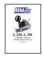
L-250, L-350
TABBER/LABELER
OPERATIONS MANUAL
Revised 2-19-08
Part #: M-3432
SAFETY PRECAUTIONS
THIS EQUIPMENT PRESENTS NO PROBLEM WHEN USED PROPERLY. HOWEVER,
CERTAIN SAFETY RULES SHOULD BE OBSERVED WHEN OPERATING THE
L-250/350.
READ THIS MANUAL CAREFULLY AND FOLLOW THE RECOMMENDED
PROCEDURES:
1. Keep hands, hair, and clothing clear of rollers and other moving parts.
2. Always turn off machine before making adjustments, cleaning the machine, or
performing any maintenance not covered in this manual.
3. Turn power off, including conveyor when not in use.
4. Never leave the machine in an alarm condition. Either reset the machine or turn off
the power.
CAUTION
THIS EQUIPMENT MUST BE CONNECTED TO A
PROPERLY GROUNDED OUTLET. FAILURE TO
DO SO CAN CAUSE ELECTRIC SHOCK!
SPECIFICATIONS
L-250 TABBER/LABELER
DIMENSIONS:
SPEED – TABBER:
SPEED – LABLER
MEDIA SIZE:
MEDIA THICKNESS:
TAB SIZE:
TAB TYPES
16 1/2" W x 19" H x 18" L
Variable from 5,000 - 20,000 per hour ( Tri-folded 60 lb.
Offset Stock)
Variable from 5,000 - 20,000 per hour ( No.10
envelopes )
Postcards 20,000 per hour
9" x 12" flats 12,000 per hour
Length – 3 5/8” min., 18" max.
Width - 5" min., 16" max.
Label: single 20lb sheet min. - up to 5/16" max.
Tab: folded 20lb piece min. - up to 1/8” max.
Length - 3/8" to 11/4", Width - 1/2" to 2"
Paper, *Clear, *Translucent
* must have engineered backing (black area below tab)
LABEL SIZE:
FEEDER:
HOPPER CAPACITY:
ZIP SORT:
COUNTER:
ELECTRICAL:
SHIPPING WEIGHT:
Length - 3/8" min., 15" max, Width - 1/2" min., 6 1/2" max.
Automatically compensates for most color labels and
backing
Top-load, bottom-feed for continuous operation.
Postcards 800
No.10 envelopes 250
9"x12"flats 250
Switch selectable electronic sensor (labeler only)
Resettable 5-digit LCD
110 VAC /60 Hz 2 Amp (220 VAC / 50 Hz available)
70 Ibs /32 kg
NOTE: There are two types of tabs/labels used commercially. One is designed for hand,
and the other is for machine application. Use tabs/labels designed ONLY for machine
application with the Tabber/Labeler. Avoid using tabs/labels with little or no contrast
between tab/label and backing. Less than 2 clicks on the tab/label sensitivity adjustment
will not allow unit to run properly. Doubles and misfeeds are a symptom of the wrong label
being used.
OPTIONAL REEL-FEED SYSTEM
CAPACITY:
10,000 Tabs
L-350 TABBER/LABELER/STAMP AFFIXER
The specifications for the L-350 are the same as for the L-250 with the exception that
the L-350 can apply stamps from a roll, to pieces up to 9.5 inches long.
-1-
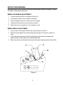
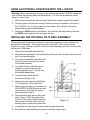
ASSEMBLING THE L-250/350
1. Remove all packing and parts supplied. Check and identify all parts with the ones
listed below.
•
Envelope Guide
90-102-05
•
Stack Rest
90-102-10
•
Media Support
90-102-13
•
Thumbscrews
90-109-07
•
Tray Assembly
90-104-03
•
Power Cord
123-635
Figure 1
2. Mount envelope guide [Figure1A] to side guide block using 2 screws [Figure 1B].
3. Mount media stack rest [Figure 1C] to the machine using thumbscrew {Figure 1D].
4. Mount label stack tray [Figure 1E] on cross rods [Figure 1F]. The assembly snaps
into place.
5. Plug power cord into socket on the back of the machine. Plug other end into 115 VAC
GROUNDED outlet.
THIS STEP CONCLUDES INITIAL INSTALLATION OF THE L-250/350.
-2-
SETUP PROCEDURES
BEFORE USING THE L-250/350, SEVERAL ADJUSTMENTS MUST BE MADE TO SET
UP MEDIA THICKNESS AND SIZE
MEDIA THICKNESS ADJUSTMENT
1. Loosen thumbscrew [2E] on separator [Figure 2D]
2. Lift separator and put one envelope underneath.
3. Release separator and have it drop onto the envelope.
4. Tighten the thumbscrew and remove the envelope.
5. Repeat the above procedure for each separator used.
MEDIA WIDTH ADJUSTMENT
1. Insert a stack of envelopes between the guides [Figure 2 A and C].
2. Slide R/H guide against the stack leaving approximately 1/32" gap for variance in
sizes.
3. Adjust the media support so that the trailing edge of the bottom envelope rests
approximately on the middle of the spring [Figure 2B].
4. Make sure stack is inserted with flap down and toward stripping devices [Figure 2D].
E
Figure 2
-3-
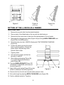
SETTING UP THE L-250/350 AS A LABELER
1. Remove top exit roller (media pressure roller) by pulling it out of the plastic
spring-loaded brackets.
Figure 3
2. Place a stack of fan-folded labels on the label tray with labels facing up.
3. Peel off labels from the first nine inches of the label stack.
4. Disengage the label advance rollers by turning LABEL PRESSURE knob [Figure 3A]
to OFF position.
5. Thread labels into the L-250/350 following the LABEL THREADING DIAGRAM
[Figure 5].
6. Loosen label guides [Figure 3B] and adjust position of labels by moving the whole
stack to desired location.
7. Tighten label guides.
8. Pull the end of the label stack until the first label starts to peel off.
9. Make sure the label peels off straight and is parallel with the peeling edge [Figure 3C]
and [Figure 5].
10. Turn LABEL PRESSURE knob [Figure 3A] to ON position.
11. Turn the LABEL ADVANCE knob [Figure 3D] COUNTER-CLOCKWISE until the
leading edge of next label is visible.
12. Reinstall the media pressure roller.
13. Position tab/label switch to L position.
14. Adjust MEDIA THICKNESS knob [Figure 3E] to desired setting.
-4-
Figure 4
Figure 5
Figure 5a
Label/Stamp
Tabs
SETTING UP THE L-250/350 AS A TABBER
FAN-FOLDED TABS
1. Remove the top exit roller from the plastic brackets.
2. Place a stack of fan-folded tabs on the tray with the tabs facing up.
3. Remove the first nine inches of tabs from the backing paper to form a leader.
4. Disengage the label advance rollers [Figure 4A] by turning LABEL PRESSURE knob
[Figure 3A] to the OFF position.
5. Thread the tabs into the L-250/350 following the TAB THREADING DIAGRAM
[Figure 5a].
6. Position the tabs by moving the entire
stack to desired location. Loosen the
guides [Figure 3B] and align them
with the stack of tabs.
7. Tighten guides.
8. Pull the backing paper until the first
tab starts to peel off.
9. Slide folding guide spring [Figure 6A]
to a position directly below sensor
guide [Figure 6B].
10. Turn the LABEL ADVANCE [Figure 3D]
COUNTER-CLOCKWISE until a tab is in
the slot [Figure 6C].
Figure 5
Figure 5a
Labels/Stamps
Tabs Only
11. Align folding guide spring [Figure 6A] so that
the tab is centered in the slot {Figure 6C].
Figure 6
12. Remove tab from the slot and reinstall media pressure roller.
13. Set media height by adjusting MEDIA THICKNESS knob [Figure 3E].
14. Position tab/label switch to T position.
-5-
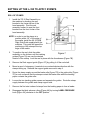
SETTING UP THE L-350 TO APPLY STAMPS
ROLL OF STAMPS
1.
Install the TR-10 Reel Assembly on
the machine by hooking the rear
bracket to the center tie bar of the
head assembly. Pivot the reel
assembly forward to seat the front
bracket over the front tie bar of the
head assembly.
NOTE: In order to run the stamp at a
position within 1/4” of the edge of
the media, install the 90-103-02B
Right Side Guide supplied with the
machine. This guide will permit the
positioning of the stamp at the top
edge of the media.
2.
To position the reel, slide the whole
Figure 7
assembly on the tie bars until the tracking
guides [Figure 7A] are over the desired
location of the stamp. Lock the reel in place with the thumbscrew [Figure 7B].
3.
Remove the Reel support guide [Figure 7C] by pulling it off the reel shaft.
4.
Mount a spool of stamps so it unwinds in a counterclockwise direction with the
stamps facing up. Reinstall the support guide removed in step 4.
5.
Route the stamp supply around the brake roller [figure 7D] to the guide roller [Figure
7E] in such a manner that the stamps contact the brake roller while the backing
paper contacts the guide roller.
6.
Loosen the two tracking guide screws and separate the guides. Route the stamp
supply between the guides and clamp support rails.
7.
Remove the first nine inches of stamps from the backing paper to form a leader.
8.
Disengage the label advance rollers [Figure 4A] by turning LABEL PRESSURE
knob [Figure 3A] clockwise to the OFF position.
-6-
9.
Thread the stamps into the L-350 following the LABEL THREADING DIAGRAM
[Figure 5].
10.
Position the stamps by moving the entire stack to desired location. Lock the reel in
place with the thumbscrew [Figure 7B].
11.
Tighten guides.
12.
Pull the backing paper until the first stamp starts to peel off. Then set the label
sensor adjustment.
13.
Slide the folding guide spring, so that the
media sensor [8A] is positioned to the left
of the sensor guide [8B].
NOTE: The folding guide spring contains
the media sensor and must be positioned
per the illustration. Do not position the
media sensor directly below the backing
paper or it may stay interrupted, creating
an error condition.
B
14.
Set media height by adjusting MEDIA
THICKNESS knob [Figure 3E].
15.
Position tab/label switch to L position.
16.
Run a test sample to check position. Adjust the position using the LABEL
POSITION adjustment on the control panel.
Figure 8
-7-
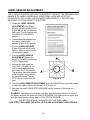
LABEL SENSOR ADJUSTMENT
THE L-250/350 HAS BEEN FACTORY CALIBRATED TO DETECT THE PRESENCE AND
ABSENCE OF LABELS UNDER MOST CONDITIONS. HOWEVER, WITH THE
VARIATION OF BOTH LABEL AND BACKING PAPER DENSITY, IT MAY BECOME
NECESSARY TO FINE-ADJUST THE SYSTEM.
1. Locate the LABEL SENSOR
ADJUSTMENT knob [Figure
9A] and red light emitting diode
[Figure 9B] on the non-operator
side cover. Turn the switch fully
COUNTER-CLOCKWISE to
position 1.
2. Thread labels/tabs/stamps into
the labeler following the
diagram [Figure 5 or Figure 8].
3. Turn the LABEL ADVANCE
[Figure 3D] knob until the first
label (or tab) just starts to peel
off the backing paper.
4. Turn the LABEL SENSOR
ADJUSTMENT [Figure 9A]
knob CLOCKWISE until the red
L.E.D. is illuminated.
5. Release the label pressure
roller (turn it off) and pull the
label material approximately
two inches out of the machine.
This ensures the backing paper
is the only part, which is seen
by the label sensor. The red
L.E.D. will not come on at this
time.
Figure 9
6. Turn the LABEL SENSOR ADJUSTMENT knob CLOCKWISE and count the number
of clicks the switch makes until the red L.E.D. comes on.
7. Now turn the switch COUNTERCLOCKWISE half the number of clicks that you
counted.
EXAMPLE: the light comes on at the sixth click. Now remove the tab from in front of
the sensor and turn the switch six clicks CLOCKWISE. The light comes on again. Now
turn the switch three positions back or COUNTERCLOCKWISE.
THE SYSTEM IS NOW CALIBRATED TO THIS TYPE LABEL.
THIS STEP CONCLUDES THE INITIAL SETUP AND ADJUSTMENT PROCEDURES.
-8-
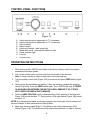
CONTROL PANEL FUNCTIONS
Figure 10
A.
B.
C.
D.
E.
F.
G.
H.
I.
Label vertical position adjustment in 1/2" increments
Label vertical position adjustment in 1/32" increments
Zip-sort switch
Speed control
Label on/off switch - label ready light
Media feed on/off - reset switch media out light
Power indicator light
Counter
Counter reset
OPERATING INSTRUCTIONS
1. After setting up the L-250/350 (see Setup Instructions), place a stack of envelopes
between the envelope guides.
2. Pull out the receiving tray one-inch more than the length of the envelope.
Note: If using a conveyor; slide out and remove the receiving tray.
3. Turn the speed control knob [Figure 10D] to minimum and press FEED switch [figure
10F]
4. Observe how the envelopes are feeding. If they are skewing, readjust the stripping
device [Figute2D]. Press the FEED switch again. The L-250/350 will stop. IF THERE
IS AN ENVELOPE BETWEEN THE EXIT ROLLERS, REMOVE IT SO IT DOES
NOT COVER THE MEDIA PHOTOSENSOR.
5. Set the LABEL POSITION switch to desired setting. Each position of the left switch
Figure 10A] moves the label 1/2". Each position of the right switch [Figure 10B] moves
the label 1/32".
NOTE: Any attempt place labels at a distance greater than the length of the envelope will
cause the labeler to feed media without affixing labels.
6. Make sure there is a label [Figure 11A] visible by the peeling mechanism of the
labeler [Figure 11B]. The photosensor that senses the presence of a label is located
-9-
at the edge of the peeling mechanism. If the sensor does not see the label, any
attempt to run the labeler will result in failure to feed the media. A flashing light
indicates labeler is out of labels.
7. Depressing the LABEL switch [Figure 10E] will activate label-affixing circuitry in the
labeler. The yellow indicator light should be on. Depressing the FEED switch [Figure
10F] will activate feeding mechanism and labeling process.
8. Adjust speed to desired setting by turning the speed control knob [Figure 10D]. Add
envelopes to the labeler as needed. To stop the labeler, depress the FEED switch.
9. DO NOT FORGET TO REMOVE ENVELOPE FROM BETWEEN EXIT ROLLERS
PRIOR TO ACTIVATING LABELER.
10. If the labeler runs out of envelopes, it will automatically stop after a few seconds. The
green light in the FEED switch will start flashing indicating an OUT-OF-ENVELOPES
condition. Depress FEED switch to reset labeler. Load envelops between the guides
and depress switch to start the labeling process.
11. If there are no more labels, or, if two or more consecutive labels are missing, the
labeler will stop and the yellow LABEL OUT indicator light will flash.
12. The counter (H. Fig. 8) will advance one count with every label placed on an envelope.
It will only count when LABEL ON switch is activated. Maximum count is 99,999. To
reset the counter to 0, depress the COUNTER RESET switch (1, Fig. 8).
WARNING
NEVER LEAVE THE L-250/350 WITH POWER ON FOR
A PROLONGED PERIOD. DAMAGE TO INTERNAL
COMPONENTS MAY RESULT!
ZIP-SORT
With the ZIP-SORT switch ON [Figure 10C], the machine will stop every time a missing
label is detected. To activate this feature, manually remove leader label from each zip
code or carrier route prior to loading labels onto the labeler and slide the ZIP-SORT switch
to the ON position. Operate the labeler in the usual manner.
When a missing label is detected, the labeler will stop and the LABEL OUT indicator light
will flash. Depress the FEED switch to reset the machine, and, using the LABEL
ADVANCE knob, bring the next label to the peeling mechanism. Separate the labeled
pieces. Depress the FEED switch again to resume labeling.
-10-
USING AN OPTIONAL CONVEYOR WITH THE L-250/350
Warning: Before connecting a conveyor to the power outlet on the L-250/350, please be
sure it meets the following electrical specifications: 115 VAC and a maximum current
draw of 1 amp or less.
1. Slide out and remove the receiving tray. Position the conveyor against the labeler.
2. Plug the power cord from the conveyor into the conveyor receptacle on the rear of
the L-250/350. Turn on the conveyor’s power switch. The conveyor will now be
stopped/started by the tabber/labeler.
3. Depress the FEED switch on the labeler. The conveyor will start working. Depress
the FEED switch again and the conveyor will stop.
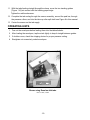
INSTALLING THE OPTIONAL TR-10 REEL ASSEMBLY
The reel assembly will allow the machine to utilize tabs supplied on a roll instead of the
standard fan-folded tabs. This assembly will also allow the L-350 to utilize stamps
supplied on a roll. The major benefits of this are fewer threading cycles as a roll can hold
as many as 10,000 tabs.
1. Remove the standard label feed tray.
2. Mount the reel assembly to the machine by hooking the rear bracket to the center tie
bar of the head assembly.
3. Pivot the reel assembly forward to seat
the front bracket over the front tie bar
of the head assembly.
4. To position the reel, slide the whole
assembly on the tie bars until the
tracking guides [Figure 11A] are over
the desired tabbing area.
5. Lock the reel in place with the
thumbscrew [Figure 11B].
6. Remove the reel support guide [Figure
11C] by pulling it off the reel shaft.
7. Mount a spool of tabs so it unwinds in a
COUNTER-CLOCKWISE direction with
tabs facing up. Reinstall the support
guide removed in step 6.
8. Route the tab supply around the brake
roller [Figure 11D] to the guide roller
[Figure 11A] in such a manner that the
tabs contact the brake roller while the
backing paper contacts the guide roller.
Figure 11
9. Loosen the two tracking guide screws and separate the guides.
10. Route the tab supply between the guides and clamp support rails.
-11-
11. With the tabs feeding straight through the clamp, move the two tracking guides
[Figure 11A] into contact with the backing paper edge.
Tighten the red thumbscrews.
12. Complete the tab routing through the sensor assembly, around the peel bar, through
the pressure rollers, and into the take-up roller split shaft see Figure 8 in this manual.
13. Center the sensor on the tab supply.
OPERATING HINTS
1. Fan out the envelopes before loading them into the tabber/labeler.
2. After loading the envelopes, tap the stack lightly to keep it straight between guides.
3. If doubles occur, check the stripping device for proper pressure setting.
4. Straighten out excessively curled envelopes.
Shown using Rena fan-fold tabs.
Part # 1300T, 1500T
-12-
Copyright © 2008 All rights reserved