1
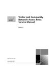
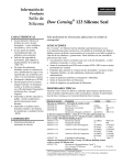
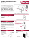
Window Installation
StormPlust and Structural Installations
These instructions are applicable for the following Structural installations:
Clad Ultimate Double Hung Magnum
Wood Ultimate Double Hung Magnum
These instructions are applicable for the following StormPlus products:
Clad Ultimate Casement1
Clad Ultimate Double Hung (CUDH)2
Clad Direct Glaze Polygon/Round Top
Clad Ultimate Double Hung Magnum
Wood Ultimate Casememt1
Wood Ultimate Double Hung (WUDH)2
Wood Direct Glaze Polygon/Round Top
Wood Ultimate Double Hung Magnum
NOTE: Certified IZ2 and IZ3 Ultimate Casement, Ultimate Double Hung, and Direct Glaze Polygon/
Round Top units must be installed using jamb screws or structural brackets. Certified IZ3 Ultimate
Double Hung Magnum units must be installed using the jamb screw method only.
ABSTRACT
These instructions advise the window installer/carpenter/contractor on the recommended way to install Marvin
windows where structural installation is necessary, including those rated for use in Impact Zones 2 and 3. Exact
installation methods for Impact Zone 4 windows are NOT included. Instead, refer to the Notice of Acceptance (see
details inside).
In addition to steps for installing your window, included within are: Rough opening (RO) preparation for recessed
masonry applications; RO prep and sealing details for standard wood frame construction; detailed fastening
methods and more.
The procedures within these instructions are consistent with those used in testing to achieve the advertised DP
rating. Contact your local Marvin dealer if your construction scenario differs from those detailed within.
Regional standard practices, environmental conditions and codes may vary and supersede the
procedures contained within. The responsibility for compliance is yours: the installer, inspector, and
owner(s). See the Technical Installation Specifications inside for more details.
1Includes
2Includes
Awning, Operator, Picture 1,, Stationary 3/4,, Round Top Operator, and Round Top Stationary.
Picture, Transom, Round Tops and Polygon
19970019
2013−03−01
Table of Contents
Page
Technical Installation Specifications . . . . . . . . . . . . . . . . . . . . . . . . . . . . . . . . . . . . . . . . . . . . . . . . . . . . . . . . . . . 2
Before You Begin . . . . . . . . . . . . . . . . . . . . . . . . . . . . . . . . . . . . . . . . . . . . . . . . . . . . . . . . . . . . . . . . . . . . . . . . . . . . . 3
Installer and Builder Information, Homeowner Information, and Aftermarket Products
Step One − Rough Opening and Framing Requirements . . . . . . . . . . . . . . . . . . . . . . . . . . . . . . . . . . . . . . . . . 4
Concrete Block with Plywood Buck, Concrete Block with 2, Buck or Standard Wood Framing
Step Two − Unit Preparation . . . . . . . . . . . . . . . . . . . . . . . . . . . . . . . . . . . . . . . . . . . . . . . . . . . . . . . . . . . . . . . . . . . 6
Packaging, Shipping Blocks, Jamb Extension, Nailing Fin and Wood Brick Mould Casing
Step Three − Installing the Window . . . . . . . . . . . . . . . . . . . . . . . . . . . . . . . . . . . . . . . . . . . . . . . . . . . . . . . . . . . . 7
Shimming, Plumbing and Squaring
Fastening Methods and Jamb/Sill Screw Chart . . . . . . . . . . . . . . . . . . . . . . . . . . . . . . . . . . . . . . . . . . . . . . . . . 8
Wood Screws/Concrete Anchors and Structural Brackets
Special Fastening Systems . . . . . . . . . . . . . . . . . . . . . . . . . . . . . . . . . . . . . . . . . . . . . . . . . . . . . . . . . . . . . . . . . . 10
StormPlus Ultimate Double Hung IZ3 Storm Brackets
Step Four − Final Installation Procedures . . . . . . . . . . . . . . . . . . . . . . . . . . . . . . . . . . . . . . . . . . . . . . . . . . . . . 11
Standard Frame Construction and Recessed Masonry Applications.
Continuous Air Barrier Systems . . . . . . . . . . . . . . . . . . . . . . . . . . . . . . . . . . . . . . . . . . . . . . . . . . . . . . . . . . . . . . 12
Installation, Integration, and window installation tips for house wrap.
Removing Interior Stops, Liners, and Fillers . . . . . . . . . . . . . . . . . . . . . . . . . . . . . . . . . . . . . . . . . . . . . . . . . . . 14
Removing Casement interior stops, Removing Ultimate Double Hung jamb carriers
Removing Sash . . . . . . . . . . . . . . . . . . . . . . . . . . . . . . . . . . . . . . . . . . . . . . . . . . . . . . . . . . . . . . . . . . . . . . . . . . . . . 15
Ultimate Double Hung and Ultimate Casement Operators
StormPlus IZ4 Notice of Acceptance Information . . . . . . . . . . . . . . . . . . . . . . . . . . . . . . . . . . . . . . . . . . . . . . 16
Warranty
Painting and Staining Information
19970019
2013−03−01
1
Window Installation
StormPlus and Structural Installations
Technical Installation Specifications
The following details are specified for proper installation and for the unit to meet the advertised design pressure
(DP) rating.
S Rough Opening Width: 1/4,−1, (6−25) wider than
window/door frame outside measurement.
S Properly flash and/or seal all windows at the exterior
perimeter.
S Sealants used for installation must be Grade NS Class 25
per ASTM C920 and compatible with the building exterior,
window exterior surface, and flashing/water management
materials.
S Flashing materials must comply with ASTM E2112−01,
section 5.13 and be compatible with all materials used in
installation including panning systems, air barriers and
building papers, sheathing, and the window unit.
Flashing material must not contain asphalt and must
be compatible with flexible PVC (vinyl) when used in
conjunction with nailing fin.
S Optional foams used for installation must be low expansion
only. Foam and foam application must comply with ASTM
E2112−01, SEC 5.9.2.
S Rough Opening Height: 1/4,−1/2, (6−13) higher than
window/door frame outside measurement.
S Masonry Opening Width: 1/4,−1/2, (6−13) wider than
window/door frame outside measurement.
S Masonry Opening Height: 1/8,−1/4, (3−6) higher than
window/door frame outside measurement.
Architectural Detail Manual Specifications:
S Rough Opening:Width 1, (25); Height 1/2, (13).
S Masonry Opening:Width 1/2, (13); Height 1/4, (6).
S If using less than a nominal 2, x buck in masonry
openings; the rough opening must be no more than
1/2,(13) wider and 1/4,(6) taller than the outside
measurement of the frame. Installation methods are
limited to Jamb Screw method using 3/16, concrete
screws.
S Shims are required between the window frame and framing
members at all locking points and at every point of
attachment (excluding nailing fin and brick mould casing)
as well as at all points detailed within these instructions.
S For units with flat casing install with installation brackets,
structural masonry brackets, or jamb screws.
S Marvin recommends the use of sloped sills on all concrete
openings (either pre−cast or poured).
S Do not use chemically treated products for shim material.
S Regarding recessed masonry openings: the window
frame must not come in direct contact with
masonry/concrete/concrete block. Construct framing
from treated lumber or plywood and fasten to the masonry
opening jambs, header, and sill. This framing must be
designed (and anchored to the opening) properly to
withstand certified and advertised DP ratings for your
particular unit.
S Fasteners penetrating chemically treated lumber must be
a minimum of 0.90 oz/ft2 zinc hot dipped galvanized or
stainless steel type 304 or 316.
S Clad window frames must not come into direct contact with
chemically treated wood products.
S For installations in typical wood frame construction (with
sheathing and building paper or air barrier material)
where a continuous air barrier system is used, refer to
ASTM E2112−01 or reference the “Continuous Air
Barrier Systems” section for details on preparing the
rough opening and sealing the installation.
S For installations in concrete block, or masonry
construction, etc., follow local codes for sealing and water
management details.
Be aware that the use of rigid sill pans and
other barriers will decrease the rough
opening height clearance. Adjust opening
dimensions accordingly.
WARNING: Drilling, sawing, sanding or
machining wood products generates wood
dust, a substance known to the State of
California to cause cancer. Avoid inhaling
wood dust or use a dust mask or other
safeguards for personal protection.
California Health and Safety Code Section
25249.6.
19970019
2013−03−01
2
Window Installation
StormPlus and Structural Installations
Before You Begin
Installer and Builder Information
S Read these instructions thoroughly BEFORE beginning to
install your Marvin window product.
S It is the responsibility of the builder, installer and
subcontractors to protect the interior and exterior of
windows or doors from excessive contact with harsh
chemical washes, construction material contamination and
moisture. Damage to glazing, hardware, weatherstrip and
cladding/wood can occur. Protect with painters tape and/or
protective sheathing as required. Follow all guidelines
regarding material use, preparation, personal safety and
disposal.
S Always provide a copy of these instructions for the current
or future building owner.
S Plan sizing of rough opening and clearance from exterior
finishing systems to allow for normal materials shrinkage or
shifting (e.g. wood structure with brick veneer, allow
adequate clearance at sill). Failure to do so can void the
Marvin warranty coverage.
S Refer to the enclosed painting and staining instructions on
the last page for exterior and interior finish instructions.
S Refer to the Technical Installation Specifications section
for technical specifications regarding the installation of this
product. These installation requirements as well as the
details in this section must be followed to achieve the
advertised design pressure (DP) rating of this product.
S Contact your Marvin supplier if you have any questions
regarding product and materials used in manufacturing or
questions on replacement parts.
Aftermarket Products
Alterations to Marvin products including window films, insulating or reflective interior window treatments or additional glazings
can cause excessive heat buildup and/or condensation. They may lead to premature failures not covered under warranty by
Marvin Windows and Doors.
Before purchasing or applying any product that may affect the installation or performance of Marvin windows contact the
manufacturer of aftermarket product/glazings that are not supplied by Marvin and request written product use, associated
warranties and damage coverage. Provide this information and warranties to the end user and/or building owner for future
reference.
Hazard Notations
Please familiarize yourself with the following hazard notations used throughout this instruction.
Caution
Warning
Seek Assistance
Tips/Hints
Impact Product
Mistakes or misuse
could cause damage
to the window or
result in faulty
installation and unit
performance.
Mistakes or misuse
could result in
personal injury and/or
severe damage to
unit, equipment,
and/or structure.
Help from another
individual is necessary
to perform this task
safely and correctly.
Information on
alternative
procedures,
definitions, helpful
hints.
Steps related to
Impact rated
products only.
Standard Parts Shipped
You Will Need to Supply
Units are sent with hardware; clad units are sent with
four (4) nailing fin corner gaskets. Follow installation
instructions included with part if applicable. UDHM
units are sent with a fastening package and supplemental installation instructions.
Safety glasses
Hearing protection
Level
Square
Hammer
Wood shims
Insulation
Tape measure
Sill pan flashing
Perimeter sealant1
Backing material (foam backing rod)
Low expansion foam insulation2
Appropriate fastener (see Jamb/Sill Screw Chart)
Construction adhesive3
NOTE: Depending on the installation method, other
material may be needed to properly prepare and seal
the installation such as self sealing adhesive membrane, building paper, and seam seal tape, etc.
NOTE: Numbers listed in parentheses ( ) are metric
equivalents in millimeters rounded to the nearest whole
number.
WARNING: Always practice safety!
Wear the appropriate eye, ear and hand
protection, especially when working
with power tools.
1Sealant
must be Grade NS Class 25 per ASTM C920 and compatible with building exterior and window surface.
use low expansion foam insulation only. Foam and foam application must comply with ASTM E2112, section 5.9.2.
3APA rated AFG−01 spec
2Optional,
19970019
2013−03−01
3
Window Installation
StormPlus and Structural Installations
Step 1:
Rough Opening and Framing Requirements
This section gives requirements for framing and rough opening clearances. Masonry or concrete openings must be
lined with a treated wood product (wood buck). You must fasten the buck to the masonry opening in a fashion that
will withstand conditions which would be encountered under the certified and advertised DP ratings for this window.
The structural integrity of this installation is only as good as the bond between the wood buck and the masonry
opening. For more details, contact your Marvin representative.
NOTE: Wood buck material thickness may vary. Illustrations show a 1/2, plywood and 2 x 4 buck. Installations
using material less than 2, nominal material must use the jamb screw method of attachment and use 3/16, concrete
anchors.
Treated
2 x 4 buck
Construction
adhesive
(a)
Adhesive
flashing
Masonry
anchor
1/2, treated
plywood
(c)
(b)
Figure 1: Preparing openings for concrete block openings.
1. On concrete block, masonry, or similar situations, line
the sides, head jamb, and sill with treated lumber.
Attach the lumber to the masonry opening with
construction adhesive and masonry anchors which
should penetrate the masonry opening by at least
1,−1 1/2, (25−38). See figure1a and 1b.
NOTE: If your installation requires screwing through
the sill for structural purposes, place a bead of sealant
where the screws will penetrate the rigid sill panning.
4. The window frame must not come in contact with
treated lumber. If you will not be using rigid panning
or shimming at the sill, apply a barrier such as a self
sealing adhesive flashing to the rough opening sill.
See figure 1 c.
2. For standard wood frame construction, prepare the
opening following local codes, ASTM E2112−1, or follow the steps in the “Continuous Air Barrier
Systems” section.
3. If rigid panning is used, place a bead of silicone or
construction adhesive over any fasteners used to
hold the panning to the sill.
19970019
2013−03−01
4
Window Installation
StormPlus and Structural Installations
Step 1:
Rough Opening and Framing Requirements (cont.)
1/2,
1/4,
1/4,
1/2,
Rough Opening
Masonry Opening
Figure 2: Preparing openings for concrete block openings.
5. Rough openings1 (RO) should be 1, (25) wider than
the outside measurement of the frame and 1/2, (13)
higher. Masonry openings (MO) should be 1/2, (13)
wider than the outside measurement of the frame or
casing and 1/4, (6) higher than the outside measurement of the frame or casing. When framing rough
opening, care should be taken to ensure the sill plate
is level and the opening is square, straight and plumb.
See figure 2.
ATTENTION: Be aware that use of rigid sill pans and
other barriers will decrease the rough opening height
clearance. Adjust opening dimensions accordingly.
CAUTION! If the previous conditions are
not met, the installer must take corrective
actions to alter the opening(s) before
proceeding. It is also essential that the sheathing
behind the wall be a solid surface to ensure that
the unit can be secured firmly to the wall.
NOTE: On standard wood frame construction with
brick veneer, make sure there is at least 1/2, (13)
between bottom of window sill (or eventual
placement of the window) and the top row of brick
to avoid “brick bind”.
1Rough
opening gap must be no more than 1/4, for products certified for use in IZ4 regions.
19970019
5
2013−03−01
Window Installation
StormPlus and Structural Installations
Step 2:
Unit Preparation
1. Remove the protective packaging from the unit
and dispose/recycle properly. Inspect unit for
any hidden damage and report immediately to
your Marvin representative. Provide the customer service number etched on one of the top
corners of the glass. See figure 3.
Customer service number
2. Remove any shipping clips unless noted otherwise.
NOTE: Do not remove the vinyl shipping blocks
or shipping tube assembly on Ultimate Double
Hungs until installation is complete (unless
installing with jamb screws).
3. If used on clad units, position the factory applied
nailing fin/drip cap in the upright position. See
figure 4.
4. On wood units with brick mould casing, apply
sealant at the casing to frame joint along the
jambs and head jamb, at the sill horn to casing
joint, and at the miter corners of the casing. See
figure 5. Tool the bead to ensure proper adhesion to both surfaces.
Figure 3:
5. If you are installing a window with structural
brackets, fasten to the window now. Follow the
fastener spacing in the “Jamb/Sill Screw
Chart”. Follow the instructions provided with
the brackets for details on how to fasten to unit.
Ultimate Double Hung Magnum units are sent
with supplemental instructions which detail how
to remove the sash and jamb fillers.
6. If you will be fastening with screws through the
jambs, head jambs, and sill, remove your sash
and covers or liners at this time. Refer to the
section, “Removing Interior Stops, Liners,
and Fillers” and “Removing Sash” for details.
Figure 4: Extend nailing fin.
7. Install jamb extension before installing the window in the rough or masonry opening. Follow instructions provided with the jamb extension.
Figure 5: Apply back−caulking to BMC.
19970019
2013−03−01
6
Window Installation
StormPlus and Structural Installations
Step 3:
Installing the Window
The following steps provide details for structural fastening of the window to the opening. When installing windows
with nailing fin or wood brick mould casing, it may be desirable to first attach the window using these fastening
methods in conjunction with steps 1−5. Then complete the installation by fastening with structural brackets or
screws. Always follow fastener spacing outlined in the “Jamb/Sill Screw Chart” section. On applicable construction
using a continuous air barrier system, prepare the opening before installing the window. Refer to the “Continuous
Air Barrier Systems” section for details.
Measure
diagonally
for square
(b)
(a)
(c)
Figure 6: Plumb and square unit. (Illustration shows both structural bracket and jamb screw installation.)
5. Fasten and shim at the top corners to square the unit
in the opening. Take diagonal measurements of the
window. When equal, the window is square in the
opening. Adjust the shims and fasteners until the unit
is square in the opening. See figure 6b.
Seek Assistance: Some large windows
and/or assemblies are very heavy. Avoid
injury by getting help to lift and position the
window into the rough opening.
CAUTION: Proper shimming is extremely
important. Under−shimming or over−
shimming will result in bowed jambs and
or head jamb. Both conditions can contribute to
improper window operation and performance.
1. If rigid sill pan is not used, pan sill with alternate methods or shim under window sill to ensure it does not
come in direct contact with treated lumber.
2. On some larger units such as the Ultimate Double
Hung Magnum, it may be necessary to remove the
sash prior to installation. See the sash removal section for details.
Installation Tip: On operating units, one
method to ensure that the unit is installed
square is to check the reveal (gap) between the
operating sash and the frame. An even reveal around
the entire sash generally indicates a correctly
installed unit and will ensure smooth operation.
3. Center the window in the opening. Level at the sill
and plumb the frame (interior/exterior) to desired
depth.
4. Fasten and shim the jambs at the bottom with the
appropriate fastener (follow instructions in the
“Fastening Methods” section). See figure 6a.
6. Complete shimming and fastening at locations and
spacing specified in the “Jamb/Sill Screw Chart”.
See figure 6c.
NOTE: Some units such as the Ultimate Double Hung
Magnum and IZ3 Ultimate Double Hung, feature unique
fastening systems. For these windows refer to the “Special Fastening Systems” section for details.
7. Recheck the diagonals one more time to make sure
the unit is square in the opening. Adjust fasteners as
necessary to bring to square.
8. Once the unit is installed square and plumb, operate
the sash (on operable units) to make sure it is operating properly. If not, you may have to make some additional adjustments to the shims and fasteners.
9. If removed, replace your stops, covers, and liners.
19970019
2013−03−01
7
Window Installation
StormPlus and Structural Installations
Fastening Methods and Jamb/Sill Screw Chart
Although structural installations may involve fastening with wood brick mould casing or nailing fin, there are two ways
to fasten your jambs to the opening for structural purposes:
1. #8 Wood screws (or 3/16, concrete anchors), 6, (152) from all corners and
15, (381) on center around the perimeter.
or
2. Structural brackets, 6, (152) from all corners and 15, (381) on center around the perimeter.
Refer to the “Jamb/Sill Screw Chart” for proper fastening requirements for your particular product. Illustrations
show a concrete block opening but apply to typical wood frame construction as well.
NOTE: All mulled units require fastening with two screws or brackets on each side of the mull joint no more than
6, (152) from mull joint.
NOTE: Single UDH products do not require fastening at the sill. Multiple wide UDH assemblies require anchoring
at the sill mullion. UDHM IZ3 units must be installed with jamb screws, fastening at the sill is not required.
Structural Brackets
Jamb/Sill Screw Chart
1. Wrap brackets around the framing/buck/opening,
fasten with two #8 x 1 5/8, screws. Angle the screws
approximately 15 degrees away from the window.
Always shim above or behind installation brackets.
Shim
1/4,
5/32, holes
Screws
Jamb Screw
Length
Sill Screw
Length
Clad Ultimate
Casement Family
and Direct Glaze
3, (76)
2 1/2, (64)
Wood Ultimate
Casement Family
and Direct Glaze
3, (76)
3 1/2, (89)
Ultimate Double
Hung Family
2 1/2, (64)
N/A
Ultimate Double
Hung Magnum
Family*
Supplied
with unit
N/A
Product
* Use predrilled holes in frame members.
Jamb/Sill Screws
1. Space fasteners along jambs and head jambs no
more than 6, (152) from each corner and 15, (381)
on center. Follow same spacing for sills when applicable.
NOTE: Structural brackets are allowable replacements
for screws if fastening at the sill is necessary.
Figure 7
2. After removing covers or liners, fasten units to the
framing with #8 wood screws or 3/16, concrete anchors1. Adjust length of fastener so that it penetrates
no less than 1 1/4, (32) into framing/opening. When
fastening through the sill, always pre−drill and fill
hole with sealant before driving the screw. Always
place a shim behind or above the screw location on
jambs and head jambs.
NOTE: When using masonry anchors, be sure to follow
manufacturer’s guidelines for proper installation. Some
types require pre−drilling.
1Use
concrete anchors when wood buck material is less than 2, nominal thickness.
19970019
8
2013−03−01
Window Installation
StormPlus and Structural Installations
Fastening Methods (cont.)
3. On Ultimate Casement units, position the screw so
that it misses any operating hardware (if applicable).
With typical installations, you should be able to locate
the screw in the center groove in the frame and just
to the exterior of the kerf that holds the head jamb
stop. See figure 8.
4. On Ultimate Double Hung units, locate the screw in
the jamb carrier kerf (jambs) and in the kerf used to
hold the parting stop (head jamb). Make sure to
countersink the screw so that it doesn’t interfere with
installation of the jamb liner and/or parting stop. See
figure 9.
Fastener
Fastener
Figure 9: Exterior View, fastening through UDH frames.
5. On IZ3 Ultimate Double Hung units, fasten through
the “Storm Brackets” on the jambs with two
#8 x 2 1/2, (64) wood screws through the top bracket
and one screw through the bottom bracket. See the
“Special Fastening Systems” section for more details.
Figure 8: Exterior view, fastening through Ultimate Casement
frames.
19970019
2013−03−01
9
Window Installation
StormPlus and Structural Installations
Special Fastening Systems
StormPlus Ultimate Double Hung IZ3 Storm Brackets
(a)
(d)
(e)
(b)
(c)
(f)
Figure 10: Fastening UDH Storm Brackets.
1. Ultimate Double Hung IZ3 units have two storm
brackets attached to each jamb. If you are using
the jamb screw method for installation you will notice these when you remove the clad and wood fillers. If you are using the masonry bracket method,
you must first remove the check rail dust block and
pull out the bottom part of the top jamb weather
strip as well as remove the bottom sash stay. See
figures 10a and 10b.
2. Push the clad jamb filler up as far as it will go to reveal the predrilled hole in the jamb carrier. Fasten
the jambs through the storm bracket by driving one
of the #8 x 2 1/2, screws through the pre−drilled
hole in the jamb. See figure 10c.
5. Extend storm brackets during inclement
weather by inserting
a stick pin, nail, or
pen through the hole
in the bracket. Then
slide the bracket
away from the window frame as shown
in figure 11.
Figure 11: Using storm brackets
3. Press the top jamb weatherstrip back into place.
Slide the bottom jamb filler down as far as it will go.
Fasten the jamb through the storm bracket by driving two of the #8 x 2 1/2, screws through the pre−
drilled holes in the jamb. See figure 10d.
WARNING: IZ3 storm protection for
CUDH operators requires that storm
brackets be put in the extended position.
If the homeowner will be away from home for any
period of time in which strong winds are possible, it is recommended that the storm brackets
be pulled out to the extended storm ready position before leaving home.
4. Slide the bottom jamb filler back up until it touches
the jamb weatherstrip. Replace the check rail dust
block and the bottom sash stay. See figures 10e
and 10f.
19970019
2013−03−01
10
Window Installation
StormPlus and Structural Installations
Step 4:
Final Installation Procedures
This section does not include details on sealing installations that incorporate a continuous air barrier system such
as house wrap or building paper in standard wood frame construction. For flashing details in this application refer
to the section, “Continuous Air Barrier Systems − Flashing the Installation”.
Sealant
Backer
rod
Sealant
(a)
(b)
(c)
Figure 12: Sealing recessed masonry openings
1. Place a bead of sealant at the wood buck to masonry
joint. See figure 12a.
3. In some situations such as recessed masonry
openings, you can use frame expander or other
clad accessories to finish the exterior. If this is the
case, apply a bead of sealant between the accessory and the masonry at the head jamb and jamb
sections. Leave the sill portion unsealed to allow
water to escape. See figure 12c.
2. For recessed masonry applications, Marvin recommends sealing at the buck to frame joint with appropriate width backer rod and sealant around the entire perimeter. Finish as applicable local code dictates. See figure 12b.
Low
expansion
foam
Fiberglass
insulation
Figure 13: Insulating the rough opening
4. Apply a 1,−2, (25−51) thick bead of low expansion
foam insulation on the back side of the nailing fin,
brick mould casing or other trim. Do not apply too
much as it is possible to bow the jambs. Now insulate
loosely around the window with fiberglass insulation. See figure 13.
19970019
2013−03−01
5. Interior and mullion trim: Install mullion trim after
interior trim or casing is applied. On Ultimate
Double Hung units, be sure to use nails and staples that are no longer than 3/4, (19). Place fasteners at least 1, (25) from the edge of interior jamb
liner.
11
Window Installation
StormPlus and Structural Installations
Continuous Air Barrier Systems − Preparing the Opening
The method shown below is Method A1 using a TYPE III flash pan. For step by step instructions on how to prepare
an opening using this method, refer to www.marvin.com/ROprep for instructions “Window Rough Opening Prep and
Flashing Method A1−Membrane Drainage System”. Refer to ASTM E2112−07 for other rough opening preparations
that are more appropriate for your situation.
Figure 14: Preparing the opening.
19970019
2013−03−01
12
Window Installation
StormPlus and Structural Installations
Continuous Air Barrier Systems − Flashing the Installation
1. Flash the installation in a weather board
fashion. For step by step instructions,
refer to www.marvin.com/Roprep for
instructions titled “Window Rough
Opening Prep and Flashing Method
A1−Membrane Drainage System”.
Figure 15: Sealing the installation in air barrier applications.
Window Flashing Detail (non−recessed masonry)
Head jamb
flashing
Sealant
Drip cap
Sealant
Seam
seal tape
Jamb
flashing
Window
casing/cladding
Siding/
exterior finish
Figure 16: Flashing windows with casing in typical wood frame construction (non recessed masonry).
NOTE: Figure 16 shows a window with casing but the flashing detail also applies to any clad window product.
For installation in typical wood frame construction or brick veneer (non−recessed masonry openings), figure 16
shows the proper flashing detail in shingle style fashion. Once the exterior finish such as siding or brick veneer is
installed, a bead of sealant should be applied between the finish and the window/window casing along the sides and
approximately 1−2, (25−51) in from the ends at the head jamb (see insert). Use a backer rod when necessary.
19970019
2013−03−01
13
Window Installation
StormPlus and Structural Installations
Removing Interior Stops, Liners and Fillers
Some structural installations that use the “jamb pinning” method require the removal of interior stops before installing
the window. This section details the removal of Ultimate Double Hung (UDH) jamb liners and Ultimate Casement
operator and stationary stops.
Details for UDHM windows can be found in the supplemental instruction sent with the unit.
Removing Ultimate Casement Stops and Covers
(a)
(b)
Figure 17: Removing Ultimate Casement stops and covers.
2. Operator jamb covers are held in place by two barbs:
one on the interior side and one on the exterior side
shared by the frame weather strip. With the sash
opened or removed, first pull the frame weather strip
out of the kerf and set aside for reuse later.
1. Sill and head jamb covers and stops are held in place
with a vinyl barb and can be easily removed by simply
and carefully prying up on the stop with a sharp putty
knife. Be careful not to damage the stop or frame. Occasionally the barb will stay in the frame when you remove the stop. Remove the barb with a pair of pliers
and reinsert into the kerf on the stop/cover. See figure 17a.
NOTE: Stationary jamb stops are removed in the same
fashion. You will need to remove the head jamb and sill
covers first.
3. Remove the sill and head jamb stops.
4. With a sharp putty knife, carefully pry on the interior
side between the stop and the frame. Start at one end
and work your way down until stop loosens. See figure 17b.
Removing UDH Jamb Liners
SHOWN FROM
EXTERIOR
Bottom
filler
channel
Head jamb
parting stop
(a)
(b)
(c)
(d)
(e)
Figure 18
1. Remove the head jamb parting stop with use of a pry
bar. See figure 18a.
3. From the exterior, pry out the jamb hardware assembly using a pry bar by placing it into the bottom filler
channel, hooking it into the notches on the side, and
levering it out. See figure 18c.
2. Use a flat headed tool with a 90 degree elbow to remove the lower fillers from the jamb hardware assembly. This is best done by placing the tool into the space
opened by the removed checkrail pad. Loosen both
corners of the jamb fillers from the notches before trying to remove them, to reduce the possibility of damage
to the fillers. See figure 18b. Be sure to take care when
doing so, as there is a possibility of the fillers breaking.
4. When installation of the unit is complete, seat the
jamb assembly facing towards the exterior first, and
ease the remainder of the assembly into the jamb
pocket. See figures 18d and 18e. Use of a rubber
mallet may be required. If so, take the mallet and,
starting at one end, work your way up the filler, until
fully seated. (Use of a cloth to protect the wood and
keep it clear from direct impact while hammering is
suggested.)
5. Reinstall the checkrail pads and head jamb part stop.
19970019
2013−03−01
14
Window Installation
StormPlus and Structural Installations
Removing Sash
Seek Assistance: Some sash on large windows are very heavy. Avoid injury by getting help to lift and
position the window into the rough opening. For other products not shown here refer to the Marvin
Service Manual or contact your Marvin representative.
Ultimate Double Hung Operator Sash
(a)
(b)
(c)
(d)
Figure 19: Tilting and removing Ultimate Double Hung Sash
1. Raise the bottom sash approximately 4, (102). See
figure 19a.
3. Lift both sides of the sash upward 2,−3, (51−76) (raising the pivot pins out of each clutch). See figure 20c.
2. Pull the tilt lever (nested in the sash lock base) until
it clicks. Hold the lever until latches clear the unit
frame when tilting. Ease top edge of bottom sash out
toward you to a horizontal position. See figure 19b.
4. Rotate the sash until the pivot pins clear the jambs
and remove the bottom sash from the frame. See figure 19d.
5. Tilt and remove the top sash using the same technique used on the bottom sash. (The top sash uses
tilt latches located on both sides of the top rail.)
Ultimate Casement Operator Sash
Hinge
track
Operator track
extension
arm
(a)
Butterfly
clip
(b)
Hinge
arm
(c)
Pivot shoe
(d)
Figure 20: Removing Ultimate Casement Operator Sash
NOTE: Sash with daylight openings of less than 14 1/2,
2. Disconnect the butterfly clip on the short extension
arm from the stud on the sash bracket. See figure 20b.
step 2 for these units.
3. Push the sash open to 90 degrees. With a screwdriver
or similar tool, pry the bottom hinge off from the stud
on the hinge track. Repeat this on the top hinge. See
figure 20c.
(368) will use hinged single arm operator gear. Skip to
1. Crank open sash until the nylon roller on the long extension arm lines up with the arrow on the operator
track. Disconnect the extension arm from the operator track by pushing the roller down through the opening in line with the arrow. See figure 20a.
19970019
2013−03−01
4. Remove the sash by sliding the entire sash on its
hinge pivot shoes toward the hinge track studs. The
shoes will disengage from the track when they hit the
stud. Carefully remove the sash and set aside. See
figure 20d.
15
Window Installation
StormPlus and Structural Installations
IZ4 Notice of Acceptance
Exact instructions for installing windows certified for use in Impact Zone 4 are not included in this publication. The
installer/contractor MUST install the window(s) according to detailed drawings found in the Notice of Acceptance
(NOA) to the Product Control Division of the Miami−Dade County Building Code Compliance Office (BCCO). You
will be able to find the NOA drawings for each certified product on the Miami−Dade County website (exact URLs
listed below), at www.marvin.com, or you may obtain a hard copy by contacting your Marvin representative.
NOA
DESCRIPTION
URL
07−0524.08
Clad Ultimate Casement Polygon/RT
Picture
http://www.miamidade.gov/buildingcode/library/productcontrol/noa/07052408.pdf
07−0524.06
Clad Ultimate Casement Operating RT/
Polygon
http://www.miamidade.gov/buildingcode/library/productcontrol/noa/07052406.pdf
08−0310.11
Clad Awning
http://www.miamidade.gov/buildingcode/library/productcontrol/noa/08031011.pdf
08−0213.08
Clad Ultimate Casement Picture
http://www.miamidade.gov/buildingcode/library/productcontrol/noa/08021308.pdf
08−1014.06
Clad Ultimate Casement Operator
http://www.miamidade.gov/buildingcode/library/productcontrol/noa/08101406.pdf
08−0310.12
Wood Awning
http://www.miamidade.gov/buildingcode/library/productcontrol/noa/08031012.pdf
08−0213.09
Wood Ultimate Casement Picture
http://www.miamidade.gov/buildingcode/library/productcontrol/noa/08021309.pdf
08−1014.07
Wood Ultimate Casement Operator
http://www.miamidade.gov/buildingcode/library/productcontrol/noa/08101407.pdf
07−0924.01
Clad Direct Glaze Polygon/Round Top
http://www.miamidade.gov/buildingcode/library/productcontrol/noa/07092401.pdf
19970019
2013−03−01
16
Window Installation
StormPlus and Structural Installations