1
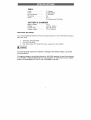
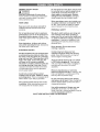
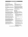
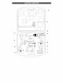
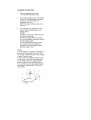
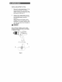
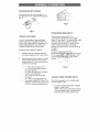
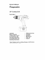
Owner's Manual
3/8" Cordless
Drill
184.10184-1
CAUTION:
Before using this
cordless drill or any of
its accessories,
read
this manual and follow
•
•
•
•
•
Safety Instructions
Assembly
Operation
Maintenance
Parts List
all its Safety Rules and
Operating Instructions.
•
Espanol
Sears, Roebuck
Part No. 18410184-100!
and Co., Hoffman
Rev. O 10/05/03
Estates,
IL 60179 U.S.A.
SECTION
PAGE
Warranty
..........................
2
Product
Specifications
........
3
Power
ToolSafety............. 4 - 6
DrillSafety
.......................
6
Battery
&Charger
Safety....
6- 7
Symbols
..........................
7
SECTION
Know
YourCordless
Drill...
Accessories
...................
Carton
Contents
..............
Assembly
&Operation
......
Maintenance
...................
Parts& Service
................
PAGE
8
9
9- 10
11- 16
16
17- 18
FULL ONE YEAR WARRANTY
If this Cordless Drill fails due to a defect in material or workmanship within
one year of date of purchase, Sears will replace it free of charge.
Return this Cordless Drill to place of purchase for replacement.
This warranty gives you specific legal rights, and you may also have other
rights which may vary from state to state.
Sears, Roebuck and Co., Dept. 817 WA, Hoffman
I_
Estates, IL 60179
WARNINGI
Some
dust
created
by power
sanding,
sawing,
grinding,
drilling
and
other
construction
activities
contains
chemicals
known (to the State of California)
cause cancer, birth defects or other reproductive
harm,
Some examples
of
these chemicals
are:
•
Lead from
lead-based
paints
•
Crystalline
silica
bricks,
cement
•
Arsenic
from
chemically
from
and chromium
and other
treated
masonry
to
products
lumber
Your risk from these exposures
varies, depending
on how often you do this type
of work. To reduce your exposure
to these chemicals,
work in a well ventilated
area and work with approved
safety equipment
such as those dust masks that
are specially
designed
to filter
out microscopic
particles.
DRILL
Chuck
.........................
3/8"
Switch .........................
No Load Speed .............
Reversible
....................
Clutch .........................
Keyless
Variable Speed
0 - 550 RPM
Yes
16 + 1
16 Positions
BATTERY
ADDITIONAL
If you require
place
&
plus Drill Mode
& CHARGER
Battery Voltage ...............
Charger .........................
Charger Input ..................
14.4 V
3-5 Hour, Class 2
120 V AC, 60 Hz
Charger
17V DC, 400mA
Output
...............
BATTERIES
additional
batteries
for this tool, please
contact
us in one of the following
ways
to
your order:
•
Telephone:
•
Fax: (847) 540-0496
•
Mail:
WARNING
(847) 540-0429
MSA Global,
277 Sandy
Point
Lane,
Lake Zurich,
Illinois
60047
]
To avoid electrical
circuit
protection.
hazards,
fire
hazards
or damage
to the battery
charger,
use proper
The battery charger is wired at the factory for 110-120 V operation. It must be connected
to a 110-120 V, 15 A time delayed fuse or circuit breaker. To avoid shock or fire, replace
power cord immediately if it is worn, cut or damaged in any way.
GENERAL
[_L
SAFETY
RULES
Do not abuse
the
to carry the tools
outlet.
Keep cord
WARNING]
Read and understand
all instructions.
Failure to follow all instructions
listed below
may result in electric shock,
serious personal injury.
fire and/or
WORK AREA
Keep your work area clean and well lit.
Cluttered
benches and dark areas invite
accidents.
cord. Never
use the cord
or pull the plug from
away from heat, oil,
an
sharp edges or moving
parts. Replace
damaged
cords
immediately.
Damaged
cords increase the risk of electric shock.
When operating
a power tool outside, use
an outdoor
extension
cord marked "W-A"
or "W". These cords are rated for outdoor
use and reduce the risk of electric shock.
PERSONAL
SAFETY
Do not operate
power tools in explosive
atmospheres,
such as in the presence
of
flammable
liquids,
gasses
or dust. Power
tools create sparks which may ignite the dust
or fumes.
Stay alert, watch what you are doing and
use common
sense when operating
a
power tool. Do not use the tool while tired
or under the influence
of drugs,
alcohol
or
medication.
A moment of inattention while
Keep
operating
personal
bystanders,
children
and visitors
away while operating
the tool.
can cause you to lose control.
ELECTRICAL
supply
Avoid
body
may result
Dress properly.
Do not wear
clothing
or jewelry.
in serious
loose
SAFETY
with
than
the other). This plug will fit in a polarized
plug only one way. If the plug does not fit
fully in the outlet, reverse
the plug. If it
still does not fit, contact
a qualified
electrician
to install
a polarized
outlet.
Do
not change
the plug in any way. Double
insulation eliminates
the need for the three
power
tools
Distractions
Double insulated
tools are equipped
a polarized
plug (one blade is wider
wire grounded
power
injury.
power
can be caught
in moving
parts.
Avoid accidental
starting.
Be sure switch
is OFF before plugging in. Carrying tools
with your finger on the switch or plugging
in
tools that have the switch ON invites
accidents.
cord and grounded
system.
contact
Contain long hair. Keep your hair,
clothing
and gloves
away from moving
parts. Loose clothing, jewelry or long hair
with
grounded
surfaces
such as pipes, radiators,
ranges
and refrigerators.
There is increased
risk of
electric shock if your body is grounded.
Don't expose power tools to rain or wet
conditions.
Water entering the power tool
will increase the risk of electric shock.
Remove
adjusting
keys or wrenches
before turning
the tool ON. A wrench or key
that is left attached to a rotating part of the
tool may result in personal
injury.
Do not overreach.
Keep proper footing
and balance
at all times. Proper footing and
balance enables better control of the tool in
unexpected
situations.
Use safety equipment.
Always wear eye
protection.
Dust mask, non-skid safety
shoes, hard hat or hearing protection
must be
used for appropriate
conditions.
SAVE THESE INSTRUCTIONS
FOR REFERENCE
TOOLUSEANDCARE
SERVICE
Useclampsor otherpracticalwayto
secureandsupportthe workpiece to a
stable platform. Holding the work by hand or
against your body is unstable and may lead
to loss of control.
Do not force
the tool.
Use the correct
tool
for your application.
The correct tool will do
the job better and safer at the rate for which it
is designed.
Do not use the tool
if the switch
does
Tool service
must be performed
only by
qualified
personnel.
Service or
maintenance
performed
by unqualified
personnel
could result in risk of injury.
When servicing
a tool, use only identical
replacement
parts. Follow instructions
in
the Maintenance
section
of this manual.
Use of unauthorized
parts or failure to follow
Maintenance
instructions
may create a risk of
electric shock or injury.
not
turn it ON or OFF. Any tool that cannot be
controlled
with the switch is dangerous
and
must be repaired.
SPECIFIC SAFETY RULES
Disconnect
the plug from the power
source
before making
any adjustments,
For your safety, do not plug in your
charger
or install the battery
in the tool
until you have read and understood
this
Owner's
Manual.
changing
accessories
or storing
the tool.
Such preventive
safety measures
reduce the
risk of starting the tool accidentally.
IA.A....GJ
WEAR
Store
idle tools
and other
dangerous
out of reach
of children
untrained
persons.
Tools are
in the hands of untrained
users.
Maintain
tools with care. Keep cutting
tools sharp and clean. Properly maintained
cutting tools with sharp cutting edges are less
likely to bind and are easier to control.
Check for misalignment
moving parts, breakage
by poorly
DO NOT wear
clothing.
•
DO NOT drill, cut or sand material
small to be securely held.
or binding
of
of parts and any
maintained
neckties
or loose
too
awkward
hand positions where a sudden
slip could cause your hand to move into
the path of the drill bit or saw blade.
tools.
SECURE
WORKPIECE.
Use clamps or
a vice to hold the work when practical.
It
is safer than using your hand and it frees
both hands to operate the tool.
•
THESE
gloves,
ALWAYS
keep hands out of the path of
the drill bit and saw blade. Avoid
Use only accessories
that are
recommended
by the manufacturer
for
your model. Accessories
that may be
suitable for one tool may become hazardous
when used on another tool.
SAVE
Use face or
•
other condition
that may affect the tool's
operation.
If damaged,
have the tool
serviced
before using. Many accidents
are
caused
EYE PROTECTION.
dust mask along with safety goggles if
operation
is dusty.
Use hearing
protection,
particularly
during extended
periods of operation.
INSTRUCTIONS
MAKE
SURE
foreign
objects
there
are no nails or
in the part of the
_z°zk_e'ce't_'be'r-'_'l-ul_
I_'l-I=l_'.u_"
drilled or sanded.
SPECIFIC SAFETY RULES - cont'd
•
TO AVOID
INJURY
from
accidental
starting, always remove the battery from
the tool before installing or removing
a
drill bit, saw blade, sandpaper,
DO NOT install or use any drill
exceeds 7" (175mm)in
length
more than 6" (150mm) beyond
jaws. They can suddenly bend
•
Do not charge the battery if it is wet or
shows any evidence of corrosion.
A small leakage from the battery may
occur under extreme
usage, charging or
temperature
conditions.
This does not
indicate a failure. If however,
the outer
seal is broken and this leakage gets on
your skin, fellow these steps:
1.
Wash quickly with soap and water
2.
Neutralize
with a mild acid such as
bit that
or extends
the chuck
or break.
3.
BEFORE
STARTING
the operation, jog
the drill switch to make sure the drill bit
does not wobble or vibrate.
lemon juice or vinegar
If liquid gets into your eyes, flush
immediately
with clean water for a
minimum
of 10 minutes and seek
medical attention.
NOTE:
DO NOT USE fly cutters or multiple-part
hole cutters, as they can come apart or
become unbalanced
in use.
The liquid
of potassium
is 20-35%
solution
hydroxide.
Do not incinerate the battery. It can
explode in a fire.
MAKE SURE the spindle has come to a
complete
stop before touching
the chuck
or attempting
to change the drill bit.
Do not use an extension
cord. Plug the
charger cord directly into an electrical
outlet.
ALWAYS MAKE SURE THE CHUCK IS
TIGHT AND THE DRILL FIRMLY
TIGHTENED IN THE CHUCK before
starting drill.
Use the charger only in a standard
120V/60Hz
electrical outlet.
110-
Charge the battery only with the charger
supplied with the drill.
Do not use the charger in wet or damp
conditions.
It is intended for indoor use
only.
Do not store or carry battery so that
metal objects can contact exposed
metal
end. Do not place battery in aprons,
pockets, drawers, etc. with loose nails,
screws, keys etc. The battery could short
circuit causing a fire, personal injury or
damage to the battery.
Never attempt to open the battery for
any reason. If the housing of the battery
breaks or cracks, immediately
Do not use the charger
or tubs. Do not immerse
water.
near sinks
the charger
in
Do not allow the cord to hang over the
edge of a table or counter or touch hot
surfaces.
The charger should be placed
away from sinks and hot surfaces.
•
SAVE THESE INSTRUCTIONS
Do not use charger to charge any
batteries other than the drill batteries.
FOR REFERENCE
Other
batteries
may explode.
Do not operate charger if cord or plug is
damaged.
Replace damaged
cord and
plug immediately.
Kg
Donotoperate
charger
ifithasreceived
asharpblow,beendropped
orotherwise
damaged
inanyway.Haveaqualified
technician
examine
thecharger
and
repairitifnecessary.
Donot
disassemble
thecharger.
Forbestresults,
donotcharge
the
battery
whenthebattery
orair
temperature
isbelow50°F(10°C)
or
above105°F
(40°C).
•
Unplug
thecharger
whennotinuseand
before
cleaning
ormaintenance.
•
Donotabusethecord.Toreduce
the
riskofdamage
totheelectric
cordor
plug,nevercarrythecharger
bythecord
oryankthecordtopulltheplug.Always
grasptheplugandpulltodisconnect.
Always
keepthecordawayfromheat,oil
a/cm 2
kilograms
newtons
per square
centimeter
Pa
pascals
H
Hours
Min
minutes
S
seconds
f_
alternating
3/"_
three-phase
current
3N/_
three-phase
alternating
current with neutral
direct
no
current
alternating
[]
class
@
.../min
proof
A
amperes
az
hertz
W
watt
KW
kilowatts
I
Revolutions,
or
reciprocations
C@US
LISTED
litres
WARNINGI
per minute
Warning symbol
SAVE THESE INSTRUCTIONS FOR REFERENCE
[_
oscillations
Off position
microfarads
L
construction
protective
earthing at
earthing terminal,
Class
tools
Arrow
Z_
current
construction
Diameter
0
volts
or direct
II construction
watertight
V
alternating
no load speed
splash
Some of the following symbols may be
used on your tool. Please study them and
learn their meaning. Proper interpretation
of these symbols will allow you to operate
the tool better and safer.
current
Screwdriver
Storage
Keyless
Chuck
Clutch
Forward /
Reverse Switch
Trigger Switch
Battery
Bit
CARTON
CONTENTS
- cont'd
4 in 1 TOOL
COMPONENTS
CESSORIES
KEY
A
Use only accessories
recommended
for
this cordless
drill. Follow instructions
that
accompany
accessories.
Use of improper
accessories
may cause injury to the
operator
or damage to the cordless drill.
Visit a Sears Hardware
Store or see the Sears
Department
or
Power and Hand
Tool Catalog
for an assortment
of
accessories
recommended
for use with this
cordless drill.
C
D
•
•
Drill bits
Screwdriver
[_.l, WARNING
If any part
]
is missing
plug the charger
until the missing
or damaged,
do not
into the power source
or damaged
part is
replaced.
Carefully unpack the tools and all their
components.
Compare against the "4 in 1
Tool Components"
chart at right.
NOTE:
See illustration
of components
on
1AWARN,NG
I
To avoid fire or toxic reaction,
never use
gasoline,
naphtha, acetone,
lacquer
thinner
or similar
highly
volatile
solvents
to clean the tool.
Bits
#R1 / #R2 Square
1
•
#2 Phillips
Slot
1
Detail
/ 6mm
Sander
1
Sandpaper
•
#150 Fine Grit
•
#100 Medium Grit
#50 Coarse
Jigsaw
Jigsaw
•
•
•
bits
1
•
•
F
QTY
Ended
Screwdriver
B
E
Do not use any accessory
unless you have
completely
read the instructions
or Owner's
Manual for that accessory.
DESCRIPTION
Drill
Double
1
Each
Grit
1
Blades
27 TPI (Metal)
19 TPI (Soft Metal
or Wood)
10 TPI Wood
1
1
1
G
Worklight
with
Replacement
Bulb
1
H
I
Battery
Battery
2
1
J
K
Battery Charger
Carrying
Case
Owner's
Manual
Charger
Stand
1
1
4
CHARGING
THE
1.
BATTERY
Place the charging stand
110-120V/60Hz
electrical
near a
outlet.
Insert small charger plug (1) into charger
stand (2) and plug the battery charger
(3) into the 110-120V/60Hz
wall
receptacle
(see Fig. 1 ).
NOTE: The green
come ON.
indicator
light (4) will
Turn the battery (5) upside down and
slide it into the matching
slots in the
charger stand.
NOTES:
a) Make sure the battery slides fully into
the slots in the charger.
b) The red indicator
light (6) will come
ON when the battery is properly inserted
into the charger stand.
c) If red indicator
light does not come
ON, check to make sure battery is
inserted fully into the charger and the
electrical outlet is "live".
NOTES:
a) A new battery or one that is completely
run
down should be charged for 5 hours. After
normal use, a battery should be fully charged
in about 3 hours or more.
b) It is normal for the battery charger to hum
and be warm to the touch during operation.
c) If the battery does not charge properly,
check to make sure the electrical outlet is
"live" and that the air surrounding
the battery
and charger is between 50°F (10°C) and
105°F (40°C).
INSTALLING
BATTERY
IN TOOL
Remove the discharged
battery (1) from
the tool by pressing on the battery
release buttons (2) on each side of the
battery and pulling the battery out of the
tool handle (3) (see Fig. 2).
2.
Slide the fully charged
battery
into the
matching
slots in the tool handle where
the discharged
battery has been
removed.
NOTE: Make sure the battery is fully
engaged with the mounting slots in the
tool handle. The battery release buttons
will "click" into place when the battery is
fullv installed.
IAwA""'"G
I
Do not immerse
battery
pack
Sudden
cooling
could cause
to explode
or leak.
Fig. 2
in water.
hot battery
SCREWDRIVER
BIT STORAGE
2
Convenient
screwdriver
bit storage (1) is
provided at the rear of the drill housing (see
Fig. 3).
1
Fig. 4
\
Fig. 3
FORWARD/REVERSE
TORQUE ADJUSTMENT
Your drill is equipped with an adjustable
torque clutch for driving different types of
screws into different types of materials.
The
proper setting depends upon the type of
material and size of screw being used.
Adjust
the torque
setting
as follows:
The forward/reverse
switch (1) is
conveniently
mounted above the trigger
switch (2) (see Fig.5). To make the drill rotate
clockwise
(for drilling) push the forward /
reverse switch to the left. To make the drill
rotate counter clockwise
for removing
screws, push the forward 1 reverse switch
the right.
NOTES:
a) Never
.
2.
Identify the torque settings located on
the torque adjusting
ring (1) (see Fig. 4).
Rotate adjusting
ring to align the correct
torque setting number with the torque
indicator arrow (2). See chart below for
correct torque settings.
•
•
1 - 2 For driving small screws
3 - 5 For driving medium screws
into soft materials
•
6 - 9 For driving screws
medium hard materials
•
10- 13 For driving
hardwood
•
•
14 - 16 For driving large screws
Use highest setting for drilling. This
position is marked with a picture of a
drill bit on the torque adjusting
ring.
SWITCH
change
forward/reverse
position
sfvitch
to
of the
wMle c/_uck is turning.
b) The trigger_Ich
w_OT_\function
with
the forward/reve_'_4,_f_rcff
inthe middle
position.
1 _j_'_
2 _
_--_i
Fig. 5
into soft &
screws
into
VARIABLE
SPEED TRIGGER SWITCH
This drill is equipped with a variable
ON/OFF trigger switch.
To start drill, gently
squeeze
speed
the trigger
switch (1) (see Fig. 6).
NOTE: Drill will turn at its slowest speed
when the trigger switch is moved only a
small amount. The drill will turn at its
fastest speed when the trigger switch is
fully depressed.
2.
To stop the drill, release
switch.
the trigger
NOTE:
Drilling
ataslowdrilling
speedforan
extended
period
oftimemaycause
thedrill
motororthebattery
packtooverheat.
Ifthe
drillorbattery
gethot,stopdrillingandallow
ittocoolfor_at_least_t5
rr _utes.
Finish tightening
the chuck jaws by
holding the chuck collar with one hand
and firmly tightening
the chuck body by
rotating it in a clockwise
direction.
NOTE: Hand tighten chuck jaws. Do
NOT use pliers.
2-..
___1
1
3
Fig. 6
_ oi
Fig. 7
ITS
[,_
Never hold the chuck body with
and use the drill power to rotate
body to loosen
severely
injure
or tighten
bits.
your hand.
one hand
the drill
You
may
To open the keyless drill chuck, grasp
and hold the chuck collar (1) with one
hand (see Fig. 7). Rotate the chuck body
(2) with the other hand in a counter
clockwise
direction
jaws (4) open wide
bit.
WARNINGJ
Do not
insert drill
chuck
resulting
in possible
or damage
to the chuck.
serious
injury
(3) until the chuck
enough to accept the
Fig. 8
REMOVING
Tighten the chuck jaws onto the bit by
turning the chuck body in a clockwise
direction.
by the chuck jaws.
BITS
To open the keyless drill chuck, grasp
and hold the chuck collar with one hand.
NOTE: Make sure the bit is properly
aligned in the jaws and NOT at an angle.
Improperly
aligned bit could be thrown
from the chuck when drill is started.
Make sure flat sides of the screwdriver
grasped
and
Failure
to properly
insert drill bit could
cause the drill bit to be thrown
from the
Insert bit into the chuck the full length of
the jaws. Raise the front of your drill
slightly to prevent the bit from falling out
of the chuck jaws.
bit are being
bit into chuck
tighten as shown in Fig. 8. Drill bit MUST
be properly
inserted
with all three chuck
jaws holding
the bit centered
in the chuck.
Rotate the chuck body with the other
hand in a counter clockwise
direction
until the chuck
the bit.
2.
Remove
jaws
the drill bit.
open and release
Check drill bit to make sure it is firmly
locked into the drill chuck and the
forward/reverse
switch is in the forward
I WARN'NG
I
Have you read "POWER
TOOL
SAFETY",
"DRILL
SAFETY",
"BATTERY
& CHARGER
SAFETY"
position.
2.
and "SYMBOLS"
on pages 4, 5, 6 & 7
of this Manual?
If not, please do it
now before you operate this drill.
Your
safety
depends
clutch
to highest
setting.
Hold the drill firmly with both hands
whenever
possible. Use one hand to
grasp the handle and switch and the
other to grasp the body of the drill.
NOTE: Make sure the hand placed on
the body of the drill does not cover the
air vents. Covering these air vents will
reduce the motor cooling and possibly
lead to overheating
the motor.
on it!
Every time you use the drill you
should verify the following:
1.
2.
3.
Set torque
Chuck is tight.
Workpiece
is properly secured.
Safety glasses
are being worn.
While holding the drill firmly, place the
point of the drill bit at the point to be
drilled. Depress the switch trigger to start
the drill.
Failure to adhere to these safety
rules can greatly increase the
chances of injury.
NOTE: Always use a higher drill speed
when drilling small holes. Use a slower
drill speed when drilling large holes.
DRILLING
When drilling in smooth hard surfaces such
as metal, use a centre punch to mark the
desired hole location. This will prevent the
drill bit from slipping off center as the hole is
started.
The workpiece
to be drilled should be
secured in a vise or with clamps to keep it
from turning as the drill bit rotates (see
Fig. 9).
5.
Move the drill bit into the workpiece
applying only enough pressure to keep
the bit cutting. Do not force the drill bit or
apply sideways
pressure to elongate the
IA N,No
I
Be prepared for binding
and bit
breakthrough.
When these situations
occur, the drill bit has the tendency
to
grab the workpiece.
This action will kick
the drill opposite
to the direction
of drill
bit rotation
and could cause loss of
control when breaking
through
material
as you complete
drilling
the hole. If you
are not prepared,
this loss of control can
result in possible
serious
injury.
When drilling metals, use a light oil on the
drill bit to keep it from overheating.
The oil
Fig. 9
will prolong the life of the drill bit and improve
the drill cutting action. If the bit jams in the
workpiece
or if the drill stalls, release the
trigger switch immediately.
Remove the bit
forjamming.
DRIVING SCREWS
Tap the hex key sharply
in a clockwise
direction.
When driving screws, care must be taken to
use the bit that correctly
fits the screw being
driven. Make sure you use the largest bit size
that will properly fit into the head of the
screw.
loosen the screw
removal.
1.
Select the correct screwdriver
screw being driven.
2.
Fasten the screwdriver
bit into the chuck,
making sure the flats of the bit are
gripped by the chuck jaws.
to avoid
If the screw
over driving
is driven
in the chuck for easy
4
bit for the
Set the torque clutch to the appropriate
setting based on the chart shown on
Page 12.
NOTE: If material is particularly
soft or
porous, set the torque clutch at a lower
setting
with a mallet (4)
This action will
the screw.
too far into the
workpiece
before the clutch releases,
set
the clutch at a lower setting and do not
pull the trigger switch fully back. If the
screw is not driven far enough into the
Fig. 10
4.
Open
chuck jaws
and remove
hex key.
5.
Open
chuck jaws
as far as possible.
6.
Remove the chuck screw using a #2
Philips screwdriver
(see Fig. 1 1 ).
NOTE: Turn screw CLOCKWISE
to
remove it. This screw has a left hand
thread.
workpiece,
set the clutch at a higher
setting.
NOTE: Do not continue to drive the
screw once the clutch has released. This
will damage
the clutch.
Fig. 11
CHUCK REMOVAL
The drill chuck must be removed
in order to
use some accessories.
To remove the chuck:
1.
Remove
the battery
from
the drill.
Insert a 5/16" or larger hex key (1) into
the chuck (2) and tighten the chuck jaws
securely.
Make sure each of the three
chuck jaws (3) is seated on the flat
surfaces of the hex key (see Fig. 10).
Insert hex key into chuck and tighten
jaws of chuck securely (see Fig. 12).
Tap the hex key sharply with a mallet
a COUNTERCLOCKWISE
direction.
in
This will loosen the chuck on the spindle.
The chuck can now be unscrewed
and
removed
from t_i_ndle
Fig. 12
by hand.
RETIGHTENING
LOOSE CHUCK
After installing the chuck once it has been
removed,
the chuck may become loose on
the spindle and develop a wobble. Also, the
chuck screw may become loose causing the
chuck jaws to bind and prevent them from
closing. To tighten the chuck, follow these
When servicing,
use only identical
Companion®
replacement
parts. Use of
any other part may create a hazard or
cause product
damage.
steps:
1.
Insert hex key into chuck and tighten
chuck securely.
Tap hex key sharply with a mallet in a
CLOCKWISE
direction (see Fig. 10 on
Page 15). This will tighten the chuck on
the spindle.
3.
Open
key.
chuck jaws
and remove
Tighten the chuck screw using
Philips screwdriver.
NOTE: Turn screw COUNTERCLOCKWISE
to tighten
has a left hand thread.
the hex
a #2
DO NOT use solvents when cleaning plastic
parts. Most plastics are susceptible
to
damage from various types of commercial
solvents and may be damaged
by their use.
Use clean cloth to remove dirt, dust, oil,
Do not at any time allow
gasoline,
petroleum-based
brake fluids,
products,
penetrating
oils, etc. to come in contact
with plastic
parts. They contain
chemicals
that can damage,
weaken
or destroy
plastic.
it. This screw
DO NOT abuse power tools. Abusive
practices can damage the tool as well as the
[_l_ WARNING l
DO NOT attempt
to modify tools or create
accessories
not recommended.
Any such
alteration
or modification
is misuse
and
could result in a hazardous
condition
leading
to possible
serious
also void the warranty.
injury.
It will
LU BRICATION
All of the bearings in these electric tools are
lubricated
with a sufficient amount of high
grade lubricant for the life of the unit under
normal conditions.
Therefore,
no further
lubrication
is required.
Cordless
Drill
\
\
\
\
Cordless
Drill
In wA..,.G
I
When
servicing,
create
a HAZARD
Any attempt
unless
use only
or cause
to repair
repair
Companion
damage
or replace
is performed
® replacement
to your
electrical
by a qualified
parts.
power
parts
Use of any other
parts may
tool.
on this power
tool
may create
technician.
Always order by PART NUMBER, not by key number.
Key #
1
2
3
4
5
6
7
8
9
10
11
12
13
14
15
16
17
18
19
2O
21
22
23
24
25
26
27
28
29
3O
31
32
33
Part #
ST3x20-C-H
T31A002
T31A003
T31A004
T31A005
T31A006
T31A007
T31A008
T31A009
T31A010
ST3x16-C-H
T31A012
M5x20L
T31A014
T31A015
T31A016
T31A017
T31A018
T31A019
T31A020
T31A021
T31A022
T31A023
T31 A024
T31A025
M4x8
T31A027
ST3x14-C-H
T31A029
T31A030
T31A031
T31A032
T31A033
Part Name
Self-threading
Screw
Right Closure
Switch Assembly
Battery pack
Ring
Spring
inner Threaded
Ring
Torque Ring Setting
Torque
Positioning
Spring
Holder For Spring
Self-threading
Screw
Chuck
Chuck
Screw
Ball Group
Fixing Ring
Small Ring
Small Ball Group
Governor
Box
Shaft
Coat
Spindle
Gear
Ring
Planetary Gear
Planet Bracket
Planet
Gear
Washer
Screw
Motor
Flange
Self-threading
Motor
Screw
Left Closure
Screwdriver
Bit
Decorative
Plate
Direction
Setting
Button
Quantity
8
1
1
1
1
1
1
1
1
1
2
1
1
1
1
1
1
1
1
1
1
3
1
3
1
2
1
3
1
1
2
1
1
a hazard