1
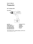
VEC1093DBD
Fu||y Automatic
Smart
Battery
E|ectro.ic
Charger
IMPORTANT SAFETYiNFORMATION, SAVE THESE INSTRUCTIONS
TO REDUCE THE RISK OF INJURY, USER MUST READ AND UNDERSTAND
THIS INSTRUCTIONAL MANUAL, THIS MANUAL CONTAINS IMPORTANT
INFORMATION REGARDING THE OPERATION AND WARRANTY OF THIS
PRODUCT, PLEASERETAIN FOR FUTUREREFERENCE,
4140SW
301hAve
R LJuderdJle FL33_12[JS
Toll Free: (S00) 6185178
VECI093DBD
Manual
050205
5/5/05
iMPORTANT
IS
NO£MAL
BAT[ERY
GAS MIXTURES -- WORKING
DANGEROUS.
3.
BATEERIES
G£NERAT£
FOR
R£ASON,
OPERATION.
This equipmer_
THIS
USING
YOUR
£XAC_Y.
To reduce
risk of bakery
the battery manufacturer
vicinity of battery.
Page
ii
SAFETY iNSTRUCTiONS
THAT
EACH
TIM£
BEFORE
FOLLOW
THE INSTRUCTIONS
2.
PM
F12ure
WARNINGS
I. RISK O£ £XPLOSW£
BAYT£RY
6:32
Review
employs
cautionary
parts
EXPLOSIVE
IT IS OF
CHARGER,
explosion,
{gRow
and
manufaclurer
YOU
GAS£S
UTMOST
READ
THIS
MANUAL
AND
markings
(switches,
on
relays,
these
products
etc.) that
area,
the
and
produce
unit MUST
on
arcs
be
or
sparks.
placed
not
less
or sold by the battery charger
manufacturer
R
To reduce risk o_ damage
disconnecRng charger¸
3
An extension cord should n_ be used unless absolutely necessary¸ Use of an
cord could resuh in a risk_ ire and eleclricshock, and will void warranty
a
until a properly
DANGER
may
resultin
a riskof fire,ele_ric shock, or i_ury to persons¸
ex{ens_N
cord
_
electdc plug
and
cord¸
must
be
U_e_,
make
is properly wired and
c that wire size is AWG#10
4
Do
nol operate
replacement
charger
(10 gauge)
with
pull by
plug
ralher fl_an cord
when
improper
extension
sure:
number,
in good
for 100
damaged
of the plug or cord
size, and
shape
cord
or plug
Do
to a
over 100
feel
qualified lechnician
dropped,
or olherwise damaged
charger; take itto a qualified service technician when
required¸ Incorrec_re-assembly may
_ reduce risk of electdc shock, unplug charger from outle_before atiem_ing
cleaning¸ _rning off conlrols wilhout unplugging will n_ reduce thisrisk¸
_
Do
screw
th_l
to rain, snow
or use when
_or
in
of your voice or close enough
2
Fresh water and soap
irlcase battery acid conlac_
3
Wear
secure
of
any maintenance
or
to come
to your aid when
an
1
R
_o
grounded
termin;iI
c_use an arc
3
4
from
This helps
(maintenance
6
Sludy
while
0
Area [lround
blown aw_y
7
Make
Sure gle
initial
6
M_Clrkle batteries
6
NEVER
6
Be extra cautious to reduce the risk_
skinrclothing, or eyes¸
touching eyes while working
with soap
and water¸ ifredness, pain or
or allow a spark or flame in vicinityof battery or engine¸
dropping
ilems such as dngsr
a LEAD-ACiD
electricalsyslem _her
can
cause an explosion¸
bracelels, necklaces and
battery only
FROZEN
when
working
high enough
nol use _e
with
to cause a
itis not intended to supply power
than in a _arier_rn_or application¸ Do
A
walches
a shoM-circuilcurre_
for charging dry-cellbatteriesthat are commonly
used with home
bur_ and cause i_ury to persons and damage
properly¸
CHARGE
Do noI
a metal tool onto battery This might cause sparks
or other eleclricalparl, which
a lead-acid batter_ A lead-acid battery can produce
severe burn¸
equipme_-grounding
and grounded 110/I
that
mus_ be connected
rep]_3ce
original
cover
plate
batteriesmay
BATTERY¸
to reduce riskof electricshock¸ Charger
is_luEpped
with an Am
the
center
screw
to a propedy
oLlt]f_ Cover
and
connect
plate
grounded
screw
to grounded
with
a
culler
ii
If a grouNdiNg
until
the
type
proper
by
a
receptacle
gullet
to be charged
by ref_lring
to the owner's
iTlanual
hFlite[y {tom vehicle
to charge
or to clean terl[lina]s
M_ke
sure
all accessories
in the vehicle
g;is flolrl
ceils
Do not overfill
For a
_ollow m_clnufact_rer's
charging
instrucRoris
h_s
is
been
aIw_lys
are off
[_lte does
sllch
b_;Rtery
_ls removing
remove
so _ls not
to
manufacturer
wi_houl
cell
or not removing
c_%ps
cell caps
while b[lt_ery is being charged
Gas can be furce{ully
or other nonmetullic
m_tted_Cll as a fan
not exceed
as far away
Connection
acid
charger
musl
set a battery
flol[1
directly
battery
above
Io drip
oil
in a c[osed-kl
be removed
as cables
battely
battery
manufacturer's
requRel[]enl
chalged;
charger
when
reading
area
or restrict
_lnd charged
3
Attach
clamps to batlery
chassis as h/dicat_d
Jn "Bakery
Outside
of Vehicle 'r s_eps 2, 4 and
allow
disconnect
clamps
DC ouIp_t
to touch
Follow
these
steps
wher_
may
cause
an explosion.
Position
Stay cle,q[
3
Check
AC
and
O[ fan
pohrity
NEGATIVE
Delermine
grounded
gravily
ventilation
from
battery
or filling
in any
will
corlode
and
battery
way
Oil shore
on top o{ charger
Never
1
gases
Precautions
and
R
permit
being
2
4
a proper
outlet
installed
in an electric
shock.
in Canada.
Connecl
cord having
conductor and a grounding plug¸ The plug mu_ be plugged inlo a properly in_aIIed
20 voltAC outlelin accordance with alllocalcodes and ordinances (see Figure IA)
allowed
1
to a low
batiery charger
appliances¸ These
DC
_ot
fit, have
ma_
result
use
this
appliance
electrician.
bFttJery firs_
charging
operate
Power
Cord
Safety
Charger should be grounded
certain
Locafion
,%llow bat[ery
TO
adapler
lab to oudet
b,qtt_ry should be well ventilaled
by using a piece of c;irdboard
NEVER
ATTEMPT
electrician
ma_e
_111bal_ery
n/_lnu_lc_lJrer's
specific
preczlu_ions,
charging,
and recommended
rates of charge
NEVER
NEVER
from
If it wiR
con_lection
is not
purge
excessive
free), carefully
4
vol_ge
_
Clean battery
terminals
Do not allow
corlosion
_o come in contacl with eyes
Add distilled
water
in each cell until battery
acid reaches level specified
by batiery
3
for charging
SCREW
Charge
battery Acid, acid particlesor corrosion may gel into eyes¸ Immediately flood eye wilh cold waler
(Eye Wash
Station)for at lea_ 15 minutes and seek medical atiention immediately
Use charger
by a qualified
If necess_Ky,
ground
do
not
qualified
D_termine
voltage
of battery
If it is necessary
to remove
NEVER pVice chargel
d_l m_lcJe charger
personal me_l
_d_lpler
adapter
Not avai|a_|e,
installed
by a
Loc[ltP charger
Remove
extending
Use
1
clothing protection¸ Avoid
Ifbattery acid contacts skin or cl_hing, wash immediately
irdladon occurs, seek immediate medical attention
9
will
2
and
4
8
ear of tab
with a
or shorbcircuilthe bakery
METAL
adapter
(like gee adapter
shown
in Figure1 B)
The temporary
adapler
should be used ONLY
as illustrated,
IT IS GROUNDED
Note:
Charger
should be nearby
eye pr_ection
smoke
be installed
adapter
alter
AC cord
Or pPJ_.
electrician.
ImpFoper
service or repaEr Es
wet
Another person should be within range
you work near a lead-acid batlery
complete
can
aN
N£VE_
quali[ied
Personal Safety
7
outlet
rigid
longer
resullin a riskof elec_ic shock or fire,and will void warranty¸
7
charger
i
is grGund_.
CERTAIN
immediately
6
not expose
°
outlet is not Ftvailable,
a temporary
this plug 1o a two pole receptacle
usin_
MAKE
Preparing
for di_ances
lake
Do nol operate charger if ithas received a sharp blow, been
any way; take itto a qualified service technician¸
I
Before
oufl_t
as those of plug on
electricalcondition; and
feet and AWG#8
6
not disassemble
_!_,_,
WARNING
that pins on plug of extension cord are the same
that extension cord
_
grounded
--
The green-colored
charger;
b
!
PIN(A)
j
of outlet plate
not recommended
I
GROUNDING
If a properly
grounded
n/ay be used to connect
engine.
Battery Safety
If an
i
DURING
IMPORTANC£
these instru_ions
and those published
by
of any equipment
you intend Io use in
Therefore,
if used
in a garage
or enclosed
than 18 inches above
the floor.
I • Use o_ an attachment
Figure
IN VICINITY OF A LRAD-ACID
of Dattery
(MEG,
which
N, _
post
to chassis
removing
AC
cord
h/ "B,3It_ry
5
Installed
{lore electric
in V{_hide 'r steps
is irista_]ed
ir_ a vehicle.
risk
of a spatk
near
the
to reduce
A spark
battery:
risk of d_c_mage by [mood, door,
bert% pulleys
posts
only after
oLlIIot
other
the battery
To reduce
DC cords
blades,
clamps
each
and
POSITIVE
other
(P(-)Sr
parls
or moving
th_ll can c,3use
R +) battery
post
near
k_ury
usually
6 _lnd _, _lnd
the
engine
battery
part
to persons
has larger
diameter
th_tn
pos_
rat battery
(as in most
is grounded
vehicles),
(connected)
see 6
iii
If POSITIVE
to the
chassis
post is grounded
If
NEGATIVE
to the chassis,
posl
is
see 6
VECI093DBDManual
5
6
050205
For negative-grounded
(POS, P +) ungrounded
engine
block
paris¸
Connect
For
away
from
batter_
body
When
vehicle¸
parts¸
Connect
clamp
battery
8
Do not charge
the
9
See operating
instructions
clip
iv
to carburetor,
or sheet-meal
body
(BLACK)
clamp
AC
metal
part
cord,
remove
from
of the frame
clamp
battery
or engEne
from
charger
Io
block¸
vehicle
while
for
the el_gine
lenglh
chassis¸
and
then
information¸
has been
To reduce
removed
from
risk
of a spark
a vehicle.
near
the
A spark
battery:
near
2
Check polarity
of battery
po_s
The POSiTiVE post (marked
POS,E
+) usually has a larger diameter
than the NEGATIVE
battery
po_ (marked
NEG, N,
)
Attach
a 24-inch
(minimum
length)
6 AWG
insulated
battery
cable to lhe NEGATIVE
battery
post
3
(marked
Connect
NEG,
N,
)
the POSiTiVE
from
the
clamp
battery
Io the POSiTiVE
as
possibler
Stand
as far
connecliorL
6
Carefully
connected
6
Set the
7
Wben
disconnecting
charger,
always
do so in reverse sequence
first connectfel/
while
as far away from battery
as practical¸
conne_
the NEGATIVE
(BLACK)
to the NEGATIVE
lerminal
dlarge
rate
to appropriate
A marine
(boat)
on
requires
board
NOT
designed
setting
battery
for
charger
must
be
do
n_
clamp
according
equipment
such
and
baltery
4
Note:
back
(RED) battery
removed
po_
face
to tbe
to battery
and
specfaRy
Charge
Charging
Automatic
is operating¸
of charge
Features
_'oNJrols alJd
Operating
terminal
battery
(marked
battery
free
end
POS,
P + or red)¸
when
making
of the
final
battery
cable
size¸
of connecting
charged
designed
_r
1
2
3
5
5
5
6
6
7
7
8
9
9
10
IntloductJon
block¸
of battery¸
Connect
POSiTiVE
(RED) clamp
to vehicle
Do not connect
clip to carburetor,
fuel lines or sheet-
gauge
disconnect
chargel
to POSITIVE
_ vehicle chassis or
fuel lines,
or engine
NEGATIVE
FoRow
_.hese steps
when
the battery
the battery
may
cause
an exptosion.
1
Page
of the frame
pox
battery¸
to a heavy
charger,
from
connect
part
connect
N, ½ ungrounded
block away from
disconnecting
remove
metal
PM
POSITIVE
(RED) clamp
from battery
Connect
NEGATIVE
(BLACK) clamp
Do rl_
gauge
posifive-grou_/ded
metal
7
6:32
vehicle,
connect
pox of balter_
to heavy
NEGATIVE
(NEG,
chassis or engine
5/5/05
procedure
on
shore.
marine
and
break
To charge
use.
This
unft
use.
is
J(]lca(ois
NSTrUCT[ON
_
Rate Selection
the Batter
Float Charglug
Equalizing
Enghe Staff
Recondition
Mode
AItematoi
Check
Approximate
Chal #n
Ca/e and Maiutenance
[roubleshooR
rimes
j
iNTRODUCTiON
Thank you for selecting the 40/20/70/4
Amp Smart Battery
Charger.
With
proper care and use, it will give you years of dependable
service, This battery
charger has a high charge rate of up to 40 amps, a low charge rate of 4 amps and
110
amps
of engine
starting
power,
It is designed
for charging
only
12 volt lead-acid batteriesconventional
automotive, maintenance-free,
marine
deep cycle and gel -- used in cars, trucks, farm equipment, boats, RVs and SUVs,
lawn mowers/garden
tractors, motolcycles, personal watelcraft, snowmobiles, ATVs
and various applications.
SAVE THESE |NSTRUCTiONS
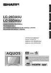
Smart Battery Chargers feature g-stage high-efficiency charging technology built-in
microprocessor control that ensures fast, safe and complete charging of serviceable
batteries.
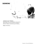
Charge Curve
STAGEONE
BEEP
This device
complies
witb
part
15
conditions:
(1) tbis device
may
not cause
any interference
receivedr
of the FCC
including
rules
harmful
i_erference
Operat[oll
is subject
interference,
that may
Io lhe following
and (2) this device
cause
undesired
mu_
_
BEEP
two
accept
operation¸
This equipment
bas been tested and found to comply with tbe limits for a Class B digital device,
pursuant to part 15 of the FCC Rules¸ These limits are designed
to provide
reasonable
prolectiol/
again_
harmful
radiate
radio
in_ructions,
guara_ee
harmfel
inlerfer ence
frequel_cy
may c_use h_rmful
that interference will
interference
equipment
off and
of the following
to radio
il/slallation
if
n_
This equipmel/t
in.ailed
and
used
interfererlce
to rEidio communications
n_ occur in a particular
in_allation
or television
Onr the user
or refecate
o increase
tbe separation
* Connect the
conneoted
andr
reception,
is encouraged
which
can
to try to correct
generatesr
in
However,
[f equipme_
be determined
the
uses and call
accordance
interference
with
tbe
tbere is no
does cause
by turning
by one
the
equipment
the dealer
receiving
antenna¸
between
equipment
into an outlet
or an expedenced
and
on a ci_uit
or more
radio/TV
iv
receiver¸
different
technician
from
for
that to which
help¸
tbe
CHARGING
COMPLETE
_e
measures:
* Reorient
• Consult
in a residel/fial
energy
receiver
is
Stage
One
-- Rapid Start Charge at 40 amps delivers maxJrnum charging
amperage to "wake up" any serviceable 12 volt battery and allows fol quick engine
starting in just 1 minute (based on a midsize vehicle battery at 50% charge level),
Whet] battery reaches a maximum safe predetermined
voltage, the charger will
automatically signal a "beep" and move into Stage 2 of the charging process.
VECI093DBDManual
050205
5/5/05
6:32
PM
Page
2
Stage TMZO -- Absorption
Charge maintains the maximum possible charge at a
constant, safe, predetermined voltage. During this phase, the charging voltage remains
constant, while the actual charging current is reduced to allow for the maximum proper
internal chemical energy transfel. At the end of Stage 2, the charger will automatically
move into Stage 3 charge mode.
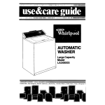
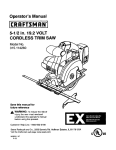
Controls
and
Indicators
CONTROLPANEL
DIGITAL READOUT
CIRCULATING PATtERN
Stage
Three
-- Top-Off Charge -- voltage is automatically
maintained
and
reduced to a predetermined
level while current is adjusted for a safe, effective battery
chalge. At the conclusion of Stage 3, the unit will BEEP signaling the completion of
the charging cycle.
The Automatic Float Charge feature is ideal for maintaining a battery. It automatically
tops off battery as needed to keep battery fully charged all the time.
FEATURES
. This unit has four charge rate settings, accessed by the 4/10/20/40
a) 4 amps: smaller batteries,
b) 10 amps: mid-sized
as in lawn mowers,
batteries,
c) 20 amps: automobiles
snowmobiles,
AMP button:
motorcycles,
BUTTONS (FROM
LEFT TO RIGHT):
Battery
Type (Step 1) -- allows the user to seled Wet, Gel or AGM type of battery
for efficient and safe charge. Most automotive batteries are Wet batteries. Refer to tile
battery n/anufacturer's specifications for battery type.
etc.
4/10/20/40
AMP (Charge
Rate Selector) (Step 2) -- allows tile user to select
the charge rate based on battery size. This selection and the actual battery charge
rate are monitored by the microprocessor. The charger will stop charging if the rate
is too fast or too slow for the battery size or condition.
as in small cars
and light trucks
d) 40 amps: large truck batteries,
FUNCTION
banks of RV batteries
. 110 amp engine start
• Automatic
1 10 AMP Engine Start -- places tile charger in an engine start sequence. This
button will not be activated unless the charger is in the 40 amp charge mode; set the
4/10/20/40
AMP button to 40 amps first to activate this button.
Temperature Compensation
• Battery type selection
- Digital
diagnostics
- Alternator
voltage and battery voltage check
• Digital display
charged
shows
cl/arge
rate, operating
mode,
fault codes
and FUL when
• 1-minute engine start
• 3-stage high-frequency
switch mode automatic
- Spark resistant reverse polarity
. Built-in battely
• Lightweight,
reconditioning
high-efficiency
rapid charging
and short circuit protection
for user
(desulfate)
design
Battery
Recond.
-- is an automatic mode that, once started, continues for 24 hours
and then stops, A series of electrical pulses breaks the crystalline form of lead sulfate
to return these chemicals into useful battery electrolytes. More than 24 hours may be
needed to restore. Periodic reconditioning
is recommended to maintain a bauery's
optimum performance.
However, if 5 cycles does not improve battery performance,
discontinue and lecycle the battery.
Battery
Voltage
(Aiternatar
Voltage
Check) -- is a quick check that measures
tile battery voltage, Tl/is check is repeated at various electrical load levels and tile
tests allow the user to determine if tile alternator can keep up with the loads,
• Internal short circuit protection
- Cables
and clamps self-stored
- Reverse polarity
• Microprocessor
• Compensates
• Equalization
indication
control (Digital
Smart Control)
for low AC from extension
Mgh frequency
power
cord use
function
- Battery recondition
function
2
3
VECI093DBDManual
050205
5/5/05
6:32
PM
Page
4
OPERATING
INDICATOR:
Large (.375")
3-Character
Digital
indicates the various conditions and/or
St_mJsCodes are described
Display in the upper left of the control panel
status codes:
in the following
chart and on the back of charger.
iNSTRUCTIONS
Ensure that all installation
and operating
instructions and safety
precautions
are understood
and carefully
followed
by anyone
installing or using the charger. Follow the steps outlined in "important
Safety Instructions"at the frontof thismanual.
Charge
Rate Selection
After charger clamps are correctly connected, plug in the charger to a 120 volt AC
outlet and the charger will show a circulating pattern on the Digital Display, indicating
power has been applied. Select the proper charge current rate based on battery size.
Press the 4/10/20/40
AMP button and the charger will begin charging at 4 amps.
Pressing the 4/10/20/40
AMP button again will advance the charge rate to 10
amps, again to 20 amps, and again to 40 amps. Pressing the switch again will turn
OFF the charger output and the display will show "000,"
Note:
The only time the selected charge rate does not display at the full selected rate
iswhen thebatteryisnearly full
and chargingat eithersteptwo or three.The
displaywill be showing a reduced charge rate.To return t_ 2A, press the
2/20/40 AMP button.When thebatteryisfully charged,thechargingcomplete
and "FUL" is displayed on the Digital Display.
WARNING
if Digital
Display shows "FO2",
the connection
to the battery
terminals
is bad. Follow
the steps outlined
in "important
Safety
Instructions"
at the front
of this manual
to disconnect,
clean battery
terminals,
then reconnect,
GEL -- lights when battery type selector is on GEL battery type
if Digital
Display
shows
"F06",
the
Red
(POSiTiVE)
and
Black
(NEGATIVE)
clamps
are incorrectly
connected
to batter]
terminals.
Follow
the steps outlined
in "important
Safety
instructions"
at the
front of this manual
to disconnect,
then reconnect
in correct polarity.
AGIV[ --
Charging
CONTROL
WET --
Float
allows
loss of
to the
PANEL LED INDICATORS:
lights when batte W type selector is on WET battery type
lights when battery type selector is on AGM
battery type.
Charge
-- ligltts when automatic charge monitoring is active. This feature
a battery to maintain its charge over long periods of non-use. If there is any
power to the charger once power is restored charger wil! automatically return
default settings. Battery selector type would be "GEL".
Battery
Voltage
--
lights when battery voltage
Alternator
Good -- lights when
keeping up with the electrical load.
BUTTON
Equalize
is displayed.
load or not load checks show tile alternator
(TO THE RIGHT OF LEDS):
--
a recessed button used to start the equalization
process.
is
the
Battery
1, Press Battery Type selector unti! desired
battery type LED lights,
Note: The defaultselection
is"'GEL"type battery.
2. Press 4/10/20/40
AMP button to begin charging at the 4 amp rate; the unit
sounds a beep and the cl/arging current LED lights. The charger starts cl/arging
at 4 amp rate automatically if 4/!0/20/40
AMP button is not pressed within 3
minutes after applying AC power.
If the Display on the charger varies between "E03" and the amp rate, the battery
is sulfated and the charger is trying to give it some charge. If aRer approximately
2 hours the display.just shows "F03", tl/erl the battery will not charge,
Charger
charging
occasionally
sounds
stage changes.
a beep
and
displays
"0,0"
during
sell-test or
3. Pressing the 4/10/20/40
AMP button again advances charging rate to 10
amps, pressing once more advances charging rate to 20 amps, and again to 40
amps. (Pressing the button again will turn OFF the charger output arid the Display
will show "000",) This selection and actual battery charge rate are monitored by
the microprocessol,
and the unit will stop charging if the selected late is too fast
or too slow for battery size or condition.
As the battery nears full charge capacity,
to a lower charge rate.
tile unit's output will automatically
drop
Pressing
the4/10/20/40AMPbutton
repeatedly
advances
tostandby
mode;
theunitsounds
a beep,
displays
"000"andstops
charging.
4.Thebattery
charger
displays
thecharge
current.
Toviewtilebattery
voltage,
press
BATTERY
VOLTAGE
button.
Thecharger
willsound
a beepanddisplay
the
battery
voltage
for3seconds,
thenreturns
todisplaying
thecharge
current.
B.Thedisplay
shows
"FUL"
whenthebattery
isfullycharged.
6.Follow
thesteps
outlined
in"Important
Safety
Instructions"
atthefrontofthis
manual
todisconnect.
AutomaticFloat Charging
Automatic
Float Charging
is ideal for m_intaining
1, Keep tile AC power and battery conrlected
2. The chargel
a fully charged
after battery
is fully charged,
monitols the battery and tops it off as needed.
Note:
battery voltage,
press tile Battery Voltage
button.
Charging can be termblated by pressing the charge rate selector button at any
time when unit is charging. After AC power interruption, chargittg restarts at 4
amp rate automatically
and the battery
type
will default to "GEL",
size is not
batteries.
known,
charge
at
the
4 amp
rate,
DO
tO nolrrlah
the Battery"
section on page 5 of this manual.
8. Push the Battery Type Selector Switch until "WET"
only work if a WET battery is selected,)
is displayed.
(This mode will
9. Choose tlle correct charge rate and start charging. You can check the battery
voltage by pushillg the Battery Voltage button. This wil! trigger the Battery Voltage
indicator button.
11, Every hour, the temperature should be checked by touching the battery. If the
battery is hot to the touch, stop the charging and allow the battery to cool,
12. The w)ltage rises, but does ilOt go over 15.3v to 16.2v (2.55-2.7v
depending Ol_ ambient temperature; it will automatically adjust.
13. The "WET"
14. The digital
Engine
WARNING
if battery
overcharge
brick
7, Follow the steps in the "Charging
10, Push the Equalize button at any time and the battery will automatically begin to
equalize in 4 amp limited current. Note that in order to push the recessed buuon
you will need a small pin or ballpoint pen.
battery.
3, The Float Charge indicator lights; the display shows charge current when topping
off the battery and returns to "FUL" when completed,
4. To view
6, Fill the battery with distilled water according to the manuf_]cturer's instructions.
Since batteries may rapidly bubble while being chalged, remember to lefill (only
with distilled water) after the equalization
process is complete and the voltage is
NOT
LED flashes while the charger
readout
will show "FUL" whell
is in equalize
the equalization
mode.
process is complete.
Start
Tile EHgine Start function can supply ! 10 amps for engine starting.
1, Set the 4/10/20/40
AMP button to 40 amp mode and immediately
110A button switch to activate the Ellgille Start mode.
Equalizing
per cell)
2. The digital
display
will countdown
from "999"
pless the
to "000."
Equalizing is the process by which the fluid in each of a battery's cells is equalized.
This process occurs after charging is complete,
3. When the "000" count is reached and begins flashing oil the Display, the vehicle
is ready to start.
/_,_
WARNINGS
4. Crank the engine using manufacturer's
guidelines, typically irl 3 to B second
bursts. The high current engine starting function requires a resting/cooling
period
between tries. The charger will switch back to regular charge mode aRel
5 seconds and will not allow operation in this mode tot 4 minutes, Wait 4 to B
minutes before a second attempt at starting the engine, if needed.
* NEVER TRY TO EQUALIZE A GEL OR AGM CELL. THE RESULTING
EXPLOSION COULD CAUSE PROPERTY DAMAGE, SERIOUS iNJURY
AND/OR
DEATH,
= Remove
or disconnect
the
vehicle's
battery
when
equalizing.
The frequency wllich the equalization
process needs to be run depends on the use of
the battery. The more the battery is used, the more undercharged
it becomes; thus the
more frequently the battery should be equalized.
1. Do not use this mode on sealed or valve regulated
meant for wet (unsealed/vented)
batteries.
2. Make sure there are no flammable
batteries,
sources near the recharging
3, Wear safety glasses, gloves and protective
This mode is only
sigllt.
clothing.
4. Remove battery from vehicle. MAKE SURE THAT THE BATTERY HAS GOOD
VENTILATION, Tile process causes the release of hydrogen and oxygen. An
accumulation of these gases presents a real danger of explosion.
5. During the rest period, the battery is charging at 40 amps. After engine starts,
follow the steps outlined in "lmportarlt Safety Instructions" at tile front of this
manual to disconnect,
Recondition
Mode
Whenever a lead-acid battery begins to discharge, lead sulfate, an insulator, begins
to build up on the battery's internal plates. This reduces the ability of tile battery to
hold a full charge. When that battery has an immediate charge, most of the lead
sulfate is dissolved alld the plates are free of this illsulation. If a bauery remains in a
discharged condition over a longer period of time, the lead sulfate changes to a hard
clystalline form, making a full charge difficult to achieve, Reconditioning
may "save"
a sulfated battery.
5. Open the battery cap, if removable.
6
7
BATTERY RECONDITION
MODE should only be used with 10 Amp Hour (Ah) or
larger capacity lead-acid batteries, Charge the battery to be treated for 20 minutes,
before using RECONDITION
Mode. Observe the Digital Display tar any codes. This
initial charge will check the battery for shorted cells (F01), open cells (FO3) or battery
too low to accept a charge (FO2), and to ensure the battery carl take a charge. If
code (FO3) is displayed, change to the BATTERY RECONDITION
MODE.
Remove or disconnect
the vehicle's
battery when reconditioning.
3, DES appears on the display
moving bars.
button to start the process,
for 3 seconds, then it changes to three horizontal
4. The process takes 24 hauls and stops automatically.
when complete.
Alternator
Part
Voltage
The display
shows "O00"
(Turn OFF all vehicle's accessories): The battery must be fully charged
before testing the alternator. Run the engine long enough to achieve
normal idle speed and verify there is a no-load voltage,
1. Press Alternator Check to star[ the check.
2, Alternator Good LED will light to indicate the alternator is good, or F07
will display if alternator output voltage is out of typical operation range,
3, Press Alternator Check again to stop the test,
Part 2
Under Load (Accessories ON): Next, load the alternator by turning
accessories as possible (except for A/C and DEFROST)
1, Press Alternator Check to start the check.
on as many
2. Alternator Good LED will light to indicate the alternator is good, or F07
will display if alternator output voltage is out of typical operation range.
3, Press Alternator Check again to stop the test,
If the first alternator check indicates a good alternator and the second indicates the
alternatol is bad, the problem could stem from: loose fan belts, an intermittent diode
failure or possibly bad connections between tile battery and alternator and/or ground.
Notes:
BATTERY VOLTAGE button
is disabled
in Alternator
Check mode.
F07 may display because someor_
has added
a number
of accessory loads
on the charging
system,
thereby
increasing
current
demand
from
the
alternator.
MAKE SURE THAT THE ALTERNATOR
IS RATED TO SUPPORT THE
APPLICATION.
This check
vehicle.
Check only
may
not
be accurate
for every
make,
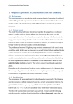
TIMES
The 4/10/20/40
Amp
12 Volt Smart
Battery
Charger will automatically
adjust the charge rate as the battery becomes charged and stop when the battery is
fully charged, Deep cycle batteries may require longer charging time,
For estimates of the time it takes to charge a battery, refer to the following
75%
in battery
50%
0%
25%
14 HRS
at 4 Amp rate
3,5 HRS
7 HRS
10,5 HRS
at 10 amp rate
!,4 HRS
2,8 HRB
4,2 HRS
5,5
HRS
2,1 HRS
2,8
HRS
at 20 Amp rate
1 HR
1,5 HRS
at 40 Amp rate
1 HR
1 HR _
* Not recommendedfor charging batteries lessthan 80 Ah
1 HR _
1-2 HRS
manufacturer
and
model
In ttlOSt cases, battery charging tittles will vary depending
on the size, age and
condition of tile battery. Smaller batteries should be charged at a lower rate (4 amps)
and an extra hour added to chalge time,
CARE AND
MAINTENANCE
With proper care and minimal maintenance,
the 4/10/20/40
Smart Battery
Charger
will provide years of dependable
performance,
manufacturer recommends:
* After each use, clean the battery charger clamps -fluid that will cause corrosion of the clamps,
- Clean the outside case of the charger
solution,
• Do not allow
liquid to enter the charger,
• Keep the charger
cords,
cords loosely
Amp
12 Volt
service. Fo_ maximum
be sure to remove any battery
with a soft cloth and, if necessary,
Do not operate
coiled during
when charger
mild soap
is wet,
storage to prevent damage
to the
WARNINGS
• Do not use charger if cords or clamps have been damaged in any
way -- cab Technical Support toll-free at (800) 618-5178.
,_ There are no user-serviceable parts in this unit.
• Do not open the unit. in the event of malfunction,
it must be returned
to manufacturer
for professional testing and repair. OPENING THE
UNIT WiLL VOiD THE MANUFACTURER'S WARRANTY.
of
12 volt systems.
8
table.
The times shown irl the table above are approximate and refer to a BO All automotive
battery. For example, a 50 Ah (12 volt) battery is discharged
(50%). How long
should it be charged at the 10 amp rate? See the chart above under "NO%" and "at
10 amp rate."
Check
1
No Load
CHARGING
Percent of charge
1, Make sure the charger is in initiation state with a circulating pattern on the
display or in charge OFF rhode with "OOO" on the display. If not, press
4/10/20/40
AMP button repeatedly until "OOO" shows on the display.
2. Press the Battely Recondition
APPROXIMATE
9
TROUBLESHOOTING
Display
Indications/Common
Problems/Possible
Solutions
No Far.lions
• Check and make sure the charger
• Follow the steps outlined
F01 --
Internal
is plugged
in the Operating
Shorted
into a live 1 ! 0/!
20 volt AC outlet,
Instructions section.
Celt Battery
If the battery being charged has an internal shorted cell, tile F01 wil! show, We
recommend taking your battery to a certified automotive service center for evaluation.
F02 -Charge
When
Bad Battery
F02 appears,
Connection
or Battery
the most common
Voltage
Too Low
to Accept
cause is poor connectior_ to battery,
- Follow the steps outlined in "Important Safety Instructions" at the front of this manual
to disconnect AC cord and clamps, clean battery terminal and reconnect.
• If the situation persists, we recommend
service center for evaluation,
F03
--
Appears
Sulfate
or Unchargeable
taking your battery to a certified
automotive
Battery
when the battery is highly sulfated and cannot accept normal charge current,
- Follow the steps in "Recondition
Mode"
• Follow the steps in "Equalizing"
to equalize
to recondition
the battery.
the battery.
. If the situation persists after reconditioning
and equalizing,
we recommend
your battery to a certified automotive service center for evaluation,
F04 --
Overtime
taking
Condition
Appears when charging time exceeds 18 hours. You may be using a charge current
rate too low for a large battery. Select highel charge rate to charge the battery.
F05 --
Overheated
The ventilation
be blocked.
Condition
grill that p=events the air from flowing
in and out of the charge= may
• Follow the steps outlined in "Important Safety Instrudions" at the front of this manual to
disconnect AC cord and clamps, allow the unit to cool for 30 mint_es and rgconnect,
• Make sure there is ample ventilation
F06 -- Reverse
before resuming
operation,
Polarity
The connections to the battery's POSITIVE and NEGATIVE terminals are incorrect,
Follow the steps outlined in "Important Safely Instructions" at the front of this manual
to disconnect AC cord and clamps and reconnect to battery with correct polarity,
F07 -- Alternator
Alternator
Charging
Voltage
output voltage
a Very
is out of typical
operation
range,
Cold Battery
If the battery to be charged is very cold (in temperatures below freezing -- 0°C/32°F),
it cannot accept a high rate of charge. The initial charge late will be low. The charge
rate will increase as the battery warms, Never attempt to charge a frozen battery,
lO
11
FIVE YEAR LIMITRD WARRANTY PROGRAM
This limited warranty
progr.Rm is the only one that applies to INs producl, and il sets futth _ill the
responsibilities of Vector Manu_cluringr
reoz_rding this product¸ There is no olher warrant_L o_her than th_
de_ribed
helein
This Vector Manu_c[urirlg
produc[ is warranted.
_ the origirlal purcha_r
onI_ to be flee of de_cts in
materials and workmanship
for five years from lhe date of purchase without additional
charge¸ 1]le
warra_
does t_t extend [o su_quent
purchasers oF users a_mJ_clurer
will _ot b_ _ponsibJe for any
_mounl of damage irl excess of [he relail purchase pri_ of lhe product under any _ir_um_ances
Incidental
and consequential damages a_ si]ecificaIiy exclud÷d from coverage under Ibis warran_
This product is no_ ir_ended for ¢ommel_i_l use Tills warr_y
does rlo_ apply to acce_ories or damage Io
units from misuse or incorrect ir_aIiation
Misuse includes wiring or connecting Io improi_r polarily Rower
RETURN/REPAIR POLIC_ Dereclive products, other lhan accessories, may be rc4ur ned postage prepaid Io
marlL_ctu_
Any defec[Jve produce o_her than arxessoriesr that is _turrled to manufacturer wRhin 30 days
of the date of pu_hase will be replaced free or charge¸ If such a product is returned more than 30 days
bul less than five years from the pu_hz_se dale. manu_urer
will repair lhe unit o_ at i_ option. _epi_ce it
free of cha_e
If the unit is i_.pairedr new or reconditioned
replacement paris may be used. al manu_cturer_
o_ion
A
uni_ may be replaced wi_h a r_w or re_ond_ioned unit of the same or compa_ble
design¸ [he repaired or
rq_laced unit will the_l be warranled under lh÷ lerms o[ the remainder o[ the WalTanty period The customer
is lesponsible _r ti_e shipping cha_es on all returned Re_ after 30 days¸ During [he warranty period.
manu_c_urer will be responsible for the return shipping charges¸
LIMITATIONS: This warranty does not cover accessories, bulbs, f_es and batteries, defers resulting _om
ilormal wear and tenor(including
chii]Sr smatches, abrasionsr discolo_ion
or _ading due _o usage or ¸
exRos_re Io sunIigI_, a_cidents, damage during shipping _o our service _ciiity. alterationsr uilaulhodzed
or _epai_ negJed, misuse, abuse. _iIure Io follow instructions for care and m aintena r'.C.erfire. flood and
Acts of God
If your problem is r_ covered by [his warrant,
re1_air informalion
and charges,
if applicable
www ve_;torm_g corn
call _¢hnical Supporl at (800) 618-517_
_r genel_l
You may also co,act
us through our website a_
STATE LAW RIGHTS: [his warranty g_es you specific legal rigl_
Some _ales do nol allow ]imilalions on
how long an implied war_
Ias_s or tile excJusion or limit_Jon o1 it_idental or consequential damages.
so the exclusions or Iimitalior m _ated herein may nol apply l_is warranty gives _he RUrChaser specific lega]
righLs_ _her ¸ righLSr which vary from state _ _a_r may apply
TO REQUEST WARRANIY
SERVICE FOR THIS PRODUCT: Conta_ Technical Suppo_ by [eiephor _r _X or
mail _ee below)¸ We suggest th_ you keep the original Rackaging in case you need to ship lhe unit¸ Wherl
returning a product, include your name. addre_r
phone numbe_ dated s_les re(eip_ _r ¢oi_I and a
des_rii_ion of the reason _r re_um and product serial numbe_ After repairing or replacing _he unil. we will
make every effort _ re_urrl _ to you wilhin four weeks¸
WARRANTY ACTIVATION:
Please complete Warran_
Activation Card and mail _o Vector Manu_uring
Ei_ter "VEC1093DBD'r
as Model and _40/20/I
0/4 Amp 12 Volt Smart Autotoxic
B_ery Charger"
Rroduc[ _pe
All Ve_[or produc_ must be _gistered within 30 days of purchase _ act _e
Mail ti_e completed regis_ra_ion _rmr along with a copy of _he origina] sales r_ii>t
to:
as
this warranty¸
ATIN: CUSTOMERSERVICE
4140 SW 3Olh Aver R hudeldale, FL33312
* TOLLFREE:(800) 618-5178 ° PAX:(954) 584-5556
WARRANTY IS NON-TRANSFERABE AND NON-REFUNDABLE
BDO50205
© 2005 VECTC)R MANUFACTU[qNG
MADE IN CHINA
12