1
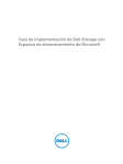
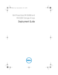
BENEFITS VIDEO BENEFITS STUDY PERFORMANCE REPORT MANAGEABILITY STUDY TCO STUDY A Principled Technologies configuration guide commissioned by Dell Inc. TABLE OF CONTENTS Table of contents ............................................................................ 2 Introduction.................................................................................... 4 Features of the new Dell PowerEdge R410 .............................. 5 Features of the Dell PowerVault MD3200i Storage Array ........ 6 About Dell OpenManage .......................................................... 7 About Microsoft Windows Server 2008 R2 SP1........................ 7 About Microsoft SQL Server 2008 R2 ....................................... 8 About Microsoft Exchange Server 2010 SP1 ............................ 8 About Microsoft SharePoint Server 2010 ................................. 8 About Microsoft Dynamics GP 2010 ......................................... 9 About Microsoft System Center Essentials 2010 ...................... 9 We show you how—Setting up your Dell 2-2-1 Configuration ........ 10 Cabling..................................................................................... 11 Setting up the switches ........................................................... 12 Setting up the shared storage and networking ...................... 14 Preparing the failover cluster and creating the management virtual machine ....................................................................... 18 Converting your existing physical servers into virtual machines ................................................................................................. 21 Adding storage volumes to the virtual machines ................... 22 Creating an optional secondary Domain Controller/Active Directory virtual machine ....................................................... 22 Summing it all up .......................................................................... 24 Appendix A – Setting up the shared storage and networking ......... 25 Adding the Hyper-V role ......................................................... 25 Installing the failover clustering feature on the Hyper-V host servers ..................................................................................... 25 Installing the PowerVault Modular Disk Storage software .... 25 Configuring the Modular Disk Array using the Modular Disk Configuration Utility................................................................ 26 Configuring the second host using the Modular Disk Configuration Utility................................................................ 28 Creating the disk groups and volumes using the PowerVault Modular Disk Storage Manager .............................................. 28 Teaming the Public network adapters .................................... 30 Defining a host group using the PowerVault Modular Disk Storage Manager..................................................................... 30 Appendix B – Preparing the failover cluster and creating the management server ...................................................................... 32 Creating a self-signed certificate ............................................ 32 Installing Dell OpenManage Server Administrator 6.5 ........... 32 Running the Validate a Configuration Wizard ........................ 33 Creating and configuring the cluster ...................................... 33 Configuring the networks for cluster access .......................... 34 Configuring the management server ...................................... 35 Installing Hyper-V Tools and failover clustering tools ............ 36 Installing Systems Center Essentials 2010 .............................. 36 Configuring Systems Center Essentials 2010 .......................... 37 Adding the failover cluster as a virtual machine host in SCE 2010 ........................................................................................ 38 Importing the Dell PRO Enabled Management Pack into SCE 2010 ........................................................................................ 39 Appendix C – Creating and configuring the virtual machines .......... 40 Migrating a physical server to a virtual server ....................... 40 Creating an additional virtual machine in SCE 2010 ............... 40 Configuring a virtual machine in SCE 2010 ............................. 41 Configuring the Live Migration networks for the virtual machines ................................................................................. 42 About Principled Technologies ...................................................... 45 INTRODUCTION Dell™ 2-2-1 solutions help companies by simplifying the design, ordering, and deployment of a virtualized infrastructure. Choosing a proven architecture designed by Dell to meet your needs allows you to confidently deploy an optimal solution without the time requirement and hassle of compiling your hardware solution piecemeal. You also get to reap the benefits of Dell’s best practice recommendations and guidelines. In this guide, we take a look at the pieces Dell provides you to create a highly available virtualized infrastructure, and we take you step by step through the process of setting it up. Dell 2-2-1 solutions follow the 2-2-1 model, which means the solution is comprised of two servers, two switches, and one storage array. Our virtualized architecture consists of two Dell PowerEdge™ R410 servers with Intel® Xeon® processor E5630s as host servers, two Dell PowerConnect™ 5524 switches, and one Dell PowerVault™ MD3200i storage array. Dell adds the software you need to help manage your business, including Dell OpenManage™, and the following Microsoft® applications: Exchange Server 2010, SQL Server™ 2008 R2, SharePoint® Server 2010, Dynamics® GP 2010, and System Center Essentials 2010. All servers (both physical and virtual) ran Microsoft Windows Server® 2008 R2 SP1. We show you how to combine these components into a robust infrastructure with the power to support five virtual machines (with the option of adding a sixth virtual machine as a secondary Domain Controller running Active Directory®) for your growing small business while leaving room for future growth. For the results of our performance testing of this solution, see our companion performance report. To learn more about other aspects of server virtualization Dell 2-2-1 solutions: High-availability virtualization with Dell PowerEdge R410 servers A Principled Technologies configuration guide 4 with Dell 2-2-1 solutions,, click the report tabs at the top of page one. For a general overview of server virtualization, we suggest starting with either the Benefits study or video. Features of the new Dell PowerEdge R410 Figure 1: The new Dell PowerEdge R410 server. The Dell PowerEdge R410, powered by Intel Xeon processor E5630s, offers many new features for maximizing performance and for minimizing operational expenses, including the following: Power. The Dell PowerEdge R410 includes enhancements that let it use less energy than many older servers do, so your potential power savings are dramatic. Processors. Two Intel Xeon processor E5630s power the Dell PowerEdge R410. These processors provide a good balance of performance and power savings through several Intel technologies. Enhanced Intel SpeedStep® Technology enables high performance while also saving power, and the Turbo Boost feature allows for dynamic clock speed increases for additional processing power when your workload requires it. For more information, visit http://ark.intel.com/products/47924. Management. The Dell PowerEdge R410, like all late-model Dell servers, comes with the Dell Lifecycle Controller. This tool simplifies server management by providing a single interface for management functions and by storing critical system information in the system itself. There are no CDs or USB keys to keep track of for drivers or firmware. Storage. The Dell PowerEdge R410 holds up to 8 TB of internal storage, which is ample capacity for a small business server. Memory. The Dell PowerEdge R410 holds up to 128 GB of RAM, many times the RAM capacity of older small business Dell 2-2-1 solutions: High-availability virtualization with Dell PowerEdge R410 servers A Principled Technologies configuration guide 5 servers, allowing for powerful flexibility with virtualized database solutions. To learn more about the Dell PowerEdge R410, visit www.dell.com/downloads/emea/products/R410_spec_sheet.pdf. Features of the Dell PowerVault MD3200i Storage Array Figure 2: The Dell PowerVault MD3200i storage array. The Dell PowerVault MD3200i storage array is an entry-level storage solution designed for virtualized environments where high availability is a must, and offers the following features: Ease of use. MD Storage Manager software offers an intuitive interface that makes management easy, allowing you monitor multiple systems through a single interface. It offers an Recovery Guru that automatically launches to alert you of problems and helps you solve them quickly. The power to handle large databases. The four iSCSI ports on the MD3200i offer twice the performance of earlier MD storage arrays, which enable you to handle the storage demands of large databases and to support solid state drives (SSD). Data protection options. Snapshots, Virtual Disk Copy, and self-encrypting drives are three features that help you protect your data. Dell 2-2-1 solutions: High-availability virtualization with Dell PowerEdge R410 servers A Principled Technologies configuration guide 6 To learn more about the Dell PowerVault 3200i, visit http://i.dell.com/sites/content/shared-content/datasheets/en/Documents/PowerVault_MD3200i_and_MD3220i_Spec_S heet.pdf. About Dell OpenManage Dell server configurations come equipped with Dell OpenManage software, which brings together network and systems management applications built using industry-standard specifications. Dell OpenManage operates seamlessly with systems management consoles such as Microsoft Systems Center Essentials to bring you all the tools you need to manage your infrastructure in one place. To learn more about Dell OpenManage, visit http://www.delltechcenter.com/page/Dell+OpenManage+101. About Microsoft Windows Server 2008 R2 SP1 Windows Server 2008 R2 SP1, the latest release of this server operating system (OS) from Microsoft, includes many features that can benefit your business, including the following: Virtualization. Microsoft Windows Server 2008 R2 comes with Microsoft Hyper-V, which you can use to create and run virtual machines. These virtual servers, which are often more powerful than your previous physical machines, can host your critical business applications and databases. Virtual machines, while allowing you to isolate business functions for security or regulatory reasons, are the backbone of high availability in that they can be easily migrated from one server node to another node in a failover cluster when needed. Simplified installation. The wizard-based setups of Windows Server 2008 R2 make the installation and configuration process considerably simpler than in past versions. Windows Management and updated components. Microsoft Windows Server 2008 R2 includes a revamped Server Manager console that contains almost all server management Dell 2-2-1 solutions: High-availability virtualization with Dell PowerEdge R410 servers A Principled Technologies configuration guide 7 functions, including the ability to quickly add roles and features to your server. To learn more about Microsoft Windows Server 2008 R2 SP1, visit http://www.microsoft.com/download/en/details.aspx?id=5842. About Microsoft SQL Server 2008 R2 SQL Server 2008 R2 is the latest release of Microsoft’s database management platform. As with each release, Microsoft has added new features to expand on the capabilities of their Database Management System (DBMS) platform. Where earlier versions of SQL Server required database administrators to rely primarily on either inhouse applications or third-party tools to monitor multiple instances, SQL Server 2008 R2 simplifies multi-server management. To learn more about Microsoft SQL Server 2008 R2, visit http://www.microsoft.com/sqlserver/en/us/get-sql-server/tryit.aspx. About Microsoft Exchange Server 2010 SP1 Microsoft Exchange Server 2010 SP1 equips you with a robust communications platform that can also give your users anywhere access, increasing their mobility. Other key features of Exchange Server 2010 include Unified Messaging, Mailbox Resiliency, archiving, and access to the Outlook Web Application. To learn more about Microsoft Exchange Server 2010 SP1, visit http://www.microsoft.com/download/en/details.aspx?id=21570. About Microsoft SharePoint Server 2010 Microsoft SharePoint Server 2010 is the latest version of this very popular and flexible collaboration software. It allows users to create collaborative Web sites and to create and manage their own workspaces. Some of its key features include SharePoint 2010 Dell 2-2-1 solutions: High-availability virtualization with Dell PowerEdge R410 servers A Principled Technologies configuration guide 8 Communities, which lets users share ideas and information from a single platform; the SharePoint Search feature, which lets users find other people and information quickly; and SharePoint 2010 Insights, which gives users an improved ability to access databases, reports, and business applications. To learn more about Microsoft SharePoint Server 2010, visit http://sharepoint.microsoft.com/en-us/Pages/default.aspx. About Microsoft Dynamics GP 2010 Microsoft Dynamics GP 2010 business management software allows you to manage all aspects of your company’s finances, including sales, supply chain management, payroll, manufacturing, and project and services management. Through it, you can gain greater control and insight into your business, improve your operating and profit margins, and better drive your company’s growth. Dynamics GP 2010 simplifies the setup process so that implementation is easy and quick, and Microsoft designed it to be highly scalable and compatible with existing technologies. To learn more about Microsoft Dynamics GP 2010, visit http://www.microsoft.com/en-us/dynamics/erp-gp-overview.aspx. About Microsoft System Center Essentials 2010 Microsoft System Center Essentials (SCE) 2010 software, which now includes System Center Virtual Machine Manager (SCVMM) 2008 R2 technology, provides you with a centralized management solution from which you can configure, maintain, modify, and monitor the physical and virtualized servers in your infrastructure. Dell PRO-Pack (Performance and Resource Optimization Pack), when used in conjunction with SCE 2010, helps provide simplified, proactive management for physical and virtual Dell 2-2-1 solutions: High-availability virtualization with Dell PowerEdge R410 servers A Principled Technologies configuration guide 9 servers, through such actions as alerting SCVMM of the need for live migration of VMs to another server in the cluster. With SCE 2010 and Dell PRO-Pack, it is easier than ever to monitor your configuration and quickly address any issues that should arise. To learn more about Microsoft System Center Essentials 2010, visit http://www.microsoft.com/en-us/server-cloud/systemcenter/essentials.aspx. WE SHOW YOU HOW—SETTING UP YOUR DELL 2-2-1 SOLUTION For this guide, we assume that you have an existing infrastructure server running Active Directory Domain Services (AD DS), Domain Name Services (DNS), and Active Directory Certificate Services. We also assume that you have existing physical servers dedicated to each business application, including SQL Server, Exchange, SharePoint, and Dynamics GP. We will show you how to set up your 2-2-1 hardware, create a virtual management server, perform a physical to virtual (P2V) conversion of your existing setup, and create a secondary Domain Controller. Figure 3 shows the hardware that comprises the Dell 2-2-1 solution we tested. Quantity 2 2 1 Name Dell PowerEdge R410 Dell PowerConnect 5524 Dell PowerVault MD3200i Function Host servers Switches Storage array Figure 3: The hardware that comes with the Dell 2-2-1 solution we tested. Our Dell 2-2-1 solution had the following software requirements (in addition to the existing software): Microsoft Windows Server 2008 R2 SP1 Enterprise Edition installation DVD. We assume that the existing licenses in the legacy hardware can be transferred using Software Assurance. Dell MD32xxi Resource DVD version 1.2.0.27 A07 Dell OpenManage Server Administrator 6.5 (OMSA) Microsoft Systems Center Essentials 2010 Dell 2-2-1 solutions: High-availability virtualization with Dell PowerEdge R410 servers A Principled Technologies configuration guide 10 Cabling For our high-availability setup, we configured the network cabling of the hardware as shown in Figure 4. Figure 4: Network cabling for our Dell 2-2-1 solution. To take advantage of the features of the Dell PowerConnect 5524 switches, we implemented the HDMI stacking feature to allow connectivity between the switches. This feature lets you easily manage the two switches from a single management console and allows for 10 Gb of redundant bandwidth, plenty to handle any traffic between the two switches. Figure 5 shows how we configured the network cables across the NICs for each Dell PowerEdge R410. Dell 2-2-1 solutions: High-availability virtualization with Dell PowerEdge R410 servers A Principled Technologies configuration guide 11 NIC Port number 1 2 1 2 3 4 Integrated on-board NIC Intel Gigabit Quad port Traffic type Private/CSV iSCSI #1 iSCSI #2 Live Migration Public/VM #1 Public/VM #2 Figure 5: NIC port configurations for each Dell PowerEdge R410. Figure 6 shows how we cabled each of the Dell PowerConnect 5524 switches. In the next section, Setting up the switches, we assign these ports by traffic type into their respective VLANs. Traffic type Switch Port numbers iSCSI Both 1-6 Private/CSV 1 13, 14 Live Migration 2 13, 14 Notes Each switch has one connection from each server and two connections from each controller on the MD3200i storage (12 total, 6 per switch). The first switch has one connection from each server (2 total). The second switch has one connection from each server (2 total). Figure 6: NIC port configurations for each Dell PowerEdge R410. We also connected all of the management ports and public NICs into our existing infrastructure switch. Once we connected all of the network cables, we attached all power cables. At this point, it was safe to power on all of the hardware. Setting up the switches We used an RS232 cable connection to access the basic setup wizard on the switches using the management port, allowing us to easily configure an administrator password and change the IP address to match our IP scheme. For our testing, we assigned 192.168.1.254 as the switch IP address. Figure 7 provides details on our IP scheme. Dell 2-2-1 solutions: High-availability virtualization with Dell PowerEdge R410 servers A Principled Technologies configuration guide 12 Subnet 192.168.130.0 192.168.131.0 192.168.132.0 192.168.133.0 Traffic type Adapters assigned to this subnet iSCSI iSCSI adapters 192.168.1.0 Public/VM 192.20.1.0 192.30.1.0 Private/CSV Live Migration Virtual machines, storage management, Hyper-V host servers, infrastructure server, and iDRAC management Private/CSV adapters Live Migration adapters Figure 7: The IP scheme we used. Once the initial switch configuration process was completed, we created the VLANs as shown in Figure 8 and assigned the corresponding ports shown in Figure 6. This can be done either through the same command-line interface as the initial configuration process via the management port, or through the GUI by connecting into an unused port on the switch and entering the switch IP address into an open browser window. VLAN ID Traffic type 10 iSCSI 20 Private/CSV 30 Live Migration Ports assigned to this VLAN iSCSI traffic ports from storage and servers (for this setup, there are twelve) Private/CSV ports (for this setup, there are two) Live Migration ports (for this setup, there are two) Figure 8: Sample VLAN configuration. We recommend that you follow Dell best practices for switch ports that handle iSCSI traffic. For more information, see the latest edition of the Dell PowerVault Configuration Guide at http://www.dell.com/downloads/global/products/pvaul/en/ip-sanbest-practices-en.pdf. Dell 2-2-1 solutions: High-availability virtualization with Dell PowerEdge R410 servers A Principled Technologies configuration guide 13 For more information on configuring the many features of the Dell PowerConnect 5524, visit http://support.dell.com/support/edocs/network/pc5524/index.htm. Setting up the shared storage and networking In this section, we discuss setting up the Dell PowerEdge R410s with the Dell PowerVault MD3200i storage array. For more details, see Appendix A. Perform these steps on the first Dell PowerEdge R410, which will become the first Hyper-V host: 1. Using Server Manager, install the Hyper-V role and add the Failover Clustering feature. You will need to restart the server after installing the Hyper-V role. NOTE During our installation of this role on both Hyper-V host servers, we did not create a virtual network. We did this after creating the failover cluster and establishing NIC teaming to avoid accidentally creating multiple virtual networks. 2. Go into the Network and Sharing Center, and set one of the public NICs’ IP address to 192.168.128.254. This allows the MD3200i software to connect with the MD3200i storage using the default management connection during the configuration process. Additionally, set the IP addresses of the iSCSI, Private/CSV, and Live Migration NICs. We will set the final public NIC IP address later after teaming the two public NICs. 3. Change the name of your server to an appropriate name and join the domain. In our case, we selected Hypervhost1 for the server name and test.local for our domain. It is critical to perform this step prior to configuring the storage connections, as joining the domain modifies the IQN name of your Hyper-V host server and can disrupt connectivity between the server and MD3200i storage volumes. After completing this step, reboot the server and log into the domain. Dell 2-2-1 solutions: High-availability virtualization with Dell PowerEdge R410 servers A Principled Technologies configuration guide 14 NOTE If you are unable to establish contact with the domain controller, you may need to modify the Windows Firewall settings on the Hyper-V host servers. 4. Install the Dell MD32xxi software provided with the MD3200i and reboot the server when prompted. 5. Configure the MD3200i using the Modular Disk Configuration Utility. a. First, complete the Configure Modular Disk Array wizard, set the controller management port IP addresses and iSCSI port IP addresses to match their respective schemes, and assign an administrator password. For our testing, we used 192.168.1.31 and 192.168.1.32 for the management IP addresses of each controller to match our public network scheme, and retained the default iSCSI port IP addresses. b. Next, complete the Configure Host wizard, using the management connection, to establish connections between the iSCSI ports and the host initiator. This wizard will automatically configure Windows iSCSI Initiator. 6. Open the PowerVault Modular Disk Storage Manager, connect to the managed storage array, and create twelve disk groups and volumes as outlined in Figure 9, ensuring that you are allocating an appropriate size to each of the volumes to handle your data. The virtual machine volumes will hold the VM operating system files, the disk witness volume will be purposed in establishing failover cluster stability, and the remaining volumes are for application data and log files. Once both Hyper-V host servers are configured, we will go back and map each of the virtual machine volumes and the disk witness volumes to both Hyper-V host servers using a host group. Dell 2-2-1 solutions: High-availability virtualization with Dell PowerEdge R410 servers A Principled Technologies configuration guide 15 Volume name VirtualMachine1 VirtualMachine2 VirtualMachine3 VirtualMachine4 VirtualMachine5 VirtualMachine6 SharePoint Exchange ExchangeLog SQLData SQLLog DiskWitness Volume size (GB) 100 100 100 100 100 100 300 300 75 300 75 10 Figure 9: The volumes we created on the Dell PowerVault MD3200i. 7. Using the advanced configuration options on the Intel NICs, create a NIC team with adaptive load balancing and failover on the two Public/VM network NICs. 8. Assign an IP address to the teamed NIC. The two Public/VM network NICs no longer have individual IP addresses and instead are accessed using the single teamed NIC IP address. Now that the first Hyper-V host is configured, complete these steps on the other Dell PowerEdge R410, which will become the second Hyper-V host server: 1. Using Server Manager, install the Hyper-V role and add the Failover Clustering feature. Restart the server after installing the Hyper-V role. NOTE During our installation of this role on both Hyper-V host servers, we did not create a virtual network. We did this after creating the failover cluster and establishing NIC teaming to avoid accidentally creating multiple virtual networks. 2. Go into the Network and Sharing Center, and set one of the public NICs’ IP address to match the 192.168.1.0 subnet and set the IP addresses of the iSCSI, Private/CSV, and Live Migration NICs. We will set the final public NIC IP address later after teaming the two public NICs. Dell 2-2-1 solutions: High-availability virtualization with Dell PowerEdge R410 servers A Principled Technologies configuration guide 16 3. Change the name of your server to an appropriate name and join the domain. In our case, we selected Hypervhost2 for the server name and test.local for our domain. It is critical to perform this step prior to configuring the storage connections, as joining the domain modifies the IQN name of your Hyper-V host server and can disrupt connectivity between the server and MD3200i storage volumes. After completing this step, reboot the server and log into the domain. NOTE If you are unable to establish contact with the domain controller, you may need to modify the Windows Firewall settings on the Hyper-V host servers. 4. Install the Dell MD32xxi software provided with the MD3200i, and reboot the server when the installation prompts you. 5. Next, complete the Configure Host wizard, using the management connection, to establish connections between the iSCSI ports and the host initiator. This wizard will automatically configure Windows iSCSI Initiator. 6. Open the PowerVault Modular Disk Storage Manager, connect to the managed storage array, and complete the following steps in the console: a. Navigate to the mappings view and create a host group that includes both Hyper-V host servers. b. Map each of the virtual machine volumes and Disk Witness volume to the host group. 7. Using the advanced configuration options on the Intel NICs, create a NIC team with adaptive load balancing and failover on the two Public/VM network NICs. 8. Assign an IP address to the teamed NIC. The two Public/VM network NICs no longer have individual IP addresses and instead are accessed using the single teamed NIC IP address. 9. Open Disk Management, bring each of the volumes online, initialize them, and format them using defaults. NOTE At this point you will need to return to the first Hyper-V host server and repeat step 9. All virtual machine volumes and the DiskWitness volume must be accessible from both host Dell 2-2-1 solutions: High-availability virtualization with Dell PowerEdge R410 servers A Principled Technologies configuration guide 17 servers for the failover cluster to successfully establish quorum and assign the necessary cluster shared volumes. Preparing the failover cluster and creating the management virtual machine Next, we will prepare the Hyper-V hosts for failover clustering and create the management virtual machine. For more details, see Appendix B. First, perform the following steps on both of the Hyper-V host servers: 1. Reboot the server and verify that Virtualization Technology is enabled on the Intel Xeon processor E5630s in the BIOS. 2. During the boot process, access the iDRAC utility and configure the IP settings. In our setup, we selected an IP address that can be accessed from the management server. 3. Install Dell OpenManage Server Administrator. NOTE You may need to create a self-signed certificate to be able to configure the HTTPS listener and install the Remote Enablement feature. See the user’s guide for more information at http://support.dell.com/support/edocs/software/svradmin/6. 5/en/index.htm Next, complete the following steps on only one of the Hyper-V host servers: 1. In the Failover Clustering feature in Server Manager, run the Validate a Configuration Wizard. Add both Hyper-V host servers into the wizard when it prompts you, and run all tests to ensure that your hardware is set up correctly. Once you have verified that all tests have passed, continue with the next step. For more information on failover cluster validation and requirements, visit http://technet.microsoft.com/enus/library/cc772055.aspx. 2. Create a failover cluster with both Hyper-V hosts and assign an appropriate NIC and IP address for the public cluster network. Dell 2-2-1 solutions: High-availability virtualization with Dell PowerEdge R410 servers A Principled Technologies configuration guide 18 3. Enable Cluster Shared Volumes, verify that the cluster is using the correct disk witness you created for quorum, and add the remaining volumes as cluster shared volumes. 4. Configure the networks for cluster access and ensure that iSCSI NICs are not configured for cluster network communication. Be sure to note which cluster network has the subnet corresponding with your Private/CSV network, as you will need this to complete the next step. Also, configure the priority of the networks for Live Migration so that the dedicated Live Migration NIC is the preferred network and ensuring that the iSCSI NICS are not used for Live Migration. 5. Designate the Private/CSV network as the preferred network for CSV communication using the Metric property. For more information on this property, see http://technet.microsoft.com/enus/library/ff182335(WS.10).aspx 6. Using the Hyper-V Manager, create three external virtual networks on each of the Hyper-V hosts. a. Create the first virtual switch for network traffic and attach it to the Public/VM NIC team. Additionally, be sure to allow for the management operating system to share the adapter. b. Create the second and third virtual switches for iSCSI traffic and attach them to each of the two iSCSI NICs on each server. Also allow for the management operating system to share the adapter. Be sure to use identical names for the any virtual networks across both Hyper-V host servers. NOTE First, create a virtual machine for the management server using the Failover Cluster Manager. Be sure to select one of the cluster storage volumes and attach the virtual switch designated for network traffic. Next, complete these steps on the management server: 1. Insert your Windows Server 2008 R2 installation DVD into the appropriate Hyper-V host server, capture the drive to the VM, Dell 2-2-1 solutions: High-availability virtualization with Dell PowerEdge R410 servers A Principled Technologies configuration guide 19 and install the operating system. After installation is complete, assign a local administrator password, and log in. 2. In the Network and Sharing Center, apply an IP address. For our tests, we selected 192.168.1.201. 3. Change the name of your server to an appropriate name and join the domain. For the name, we selected Mgmt-sever. Reboot the server, and log into the domain. 4. Install Dell OpenManage Server Administrator. NOTE You might need to create a self-signed certificate to be able to configure the HTTPS listener and install the Remote Enablement feature. 5. Using Server Manager in Remote Server Administration Tools, add the following features: a. Under Role Administration Tools, add Hyper-V Tools. b. Under Feature Administration Tools, add Failover Clustering Tools. 6. In Administrative Tools, go to Hyper-V Manager, and connect to both of the Hyper-V host servers to verify that the management server can access the host servers. 7. Install Systems Center Essentials (SCE) 2010 with all available features, and unless you have an existing server in your infrastructure with SQL, choose to install SQL Express during the Systems Center installation process. 8. When the installation has completed, run the SCE 2010 console and complete the configuration wizard. During the configuration wizard process, you may elect to automatically discover unmanaged servers or run the discovery wizard afterwards and add the Hyper-V host servers. 9. Wait for SCE 2010 to install the management agents onto both Hyper-V host servers, and add one of the Hyper-V host servers using the Designate a Host for Virtual Machines wizard. The wizard will automatically detect the failover cluster and will also designate the second node (the other Hyper-V host server) as a host. When configuring the network, leave Do Not Configure selected for all network adapters. Dell 2-2-1 solutions: High-availability virtualization with Dell PowerEdge R410 servers A Principled Technologies configuration guide 20 10. Finally, download and import the Dell PRO Enabled Management Pack 2.0 into SCE 2010 from http://support.us.dell.com/support/downloads/download.asp x?c=us&cs=555&l=en&s=biz&releaseid=R252410&formatcnt= 1&libid=0&typeid=-1&dateid=-1&formatid=-1&fileid=369241. Converting your existing physical servers into virtual machines Performing physical to virtual (P2V) server conversions is easy using Systems Center Essentials 2010. Use the steps below to convert your physical application servers into VMs in your failover cluster. For more details, see Appendix C. 1. In the Computers section of the SCE console, select the physical server you wish to convert, and click Convert to Virtual machine. 2. Enter the login credentials, and verify that the suggested virtual hardware configuration is appropriate. 3. Select the appropriate drives to be converted into virtual hard drives and determine whether you are performing an online or offline conversion. In our tests, we performed an online conversion. NOTE It is strongly recommended to back up all data and databases prior to performing this operation to ensure data integrity. Additionally, when performing a P2V conversion on an Exchange server, you should dismount all mailbox databases prior to the conversion and mount them on the virtual machine after the conversion is complete. 4. Select a Hyper-V host, assign a name to the virtual machine, and select one of the cluster disks that is unused and available. You will want to assign an empty cluster disk to each P2V conversion. The cluster disks are located in C:\ClusterStorage. Select to leave the virtual machine off after the conversion. 5. Once the P2V conversion is complete, go into Hyper-V manager and add the appropriate number of virtual network adapters. All VMs will need a network adapter attached to the Dell 2-2-1 solutions: High-availability virtualization with Dell PowerEdge R410 servers A Principled Technologies configuration guide 21 network traffic virtual switch, and any VMs that will be configured to have additional volumes on the MD3200i will need two additional virtual network adapters, each attached to a different iSCSI virtual switch. In our configuration, this included the Exchange, SharePoint, and SQL Server VMs. 6. Boot the virtual machine, and assign IP addresses to the newly added NIC(s) to match the public/VM and iSCSI schemes as needed. Adding storage volumes to the virtual machines Follow the steps below to attach the storage volumes you created on the Dell PowerVault MD3200i earlier to each of the virtual machines. 1. Install the Dell PowerVault MD32xxi software on the VM, selecting to automatically launch the configuration wizard and reboot when prompted. 2. Run the Dell PowerVault Modular Disk Configuration Utility to configure the VM as a host. 3. Open the Modular Disk Storage Manager, navigate to the Mappings tab, and right-click the volume you wish to assign to a host. Then, define the virtual machine as the host for that volume. Repeat to add any additional volumes to this host. 4. Open Disk Management and bring each of the volumes online. Perform a quick format and assign drive letters. Creating an optional secondary Domain Controller/Active Directory virtual machine Creating virtual machines (VMs) is easy using Systems Center Essentials 2010. Using the Dell 2-2-1 solution, you can easily provision additional VMs for additional business applications or to help maintain data integrity with secondary or backup Domain Controller/Active Directory servers. Use the steps below to create a VM and allocate it as a secondary Domain Controller/Active Directory server. For more details, see Appendix C. Dell 2-2-1 solutions: High-availability virtualization with Dell PowerEdge R410 servers A Principled Technologies configuration guide 22 1. In the Computers section of the SCE console, use the New Virtual Machine wizard to create the VM as follows: a. Select an appropriate virtual hardware template, and make any necessary customizations. b. Select Install from the DVD, and insert your Windows Server 2008 R2 SP1 installation media into the drive of the host you will select in the next step. c. Select one of the two Hyper-V host servers, assign a name to the VM, select the appropriate volume, and create the VM. 2. Use the Configure Virtual Machine wizard to install the operating system and perform discovery to add it to management. Note that before discovery can succeed, you must go into the VM, assign an adequate name and IP address, and join it to the domain. NOTE Verify that you do not have the host DVD/CD drive attached to more than one virtual machine, or you may experience errors when attempting to start your VMs. 3. Shut down the VM to complete this step. Using the Hyper-V Manager, go into the settings for the VM, create a virtual network adapter, and attach it to the public network virtual switch you created. 4. Boot up the VM and assign an IP address to the newly created virtual network adapter using your public network IP scheme. 5. Join the domain, and reboot the VM when the installation prompts you. 6. After rebooting, add the Active Directory Domain Controller role in Server Manager and run dcpromo.exe to set up the VM as the backup Domain Controller/Active Directory server. Dell 2-2-1 solutions: High-availability virtualization with Dell PowerEdge R410 servers A Principled Technologies configuration guide 23 SUMMING IT ALL UP High availability infrastructures are an essential part of any business. To keep your data going and your company moving along, you need a system that not only handles your business in an effective, structured manner, but one that won’t fail. Dell 2-2-1 solutions, which include the latest Dell PowerEdge servers, PowerConnect switches, and PowerVault storage, provide you and your business with the tools to design and deploy a virtualization infrastructure with no hassles and continued support. As we have shown in this Guide, a Dell 2-2-1 solution takes the guesswork out of the typically complicated task of designing, setting up, and configuring a virtual infrastructure, and instead makes the process simple and straightforward to let you reap the benefits of virtualization. Dell 2-2-1 solutions: High-availability virtualization with Dell PowerEdge R410 servers A Principled Technologies configuration guide 24 APPENDIX A – SETTING UP THE SHARED STORAGE AND NETWORKING Adding the Hyper-V role 1. Open Server Manager, and click Roles. 2. Click Add Roles. 3. On the Before You Begin page, check the Skip this page by default box, and click Next. 4. Select Hyper-V, and click Next. 5. On the Hyper-V Introduction page, click Next. 6. On the Create Virtual Networks page, click Next. 7. Confirm installation selections, and click Install. 8. Once the installation is complete, click Close. 9. When the system prompts a restart, click Yes. 10. Allow the system to fully reboot, and log in using the administrator credentials. 11. Once the desktop loads, the Hyper-V Installation Results window will finish the installation. 12. Click Close. The Hyper-V role will now be available in Server Manager under Roles. Installing the failover clustering feature on the Hyper-V host servers 1. 2. 3. 4. 5. Open Server Manager, and click Features. Click Add Features. Select Failover Clustering, and click Next. Click Install. Once the new feature installation completes, click Close. Installing the PowerVault Modular Disk Storage software 1. Insert the MD32xxi installation media. 2. Select Run md_launcher.exe from the AutoPlay window. 3. Select Install MD32xxi Storage Software in the Dell PowerVault MD32xxi Resource DVD window. 4. In the Choose Locale window, from the drop-down menu, select English, and click OK. 5. At the Dell PowerVault Modular Disk Storage Software Installation Welcome window, click Next. 6. Mark the option to accept the terms of the License Agreement, and click Next. Dell 2-2-1 solutions: High-availability virtualization with Dell PowerEdge R410 servers A Principled Technologies configuration guide 25 7. At the Feature Selection window, from the Install Set dropdown menu, select Full (Recommended), and click Next. 8. When asked if you would like to automatically start the event monitor service when the installation completes, select No, I will manually start the event monitor, and click Next. 9. When asked if you would like to automatically run the Modular Disk Configuration Utility the first time the system is rebooted, select Yes (Recommended), and click Next. 10. Accept the default installation location, and click Next. 11. Review the Installation Summary, and click Install. 12. Restart the system by clicking Done. Configuring the Modular Disk Array using the Modular Disk Configuration Utility 1. The Modular Disk Configuration Utility automatically launches when the system restarts (see step 9, above). 2. Mark the option to Configure Modular Disk Storage Array at the Configuration Task window, and click Next. 3. Mark the following options in the Discovering storage arrays window, and click Next: Manual Dual Controller (Duplex) IPv4 Accept the pre-populated IP addresses for Controller 0 and 1 Mark the unnamed storage array as the array to configure at the Select Storage Array window, and click Next. Enter a name for the Storage array, set the password, and click Next. Select IPv4 as the IP configuration method for the management ports, and mark Specify configuration manually in the Management Port Configuration window. Click Next. Enter the IP address, Subnet mask, and Gateway in the Controller 0 Management port configuration window, and click Next. For our testing, we used the IP 192.168.1.31. Enter the IP address, Subnet mask, and Gateway in the Controller 1 Management port configuration window, and click Next. For our testing, we used the IP 192.168.1.32. 4. 5. 6. 7. 8. Dell 2-2-1 solutions: High-availability virtualization with Dell PowerEdge R410 servers A Principled Technologies configuration guide 26 9. Select IPv4 and IPv6 as the IP protocols used by the iSCSI ports. 10. Mark Specify configuration manually for IPv4, and Obtain configuration automatically for IPv6, and click Next. 11. Accept the pre-populated values in the next 8 iSCSI Port Configuration Windows: Controller 0 IN 0 Controller 0 IN 1 Controller 0 IN 2 Controller 0 IN 3 Controller 1 IN 0 Controller 1 IN 1 Controller 1 IN 2 Controller 1 IN 3 12. When asked if you want to set up or modify the Target CHAP configuration, select No. 13. Review the summary information for the storage array you just configured, and click Apply. 14. When asked if you want to configure another storage array, select No, and click Next. 15. When asked if you want to configure connectivity for this host’s iSCSI initiators, select Yes, and click Next. 16. Select the storage array you just configured, and click Next. 17. Do not enter any information in the CHAP Configuration window, and click Next. 18. Select the iSCSI ports for Controller 0, mark the IPv4 IP address for each iSCSI Port, and verify that the pre-entered Host address for each iSCSI Port for Controller 0 is correct. Click Next. 19. Select the iSCSI ports for Controller 1, select the IPv4 IP address for each iSCSI Port, and verify that the pre-entered Host address for each iSCSI Port for Controller 1 is correct. Click Next. 20. When asked if you want to connect the initiator to another storage array, select No, and click Next. 21. Click Finish to exit. Dell 2-2-1 solutions: High-availability virtualization with Dell PowerEdge R410 servers A Principled Technologies configuration guide 27 Configuring the second host using the Modular Disk Configuration Utility You will need to install the PowerVault Modular Disk Storage Software as outlined above on the second Hyper-V host before completing these steps. 1. Start the Modular Disk Configuration Utility (StartProgramsDell Modular Disk Configuration UtilityModular Disk Configuration Utility). 2. At the Welcome Window, click Next. 3. Select the option to Configure Host in the Configuration Task window, and click Next. 4. Select Automatic in the Discover Storage Arrays window to select a method of discovering the storage arrays, and click Next. 5. Select the storage array created in the previous section, and click Next. 6. Do not enter any information in the CHAP Configuration window, and click Next. 7. Select the iSCSI ports for Controller 0, mark the IPv4 IP address for each iSCSI Port, and verify that the pre-entered Host address for each iSCSI Port for Controller 0 is correct. Click Next. 8. Select the iSCSI ports for Controller 1, mark the IPv4 IP address for each iSCSI Port, and verify that the pre-entered Host address for each iSCSI Port for Controller 0 is correct. Click Next. 9. Select No when asked if you want to connect the initiator to another storage array, and click Next. 10. Click Finish to exit. Creating the disk groups and volumes using the PowerVault Modular Disk Storage Manager 1. Start the Modular Disk Storage Manager (StartProgramsDellMD Storage ManagerModular Disk Storage Manager). 2. Select the Logical tab to view the Storage Array created above. Dell 2-2-1 solutions: High-availability virtualization with Dell PowerEdge R410 servers A Principled Technologies configuration guide 28 3. Right-click the Total Unconfigured Capacity in the left panel of the Storage Manager, and select Create Disk Group. 4. The Create Disk Group wizard will open. Click Next to start the wizard. 5. Enter a name in the Disk group name field, and Select Manual (Advanced) from the Physical Disk selection choices. 6. Choose a RAID level from the RAID level drop-down menu, add physical disks by selecting two at a time and clicking the Add button, and click the Calculate Capacity button. For our testing, we selected RAID 10. 7. Click Next after calculating the disk group capacity. 8. Enter the storage array password, and click OK to create the disk group. 9. When asked if you would like to create a virtual disk, click Yes. 10. The Create Virtual Disk wizard opens. Click Next to start the wizard. 11. Create the virtual disks as follows: a. b. c. d. e. Set the New virtual disk capacity. Enter the Virtual Disk name. Select Use recommended settings. Click Finish to create the virtual disk. Click Yes when asked if you want to create another virtual disk. f. Repeat this process to create the remaining virtual disks as needed. For our testing, we created the following virtual disks: i. ii. iii. iv. v. vi. vii. viii. ix. x. xi. xii. Dell 2-2-1 solutions: High-availability virtualization with Dell PowerEdge R410 servers VirtualMachine1 (100GB) VirtualMachine2 (100GB) VirtualMachine3 (100GB) VirtualMachine4 (100GB) VirtualMachine5 (100GB) VirtualMachine6 (100GB) SharePoint (300GB) Exchange (300GB) ExchangeLog (75GB) SQLData (300GB) SQLLog (75GB) DiskWitness (10GB) A Principled Technologies configuration guide 29 Teaming the Public network adapters 1. Open the Network Connections Control Panel (StartType View Network Connections). 2. Right-click one of the Public network adapters, and choose Properties. 3. Click Configure, and select the Teaming tab from the adapter properties window. 4. Mark Team this adapter with other adapters, and click New Team. 5. Enter Public as the name for the team, and click Next. 6. Select the Public-1 and Public-2 adapters from the list of adapters listed in the New Team Wizard window. 7. Select Adaptive Load Balancing from the list of team types, and click Next. 8. Click Finish. 9. Click OK to close the TEAM: Public properties window. 10. Click OK to close the adapter properties window opened in step 2. Defining a host group using the PowerVault Modular Disk Storage Manager Before completing this section, you will need to have configured both of your Hyper-V host servers using the PowerVault Modular Disk Configuration Utility. 1. Start the Modular Disk Storage Manager (StartProgramsDellMD Storage ManagerModular Disk Storage Manager). 2. Select the Mappings tab to view the Storage Array created above. 3. Right-click the DefaultGroup and choose DefineHost Group. 4. The Define Disk Group wizard will open. 5. Enter an appropriate name, such as HyperVHosts into the Provide a host group name field, select both Hyper-V host servers, click Add to add the hosts to the HyperVHosts group, and click OK. 6. Select DiskWitness from the list of Virtual Disks, and 0 from the Logical unit number (LUN) field, and click Add. Dell 2-2-1 solutions: High-availability virtualization with Dell PowerEdge R410 servers A Principled Technologies configuration guide 30 7. Select VirtualMachine1 from the list of Virtual Disks, and 1 from the Logical unit number (LUN) field, and click Add. 8. Select VirtualMachine2 from the list of Virtual Disks, and 2 from the Logical unit number (LUN) field, and click Add. 9. Select VirtualMachine3 from the list of Virtual Disks, and 3 from the Logical unit number (LUN) field, and click Add. 10. Select VirtualMachine4 from the list of Virtual Disks, and 4 from the Logical unit number (LUN) field, and click Add. 11. Select VirtualMachine5 from the list of Virtual Disks, and 5 from the Logical unit number (LUN) field, and click Add. 12. Select VirtualMachine6 from the list of Virtual Disks, and 6 from the Logical unit number (LUN) field, and click Add. 13. Click Close. Dell 2-2-1 solutions: High-availability virtualization with Dell PowerEdge R410 servers A Principled Technologies configuration guide 31 APPENDIX B – PREPARING THE FAILOVER CLUSTER AND CREATING THE MANAGEMENT SERVER Creating a self-signed certificate 1. 2. 3. 4. 5. 6. 7. 8. 9. Click StartRun. Type mmc and click OK. When the console opens, click FileAdd/Remove Snap-in… Under Available snap-ins, select Certificates, and click Add. Select Computer account, and click Next. Select Local computer, and click Finish. At the Add or Remove Snap-ins window, click OK. On the left side, expand Certificates (Local Computer). Right-click Personal, and click All TasksRequest New Certificate. 10. On the Before You Begin page, click Next. 11. On the Select Certificate Enrollment Policy page, click Active Directory Enrollment Policy, and click Next. 12. Check the Computer box, and click Enroll. 13. Once the certificate installation completes, click Finish. The new certificate will now be listed under Certificates (Local Computer)PersonalCertificates. Installing Dell OpenManage Server Administrator 6.5 1. Insert the installation disk for Dell OpenManage Server Administrator into the DVD drive. 2. When the AutoPlay window appears, click Run autorun.exe. 3. When the Dell OpenManage Install window appears, click Install. 4. The install wizard will then scan for prerequisites. 5. If a Remote Enablement warning is listed, click the link to configure HTTPs Listener Windows Remote Management. 6. When the Are you sure you want to configure HTTPs Listener Windows Remote Management prompt appears, click Yes. 7. When the configuration tool completes, click Rescan Dependencies. 8. When the scan completes, click Server Administrator. 9. At the Welcome to the Install Wizard for Dell OpenManage Server Administrator screen, click Next. Dell 2-2-1 solutions: High-availability virtualization with Dell PowerEdge R410 servers A Principled Technologies configuration guide 32 10. Accept the license agreement, and click Next. 11. At the Setup Type screen, select Custom, and click Next. 12. At the Custom Setup screen, click Server InstrumentationRemote EnablementThis feature will be installed on the local hard drive, and click Next. 13. At the Ready to Install the Program screen, Click Install. 14. Once the installation completes, click Finish. Running the Validate a Configuration Wizard 1. 2. 3. 4. 5. 6. 7. 8. Open Server Manager. Expand Features, and select Failover Cluster Manager. Click Validate a Configuration… On the Before You Begin page, check the Do not show this page again box, and click Next. At the Select Servers page, type the name of each Hyper-V host server, and click Add. After adding both servers, click Next. On the Testing Options page, select Run all tests (recommended), and click Next. On the Confirmation page, click Next to begin running the validation tests. Once the validation tests complete successfully, click Finish. Creating and configuring the cluster 1. 2. 3. 4. 5. 6. 7. 8. 9. Open Server Manager. Expand Features, and select Failover Cluster Manager. Click Create a Cluster… On the Before You Begin page, check the Do not show this page again box, and click Next. On the Select Servers page, type the name of each Hyper-V host server, and click Add. After adding both servers, click Next. On the Access Point for Administering the Cluster page, enter a cluster name. Select a valid network, enter the desired IP address, and click Next. On the Confirmation page, click Next. Once the new cluster is created and configured, click Finish. Dell 2-2-1 solutions: High-availability virtualization with Dell PowerEdge R410 servers A Principled Technologies configuration guide 33 10. The new cluster now appears under Server ManagerFeaturesFailover Cluster Manager. 11. Select the newly created cluster. 12. Click Enable Cluster Shared Volumes… 13. Read the notice window that appears, check the I have read the above notice box, and click OK. 14. On the left-hand side of the Server Manager window, expand the new cluster, and click Cluster Shared Volumes. 15. Click Add storage. 16. Select the desired disks, and click OK to add the disks to the cluster. 17. Once the Add storage task completes, the added disks will now be listed on the main page for Cluster Shared Volumes. 18. Expand Networks in the left pane, right-click on the first cluster network in the center pane, and click Properties. 19. Determine, based on the listed subnet identifying the network type, whether each network will allow cluster network communication and whether clients will be able to connect through the network. For example, using our sample IP scheme, the subnets 192.168.130.0, 192.168.131.0, 192.168.132.0, and 192.168.133.0 are our iSCSI network, so we selected Do not allow cluster network communication on this network for these. NOTE Be sure to note which cluster network has the subnet that corresponds to the Private/CSV network, as you will need this information to complete the next step. In our test setup, this subnet is 192.20.1.0 and was assigned as Cluster Network 2. Configuring the networks for cluster access Next, we will designate the Private/CSV network as the preferred network for CSV communication. 1. Click StartAdministrative ToolsWindows PowerShell Modules. Dell 2-2-1 solutions: High-availability virtualization with Dell PowerEdge R410 servers A Principled Technologies configuration guide 34 2. Type Get-ClusterNetwork | ft Name, Metric, AutoMetric, Role and press Enter to view the current preferred network assignments. 3. Type (Get-ClusterNetwork “Cluster Network 2”).Metric = 900, where “Cluster Network 2” is the Private/CSV Network, and press Enter to set it as the preferred network. Setting the Metric to a lower value than the other networks, in this case a value of 900, will make it the preferred network for CSV communication. To confirm the change, repeat step 2 and verify that Cluster Network 2 now has a Metric value of 900. For more information, see http://technet.microsoft.com/enus/library/ff182335(WS.10).aspx. 4. Close the PowerShell Module window. Configuring the management server 1. Open Server Manager. 2. Expand the Failover Cluster Manager tree, and select Services and applications. 3. Right-click Virtual Machines…, select New Virtual Machine, and select the first Hyper-V host machine. 4. In the Before You Begin window, click Next. 5. Enter Management-Server into the Name field of the Specify Name and Location window. 6. Select Store the virtual machine in a different location, click the Browse button, browse to C:\ClusterStorage\Volume1, and click Select Folder. 7. Click Next. 8. Enter 2048MB (2GB) as the amount of memory to allocate to this virtual machine, and click Next. 9. Select the connection named VirtualSwitch you created in the Creating the virtual network using the Microsoft Hyper-V Manager section, above, as the network adapter. 10. Accept the defaults for the name and location in the Connect Virtual Hard Disk window, enter 100GB for the size, and click Next. 11. In the Completing the New Virtual Server Machine Wizard, click Finish. Dell 2-2-1 solutions: High-availability virtualization with Dell PowerEdge R410 servers A Principled Technologies configuration guide 35 12. Review the summary of the virtual machine to verify you successfully created the Management Server virtual machine, and click Finish. 13. Start the Hyper-V Manger, right-click the Management Server virtual machine you just created, and click Connect. 14. Install and patch Windows Server 2008 R2 Enterprise SP1. Installing Hyper-V Tools and failover clustering tools 1. Open Server Manager, and click Features. 2. Click Add Features. 3. On the Add Features Wizard page, expand Remote Server Administration Tools, expand Role Administration Tools, and select Hyper-V Tools. 4. Expand Feature Administration Tools, and select Failover Clustering Tools. Click Next. 5. On the Confirm Installation Selections page, click Install. 6. Once the installation is complete, click Close. Installing Systems Center Essentials 2010 1. Insert the System Center Essentials installation DVD into the host server DVD drive and capture it to the management server VM by clicking Media Capture in the VM window and selecting the correct drive letter of the host DVD drive. 2. When the AutoPlay window appears, click Run setupSCE.exe. 3. At the System Center Essentials 2010 Setup window, check the Download the latest updates to System Center Essentials 2010 during setup box, and click Install. 4. On the Product registration information page, enter a name, an organization, and your product key, and click Next. 5. When prompted, install .NET Framework 3.5 SP1. 6. At the license agreement, check the I have read, understood, and agree with the terms of the license agreement box, and click Next. 7. On the Select components to install page, ensure that all components are selected, and click Next. 8. The wizard will then check the environment for prerequisite hardware and software. Review and correct any prerequisite warnings, and click Next. Dell 2-2-1 solutions: High-availability virtualization with Dell PowerEdge R410 servers A Principled Technologies configuration guide 36 9. On the Setup will install these missing software prerequisites page, select Install Internet Information Services (IIS) and Install SQL Server 2008 SP1 on this computer now, and click Next. 10. When all prerequisite installations complete successfully, click Next. 11. On the Where should System Center Essentials files be located? page, click Next. 12. On the Where should Virtualization Management data be located? page, accept the default location, and click Next. 13. On the Provide management account credentials page, enter the administrator user name and password, enter the proper domain name, and click Test. 14. When the test completes, click Next. 15. On the Help improve System Center Essentials page, select No for all three items, and click Next. 16. On the Ready to install System Center Essentials page, review the Essentials Server and Essentials Reporting settings, and click Install. 17. When the installation completes successfully, check the Open the System Center Essentials console when this wizard closes box, and click Close. Configuring Systems Center Essentials 2010 1. On the Get Started page, click Start. 2. On the Policy Type page, select Yes, and click Next. 3. On the Firewall Exceptions page, select Yes, create Windows Firewall exceptions (recommended), and click Next. 4. On the Configure Remote Assistance page, select No, do not enable Remote Assistance, and click Next. 5. On the Computer Discovery page, select Yes. 6. Select Automatically discover and manage all computers, and click Next. Select No, we will discover computers using the computer and device management wizard. 7. On the E-mail Notifications page, select No, I will set up notifications later, and click Next. 8. On the Proxy Server page, select No, and click Synchronize. 9. Once the synchronization is complete, click Next. Dell 2-2-1 solutions: High-availability virtualization with Dell PowerEdge R410 servers A Principled Technologies configuration guide 37 10. On the Monitoring Configuration page, leave default selections, and click Next. 11. On the Error Monitoring page, select Yes, collect application errors (recommended), enter a valid directory for the Error reporting upload location, and click Next. 12. On the Configure Error Forwarding page, click Next. 13. On the Microsoft Updates page, select Automatically (recommended), and click Next. 14. On the Update Languages page, select Yes (recommended), and click Next. 15. On the Update Classifications page, select Download only critical, security, and service pack updates from Microsoft (recommended), and click Next. 16. On the Update Deployment page, leave the default selections, and click Next. 17. On the Summary page, review the configuration, and click Configure. 18. Once the configuration completes, check the Start discovering computers to manage when this wizard closes, and click Close. Allow for the SCE console to install management agents on the discovered computers before proceeding. Adding the failover cluster as a virtual machine host in SCE 2010 1. Open System Center Essentials 2010. 2. On the left-hand side, click Computers. 3. In the Computer Overview pane, click Designate a Host under Virtualization. 4. On the Select a Computer screen, select the first virtualization host. 5. Click Next. 6. Enter the administrator credentials and domain. 7. Click Designate. 8. When the validation prompt appears, click OK. 9. At the Network Configuration screen, select to use the existing network configurations, and click Next. 10. At the Completion screen, check the When the wizard closes, take me to view the new host box, and click Close. Dell 2-2-1 solutions: High-availability virtualization with Dell PowerEdge R410 servers A Principled Technologies configuration guide 38 Importing the Dell PRO Enabled Management Pack into SCE 2010 1. Download the Dell PRO Pack 2.0 from http://support.us.dell.com/support/downloads/download.asp x?c=us&cs=555&l=en&s=biz&releaseid=R252410&formatcnt= 1&libid=0&typeid=-1&dateid=-1&formatid=-1&fileid=369241. 2. Double-click the downloaded file. 3. When the Open File – Security Warning window appears, click Run. 4. At the Dell PRO Enabled Management Pack window, click OK. 5. Enter a location for the unzipped file, and click Unzip. 6. When the unzip process is complete, click OK. 7. Open Systems Center Essentials. 8. When the System Center Essentials console appears, click Administration on the left side. 9. Under Tasks, click Import Management Packs… 10. On the Select Management Pack page, click AddAdd from disk… 11. At the Online Catalog Connection prompt, click No. 12. Browse to the unzipped Dell PRO Pack, and click Open. 13. Once the Dell PRO Pack has been added, click Install. 14. At the System Center Essentials security prompt, click Yes. 15. Once the management pack is successfully imported, click Close. Dell 2-2-1 solutions: High-availability virtualization with Dell PowerEdge R410 servers A Principled Technologies configuration guide 39 APPENDIX C – CREATING AND CONFIGURING THE VIRTUAL MACHINES Migrating a physical server to a virtual server 1. Start System Center Essentials on the management server. 2. Highlight the physical server you want to virtualize in the list of servers in the domain, and click Convert to Virtual Machine from the list of choices in the right panel. 3. In the Before you begin window, click Next. 4. Enter the domain administrator credentials, select the Domain from the Domain drop-down menu, and click Next. 5. Review the configuration recommended based on the source computer, and click Next. 6. Review the volume configuration, select Online or Offline conversion, and click Next. For our testing, we selected the Online conversion. 7. Select a host for this virtual machine, and click Next. 8. Select a destination folder within the cluster shared volumes for the virtual disk, and click OK. 9. Enter a name for the virtual machine you are creating, and click Next. 10. Review the details of the virtual machine, select Turn off source machine after conversion, and click Create. 11. When the conversion process completes, a window stating New ‘VirtualMachine’ has been created successfully. Click Close in this window. 12. Review any warnings presented at this point, and click Close. Creating an additional virtual machine in SCE 2010 1. Open System Center Essentials 2010. 2. On the left-hand side, select Computers. 3. On the right-hand side, click New Virtual Machine under Computer Group. 4. At the Select Template screen, select an appropriate template, and click OK. 5. At the Installing Operating System screen, select Install from DVD, insert the Windows Server 2008 R2 SP1 install disk into the appropriate Hyper-V host server, and click Next. 6. Select a host for the new virtual machine, and click Next. Dell 2-2-1 solutions: High-availability virtualization with Dell PowerEdge R410 servers A Principled Technologies configuration guide 40 7. At the Virtual Machine Name screen, enter a name, description, and host folder for the new virtual machine. 8. Click Next. 9. At the Summary screen, review the virtual machine settings, and click Create. 10. When the virtual machine is successfully created, check the When the wizard closes, open the Configure Virtual Machine window to set up the virtual machine for management box. 11. Click Close. 12. When the Configure Virtual Machine window appears, click Install an operating system. A VM window pops up showing that the Windows Server 2008 R2 SP1 files are being loaded from the DVD. 13. At the Language Selection Screen, click Next. 14. Click Install Now. 15. Select Windows Server 2008 R2 Enterprise (Full Installation), and click Next. 16. Click the I accept the license terms check box, and click Next. 17. Click Custom. 18. Click Next. 19. At the User’s password must be changed before logging on warning screen, click OK. 20. Enter the desired password for the administrator in both fields, and click the arrow to continue. 21. At the Your password has been changed screen, click OK. 22. Click OK, and click Close to exit. Configuring a virtual machine in SCE 2010 Before proceeding with this section, ensure that you have configured your virtual machine with an appropriate name and IP address, and that it has been joined to the existing domain. 1. At the Configure Virtual Machine VM1 screen, click 3. Add the new virtual machine to management. 2. On the What would you like to manage? screen, select Windows computers, and click Next. Dell 2-2-1 solutions: High-availability virtualization with Dell PowerEdge R410 servers A Principled Technologies configuration guide 41 3. On the Auto or Advanced? Screen, select the Automatic computer discovery radio button, and click Next. 4. On the Administrator Account screen, select the Use selected Management Server Action Account, and click Discover. 5. On the Select Objects to Manage screen, select the appropriate virtual machine, and click Next. 6. On the Summary screen, click Finish. The Agent Management Task Status window will pop up and show the status of the agent installation into the virtual machine. 7. When the task has completed and the Status says Success, click Close. You should be able to see the newly added virtual machine. Configuring the Live Migration networks for the virtual machines 1. 2. 3. 4. Click StartAdministrative ToolsFailover Cluster Manager. Click Manage a Cluster. Enter the cluster name, and click OK. Expand the cluster name, services and applications, and click on SCVMM VM resources for the first virtual machine. 5. In the center pane, right-click SCVMM <virtualmachinename>, and click Properties, where <virtualmachinename> is the name of your VM. 6. Click the Network for Live Migration tab. 7. Use the Up and Down buttons to order the networks by priority, with the dedicated Live Migration network first, followed by the Private/CSV network, then the Public network, and verify that the iSCSI network is disabled for live migration. Click OK. This should automatically set the Live Migration priorities for all virtual machines. For more information on the Live Migration network, go to http://technet.microsoft.com/en-us/library/dd446679(WS.10).aspx. Dell 2-2-1 solutions: High-availability virtualization with Dell PowerEdge R410 servers A Principled Technologies configuration guide 42 Creating a virtual network switch 1. Click StartAdministrative ToolsHyper-V Manager. 2. Ensure that New virtual network is highlighted in the left pane, and External is highlighted in the right pane, and click Add. 3. For the name, enter an appropriate name. For our testing we created three virtual switches, “virtualswitch” for the network traffic one, “iSCSI1” for the first iSCSI virtual switch, and “iSCSI2” for the second iSCSI virtual switch. Be sure to use the same name for each of the virtual network switches on the other Hyper-V host. NOTE 4. For connection type, select the External radio button, use the drop-down menu to select the appropriate physical adapter, ensure that the Allow management operating system to share this network adapter checkbox is selected, and click Apply. 5. When the warning dialogue box appears, click OK. 6. Repeat steps 2 through 5 twice to create the additional virtual switches, and click OK. 7. Repeat steps 2 through 6 for the second Hyper-V host, ensuring that you use the same virtual network names. Creating virtual network adapters Perform this step on any new virtual machine or P2V conversion to create a virtual NIC to connect to the public network. If you are attaching additional storage volumes via virtual iSCSI adapters (e.g., SQL database and log volumes, Exchange database and log volumes, SharePoint data volumes), you will need to create additional network adapters attached to the iSCSI virtual switches. 1. 2. 3. 4. Click StartAdministrative ToolsHyper-V Manager. Right-click the appropriate VM, and shut it down. Right-click the VM, and select Settings… Ensure that Add Hardware is selected in the left pane and that Network Adapter is selected in the right pane, and click Add. 5. Under Network, use the drop-down menu to select the appropriate virtual network switch, and click Apply. Click OK. Dell 2-2-1 solutions: High-availability virtualization with Dell PowerEdge R410 servers A Principled Technologies configuration guide 43 6. Repeat steps 3 through 5 to add additional network/iSCSI adapters. 7. Repeat steps 2 through 6 for the remaining VMs. Mapping volumes to the VMs Before completing the following steps, boot the VMs, assign IP addresses to the NICs, install the Dell PowerVault MD32xxi software, and run the Dell PowerVault Modular Disk Configuration Utility to configure the VM as a host (as outlined in Appendix A). 1. Start the Modular Disk Storage Manager (StartPrograms DellMD Storage ManagerModular Disk Storage Manager). 2. Select the Mappings tab to view the Storage Array created above. 3. Right-click the appropriate volume under undefined mappings, and click Define Additional Mapping… 4. Use the drop-down menu to select the appropriate VM host, select the volume you wish to map, and click Add. Repeat to add any additional volumes to this host. 5. When you are finished, click Close. 6. Click Finish. Dell 2-2-1 solutions: High-availability virtualization with Dell PowerEdge R410 servers A Principled Technologies configuration guide 44 ABOUT PRINCIPLED TECHNOLOGIES Principled Technologies, Inc. 1007 Slater Road, Suite 300 Durham, NC, 27703 www.principledtechnologies.com We provide industry-leading technology assessment and fact-based marketing services. We bring to every assignment extensive experience with and expertise in all aspects of technology testing and analysis, from researching new technologies, to developing new methodologies, to testing with existing and new tools. When the assessment is complete, we know how to present the results to a broad range of target audiences. We provide our clients with the materials they need, from market-focused data to use in their own collateral to custom sales aids, such as test reports, performance assessments, and white papers. Every document reflects the results of our trusted independent analysis. We provide customized services that focus on our clients’ individual requirements. Whether the technology involves hardware, software, Web sites, or services, we offer the experience, expertise, and tools to help our clients assess how it will fare against its competition, its performance, its market readiness, and its quality and reliability. Our founders, Mark L. Van Name and Bill Catchings, have worked together in technology assessment for over 20 years. As journalists, they published over a thousand articles on a wide array of technology subjects. They created and led the Ziff-Davis Benchmark Operation, which developed such industry-standard benchmarks as Ziff Davis Media’s Winstone and WebBench. They founded and led eTesting Labs, and after the acquisition of that company by Lionbridge Technologies were the head and CTO of VeriTest. Principled Technologies is a registered trademark of Principled Technologies, Inc. All other product names are the trademarks of their respective owners. Disclaimer of Warranties; Limitation of Liability: PRINCIPLED TECHNOLOGIES, INC. HAS MADE REASONABLE EFFORTS TO ENSURE THE ACCURACY AND VALIDITY OF ITS TESTING, HOWEVER, PRINCIPLED TECHNOLOGIES, INC. SPECIFICALLY DISCLAIMS ANY WARRANTY, EXPRESSED OR IMPLIED, RELATING TO THE TEST RESULTS AND ANALYSIS, THEIR ACCURACY, COMPLETENESS OR QUALITY, INCLUDING ANY IMPLIED WARRANTY OF FITNESS FOR ANY PARTICULAR PURPOSE. ALL PERSONS OR ENTITIES RELYING ON THE RESULTS OF ANY TESTING DO SO AT THEIR OWN RISK, AND AGREE THAT PRINCIPLED TECHNOLOGIES, INC., ITS EMPLOYEES AND ITS SUBCONTRACTORS SHALL HAVE NO LIABILITY WHATSOEVER FROM ANY CLAIM OF LOSS OR DAMAGE ON ACCOUNT OF ANY ALLEGED ERROR OR DEFECT IN ANY TESTING PROCEDURE OR RESULT. IN NO EVENT SHALL PRINCIPLED TECHNOLOGIES, INC. BE LIABLE FOR INDIRECT, SPECIAL, INCIDENTAL, OR CONSEQUENTIAL DAMAGES IN CONNECTION WITH ITS TESTING, EVEN IF ADVISED OF THE POSSIBILITY OF SUCH DAMAGES. IN NO EVENT SHALL PRINCIPLED TECHNOLOGIES, INC.’S LIABILITY, INCLUDING FOR DIRECT DAMAGES, EXCEED THE AMOUNTS PAID IN CONNECTION WITH PRINCIPLED TECHNOLOGIES, INC.’S TESTING. CUSTOMER’S SOLE AND EXCLUSIVE REMEDIES ARE AS SET FORTH HEREIN. Dell 2-2-1 solutions: High-availability virtualization with Dell PowerEdge R410 servers A Principled Technologies configuration guide 45