1
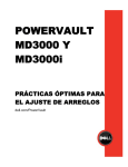
Reference Architecture for Active
System 800 with Microsoft Hyper-V
Release 1.0 for Dell PowerEdge 12th Generation Blade Servers,
Dell Force10 Switches, Dell EqualLogic iSCSI SAN, Microsoft
Windows Server 2012 with Hyper-V role and Dell Active System
Manager
Dell Global Solutions Engineering
Revision: A00
Reference Architecture for Active System 800m with Hyper-V:
This document is for informational purposes only and may contain typographical errors and
technical inaccuracies. The content is provided as is, without express or implied warranties of any
kind.
© 2013 Dell Inc. All rights reserved. Dell and its affiliates cannot be responsible for errors or omissions
in typography or photography. Dell, the Dell logo, Force10, EqualLogic, OpenManage, KACE and
PowerEdge are trademarks of Dell Inc. Intel and Xeon are registered trademarks of Intel Corporation in
the U.S. and other countries. Microsoft, Windows, Hyper-V, Active Directory, and Windows Server are
either trademarks or registered trademarks of Microsoft Corporation in the United States and/or other
countries. Other trademarks and trade names may be used in this document to refer to either the
entities claiming the marks and names or their products. Dell disclaims proprietary interest in the
marks and names of others.
March 2013 | Rev A00
Dell Inc.
ii
Reference Architecture for Active System 800m with Hyper-V:
Revision History
Revision
A00
Dell Inc.
Description
Initial Version
Date
March 2013
iii
Reference Architecture for Active System 800m with Hyper-V:
Table of Contents
1
Introduction ........................................................................................................... 1
2
Audience............................................................................................................... 1
3
Solution Overview ................................................................................................... 2
4
Design Principles ..................................................................................................... 6
5
Prerequisites and Datacenter Planning .......................................................................... 7
6
Architecture .......................................................................................................... 8
6.1
Dell Blade Network Architecture ......................................................................... 10
6.2
Server / Blade Network Connectivity .................................................................... 10
6.3
Server / Blade Storage Connectivity ..................................................................... 14
6.4
Server / Blade HA and Redundancy ...................................................................... 14
6.5
Storage Architecture ....................................................................................... 15
7
Management Infrastructure ...................................................................................... 18
7.1
Active System Manager ..................................................................................... 20
7.2
Microsoft Windows Server 2012 Built-In tools .......................................................... 20
7.3
Dell OpenManage Essentials ............................................................................... 22
7.4
Dell EqualLogic SAN HQ .................................................................................... 23
7.5
Out-of-band Management: CMC and iDRAC ............................................................. 24
7.6
System Center 2012 SP1 ................................................................................... 24
7.7
Dell System Center 2012 Integration .................................................................... 25
7.8
Out-Of-Band Management Connectivity ................................................................. 25
8
Scalability ........................................................................................................... 26
9
Delivery Model ...................................................................................................... 26
10
References....................................................................................................... 29
10.1
Dell PowerEdge Server Documentation and Hardware/Software Updates ........................ 29
10.2
Dell Force10 Switch Documentation and Firmware Updates ........................................ 29
10.3
Dell EqualLogic: ............................................................................................. 29
10.4
Dell Virtualization Documentation ....................................................................... 29
10.5
Microsoft® Hyper-V Documentation ..................................................................... 30
10.6
Microsoft® Management Software ....................................................................... 30
Figures
Figure 1: Overview of Dell Blade Servers, Dell Force10 network switches, Dell EqualLogic PS6110 Series
Storage, and Software .............................................................................................. 2
Figure 2: Converged Network Topology (Logical View) with optional 2nd Chassis ............................ 9
Dell Inc.
iv
Reference Architecture for Active System 800m with Hyper-V:
Figure 3: I/O Connectivity for M620 Blade Server ................................................................. 10
Figure 4: Converged Fabric Overview ................................................................................ 11
Figure 5: Converged Network configuration for Compute Dell PowerEdge M620 Blade Servers........... 12
Figure 6: Converged Network Configuration for Management of Dell PowerEdge R620 Servers .......... 13
Figure 7: Active System SAN Connectivity Overview .............................................................. 16
Figure 8: Management Architecture ................................................................................. 19
Figure 9: Manage Active System 800m with Server Manager .................................................... 21
Figure 10: Resources Measuring in PowerShell 3.0 ................................................................ 22
Figure 11: OME Dashboard ............................................................................................. 23
Figure 12: Connectivity of OOB management components. ..................................................... 26
Figure 13: Dell Active System 800m Rack and Component Overview .......................................... 27
Figure 14: Dell Active System 800m Maximum 2 Rack Component Overview ................................. 28
Tables
Table 1: Solution Components .......................................................................................... 3
Table 2: Traffic Description ........................................................................................... 13
Table 3: Sample VLAN and subnet configuration .................................................................. 14
Dell Inc.
v
Reference Architecture for Active System 800m with Hyper-V:
1 Introduction
Dell™ Active Infrastructure is a family of converged infrastructure solutions that combine servers,
storage, networking, and infrastructure management into an integrated and optimized system that
provides general purpose virtualized resource pools. Active Infrastructure leverages Dell innovations
including unified management with Active System Manager, converged LAN/SAN fabrics, and modular
server architecture for the ultimate converged infrastructure solution. Active Infrastructure helps IT
rapidly respond to dynamic business demands, maximize data center efficiency, and strengthen IT
service quality.
The Active System 800 solution, a member of Dell Active Infrastructure family, is a converged
infrastructure solution that has been designed and validated by Dell Engineering. It is available racked,
cabled, and delivered to your site to speed deployment. Dell Services deploys and configures the
system tailored for business needs and ready for integration into your datacenter. Active System 800 is
Dell’s first Active Infrastructure System to include Dell PowerEdge™ M620 Blades, ISCSI / 10GbE unified
fabric switching, Dell EqualLogic™ PS6110 Series 10GbE iSCSI storage, and Dell Active System Manager
to build private cloud solutions that address key needs of the mid to large data center. The backbone
of this solution is driven by features associated with a unified fabric consisting of both LAN and SAN
traffic on a consolidated network architecture via Data Center Bridging (DCB). The solution is offered
in configurations with either VMware® vSphere™ or Microsoft® Windows Server® 2012 with Hyper-V® role
enabled Hypervisors. The VMware vSphere solution is the Active System 800v and the Microsoft Hyper-V
solution is the Active System 800m. This document defines the reference architecture for Active
System 800m.
The Active System configurations vary in the number of Dell PowerEdge M620 blade servers and Dell
EqualLogic PS6110 Series storage arrays to meet virtualization resource needs.
2 Audience
This document provides an overview of the Active System 800 solution. Readers, including CTOs and IT
managers, can use this document to understand the overview and scope of the solution. IT
administrators and managers can use this document to understand the solution architecture.
Dell Inc.
1
Reference Architecture for Active System 800m with Hyper-V:
3 Solution Overview
This section provides a high-level product overview of the major components of the Active System 800
as illustrated in Figure 1. Readers can skip the sections of products with which they are familiar.
Figure 1: Overview of Dell Blade Servers, Dell Force10 network switches, Dell EqualLogic PS6110 Series
Storage, and Software
Microsoft Windows Server 2012
· Failover Clustering (High Availability and Live
Migration)
· Hyper-V Role Enabled
· Hyper-V and Cluster Management tools
Management Components
· Dell Active System Manager – Hardware
provisioning and management
· Dell EqualLogic SAN-HQ – SAN monitoring
· Dell OpenManage Essentials – Hardware
monitoring
· Optional System Center Virtual Machine Manager
– Hypervisor and VM management
Compute Cluster - Dell PowerEdge Blade Servers
· Energy efficient Dell PowerEdge M1000e enclosure
· Up to 32 Dell PowerEdge M620 blade servers
· CPU: 2x Intel® Xeon® 2.2GHz 95W 8C
· Memory: 128 GB (16x8GB) 1333 MHz RDIMMs
· NDC: BCM 57810-k (2x10GbE 10GBASE-KR)
· PowerEdge M I/O Aggregator
· IDRAC7 Enterprise
Management Cluster – Dell PowerEdge R620
· CPU: 2x Intel® Xeon 2.2GHz 95W 8C
· Memory: 128 GB (16x8GB) 1333 MHz RDIMMs
· NDC:
BCM 5720 (4x 1GbE RJ-45)
· NIC:
BCM 57810 PCI-e (2x 10GbE SFP+)
· iDRAC: iDRAC7 Enterprise
Dell Force10 S4810 48x 10GbE + 4x 40GbE Ports
· 2x S4810 High-density 48 port 10GbE switches for
converged LAN and SAN traffic
· 80GbE ISL between the switches
Dell Force10 S55 44x 1GbE + 4x SFP Ports
· 10/100/1000MbE Out of Band (OOB) Mgmt Traffic
Dell EqualLogic PS6110 Series iSCSI Storage
· 10GbE Controllers with up to 8 Arrays
· Default Solution
1x PS6100X per 4x hosts
with (24) 2.5" 900GB 10k
Table 1 below describes the key solution components and the roles served.
Dell Inc.
2
Reference Architecture for Active System 800m with Hyper-V:
Table 1: Solution Components
Component
Description
Role
Compute Cluster
PowerEdge M620 blade servers
running Windows Server 2012
Datacenter Edition with HyperV role enabled
Host highly-available virtual
machines (VMs)
Management Cluster
PowerEdge R620 servers running
Windows Server® 2012
Datacenter Edition with Hyper-V
role enabled.
Host management VMs: Dell
Active system Manager, optional
System Center Virtual Machine
Manager (VMM) 2012 SP1,
EqualLogic SAN HQ and Dell
OpenManage Essentials
Storage
Dell EqualLogic PS6110 Series
controllers with 24 bay 2.5‖ SAS
enclosures or 12 Bay 3.5‖ SAS
enclosures
Provide shared storage for the
Hyper-V clusters
Converged Network Switches
Two Force10 S4810 and Dell
PowerEdge M I/O Aggregator
modules for the blade chassis
Support VM, Live Migration,
Management, iSCSI and Cluster
traffic
OOB management Switch
One Force10 S55
Provide Management OOB
management connectivity
Microsoft Windows Server 2012: Microsoft® Windows Server® 2012 is Microsoft’s flagship server
operating system which provides the Hyper-V® virtualization platform. Hyper-V provides a
virtualization platform that can consolidate Windows® and Linux workloads enabling IT managers the
ability to more fully utilize their available hardware resources. The following Windows Server 2012
features are available in this solution.
Dell Active System Manager: Active System Manager sits at the center of Active System, and simplifies
infrastructure configuration, collapses management tools, and drives automation and consistency.
Through capabilities such as template-based provisioning, automated configuration, and infrastructure
lifecycle management, Active System Manager enables IT to respond rapidly to business needs,
maximize data center efficiency, and strengthen quality of IT service delivery.
The software enables a cloud like environment, and supports pre-built provisioning templates and
custom orchestrated workflows for a wide range of physical or virtual environments. Use and features
of the Dell Active System Manager will be described in more detail in subsequent sections of this
document. Additional detail can also be found on the Dell website at: Dell Active System Manager.
Note: Active System Manager offers limited functionality on Microsoft Hyper-V platforms with Active
System Manager version 7.0. The capabilities and benefits outlined above will be available on the
Microsoft Hyper-V platforms with the Active System Manager version 7.1 scheduled for release in mid
2013.
Dell OpenManage Essentials: The Dell OpenManage™ Essentials Console provides a single, easy-to-use,
one-to-many interface through which to manage resources in multivendor operating system and
hypervisor environments. It automates basic repetitive hardware management tasks — like discovery,
Dell Inc.
3
Reference Architecture for Active System 800m with Hyper-V:
monitoring and updates — for Dell servers, storage, and network systems. OME employs the embedded
management of Dell PowerEdge™ servers — Integrated Dell Remote Access Controller 7 (iDRAC7) with
Lifecycle Controller — to enable agent-free remote management and monitoring of server hardware
components like storage, networking, processors, and memory. For more information on Dell Enterprise
Management and OpenManage Essentials, see http://content.dell.com/us/en/enterprise/data-centersystem-management.
Dell EqualLogic SAN Headquarters (SAN HQ): SAN HQ provides in-depth reporting and analysis tools.
With the information you get from SAN HQ, you can better customize, protect, and optimize your
storage. Dell EqualLogic SAN HQ provides consolidated performance and robust event monitoring across
multiple Dell EqualLogic groups. If action is required, the Dell EqualLogic Group Manager can be
launched directly from SAN HQ giving you the ability to quickly adjust storage systems to meet business
needs. For more information about Dell EqualLogic storage and SAN HQ, see
http://www.dell.com/us/enterprise/p/equallogic-products.
Optional Microsoft System Center 2012 Service Pack 1: System Center 2012 is Microsoft’s systems
management platform which helps to monitor, manage, deploy, backup, and more. System Center 2012
Service Pack 1 (SP1) introduces support for Windows Server 2012, enabling you to take advantage of
Windows Server 2012’s new features in a managed environment. This solution utilizes either a customer
provided or a trial version of System Center 2012 SP1 and focuses on Virtual Machine Manager 2012.
Further information on all Microsoft System Center components can be found at
www.microsoft.com/systemcenter.
System Center 2012 Virtual Machine Manager (VMM): VMM is Microsoft’s centralized virtualization
manager. It provides the fundamental services for creating and managing virtual machines, optimizing
resources, and rapid deployment of virtualized infrastructure.
VMM 2012 Service Pack 1 supports the new features included in Windows Server 2012: network
virtualization, VHDX support, SMB 3.0 file share, and the enhancements on storage management, host
provisioning, and Live Migration.
Dell PowerEdge Blade Modular Enclosure: The Dell PowerEdge M1000e is a high-density, energyefficient blade chassis that supports up to sixteen half-height blade servers, or eight full-height blade
servers, and six I/O modules. A high-speed passive mid-plane connects the server modules to the I/O
modules, management, and power in the rear of the chassis. The enclosure includes a flip-out LCD
screen (for local configuration), six hot-pluggable/redundant power supplies, and nine hot-pluggable
N+1 redundant fan modules.
Blade Servers: The Dell PowerEdge M1000e Blade Server Chassis supports the Dell PowerEdge M620
blade servers based on Intel® Xeon® E5 series processors. Dell’s embedded management houses the
tools and enablement pieces for management directly on the server, allowing administrators to
perform a complete set of provisioning functions from a single, intuitive interface.
I/O Modules: The enclosure provides three redundant fabrics using six I/O modules. The modules can
be populated with Ethernet switches, Dell Power Edge M I/O Aggregator, Fibre Channel (FC), and
pass-through modules.
Chassis Management: The Dell PowerEdge M1000e has integrated management through a redundant
Chassis Management Controller (CMC) module for enclosure management and integrated keyboard,
video, and mouse (iKVM) modules.
Dell Inc.
4
Reference Architecture for Active System 800m with Hyper-V:
Embedded Management with Dell’s Lifecycle Controller: The Lifecycle Controller is the engine for
advanced embedded management and is delivered as part of iDRAC7 Enterprise in Dell PowerEdge 12th
generation blade servers. For more information on Dell Lifecycle Controllers and blade servers, see
http://content.dell.com/us/en/enterprise/dcsm-embedded-management and Dell.com/blades.
Dell PowerEdge M I/O Aggregator (I/OA): The Dell PowerEdge M I/O Aggregator is a flexible 1/10GbE
aggregation device that is automated and preconfigured for easy ―plug and play‖ deployment into
converged iSCSI and FCoE networks. The key feature of the PowerEdge M I/OA is that all VLANs are
allowed as a default setting. This allows the top-of-rack (ToR) managed switch to perform all VLAN
management related tasks. The external ports of the M I/OA are automatically all part of a single link
aggregation group (LAG), and thus there is no need for Spanning-Tree.
The M I/OA provides connectivity to the CNA/Network adapters internally and externally to upstream
network devices. Internally the M I/OA provides thirty-two (32) connections. The connections are 10
Gigabit Ethernet connections for basic Ethernet traffic, iSCSI storage traffic, or FCoE storage traffic. In
a typical PowerEdge M1000e configuration with 16 half-height blade server ports, 1-16 are used and 1732 are disabled. If quad port CNA/Network adapters or quarter-height blade servers are used, then
ports 17-32 are enabled.
The M I/OA includes two integrated 40Gb Ethernet ports on the base module. These ports are used in a
default configuration with a 4 X 10Gb breakout cable to provide four 10Gb links for network traffic.
Alternatively these ports can be used as 40Gb links for stacking. The M I/OA also supports three
different types of add-in expansion modules, which are called FlexIO Expansion modules. The modules
available are: 4-port 10Gbase-T FlexIO module, 4-port 10G SFP+ FlexIO module, and the 2-port 40G
QSFP+ FlexIO module. For more information on Dell PowerEdge M I/O Aggregator, see
http://www.dell.com/us/business/p/poweredge-m-io-aggregator/pd.
Dell Force10 S4810 Switches: The Dell Force10 S-Series S4810 is an ultra-low-latency 10/40 GbE topof-rack (ToR) switch. Leveraging a non-blocking, cut-through switching architecture, the Force10 S4810
switch delivers line-rate L2 and L3 forwarding capacity with ultra-low latency to maximize network
performance. The compact Force10 S4810 switch design provides 48 dual-speed 1/10 GbE (SFP+) ports
as well as four 40 GbE QSFP+ uplinks to conserve valuable rack space and simplify the migration to
40 Gbps in the data center core. Dell Force10 S4810 switch incorporates multiple architectural features
that optimize data center network flexibility, efficiency, and availability, including Force10’s stacking
technology, reversible front-to-back or back-to-front airflow for hot/cold aisle environments, and
redundant, hot-swappable power supplies and fans. For more information on Dell Force10 switches, see
Dell.com/force10.
Dell Force10 S55 Switches: Force10 S-Series S55 1/10 GbE Top-of-Rack switch leverages a nonblocking architecture that delivers line-rate, low-latency L2 and L3 switching to eliminate network
bottlenecks. The Force10 S55 switch design provides 48 GbE access ports with up to four modular
10GbE uplinks in 1-RU to conserve valuable rack space. The Force10 S55 switch incorporates multiple
architectural features including reversible front-to-back or back-to-front airflow for hot/cold aisle
environments and redundant, hot-swappable power supplies and fans. For more information on Dell
Force10 switches, see Dell.com/force10.
Dell EqualLogic PS6110 Series Storage: EqualLogic PS6110X 10GbE arrays include Dual 10GbE
controllers, high-performance 2.5‖ SAS HDDs Cache-to-flash memory de-staging and up to 21.6TB of
capacity in a 2U chassis.
Dell Inc.
5
Reference Architecture for Active System 800m with Hyper-V:
Management features include:
·
·
·
Group Manager, which integrates all management into one console for both file and block-storage
protocols
Dell EqualLogic Host Software that extends the functionality of the array-based software to enable
cooperation with the host
Host Integration Tools for Microsoft®, VMware® and Linux® products as well as Dell EqualLogic SAN
Headquarters (SAN HQ) management software
Contact your Dell sales representative for more information on Dell EqualLogic PS6110 Series storage
configurations and sizing guidelines. http://www.dell.com/us/enterprise/p/equallogic-ps6110series?~ck=anav
Dell PowerEdge R620 Management Server: The management server uses Intel® Xeon® E5-2600 series
processors in a 1U rack mount form factor. The server features two CPU sockets and 24 memory DIMM
slots supporting 2, 4, 8, 16 or 32GB DIMMs. For more information, see the Dell PowerEdge R620 guides
at Dell.com/PowerEdge.
4 Design Principles
The following principles are central to the design and architecture of Active System 800m Solution.
1. Converged Network: The infrastructure is designed to achieve end-to-end LAN and SAN
convergence.
2. Redundancy to minimize single point of failure: The system is designed to mitigate failure
points. NIC teaming and Multipath I/O (MPIO) are used to provide failover across the redundant
network interfaces. iSCSI storage redundancy is achieved with multiple ports and storage
controllers. For network traffic, NIC ports are teamed in such a way to distribute traffic across
separate ports. The solution also includes redundant power supplies connected to separate
Power Distribution Units (PDUs). The solution is further optimized to reduce components such
as NICs, cables, and IO Modules, then utilizes hypervisor-based high-availability to provide
virtual machine failover. Out-of-Band (OOB) Management is not architected with this level of
redundancy since mission critical workloads will continue to operate in the event of an OOB
management failure.
3. Management: Integrated management using Active System Manager, Dell OpenManage
Essentials, EqualLogic SAN HQ, and optional Microsoft System Center VMM 2012 SP1.
4. Flexible configurations: Dell Active System 800m is pre-configured to suit most customer
needs for a virtualized infrastructure. Each blade server is configured with sufficient CPU,
memory, and network adapters. Where desired, the solution also supports processor, memory,
and storage options. Additional options, such as wide or deep racks are also available.
5. Racked, Cabled, and Ready to be deployed: This Dell Active System is available to be racked,
cabled, and delivered to the customer site ready for deployment. Components are configured
and racked to optimize airflow and thermals. Based on customer needs, different rack sizes
and configurations are available to support various datacenter requirements.
Dell Inc.
6
Reference Architecture for Active System 800m with Hyper-V:
5 Prerequisites and Datacenter Planning
Power, Cooling, and Weight Considerations: Dell Active System 800m solution is configured with PDUs
to meet the power requirements of the components, as well as regional constraints. Power consumed,
cooling required, and information regarding rack weight are provided to enable customers to plan
appropriate power and cooling for the solution.
To support the architecture, the following components are required to be present in the customer
environment:
·
·
An existing Ethernet infrastructure with which to integrate. 10Gb or 40Gb Ethernet
infrastructure is recommended.
Additional components, such as Dell Force10 network cables and transceivers, are needed to
uplink the solution to the customer network. The necessary components depend upon customer
networking and uplink requirements.
·
Active Directory® Domain Services (AD DS) must be available on the network. The Hyper-V
hosts are joined to an existing or new domain. Cluster Services also require AD DS. Consult with
your Dell Sales and Services representatives for more details.
·
Domain Name System (DNS) must be available on the management network.
·
Database to support System Center 2012 VMM - For a list of supported databases refer to:
Requirements for System Center 2012 - Virtual Machine Manager.
·
o
If IT Administrators wish to install VMM on the Dell PowerEdge R620 Management Server
or as a VM, then a route must exist between the management server (physical or as a
VM) and the database used.
o
The database is presumed to have maintenance and backup configured as per the
business needs of the customer.
Sufficient power and cooling to support the solution must be present. Detailed power, weight,
and cooling requirements for the datacenter are defined in the Solution Specification Guide for
Active System 800 with Microsoft Hyper-V.
Dell Inc.
7
Reference Architecture for Active System 800m with Hyper-V:
6 Architecture
One of the key attributes of the Dell Active System 800m is the convergence of SAN and LAN over the
same network infrastructure. LAN and iSCSI SAN traffic share the same physical connections from
servers to storage. The converged network is designed using Data Center Bridging (DCB) (IEEE 802.1)
and Data Center Bridging Exchange (DCBX) (IEEE 802.1AB) technologies and features. The converged
network design drastically reduces cost and complexity by reducing the components and physical
connections and the associated efforts in deploying, configuring, and managing the infrastructure.
Data Center Bridging is a set of related standards to achieve enhanced Ethernet capabilities, especially
in datacenter environments, through converge network connectivity. The functionalities provided by
DCB and DCBX are:
·
Priority Flow Control (PFC): This capability provides zero packet loss under congestion by
providing a link-level flow control mechanism that can be controlled independently for each
priority.
·
Enhanced Transmission Selection (ETS): This capability provides a framework and mechanism
for bandwidth management for different traffic types by assigning bandwidth to different
frame priorities.
·
Data Center Bridging Exchange (DCBX): This functionality is used for conveying the
capabilities and configuration of the above features between neighbors to ensure consistent
configuration across the network.
Dell Force10 S4810 switches, Dell PowerEdge M I/O Aggregator modules, Broadcom 57810-k Dual port
10GbE KR Blade NDCs, and Dell EqualLogic PS6110 iSCSI SAN arrays enable Dell Active System 800m to
utilize these technologies, features, and capabilities to support converged network architecture.
This solution consists of a Dell PowerEdge M1000e chassis populated with Dell PowerEdge M620 blade
servers running Windows Server 2012 Data Center Edition. Figure 2 below depicts the high-level
reference architecture for the solution, including solution components and redundant connectivity for
each I/O fabric.
Dell Inc.
8
Reference Architecture for Active System 800m with Hyper-V:
Figure 2: Converged Network Topology (Logical View) with optional 2nd Chassis
Workload Virtual Machines
Force10 MXL 10/40GbE
S55
1
LNK
37-40
23
25
27
29
31
33
35
37
39
41
43
20
22
24
26
28
30
32
34
36
38
40
42 ACT
ter
Mas
USB-B
STACK ID
1
1
PSU
FAN
0
0
ALM SYS PSU
FAN
ACT
44
45
46
47
Ethernet
Core Network
USB-A
2 Gb VLT PEER LAG
Port-Channel
VLT PEER LAG
Port-channel 100
PSU
SYS
1
RS-232
Q SF P+
60
LNK
LNK
33-36
33-36
0
2
4
6
8
10
12
14
16
18
20
22
24
26
28
30
32
34
36
38
40
42
44
46
48
56
LNK
Ethernet
ACT
SFP+
ACT
ACT
146GB 15k
1
21
18
CONSOLE
SAS
1
146GB 15k
1
SAS
146GB 15k
SAS
1
SAS
1
146GB 15k
146GB 15k
SAS
146GB 15k
SAS
146GB 15k
SAS
146GB 15k
SAS
1
19
16
52
ACT
0
CONSOLE
1
17
14
ACT
0
15
12
37-40
0
13
10
1x 80 Gb
VLT PEER LAG per IOA
LNK
0
11
8
MA
STE
R
146GB 15k
0
9
6
SAS
146GB 15k
SAS
146GB 15k
146GB 15k
SAS
SAS
146GB 15k
SAS
146GB 15k
SAS
146GB 15k
SAS
146GB 15k
SAS
0
7
4
RS-232
S4810P
0
5
2
LNK
LNK/ SPD 0
41-48
41-48
0
3
FAN
1
Dell Force10 S55 Switch
1
49-56
49-56
Force10 MXL 10/40GbE
146GB 15k
SAS
146GB 15k
1
0
SAS
146GB 15k
146GB 15k
1
PowerEdge M I/O A
2 per M1000e
8
16
0
SAS
1
7
15
0
SAS
146GB 15k
1
6
14
0
SAS
146GB 15k
1
5
13
0
SAS
146GB 15k
SAS
146GB 15k
SAS
1
4
12
0
80Gb
VLT Interconnect
1
146GB 15k
SAS
146GB 15k
SAS
146GB 15k
SAS
SAS
146GB 15k
146GB 15k
SAS
146GB 15k
SAS
146GB 15k
SAS
146GB 15k
SAS
S4810P
1
RS-232
52
0
PSU
3
11
0
SYS
2
10
MA
STE
R
FAN
1
9
0
2
4
6
8
10
12
14
16
18
20
22
24
26
28
30
32
34
36
38
40
42
44
46
48
Q SF P+
60
56
LNK
Ethernet
ACT
SFP+
PowerEdge M1000e
1
9
0
2
10
3
11
0
0
7
15
0
0
146GB 15k
1
SAS
146GB 15k
1
Dell Force10 S4810 Switch
8
16
SAS
146GB 15k
146GB 15k
1
0
SAS
1
6
14
SAS
146GB 15k
1
0
SAS
146GB 15k
1
5
13
SAS
146GB 15k
SAS
146GB 15k
SAS
1
0
4
12
1
49-56
49-56
Force10 MXL 10/40GbE
Force10 MXL 10/40GbE
146GB 15k
0
0
41-48
41-48
LNK
LNK
37-40
37-40
ACT
ACT
33-36
33-36
1
1
1
1
1
ACT
ACT
1
LNK
LNK
146GB 15k
SAS
146GB 15k
SAS
146GB 15k
146GB 15k
SAS
SAS
146GB 15k
SAS
146GB 15k
SAS
146GB 15k
SAS
146GB 15k
SAS
CONSOLE
1
Dell EqualLogic 6110X Series
Arrays up to 8 max
Cabling shown is typical for each
SAS
146GB 15k
0
SAS
146GB 15k
146GB 15k
0
SAS
0
SAS
146GB 15k
0
SAS
146GB 15k
0
SAS
146GB 15k
SAS
146GB 15k
SAS
0
CONSOLE
1
146GB 15k
SAS
146GB 15k
SAS
146GB 15k
146GB 15k
SAS
SAS
146GB 15k
SAS
146GB 15k
SAS
146GB 15k
SAS
146GB 15k
SAS
PowerEdge M1000e
(8, 16, 24 or 32) x Dell PowerEdge
M620 Blade Servers in Up to 2 Dell
PowerEdge M1000e Chassis
Management Virtual Machines
(2) x PowerEdge
R620
One per server to each switch
LAN & iSCSI SAN
Dell Inc.
9
Reference Architecture for Active System 800m with Hyper-V:
6.1 Dell Blade Network Architecture
In this solution, the Chassis Fabric A contains Dell Force10 IO Aggregator modules and is used for
converged LAN and SAN traffic. Fabric B and Fabric C are not used.
M620 blade servers use the Broadcom 57810-k Dual port 10GbE KR Blade NDC to connect to the
Fabric A. Dell Force10 IO Aggregator modules uplink to Dell Force10 S4810 network switches providing
LAN AND SAN connectivity.
Figure 3 below illustrates how the fabrics are populated in a Dell blade server chassis and how the I/O
modules are utilized.
Figure 3: I/O Connectivity for M620 Blade Server
PowerEdge M620
Fabric C2
Unused
Mezz C
Unused
Fabric B2
Unused
Unused
Fabric A2
Dell PowerEdge M I/O
Aggregator
Mezz B
Fabric C1
Unused
Fabric B1
Unused
Fabric A1
Dell PowerEdge M I/O
Aggregator
NDC
Broadcom
57810-k
10Gb KR
6.2 Server / Blade Network Connectivity
The network traffic on each blade includes iSCSI as well as traffic for the parent partition (hypervisor),
Live Migration, cluster heartbeat, cluster shared volume, and child partitions (virtual machines).
A fault-tolerant network team is created by using:
·
·
·
Two 10 GbE NDC ports for each blade
A virtual switch is provisioned in Hyper-V
A virtual network adapter that is:
o Created
o Shared with the parent partition
o Segmented with VLANs
o Applied with bandwidth weighting
Dell Inc.
10
Reference Architecture for Active System 800m with Hyper-V:
Each Dell PowerEdge M620 blade server is configured with a Broadcom BCM57810 bNDC providing two
10GbE ports. These ports are connected to the Dell PowerEdge M I/O Aggregator in Fabric A. The
corresponding ports on A1 and A2 modules are connected with the two Dell Force10 S4810 switches
outside the blade chassis enclosure. Meanwhile, each PowerEdge R620 rack server is configured with a
Broadcom BCM57810 add-in NIC providing two 10Gb SPF+ ports, which are connected with the two
Force10 S4810 switches. The two Force10 S4810 switches are configured with a Virtual Line Trunk (VLT)
using two 40 Gbps QSFP+ ports in each switch providing an 80Gbps path for communication across the
switches. The solution network architecture is illustrated in Figure 4 below.
Figure 4: Converged Fabric Overview
M1000e Chassis
FAB A1
Dell
PowerEdge M
I/O
Aggregator
Fab A
Broadcom
57810
PowerEdge M620
Blade Server
80 Gb
VLT PEER LAG
80 Gb
VLT PEER LAG
Blade - 1
Dell Force10 S4810
Core Network
80Gb VLT
Interconnect
iSCSI SAN
Dell Force10 S4810
Blade 2-16 replicate the
connectivity of Blade-1
Equalogic PS6110
80 Gb
VLT PEER LAG
PowerEdge M620
Blade Server
FAB A2
Fab A
Broadcom
57810
Dell
PowerEdge M
I/O
Aggregator
Blade - 16
2 Gb
VLT PEER LAG
Dell Force10 S55
The second M1000e
replicates this connectivity.
CMC-2
Equalogic PS6110
Equalogic PS6110
CMC-1
Management Cluster
Equalogic PS6110
Broadcom
NIC
PowerEdge
PowerEdge
R620R620 Broadcom
NIC
Broadcom
10G SFP+
NIC
10G SFP+
10G SFP+
Up to 8 Arrays
10G SFP+
LAN & iSCSI SAN
10G SFP+
Management
10G SFP+
iDRAC
iDRAC
Management Uplink
The second R620 replicates this connectivity.
Figure 5 illustrates the converged network configuration and DCB settings for the PowerEdge M620
blade server. Figure 6 illustrates the configuration for the PowerEdge R620 management servers.
The VLAN IDs are assigned to the virtual network adapters assigned to the parent partition to segregate
the traffic on the host between the cluster, Live Migration, parent management, and other types of
traffic that are described in Table 2 below. The VLAN configuration used in the Dell Active System
configuration is listed in Table 3.
Dell Inc.
11
Reference Architecture for Active System 800m with Hyper-V:
Figure 5: Converged Network configuration for Compute Dell PowerEdge M620 Blade Servers
Management
VMn
BW Weight 5
Cluster / CSV
ConvergedNet Team
BW Weight 40
EQL Storage
with MPIO
VM2
(Switch Independent Hyper-V Port Load Balancing)
Live
Migration
VM1
BW Weight 20
Broadcom
57810 bNDC
iSCSI
0
NDIS
0
iSCSI
1
Single
Function
IOE Enabled
Single
Function
IOE Enabled
0
1
IO Aggregator
ETS 50% LAN
ETS 50% SAN + PFC
A1
IO Aggregator
DCB
Force10 S4810
10GbE w/ DCB
Dell Inc.
NDIS
1
A2
ETS 50% LAN
ETS 50% SAN + PFC
Force10 S4810
10GbE w/ DCB
12
Reference Architecture for Active System 800m with Hyper-V:
Figure 6: Converged Network Configuration for Management of Dell PowerEdge R620 Servers
Management
VMn
BW Weight 5
Cluster / CSV
ConvergedNet Team
BW Weight 40
EQL Storage
with MPIO
VM2
(Switch Independent Hyper-V Port Load Balancing)
Live
Migration
VM1
BW Weight 20
Add in CNA
Broadcom
57810 DP 10Gb
iSCSI
0
NDIS
0
iSCSI
1
NDIS
1
Single
Function
IOE Enabled
Single
Function
IOE Enabled
0
1
ETS 50% LAN
ETS 50% SAN + PFC
DCB
Force10 S4810
10GbE w/ DCB
ETS 50% LAN
ETS 50% SAN + PFC
Force10 S4810
10GbE w/ DCB
Table 2: Traffic Description
Traffic Type
Compute Node
Hypervisor
Compute Live
Migration
Use
Supports virtualization management traffic and communication between the
host servers in the cluster.
Supports migration of VMs between the host servers in the cluster.
Tenant VM
Supports communication between the VMs hosted on the cluster and external
systems.
Compute Cluster
Supports internal cluster network communication between the servers in the
cluster.
Out-of-Band
Management
iSCSI Data
Dell Inc.
Supports configuration and monitoring of the servers through the iDRAC
management interface, storage arrays, and network switches.
Supports iSCSI traffic between the servers and storage array(s). In addition,
traffic between the arrays is supported.
13
Reference Architecture for Active System 800m with Hyper-V:
Traffic Type
Management Node
Hypervisor
Management Cluster
Use
Supports virtualization management traffic and communication between the
management servers in the cluster.
Supports private cluster traffic for the management clusters.
Management Live
Migration
Supports migration of VMs between the management servers in the cluster.
Management Tenant
VM
Supports the virtual machine traffic for the management virtual machines.
Guest Clustering
Supports the private cluster communication required for SQL Clustering.
Table 3: Sample VLAN and subnet configuration
Traffic Type
Sample VLAN
Sample Subnet
Out-of-Band Management
24
10.110.4.0/24
Compute Node Management
20
10.110.0.0/24
Compute Live Migration
21
10.110.1.0/24
Compute Cluster Private
22
10.110.2.0/24
Management Tenant VM
23
10.110.3.0/24
iSCSI
25
10.110.5.0/24
Management Hypervisor
26
10.110.6.0/24
Management Cluster LM
27
10.110.7.0/24
Management Cluster Private
28
10.110.8.0/24
Guest Clustering (Microsoft FastTrack)
30
10.110.10.0/24
Tenant VM
32
10.110.12.0/22
6.3 Server / Blade Storage Connectivity
In the Dell Active System configuration, each PowerEdge M620 and R620 server uses an internal Dell
PERC H710 RAID controller and is connected to two SAS HDDs configured in a RAID-1. This RAID volume
hosts Windows Server 2012 for the hypervisor operating system.
Each server also includes Broadcom BCM 57810 Converged Network Adapter for attaching to SAN
volumes.
6.4 Server / Blade HA and Redundancy
The PowerEdge M620 blade chassis enclosure M1000e is designed with redundant power supplies and
redundant fans. Each PowerEdge M620 uses a Dell PERC H710 RAID controller and two hard drives
configured in a RAID-1, which hosts the parent operating system.
Dell Inc.
14
Reference Architecture for Active System 800m with Hyper-V:
The design of PowerEdge R620 servers includes high availability and redundant features such as
redundant fans and power supplies that are distributed to independent power sources. The servers also
use PERC H710 controllers with two hard disks configured with RAID-1 to prevent server crashes in the
event of single disk failures.
6.5 Storage Architecture
Dell EqualLogic PS6110 provides capabilities essential to the Active System 800m design, like 10Gb
connectivity, flexibility in configuring RAID arrays and creating volumes, thin provisioning, and storage
tiering.
6.5.1 EqualLogic Group and Pool Configuration
Each EqualLogic array (or member) is assigned to a particular group. Groups help in simplifying
management by enabling management of all members in a group from a single interface. Each group
contains one or more storage pools. Each pool must contain one or more members and each member is
associated with only one storage pool.
The iSCSI volumes are created at the pool level. In the case where multiple members are placed in a
single pool, the data is distributed amongst the members of the pool. With data being distributed over
a larger number of disks, the potential performance of iSCSI volumes within the pool is increased with
each member added.
6.5.1.1 Storage Network
Figure 7 below Illustrates the SAN Connectivity. Each Dell PowerEdge M620 blade server is configured
with a Broadcom BCM 57810 Converged Network Adapter Network Daughter Card. The BCM 57810
enumerates an iSCSI initiator device in addition to the standard LAN device, resulting in a converged
network fabric. Each port is wired across the Dell PowerEdge M1000e mid-plane to the Dell PowerEdge
M I/O Aggregators in Fabric A. These modules are trunked to the Dell Force10 S4810 ToR switches. The
10 GbE ports of Dell EqualLogic PS6110 Series are also connected to the S4810 ToR switches. For the
management servers, each PowerEdge R620 server is configured with a BCM 57810 Add-in PCI-E Card
and connected to the Force10 S4810 switches.
Both the blade servers and the rack servers utilize DCB to guarantee traffic flows from each node to
the SAN. The DCB configuration utilizes DCBX, PFC, and ETS. The DCB settings default to allow 50%
bandwidth for LAN traffic and 50% for SAN traffic. These ETS settings are configurable based upon
customer requirements. The PFC settings are configured to be lossless for the iSCSI queue.
Dell Inc.
15
Reference Architecture for Active System 800m with Hyper-V:
Figure 7: Active System SAN Connectivity Overview
Dell Inc.
16
Reference Architecture for Active System 800m with Hyper-V:
6.5.1.2 Performance
Dell EqualLogic PS6110 Series uses a redundant controller architecture with a single active 10GbE
front-end port per controller. To allow the network port to dedicate the 10GbE bandwidth to SAN
traffic, the 1GbE out-of-band port is used for configuration and performance monitoring.
6.5.1.3 Drive Types
The Dell EqualLogic PS6110 Series arrays use a high performance 10K RPM SAS drive in the default
configuration. This provides a balance of size and performance. The EqualLogic PS6110 is available with
drives in multiple speeds and sizes, including 10K RPM and 15K RPM SAS drives, 7.2K RPM NL-SAS drives,
and solid-state disks.
6.5.1.4 RAID Array Design
The storage array RAID configuration is highly dependent on the workload in your virtual environment.
The EqualLogic PS series storage arrays support RAID types: RAID 6, RAID 10, and RAID 50. The RAID
configuration will depend on workloads and customer requirements. In general, RAID 10 provides the
best performance at the expense of storage capacity, especially in random I/O situations. RAID 50
generally provides more usable storage, but has less performance than RAID 10. RAID 6 provides better
data protection than RAID 50.
For more information on configuring RAID in EqualLogic, refer to the white paper, How to Select the
Correct RAID for an EqualLogic SAN.
6.5.1.5 Storage Tiering
Tiering storage is the practice of physically partitioning data into multiple distinct classes based on
price, performance, or other attributes. Data may be dynamically moved among classes in a tiered
storage implementation based on access activity or other considerations.
This is normally achieved through a combination of varying types of disks which are used for different
data types. (i.e. Production, non-production, backups, etc.) Dell EqualLogic PS6110 Series dynamically
moves data to the optimal storage tier based on actual use. The most active blocks reside on
high-performance SSD and SAS drives, while infrequently accessed data migrates to lower-cost,
high-capacity SAS drives. The result is network storage that remains in tune with application needs.
6.5.1.6 High Availability
In order to maintain continuous connectivity to stored data from the server, the controllers of the
EqualLogic PS6110 have vertical port failover from active to standby controller. This port failover
mechanism allows a port to failover without having to failover the controller. This results in a lower
time that a controller is unavailable.
6.5.1.7 Multi-pathing
For Windows Server 2012, the native MPIO provides functionality for Dell EqualLogic. The EqualLogic
Host Integration Tools (HIT) kit provides enhanced load balancing and additional EqualLogic tools like
the PowerShell module for group management and the Auto-Snapshot Manager. The multi-pathing
solution uses the round-robin load balancing algorithm to utilize all available paths. Dell recommends
the EqualLogic Hit kit for its enhanced functionality and performance but either can be used.
Dell Inc.
17
Reference Architecture for Active System 800m with Hyper-V:
6.5.1.8 iSCSI Encryption and Authentication
Challenge Handshake Authentication Protocol (CHAP) is available for use on the EqualLogic PS6110
Series Storage Center. This feature allows hosts to authenticate to the EqualLogic PS6110 iSCSI target
prior to the target being available for use on the system.
6.5.1.9 Jumbo Frames
In the Dell Active System configuration, Jumbo Frames are enabled for all devices of the iSCSI SAN
fabric. This includes the server network interface ports, the network switch interfaces, and the
EqualLogic PS6110 Series interfaces.
6.5.1.10 Thin Provisioning
Particularly in virtualization environments, thin provisioning is a common practice. This allows for
efficient use of the available storage capacity. The volume and corresponding CSV may grow as
needed, typically in an automated fashion to ensure availability of the volume. However, as storage
becomes over-provisioned in this scenario, very careful management and capacity planning is critical.
EqualLogic PS6110 Series offers Thin Provisioning and eliminates pre-allocated but unused capacity.
7 Management Infrastructure
Within the Active System 800m solution, two Dell PowerEdge R620 servers and one Dell Force10 S55
1/10GbE Ethernet switch are used for the management infrastructure. The Force10 S55 switch is used
for out-of-band management connectivity for Dell CMC, Dell iDRAC, and the management ports on Dell
EqualLogic arrays. The management cluster infrastructure imitates the compute cluster in using
converged network infrastructure and configuration. The PowerEdge R620 servers are connected to the
Force10 S4810 switches using Broadcom 57810 Dual Port 10Gb network adapters. The management
servers are connected to the EqualLogic storage through the two Force10 S4810 switches.
Note that the EqualLogic storage is shared between the management cluster and the compute cluster.
The EqualLogic storage must be sized so that sufficient capacity and bandwidth are allocated for both
the management VMs and compute VMs.
The PowerEdge R620 servers run Windows Server 2012 with Hyper-V role enabled and are a part of the
unique management cluster.
The following management components are included in the Active System 800m:
·
Dell Active System Manager
·
Dell OpenManage Essentials (OME)
·
Dell EqualLogic SAN HeadQuarters (SAN HQ)
·
Optional: System Center 2012 SP1 Virtual Machine Manager
These components are installed in virtual machines in the management infrastructure as illustrated in
Figure 8 below.
Dell Inc.
18
Reference Architecture for Active System 800m with Hyper-V:
Figure 8: Management Architecture
System Center 2012 SP1
Virtual Machine Manager
Windows Server 2008 R2 VM
OpenManage Essentials &
EqualLogic SAN HQ
Dell Active System
Manager
Optional
SQL Server
System Center 2012 SP1
Operations Manager
Additional
System Center 2012 SP1
Components
Windows Server 2012 Datacenter Edition with
Hyper-V Role Enabled
Hyper-V Management Cluster
·
·
·
Core
Network
add-ons for
optional management
Dell OpenManage Server Management
Packs for SCOM
Dell ProPack 3.0
OpenManage Server Administrator
Two PowerEdge R620
hosting management
virtual machines
Solution Requirements
SQL Server
AD/DNS
The management infrastructure components are described in more detail in the following sections.
Dell Inc.
19
Reference Architecture for Active System 800m with Hyper-V:
7.1 Active System Manager
Active System Manager is an intelligent and intuitive converged infrastructure and workload manager.
Active System Manager leverages templates to automate infrastructure provisioning, on-boarding, and
re-configuration, which greatly simplifies and speeds up the process, and also significantly reduces
errors associated with manual configuration. The result is better infrastructure and workload quality
with fewer configuration errors that can be costly. Key features provided with Active System Manager:
·
Template-Based Provisioning — Streamline and standardize workload deployments through
centralized capture and application of best practices & operational steps
·
Infrastructure Lifecycle Mgmt — Discovery, inventory, configuration, provisioning, and ongoing
management of physical and virtual infrastructure
·
Resource Pooling & Dynamic Allocation — Create and manage physical and virtual resource
pools; efficiently schedule or allocate resources on-demand
·
End-To-End Automation — Multi-tier automation across physical (server, storage and network)
and virtual layers
·
Workflow Orchestration — Intelligent workflow orchestration engine for rapid physical and
virtual workload provisioning
·
Centralized Management — Intuitive centralized, role-based management and access through
self-service web portal
Note: Active System Manager offers limited functionality on Microsoft Hyper-V platforms with Active
System Manager version 7.0. The capabilities and benefits outlined above will be available on the
Microsoft Hyper-V platforms with the Active System Manager version 7.1 scheduled for release in mid
2013.
7.2 Microsoft Windows Server 2012 Built-In tools
Windows Server 2012 provides the following built-in new or updated management features and tools for
the virtualization solution:
·
Server Manager: Server Manager in Windows Server 2012 is re-designed as the primary
management console for all the systems including the remote servers in an environment. Server
Manager also manages the virtual machines and installed Windows roles on all managed
systems. It includes a role-based dashboard, which aggregates the data from managed servers.
It reports system health state and surfaces issues which require attention. The Server Manager
also creates customized groups for managed systems. Figure 9 illustrates an example of
managing a Dell Active System 800m with Server Manager.
Dell Inc.
20
Reference Architecture for Active System 800m with Hyper-V:
Figure 9: Manage Active System 800m with Server Manager
·
Hyper-V Manager: In Windows Server 2012, more than 160 PowerShell command-lets (cmdlets)
were added for Hyper-V. On the host management, Hyper-V Manager allows the configuring of
physical Graphics Processing Unit (GPU), Live Migrations, storage migration, and Hyper-V
replication. For virtual machine management, Hyper-V Manager includes more VM
configuration, such as FC Adapter, VM NUMA, NIC HW acceleration (VMQ, IPSec, SR-IOV) and
advanced features on MAC spoofing, DHCP guard, Router guard, port mirroring, and NIC
teaming. Also, VM management includes the support of Hyper-V Replica.
·
Failover Cluster Manager: With Failover Cluster Manager, the host configuration is validated
for a Failover Cluster. Multiple failover clusters and high-availability virtual machines are
created, configured and managed with the Failover Cluster Manager. In Windows Server 2012,
the Failover Cluster Manager adds support for storage space, Hyper-V Replica, and new types of
Live Migration. It also reports VM health states with more details, including Replication State,
and allows monitoring of the services running inside VMs.
·
PowerShell 3.0: Several significant features are included in PowerShell 3.0 which eases and
extends the management in the Windows-based environment. PowerShell 3.0 adds modules for
Hyper-V, storage, and network, etc. Hyper-V cmdlets help automate the Hyper-V management
tasks. With PowerShell 3.0, the resource utilization of VMs can be measured. This helps
dynamic chargeback (vs. flat upfront cost) and capacity planning. Figure 10 shows an example
of how to measure a VM with PowerShell 3.0.
Dell Inc.
21
Reference Architecture for Active System 800m with Hyper-V:
Figure 10: Resources Measuring in PowerShell 3.0
7.3 Dell OpenManage Essentials
Dell OpenManage Essentials (OME) is a system management console that provides simple, basic Dell
hardware management. Dell OME 1.1 manages the host running Windows Server 2012. It supports
agent-free hardware inventory and system update (e.g., BIOS, firmware) for the 11 th and 12th
generations of Dell PowerEdge servers. It also adds Dell SupportAssist extension for proactive ―phone
home‖ hardware issue resolution. Figure 11 shows the dashboard of Dell OME. Other features in Dell
OME 1.1 are:
·
·
·
·
·
·
·
·
·
·
·
·
Discover, Inventory, monitor health, and view logs of Dell clients (i.e., desktops, portables)
Discover, Inventory, and monitor health of Dell Force 10 Switches, Dell PDU and UPS devices
Discover and collect limited inventory Linux servers via Secure Shell (SSH)
Enhanced hardware inventory for ESXi servers with Dell OpenManage Server Administrator
(OMSA)
Alerts for hardware health status changes (not just when a hardware trap is sent)
Ability to forward alerts in original format to support tiered event management
A new command line interface (CLI) for automation of server discovery and grouping
Calendar style task schedule view
Group filtering on portal pages
More configurable portal pages
Grouped discovery ranges for common protocol settings
Custom URL launch points to allow user-defined right-click actions on devices
Dell Inc.
22
Reference Architecture for Active System 800m with Hyper-V:
For more information on OpenManage Essentials, see www.delltechcenter.com/ome.
Figure 11: OME Dashboard
Dell Lifecycle Controller: Helps to reduce operating costs by simplifying server deployment and
management. Key features include diagnostics, self-update (UEFI, Driver Pack update), firmware
updates (BIOS, NIC FW, RAID Controllers), and hardware configuration. Also, the integrated iDRAC
provides the mechanism for OME agentless management.
Dell OpenManage Server Administrator (OMSA): Dell OMSA provides a comprehensive, one-to-one
systems management solution. OMSA provides the mechanism for the agent-based management for Dell
OME. With agent-based management, OME can update the device drivers on the host in addition to
other management capabilities provided by the agentless management. For more information, see
http://www.delltechcenter.com/page/OpenManage+Server+Administrator+-+OMSA.
7.4 Dell EqualLogic SAN HQ
Dell EqualLogic SAN HQ provides comprehensive monitoring of performance and health statistics for
one or more EqualLogic PS Series groups. The tool is a client/server application that runs on a Microsoft
Windows server and uses SNMP to query the groups. Acting as a ―flight data recorder‖ on an aircraft,
SAN HQ collects data over time and stores it on the server for later retrieval and analysis. Client
systems connect to the server and format and display the data in the Dell SAN HQ GUI.
Dell Inc.
23
Reference Architecture for Active System 800m with Hyper-V:
Dell SAN HQ can:
·
Monitor one or more PS Series groups and store operational data for up to a year
·
Obtain a centralized view of the health and status of multiple groups
·
View IO rates, throughput, and latency for each volume, member, pool, or group
·
Allow the same performance data to be viewed by multiple clients simultaneously
·
Monitor and analyze capacity usage for groups
If action is required, launch the Dell EqualLogic Group Manager directly from SAN HQ to quickly adjust
storage systems to meet business needs.
7.5 Out-of-band Management: CMC and iDRAC
The CMC provides a single, secure interface to manage the inventory, configuration, monitoring, and
alerting for chassis components (iKVM, CMC), I/O modules, servers, and iDRAC. It also provides
excellent real-time power management, monitoring, and alerting capabilities. The Dell chassis provides
users with system-level power limiting, slot-based prioritization, and dynamic power engagement
functionalities. The iDRAC on each server provides the flexibility to remotely manage the server
through console redirection and Virtual CD-ROM/DVD/Floppy/Flash capabilities.
7.6 System Center 2012 SP1
System Center 2012 Virtual Machine Manager SP1. VMM 2012 is Microsoft’s virtualization management
platform. VMM 2012 provides in-depth management of both hypervisor and VMs. It provides a system
administrator the capability to create and deploy VM templates, manage library stores of VMs,
hardware profiles, and image files, and even manage VMware environments. VMM 2012 also provides
P2V (physical to virtual) functionality, thereby allowing a system administrator to convert physical
servers to virtual machines. VMM 2012 integrates with the hypervisor, VMs, and System Center
Operations Manager to provide a deep view of the system utilization.
VMM 2012 SP1 introduces the following new features:
·
Network Virtualization: Provides the ability to run multiple virtual network infrastructures,
even with overlapping IP addresses, on the same physical network. There are two mechanisms
to virtualize the IP address of a virtual machine: IP Rewrite or IP encapsulation.
·
VHDX Support: Supports converting from .vhd to vhdx. When creating a new virtual machine
with a blank virtual hard disk, VMM determines the VHD format based on the operating system
of the destination host.
·
Storage Management Enhancements: Supports the new Windows Standard-based Storage
Management service, which enables discovering storage by using multiple provider types. It
also supports thin provisioning of logical units, and the discovery of SAS storage.
·
Host Provisioning Enhancement: Support for performing Deep Discovery to retrieve more
detailed information about the physical computer hardware before deploying the OS.
Dell Inc.
24
Reference Architecture for Active System 800m with Hyper-V:
·
SMB 3.0 File Shares: Support for designating network file shares on Windows Server 2012
computers as the storage location for virtual machine files, such as configuration, virtual hard
disk files, and checkpoints.
·
Live Migration Enhancements: Supports performing simultaneous Live Migrations with options
like Live, Live VSM, and Live Storage.
7.7 Dell System Center 2012 Integration
Dell provides management packs for the optional System Center components to monitor servers,
storage, and networking components. These management packs allow System Center 2012 Operations
Manager (SCOM) to monitor, report, and take actions based upon alerts generated by the individual
components. Dell Server PRO Management Packs can be integrated with VMM to monitor Dell servers
and take remedial action when an inefficient system is identified.
Dell also provides integration tools for System Center Configuration Manager for the Lifecycle
Controller, providing a framework for bare-metal deployment of servers and operating systems. Dell
EqualLogic PS6110 Series also includes management tools for automating the deployment of virtual
machines with VMM 2012 SP1. These optional components are beyond the scope of this document.
Additional information can be obtained from your Dell Sales or Services representative.
7.8 Out-Of-Band Management Connectivity
The Dell Force10 S55 switch is used as a 1GbE out-of-band management switch. Each of the solution
components is connected to the Force10 S55 as shown in Figure 12. The Force10 S55 switch is uplinked
to each of the Force10 S4810 switches for core network connectivity.
Dell Inc.
25
Reference Architecture for Active System 800m with Hyper-V:
Figure 12: Connectivity of OOB management components.
8 4 2
8 4 2
PORT 2
1
Lnk Act
0
Lnk Act
Port
1
PORT 1
PowerEdge R620 Management Servers
1
2
1
2
1
2
1
2
3
750W
750W
750W
750W
4
PORT 2
8 4 2
8 4 2
1
Lnk Act
0
Lnk Act
Port
1
PORT 1
iDRAC
3
4
iDRAC
PSU
FAN
SYS
1
MAS
TER
Force10 S4810 Switches
S4810P
RS-232
52
0
2
4
6
8
10
12
14
16
18
20
22
24
26
28
30
32
34
36
38
40
42
44
46
Q SF P+
48
60
LNK
56
Ethernet
ACT
SFP+
Force10 S55 Switch
Uplink Ports
S55
1
3
5
7
9
11
13
15
17
19
21
23
25
27
29
31
33
35
37
39
41
43
2
4
6
8
10
12
14
16
18
20
22
24
26
28
30
32
34
36
38
40
42 ACT
ter
Mas
RS-232
USB-B
STACK ID
LNK
1
1
PSU
FAN
0
0
ALM SYS PSU
FAN
ACT
45
46
47
Ethernet
USB-A
PSU
44
RS-232
52
0
FAN
SYS
1
MAS
TER
LNK/ SPD 0
S4810P
2
4
6
8
10
12
14
16
18
20
22
24
26
28
30
32
34
36
38
40
42
44
46
48
Q SF P+
60
56
LNK
Ethernet
ACT
SFP+
CMC
CMC
CMC
CMC
CMC1
ETHERNET 0
MANAGEMENT
PPID
PWR
LINK
ERR
ACT
ACT
2
B1
C1
6
8
2
3
C2
4
9
5
Gb
1 Gb
2
Gb
1 Gb
2
B2
B1
C1
CMC2
2
4
3
5
7
1
A1
6
KVM
1
iKVM
3
5
7
CMC
CMC2
2
4
1
A1
KVM
1
iKVM
1 Gb
CMC
Gb
SERIAL PORT
CMC
CMC1
CONTROL MODULE 14
6
8
2
3
C2
4
9
5
Gb
1 Gb
2
CMC
EqualLogic PS 6110X Storage Arrays
Additional Arrays connected similarly
6
B2
A2
A2
STANDBY
ON/OFF
1
1
1
1
2
3
4
5
6
2
3
4
5
6
21
7
7
ETHERNET 0
MANAGEMENT
PPID
PWR
LINK
ERR
ACT
ACT
ETHERNET 0
MANAGEMENT
PPID
PWR
LINK
ERR
ACT
ACT
3
4
5
6
8
3
4
5
6
18
19
20
9
9
10
10
11
11
11
11
12
12
12
12
13
13
13
13
14
14
14
14
15
15
15
15
16
16
16
16
2
3
4
5
6
17
18
19
20
2
3
4
5
6
21
7
7
8
8
9
9
7
22
8
23
0
9
0
5
23
9
10
4
22
8
10
3
6
8
23
2
21
7
8
17
7
SERIAL PORT
STANDBY
ON/OFF
CONTROL MODULE 14
2
22
0
CONTROL MODULE 14
20
7
23
9
19
21
22
8
17
18
8/4Gbps FC SAN Module
20
10Gb Ethernet Pass Through
19
1
10Gb Ethernet Pass Through
6
17
18
8/4Gbps FC SAN Module
5
10Gb Ethernet Pass Through
4
8/4Gbps FC SAN Module
3
10Gb Ethernet Pass Through
2
1
1
2
SERIAL PORT
STANDBY
ON/OFF
10Gb Ethernet Pass Through
ERR
ACT
8/4Gbps FC SAN Module
PWR
ACT
10Gb Ethernet Pass Through
MANAGEMENT
PPID
LINK
10Gb Ethernet Pass Through
ETHERNET 0
10Gb Ethernet Pass Through
CONTROL MODULE 14
1
9
0
10
10
10
10
11
11
11
11
12
12
12
12
13
13
13
13
14
14
14
14
15
15
15
15
16
16
16
16
SERIAL PORT
STANDBY
ON/OFF
PowerEdge 1000e
Optional 2nd PowerEdge 1000e
OOB Management
8 Scalability
As workloads increase, the solution can be scaled to provide additional compute and storage resources
independently.
Scaling Compute and Network Resources: This solution is configured with two Dell Force10 S4810
network switches. Up to two Dell PowerEdge M1000e chassis can be added to the two Force10
switches.
Scaling Storage Resources: Dell EqualLogic PS6110 Series storage can be scaled seamlessly and
independent of the compute and network architectures. This design is currently limited to four
enclosures in the single rack configuration and eight enclosures in the two rack configurations.
9 Delivery Model
The Dell Active System 800m reference architecture can be purchased as a complete solution. This
solution is available to be racked, cabled, and delivered to the customer site to speed deployment.
Dell Services deploys and configures the solution tailored to the business needs of the customer and the
architecture is developed and validated by Dell Engineering. For more details or questions about the
delivery model, please consult with your Dell Sales representative.
Dell Inc.
26
Reference Architecture for Active System 800m with Hyper-V:
Figure 13 below shows the Dell Active System 800m solution with a single chassis. Figure 14 shows Dell
Active System 800m with two chassis and the maximum number of storage enclosures. Note that the
switches shown in the figures below are shown mounted forward for representation. In actual use,
ports face the back of the rack. PDUs shown are for illustration and vary by region or customer power
requirements. Additional PDUs are utilized within the rack.
Figure 13: Dell Active System 800m Rack and Component Overview
S55
7
9
11
13
15
17
19
21
23
25
27
29
31
33
35
37
39
41
43
4
6
8
10
12
14
16
18
20
22
24
26
28
30
32
34
36
38
40
42 ACT
1
1
er
Mast PSU FAN
USB-B
STACK ID
ALM SYS PSU
0
42
0
FAN
ACT
45
46
47
Ethernet
USB-A
SYS
44
1
RS-232
52
41
0
MAS
TER
5
2
RS-232
S4810P
PSU
3
LNK
LNK/ SPD 0
FAN
1
42
2
4
6
8
10
12
14
16
18
20
22
2
4
6
8
10
12
14
16
18
20
22
24
26
28
30
32
34
36
38
40
42
44
46
24
26
28
30
32
34
36
38
40
42
44
46
Q SF P+
48
60
56
41
LNK
Ethernet
ACT
1
MAS
TER
PSU
RS-232
52
0
FAN
SYS
SFP+
S4810P
40
48
Q SF P+
60
56
40
LNK
Ethernet
1x Dell Force10 S55 Switch
2x Dell Force10 S4810 Switch
(Rear face, Reverse fans)
ACT
SFP+
39
39
38
38
37
37
36
36
35
35
34
34
33
33
32
32
31
31
30
30
29
29
28
28
27
27
26
26
25
25
24
24
23
23
22
22
21
21
20
20
19
19
18
18
17
17
16
16
15
15
14
14
13
2x Dell PowerEdge R620
Management Cluster
1x KMM
4x Dell EqualLogic PS6110
Storage
13
1
9
2
10
3
11
4
12
5
13
6
14
7
15
8
16
12
12
0
0
0
0
0
0
0
0
1
1
1
1
1
1
1
1
11
11
10
10
09
09
08
08
0
0
0
0
0
0
0
0
07
07
06
06
1
1
1
1
1
1
1
1
05
05
04
Dell PowerEdge M1000e
Dell PowerEdge M620
Compute Cluster
FabA: 10GbE IOA
FabB: None
FabC: None
04
03
03
PowerEdge M1000e
02
02
J6
J5
J4
J3
J2
J1
J6
J5
J4
J3
J2
J1
01
01
2x G791N PDU (rear face)
(3 Phase, L15-30P, 3x C19)
The Dell Active System design shown in Figure 13 above accommodates up to 16 compute hosts in a one
rack configuration that also contains Dell EqualLogic PS6110 Series storage.
Dell Inc.
27
Reference Architecture for Active System 800m with Hyper-V:
Figure 14: Dell Active System 800m Maximum 2 Rack Component Overview
2x R620 Management Cluster
1x 17FP KMM
S55
1
3
5
7
9
11
13
15
17
19
21
23
25
27
29
31
33
35
37
39
41
43
2
4
6
8
10
12
14
16
18
20
22
24
26
28
30
32
34
36
38
40
42 ACT
er
Mast PSU1 FAN1
42
42
42
42
41
41
41
40
40
40
39
39
39
39
38
38
38
38
37
37
37
37
36
36
36
36
35
35
35
35
34
34
34
34
33
33
33
33
32
32
32
32
31
31
31
31
30
30
30
30
29
29
29
29
28
28
28
28
27
27
27
27
26
26
26
26
25
25
25
25
24
24
24
23
23
23
22
22
22
21
21
21
20
20
20
19
19
19
19
18
18
18
18
17
17
17
17
16
16
16
16
15
15
15
14
14
14
13
13
13
12
12
12
11
11
11
10
10
10
09
09
09
09
08
08
08
08
07
07
07
06
06
06
05
05
05
05
04
04
04
04
03
03
03
02
02
02
01
01
01
RS-232
USB-B
STACK ID
ALM SYS PSU0 FAN0
ACT
46
47
Ethernet
USB-A
RS-232
52
0
MAS
TER
45
1
PSU
44
SYS
S4810P
FAN
LNK
LNK/ SPD 0
41
2
4
6
8
10
12
14
16
18
20
22
24
26
28
30
32
34
36
38
40
42
44
46
Q SF P+
48
60
56
LNK
Ethernet
ACT
1
MAS
TER
RS-232
52
40
0
PSU
SYS
SFP+
S4810P
FAN
1x Force10 S55
2x Force10 S4810
(Rear face, Reverse fans)
2
4
6
8
10
12
14
16
18
20
22
24
26
28
30
32
34
36
38
40
42
44
46
48
Q SF P+
60
56
LNK
Ethernet
ACT
SFP+
1
9
2
10
3
11
4
12
5
13
6
14
7
15
8
16
24
0
0
0
0
0
0
0
0
23
22
1
M1000e
M620 Compute Cluster
FabA: 10GbE IOA
FabB: None
FabC: None
1
1
1
1
1
1
1
21
20
0
0
1
1
0
0
1
1
0
0
1
0
1
0
1
1
15
2x G791N PDU (rear face)
(3 Phase, L15-30P, 3x C19)
PowerEdge M1000e
14
J6
J5
J4
J3
J2
J1
J6
J5
J4
J3
J2
J1
13
1
9
2
10
3
11
4
12
5
13
6
14
7
15
8
16
12
0
0
0
0
0
0
0
0
11
10
1
M1000e
M620 Compute Cluster
FabA: 10GbE IOA
FabB: None
FabC: None
1
0
0
1
1
0
0
1
0
1
1
0
0
1
0
07
06
1
1
1
1
1
1
1
8x EqualLogic PS6110
Storage
1
03
PowerEdge M1000e
2x G791N PDU (rear face)
(3 Phase, L15-30P, 3x C19)
02
J6
J5
J4
J3
J2
J1
01
J6
J5
J4
J3
J2
J1
The Dell Active System design shown in Figure 14 accommodates up to 32 compute hosts along with
eight Dell EqualLogic PS6110 Series 2U or 4U storage enclosures in a two rack configuration.
Dell Inc.
28
Reference Architecture for Active System 800m with Hyper-V:
10 References
10.1 Dell PowerEdge Server Documentation and Hardware/Software Updates
For drivers and other downloads: Visit http://support.dell.com, click ―Start Here‖ for Enterprise IT,
―Select a product‖, then enter a server service tag or select the server model and operating system
version.
10.2 Dell Force10 Switch Documentation and Firmware Updates
Visit http://support.dell.com or click here for directions to sign onto your Force10 Online Support
account.
10.3 Dell EqualLogic:
·
Dell EqualLogic PS Series Architecture Whitepaper
http://www.dell.com/downloads/global/products/pvaul/en/dell_equallogic_architecture.pdf
·
Host Integration Tools for Windows
http://www.dell.com/downloads/global/products/pvaul/en/equallogic-host-software.pdf
·
PS Series Storage Arrays: Choosing a Member RAID Policy
http://www.equallogic.com/WorkArea/DownloadAsset.aspx?id=5231
·
Using Tiered Storage in a PS Series SAN
http://www.equallogic.com/resourcecenter/assetview.aspx?id=5239
·
Monitoring your PS Series SAN with SAN HQ
http://www.equallogic.com/resourcecenter/assetview.aspx?id=8749
10.4 Dell Virtualization Documentation
Microsoft® Windows Server® 2012 With Hyper-V™ for Dell™ PowerEdge™ Systems Important
Information Guide:
http://support.dell.com/support/topics/global.aspx/support/windows_server_support/windowsserver?c=us&cs=555&l=en&s=biz
Dell Inc.
29
Reference Architecture for Active System 800m with Hyper-V:
10.5 Microsoft® Hyper-V Documentation
Windows Server 2012
http://technet.microsoft.com/en-us/library/hh801901
Windows Server 2012 Hyper-V Whitepaper
http://download.microsoft.com/download/5/D/B/5DB1C7BF-6286-4431-A244438D4605DB1D/WS%202012%20White%20Paper_Hyper-V.pdf.
Failover Clusters in Windows Server 2012
http://technet.microsoft.com/en-us/library/hh831579
10.6 Microsoft® Management Software
Microsoft System Center 2012 SP1:
http://www.microsoft.com/en-us/server-cloud/system-center/datacenter-management.aspx
System Center 2012 Virtual Machine Manager Deployment:
http://technet.microsoft.com/en-us/library/gg610669
Dell Inc.
30