1
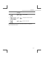
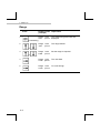
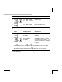
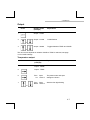
AquaCal 2000 PURE WATER CONDUCTIVITY METER OPERATION GUIDE Preface Preface Product warranty This guide, together with its associated software media and hardware, has a warranty against defects in materials and workmanship for a period of three years from the date of shipment. During this period LTH will, at its own discretion, either repair or replace products that prove to be defective. The associated software is provided 'As is' without warranty. Limitation of warranty The foregoing warranty does not cover damage caused by accidental misuse, abuse, neglect, misapplication or modification. No warranty of fitness for a particular purpose is offered. The user assumes the entire risk of using the product. Any liability of LTH is limited exclusively to the replacement of defective materials or workmanship. There are no user serviceable parts, including fuses etc., within the unit. Any attempt to dismantle the instrument will invalidate the warranty. Disclaimer LTH Electronics Ltd reserves the right to make changes to this manual or the instrument without notice, as part of our policy of continued developments and improvements. All care has been taken to ensure accuracy of information contained in this manual. However we cannot accept responsibility for any errors or damages resulting from errors or inaccuracies of information herein. Copyright and trademarks All rights reserved. Translations, reprinting or copying by any means of this manual, complete or in part or in any different form requires our explicit approval. AquaCal 2000 is a trademark of LTH Electronics Ltd. This guide was produced by Electrotech Services, 01245 471589 Third edition May 2014 Part number: 6129 LTH Electronics Ltd Chaul End Lane Luton Bedfordshire LU4 8EZ England Telephone Fax Email Web : : : : +44 (0)1582 593693 +44 (0)1582 598036 [email protected] www.lth.co.uk i Preface Standards Electromagnetic compatibility This instrument has been designed to comply with the standards and regulations called up by the European Directive on EMC Safety This instrument has been designed to comply with the IEC 348-1978 (BS 4743-1979) safety standard to Protection Class 1. Quality This instrument has been manufactured under the following quality standard: ISO 9001:2000. Certificate No: FM 13843 Note: The standards referred to in the design and construction of LTH products are those prevailing at the time of product launch. As the standards are altered from time to time, we reserve the right to include design modifications which are deemed necessary to comply with the new or revised regulations. ii Preface Contents 1 Introduction Traceable calibration AquaCal 2000 functions Analogue outputs Specifications 2 Installation Cells and sampling Connections and cabling D-connector Cell & Pt1000 D-connector - Battery charger and voltage outputs D-connector - Mounted on battery charger for voltage outputs 3 Operation Viewing the readings Viewing the AquaCal 2000 settings 4 Setting Up Security setting Range and units Units Range Temperature compensation Cell constant Output Temperature output Conductivity output Error messages, auto power off and input filter 1-1 1-1 1-1 1-3 1-4 2-1 2-1 2-1 2-6 2-6 2-6 3-1 3-1 3-2 4-1 4-1 4-2 4-2 4-4 4-5 4-6 4-7 4-7 4-9 4-10 iii Preface 5 Fault Finding 5-1 Introduction 5-1 Faults 5-2 Instrument appears dead 5-2 Instrument display appears to malfunction 5-2 Unable to program the instrument 5-2 Membrane switch panel appears to malfunction 5-2 Conductivity reading appears incorrect 5-2 Temperature reading appears incorrect 5-3 Voltage outputs appear incorrect or noisy 5-4 Error messages 5-4 General 5-5 System setup and operations 5-6 Conductivity/resistivity voltage output operations 5-6 Temperature voltage output settings 5-7 Analogue calibration operations 5-7 Floating-point mathematical routines 5-8 EEPROM checksums 5-9 6 Guarantee and service 6-1 Appendix A Cell positioning, flow rate and sampling A-1 Appendix BCalculating the temperature coefficient of a solution B-1 Index Quick Reference iv 1 Introduction 1 Introduction The AquaCal 2000 is a handheld microprocessor based unit which allows measurement to traceable standards. It measures the conductivity or resistivity of an aqueous solution and gives a direct digital readout. The instrument can be set to operate on a single fixed range or with full auto ranging. Two voltage outputs for remote monitoring or recording are available. Traceable calibration The AquaCal 2000 offers no user calibration: the instrument is factory calibrated to traceable standards. The cell provided is also calibrated to traceable standards and has a certified cell constant. The cell constant is the only user adjustable parameter and the user must ensure that the cell constant entered on the instrument matches that of the cell used. The cell constant programmed into the instrument must be changed if a different cell is to be used. AquaCal 2000 functions The front panel of the AquaCal 2000 provides a direct digital readout of the solution conductivity or resistivity and temperature. The instrument's operations are controlled with nine tactile membrane key switches. These switches select the information to be displayed, and allow the configuration parameters to be entered or edited. If desired, the parameters can be protected from casual tampering with a coded security setting. An input filter can be selected that averages measurements over a few seconds to provide a more stable display. An Auto Power Off facility can be set to turn off the unit if no keys are pressed for a preset period of time. In the event of an error, an error message may be displayed; this message display can be turned on or off, as required. 1-1 1 Introduction The following table summarises the functions provided by each key. In some cases, further functions can be reached by pressing . Key Description ON/OFF Switches the unit ON or OFF MEASURE Displays the conductivity/resistivity and temperature. RANGE/UNITS Displays the range and units and allows changes to be made. TEMP.COMP. Allows the temperature compensation to be turned on or off and the compensation slope to be set between 0.0 and 3.9%/°C. The base temperature can be set to either 20 or 25°C. CELL K Displays the cell constant and allows it to be changed. OUTPUT Displays the voltage output settings and allows them to be changed (if fitted). 1-2 1 Introduction The following functions are obtained by pressing two keys simultaneously. Keys Followed by Description Displays the error messages flag and allows them to be set IN (messages displayed) or OUT (not displayed). Displays and allows changing of the Auto Power Off time. Displays and allows selection/deselection of the input filter. Prompts the user to enter a security code; if code is entered correctly, user can lock or unlock instrument settings. Analogue outputs Two 0-1V DC analogue signals are provided. They share a common 0V but are electrically isolated from the cell, power supply and case. These outputs offer user scaleable offset and span up to a maximum of 10% of range. The voltage outputs allow remote monitoring for applications where additional readouts or recording of conductivity/resistivity and temperature are required. 1-3 1 Introduction Specifications Ranges of measurement Conductivity Resistivity 0 - 0.9999 µS/cm 0 - 999.9 K.cm 0 - 9.999 µS/cm 0 - 9.999 M.cm 0 - 99.99 µS/cm 0 - 99.99 M.cm Temperature -10.0 - +110.0°C 0 - 9.999 µS/m 0 - 99.99 µS/m 0 - 999.9 µS/m 0 - 9999 µS/m User selectable or full auto ranging Temperature compensated system accuracy, including linearity and repeatability 0.3% of range 0.3% of range 0.1°C Ambient temperature 0-50°C Ambient temperature variation 0.01% of range/°C (typical) Temperature compensation Fixed curve compensation for ultra pure water. Selectable slope of 0.0 to 3.9%/°C for the impurity contribution. Temperature compensation base Selectable 20°C or 25°C Display 16 x 2 character alphanumeric LCD Cell constant range Adjustable 0.01000 ±10% Operating frequency 70Hz Voltage outputs 2 off 0 - 1V DC isolated into a minimum load of 10K for conductivity or resistivity and temperature. User scaleable offset and span up to a maximum of 10% of range. 1-4 1 Introduction Battery type 4 x AA alkaline or NiCad rechargeable Battery life 40 hours continuous with alkaline batteries. NiCad batteries have typically half this life. Recharge time 24 hours from flat Low battery warning By a symbol on the display Auto power off Selectable, 1 minute to 40 hours, or disabled. Security Access code entered on the front panel. Electromagnetic compatibility Immunity IEC 801-2 to Level 4. IEC 801-3 to Level 3. IEC 801-4 to Level 3. IEC 801-5 (Draft) to Level 1. IEC 801-6 Pending. Environmental protection To IP65 Dimensions Instrument Carrying Case 195x101x44 mm 325x290x105 mm Weight 0.6 kg Less than 3 kg complete with cell, flow holder, battery charger and connection cables. 1-5 1 Introduction Cell type CMC26/001/PT43 Cell constant Nominally 0.01 supplied with traceable certification. Cell cable length Standard 2 metres. Maximum 5 metres Temperature sensor Pt1000 Battery Charger Supply 105-120 V or 200-250V AC 50-60 Hz (specify when ordering) Battery Charger output 12V DC, 100mA max This instrument complies with current European Directives 1-6 2 Installation 2 Installation Cells and sampling Refer to Appendix A for extracts from ASTM D5391-99 referring to cell positioning, flow rate and sampling. Although other cells can be used with the AquaCal 2000 instrument, the CMC26/001/PT43 allows measurement to traceable standards. To enable this, the cell is provided with a certified cell constant. The cell constant must be entered on the instrument to ensure accurate readings. A cell adapter cable to interface standard LTH C16 connectors is available. This will enable other LTH K=0.01 cells to be connected to the instrument: CMC11/001/PT43 ; CMC15/001/PT43; CMC24/001/PT43 ; CMC25/001/PT43 ; CMC34/001/PT43 When changing cells, it is imperative to enter the new cell constant on the instrument. A stainless steel flow chamber is available to allow inline measurement (Figure 2). Install the cell in the flow chamber and divert some or all of the flow through the chamber by connecting it to the inlet and outlet ports of the chamber. Always use the bottom port as the inlet to ensure that the flow fills the chamber. The flow chamber will stand on a flat surface (Figure 2). The user can also support it using the bracket supplied (Figure 3). Connections and cabling The CMC26/001/PT43 is fitted with a C16 connector and supplied with a seperate 2 metre cable and a 9 way D-connector. An adaptor cable is available to allow other K=0.01 cells fitted with LTH C16 plugs to be connected to the instrument. LTH can make up special cables to interface with other manufacturers' cells of constant K=0.01. Only cells fitted with a Pt1000 RTD can be tested in temperature compensated mode. A second D-connector is used for both the battery charger/power supply and the voltage outputs. If the voltage outputs are to be used, a connector and screened cable with four flying leads is provided. Figure 3 shows the pin connections on the connector and the wire colours of the cable supplied. 2-1 2 Installation Figure 5 shows the arrangement where a battery charger/power supply is used. In this case, the voltage output cable connects to the charger/supply unit instead of direct to the unit. Battery charger/power supply units are available for use on 110V AC and 230V AC; check the label on the unit before connecting it to the mains supply. Note: Hosetail connectors and sealing washers are available as an optional extra. These will fit tubing of 1/4"I.D. Figure 2 Flow chamber 2-2 2 Installation Figure 3 Suspended flow chamber 2-3 2 Installation Figure 4 Connections for battery operation See page 2-6 for wiring information. 2-4 2 Installation Figure 5 Connections for mains operation See page 2-6 for wiring information. 2-5 2 Installation D-connector Cell & Pt1000 1 C (centre electrode) 6 G (guard) 2 E (outer electrode) 7 Earth/shield 3 Earth/shield 8 T4 4 T1 9 T3 5 T2 T1 and T3 are connected to one side of the Pt1000. T2 and T4 are connected to the other side of the Pt1000. Note: the 4 wire connection to the RTD must be maintained for instrument accuracy. D D-connector - Battery charger and voltage outputs 1 2 + 0-1V DC signal output (cond/res) 67+ 0-1V DC signal output (temperature) 3 Earth/shield 8 Earth/shield 4 5 + 12V DC instrument supply 9 Earth/shield D-connector - Mounted on battery charger for voltage outputs 2-6 1 2 + 0-1V DC signal output (cond/res) 67+ 0-1V DC signal output (temperature) 3 Earth/shield 8 No connection 4 No connection 9 No connection 5 No connection 3 Operation 3 Operation This chapter explains the AquaCal 2000 display and the operational functions available from the front panel membrane switches. The AquaCal 2000 functions are selected using six operation keys in conjunction with the three modifier keys , and . The main functions are selected by pressing the corresponding key on its will scroll through other displays where own. Subsequent presses of applicable. Some functions are also available by pressing two keys simultaneously. When pressing a key, hold it down for about half a second or just long enough to produce the desired effect. Holding a key down for more than one second causes repeated action of the key function, where appropriate. Displayed figures shown in bold are flashing. Viewing the readings Pressing MEASURE will return the display to this. Note: The display always reverts to this display after 30 seconds, if no keys have been pressed. 3-1 3 Operation Viewing the AquaCal 2000 settings The following table shows the functions for viewing each of the AquaCal 2000 settings. In many cases, the operational key displays a sequence of settings which you step through by pressing To view Press . Display shows (example) Range and units Range Units 9.999 µS/cm Temperature Compensation TC In Cell Constant Cell Constant 0.01000 Conductivity Output Settings Output : COND Base 25°C Slope 2.0%/°C Output Range 9.999 µS/cm Zero 0.000 Temperature Output Settings Span 5.000µS/cm Output : COND Output : COND Output : TEMP 3-2 3 Operation To view Error Messages setting Press Display shows (example) Output : TEMP Zero 0.0 Span 100.0 C Errors In (error messages displayed) or Errors Out (not displayed). Auto off setting Auto off 0:10 Filter setting Filter In (measurements averaged) or Filter Out (not averaged) Security setting Yes Hh:Mm 0000 Out Enter Code If you enter the correct security code, display will change to Security Out or Security In. Parameter settings can be altered if the security setting is Out. Refer to Security setting on page 4-1 for more details. 3-3 3 Operation This page is intentionally left blank 3-4 4 Setting up 4 Setting Up This chapter describes the recommended procedure for setting up and configuring the AquaCal 2000. When pressing a key, hold it down for about half a second or just long enough to produce the desired effect. Holding a key down for more than one second causes repeated action of the key function, where appropriate. Displayed figures shown in bold are flashing. Security setting To prevent casual tampering with parameter settings, the instrument can be made secure. In order to lock or unlock the instrument, the user must enter a fixed security code (1582). The security setting can then be changed to In (locked) or Out (unlocked). To change the security setting: Press Display shows Explanation (example) 1 0000 Out Enter code The present setting of security is displayed in the top right corner 2 0000 Out Enter code The first digit flashes 1000 Out Enter code Increment or decrement the flashing digit. Set the first digit to '1'. 1000 Out Enter code The second digit will flash. or 3 or 4 Repeat steps 3 and 4 to set the remaining digits to '5', '8' and '2'. to confirm the displayed security code After entering the last digit, press '1582' (this is the LTH area telephone code). If the code is incorrectly entered, the display will revert to '0000'. 4-1 4 Setting up Press Display shows Explanation (example) 5 Security Out Display change to allow user to change setting 6 Security Out The setting flashes Security In Change the setting Security In Enter the setting or 7 or 8 Press MEASURE to leave the security screen. Range and units The ranges that are available (see page 1-4) depend on the units selected. Therefore if a change of units is required, these should be set first. After setting the units, the range is automatically set to Auto. You can then select the required fixed range from those available for the selected units. Units Press Display shows Explanation (example) 1 Range Units Auto µS/cm The present range and units are displayed 2 Range Units µS/cm Auto The range flashes or 4-2 4 Setting up Press Display shows Explanation (example) 3 Range Units Auto µS/cm 4 Range Units Change the units as required Auto M.cm The units flash or 5 Range Units Enter the new units Auto M.cm If a range change is now required, follow the procedure for changing the range, omitting the first step. 4-3 4 Setting up Range Press Display shows Explanation (example) 1 Range Units Auto µS/cm The present range and units are displayed Range Units µS/cm Auto The range flashes Range Units µS/cm 9.999 Set the range as required 4 Range Units 9.999 µS/cm The units flash 5 Range Units 9.999 µS/cm To scroll through (If necessary) 2 or 3 or 4-4 4 Setting up Temperature compensation Press 1 Note: Display shows (example) Explanation TC In The present settings are displayed. Base Slope 25°C 2.0%/°C If TC is Out, Base and Slope are not displayed as they are not relevant. 2 TC In Base Slope 25°C 2.0%/°C The T.C. In (or Out) flashes or or Press 3 to change the T.C. status. TC In Base Slope 25°C 2.0%/°C Enter T.C. status and advance to base temperature If Out is selected, the display clears and no further entry is necessary. If In is selected: TC In Base Slope 20°C 2.0%/°C Select 20 or 25°C 5 TC In Base Slope 20°C 2.0%/°C Enter the base temperature and advance to slope value 6 TC In Base Slope 20°C 1.0%/°C Set the first digit of the slope as required TC In Base Slope 20°C 1.0%/°C Advance to the next digit 4 or or 7 4-5 4 Setting up Press 8 Display shows Explanation TC In Base Slope 20°C 1.9%/°C Set the digit TC In Base Slope 20°C 1.9%/°C Enter the slope value or 9 Cell constant Press Display shows Explanation 1 Cell Constant 0.01000 The present setting is displayed 2 Cell Constant 0.01000 The digit '1' flashes. This digit can only be set as either 1 or 0, as the cell constant can only be set between 0.00900 and 0.01100 or Use in conjunction with and When the last digit is flashing, press to set the value of the cell constant. to enter the new cell constant. The unit will ignore an illegal cell constant entry; it will instead use and display the last legal entry. 4-6 4 Setting up Output Press Display shows (example) Explanation 1 Output : COND 2 Output : COND COND flashes Output : TEMP Toggles between TEMP and COND or 3 or The next screen depends on whether COND or TEMP is selected, see page 4-9 for COND settings. Temperature output Press Display shows (example) Explanation 4 Output : TEMP TEMP flashes 5 Output : TEMP 6 Zero 0.0 7 Zero Span 000.0 100.0°C or Span 100.0°C The present zero and span settings are shown Start the first digit flashing 4-7 4 Setting up Press Display shows (example) 8 Explanation Increment or decrement the flashing digit or 9 Enter the flashing digit and move to the next digit Repeat steps 8 and 9 for each digit of both zero and span values. When the last digit is flashing, press 4-8 to confirm the settings. 4 Setting up Conductivity output Press Display shows (example) Explanation 4 Output : COND COND flashes 5 Output : COND 6 Output Range 9.999 µS/cm 7 Output Range 9.999 µS/cm The present output range is displayed or Note: The conductivity output units must be the same as the measurement units. If the measurement units have been changed, the old units will or is pressed to flash the range. At this be displayed, until time, the units will automatically align with the measurement units. Note: Auto ranging is not available on the output range setting. 8 Output Range 99.99 µS/cm 9 Zero Span 00.00 99.99 µS/cm The present settings are displayed To make alterations here, follow the procedure shown previously for adjusting the temperature output zero and span. 4-9 4 Setting up Error messages, auto power off and input filter Note: Some of the following steps should be omitted where changes are not required to all of the settings. Press Display shows (example) Explanation 1 Errors In Error messages will be displayed. 2 Errors In In flashing. Errors Out Select In or Out to display error messages (In) or not (Out). 4 Errors Out Enter setting 5 Auto off Yes 00:10 Hh:Mm Instrument will switch off after 10 minutes if no key has been pressed. 6 Auto off Yes 00:10 Hh:Mm Yes flashing. Toggle between Yes for automatic power off or No for none. Auto off Yes Confirm Yes/No selection. If you select No, the time will not be adjustable. or 3 or or 7 00:10 Hh:Mm 8 Auto off Yes 10:10 Hh:Mm Increment/decrement flashing digit. Auto off Yes 10:10 Hh:Mm Confirm digit selection. or 9 4-10 4 Setting up Press Display shows (example) Explanation Repeat steps 8 and 9 for each digit. The data is entered into memory during step 9 for the last digit. 10 To confirm Auto Off time. Instead of displaying each measurement as it is made, the Filter option displays the average of the last 16 measurements, thus reducing any fluctuations due to variations of the water conductivity at the sample point. The disadvantage of using the filter is that it introduces a fairly long delay when the instrument is exposed to a large and rapid change in conductivity. 11 Filter Out Filter not operating 12 Filter Out In/Out flashing. Toggle the setting to In (filter operating) or Out (filter not operating). or 13 Filter In or 14 Filter In Enter setting. Press MEASURE to return to main display. 4-11 4 Setting up This page is intentionally left blank 4-12 5 Fault finding 5 Fault Finding Introduction Note: THERE ARE NO USER SERVICEABLE PARTS INSIDE THE UNIT. A set of error messages has been built into the system to aid fault finding and diagnosis. If one of these messages is being displayed, refer to the table at the end of this section; this lists some possible causes and suggested actions. Ensure that the error messages have not been turned off; refer to the final part of Section 4, Error messages, auto power off and input filter. Fault finding hints are included below. If the fault has not been cleared after these checks have been carried out, contact LTH. Please have as much of the following information available as possible in any communication with LTH, to enable a quick repair or diagnosis of the problem to be made: Serial number of the instrument. The approximate date of purchase. Details of the programme settings and application. Software issue number (shown during the power up initialisation routine). Electrical environment and supply details. Circumstances under which failure occurred. The nature of the fault or faults. Any error messages that were displayed. The sensor type, cable length and serial number. Voltage output monitoring and cable lengths. 6-1 5 Fault finding Faults Instrument appears dead 1. Check that batteries are fitted and have correct polarity. Try using the battery charger to power the instrument. 2. Remove batteries for a few seconds, then replace them and switch on. This checks that a programme latch-up has not occurred. Instrument display appears to malfunction 1. Switch off (or remove batteries) and on again. Check that the display shows full blocks for five seconds, followed by the Software Issue number. 2. If the fault remains, repeat the operation a couple of times. Unable to program the instrument Check that the software security switch is set to Out. Membrane switch panel appears to malfunction 1. Check that the software security switch is set to Out. 2. Check that the tactile membrane key switches are 'popping'. Conductivity reading appears incorrect Refer to Appendix A. 1. Low conductivity due to incomplete immersion of cell electrodes or air bubbles within the cell. 2. High conductivity readings caused by a short circuit within the cell moulding. The cell should be checked, when dry, with an ohmmeter. The resistance should be greater than 50M. See 9 way D-connector details in Section 2. 3. High conductivity can be caused by accumulation of trapped air or gas coming out of solution. Check that no "air traps" exist in the cell installation. 4. High conductivity readings caused by leakage of solution into the terminal housing. This indicates that the cell material has been fractured and the cell must be replaced. 5. Firstly check that the temperature reading is correct, otherwise the temperature compensation software will cause false or erratic readings. 5-2 5 Fault finding Temporarily switching out the temperature compensation can help to show if this is the cause of the problem. 6. If another sensor is available, this can be used to determine whether the fault lies with the instrument or the sensor. 7. Check that the temperature compensation base temperature is set correctly to 20°C or 25°C, as required. 8. Check that the sensor cable is not damaged or broken and that the screen does not make contact with any other terminals or metal work. Under no circumstances should it be connected to the ground. 9. Check that the sensor cable is sufficiently distant from power cables or electrical noise sources. 10. Check that the correct cell constant has been selected. 11. Check that the correct range has been selected. 12. Check that the temperature compensation has been switched in if required, and that the temperature slope has been set to a sensible value for the application. 13. Check that the sensor cable is under the maximum specified length (25m). Temperature reading appears incorrect 1. Check that the sensor is at the temperature indicated. Allow a minute or two for the sensor to stabilise. 2. Check the solution temperature by an independant method, eg. a mercury and glass thermometer. 3. If another sensor is available, this can be used to determine whether the fault lies with the instrument or the sensor. A few minutes should be allowed for stabilisation of the temperature element. 4 Measure the resistance of the temperature sensor (see 9 way Dconnector details in Section 2). It should be about 1000 at 0°C to 1385 at 100°C. 5. Check that a wire has not become loose in a junction box or in the terminal block. 6. Check that a full 4 wire method has been used to connect the Pt1000 to the instrument. (LTH cables are always configured to this method). 5-3 5 Fault finding Voltage outputs appear incorrect or noisy 1. Check that the load resistance is not less than 10K. 2. Check that the plug and cable is not broken or damaged (see 9 way Dconnector details in Section 2). 3. If a junction box is used, check that it has been wired correctly. 4. Check that the cable is not too close to power cables, contactors, motors etc. 5. Check that screened cable or twisted-pair wiring has been used for the output connections in electrically-noisy environments. 6. Check that the voltage output operating ranges have been set up correctly. Error messages Error messages are generated when a system fault occurs, when the instrument is incorrectly programmed by the user, or when the normal limits of operation are exceeded. The messages will show in the bottom right hand corner of the main display, provided they have not been turned off (see page 4-10). Normal operation of the instrument will continue in most cases. If more than one error occurs at any time, the unit will display the error message with the lowest numerical value. When an error message is displayed it is therefore possible for other errors to have occurred. Although the instrument is capable of operating with some (for example Er25), it is not advisable to let this situation persist as it may hide other more important and harmful messages. 5-4 5 Fault finding General Error Description Action/Explanation Main input saturation. Solution conductivity/resistivity is too high, for the selected range, or is at an extreme of temperature. See the appendices for details. Main input saturation. Solution conductivity/resistivity is too low, for the selected range, or is at an extreme of temperature. See the appendices for details. Temperature sensor open circuit or above 110°C. Check probe temperature, connections and sensor Temperature sensor short circuit or below -10°C. Check probe temperature, connections and sensor. Main measurement overrange. . Can also be displayed As for during Auto range changing, as a result of a large change in measurement. This will clear in a short period of time. Main measurement underrange. As for Excessive system Check temperature compensation slope temperature compensation. and solution temperature. See the appendices for details. Reserved for future expansion. Reserved for future expansion. 5-5 5 Fault finding System setup and operations Error Description Action/Explanation Instrument range corrupted. Check units and operating range. Instrument units corrupted. Check units and operating range. Conductivity/resistivity voltage output operations This is only available when the Output option is fitted. Error Description Action/Explanation Measurement units do not match output units. Set output range, zero and span. Voltage output zero greater Ensure zero is less than span, and than or equal to voltage span is less than instrument range fsd. output span (all ranges). Voltage output span less than 10% of (fixed range) fsd. Increase voltage output span or decrease instrument range. Conductivity/resistivity less Set zero lower if required, but the than the programmed instrument can operate in this condition voltage output minimum. * if necessary. Conductivity/resistivity Set span higher if required, but the greater than the instrument can operate in this condition programmed voltage output if necessary. maximum. * * The unit may be used in situations where the conductivity/resistivity periodically goes outside the limits. 5-6 5 Fault finding Temperature voltage output settings This is only applicable when the output option is fitted. Error Description Action/Explanation Voltage output zero setting is greater than span setting. Check zero and span settings. Voltage output span is less As for than 10% of full-scale. Temperature is less than voltage output zero. As for Temperature is greater than As for voltage output span. Analogue calibration operations Error Description Action/Explanation Conductivity/resistivity zero Fault in calibration data. Return to at limit. factory or call service engineer. Conductivity/resistivity span As for at limit. Temperature zero at limit. As for Temperature span at limit. As for 5-7 5 Fault finding Floating-point mathematical routines Error Description Action/Explanation Overflow error. Internal maths computation fault. Check operating conditions first. Underflow error. Internal maths computation fault. Check operating conditions first. Divide by 0 error. Internal maths computation fault. Check operating conditions first. Too large for conversion error. Internal maths computation fault. Check operating conditions first. Too small for conversion error. Internal maths computation fault. Check operating conditions first. EEPROM checksums Error Description Action/Explanation Checksum A error detected. Data corrupted. Check range, units, cell constant, temperature compensation settings, auto time, output range and units, security, filter setting and error message setting. Checksum B error detected. Data corrupted. Check output zero and span settings. Checksum C error detected. Fault in calibration data. Return to factory or call service engineer. Checksum D error detected. As for Memory write out of range. As for 5-8 6 Guarantee and service 6 Guarantee and service Products manufactured by LTH Electronics Ltd are guaranteed against faulty workmanship and materials for a period of three years from the date of despatch, except for finished goods not of LTH manufacture, which are subject to a separate agreement. All cells made by LTH are thoroughly tested to their published specification before despatch. As LTH have no control over the conditions in which their cells are used, no further guarantee is given, although any complaints concerning their operation will be carefully investigated. Goods for attention under guarantee (unless otherwise agreed) must be returned to the factory carriage paid and, if accepted for free repair, will be returned to the customer's address free of charge. Arrangements can also be made for repair on site, in which case a charge may be made for the engineer's time and expenses. If any services other than those covered by the guarantee are required, please contact LTH direct. Note: Overseas users should contact their LTH agent. Special arrangements will be made in individual cases for goods returned from overseas. 6-1 6 Guarantee and service This page is intentionally left blank 6-2 App A Cell positioning Appendix A Cell positioning, flow rate and sampling This is a summary of ASTM D5391-99, combined with LTH application notes. Pure water conductivity or resistivity must be measured with a cell and temperature sensor in a flowing, closed system to prevent trace contamination from wetted surfaces and from the atmosphere. Specialised temperature compensation can be used to correct the measurement to a reference temperature of 20 or 25°C taking into account the temperature effects on the ionisation of water, the contaminates and interactions between the two. The cell constant for the precision cell has been determined with a secondary standard cell that has a cell constant determined by ASTM D1125-95. Conductivity or resistivity can be used for detecting trace amounts of ionic contaminates in water. It is the primary means of monitoring the performance of demineralisation and other high purity water treatment operations. It is used to detect ionic contamination in boiler waters, microelectronics rinse waters, pharmaceutical process waters and to monitor and control the level of boiler and power plant cycle treatment chemicals. Exposure of the sample to atmosphere will cause changes in the conductivity/resistivity due to loss or gain of dissolved ionisable gases. CO2 can reach an equilibrium concentration in water of about 1 mg/l and add up to 1 µS/cm to the conductivity due to the formation of carbonic acid. This process is quite fast, depending upon conditions. Cell, flow chamber and sample line surfaces will slowly leach trace ionic contaminates, evidenced by increasing conductivity readings with very low or zero flow rate. There must be sufficient flow to keep these contaminates from accumulating to the point where they can significantly affect the measurement. The high and convoluted surface of platinised cells precludes their use for high purity measurements for this reason. Samples containing dissolved gases must have sufficient flow through the cell so that bubbles cannot accumulate and occupy sample volume within the cell, causing low conductivity (high resistivity) readings. High purity conductivity measurement must not be made on a sample downstream of pH sensors due to the possible contamination of the sample with traces of reference electrolyte salts. Use a dedicated sample line or place the conductivity cell up stream from the pH sensors. A-1 App A Cell positioning Conductivity cells mounted downstream from ion exchangers are vulnerable to catching ion exchange resin particles between the cell electrodes. Resin particles are sufficiently conductive to short circuit the cell and cause high off scale conductivity or extremely low resistivity readings. Resin retainers must be effective and the cell must be installed so that it is accessible for cleaning. If this is a problem with the CMC26/001/PT43 cell use the CMC34/001/PT43 which has wider spaced electrodes of greater than 1.5mm. This has been found to be less likely to trap such particles. Conductivity cells if subjected to demineraliser regeneration reagents require excessive rinse time to obtain satisfactory results, therefore, locate the cell where it will be isolated during regeneration. The cell should not be used to measure high ionic content samples of greater than 20 µS/cm (less than 0.05 M.cm) since it can retain ionic contaminates and require excessive rinse down time for valid measurements. Cell extension cable can be added to the standard length of 2 metres up to a maximum of 5 metres. The instrument incorporates an electronic guard to minimise the effect of cable capacitance and a 4 wire temperature measurement system to allow accurate measurements with long cell connection cables. LTH 54G cable must be used to ensure correct operation. The cell must be located in an active flowing part of the piping. Stagnant areas or dead legs must be avoided to ensure a representative sample and prevent any bubbles from adhering to the cell surfaces. Sample lines must be designed to maintain sample integrity. Do not expose the sample to atmosphere to prevent absorption or loss of gases, particularly CO2 which will affect conductivity. The sample should be continuous at a stable flow rate of at least 100ml/min and should be maintained to enable sample line wetted surfaces to reach equilibrium with sample conditions. Do not make measurements following changes to sample flow rate for the period of time required to recover from transient effects on the particular sampling system. A-2 App B Calculating temp. coefficient Appendix B Calculating the temperature coefficient of a solution If the temperature coefficient of the solution being monitored is not known, the AquaCal 2000 can be used to determine that coefficient. You should set the AquaCal 2000 to auto ranging, with the temperature compensation IN and the temperature coefficient to 0.0%. The following measurements should be done as near to the normal operating point as practical, between 5C and 70C for the highest accuracy. Ensure that the cell is in-line with a flowing sample. Allow the temperature sensor sufficient time to stabilise, approximately two or three minutes, and then record both the temperature and conductivity readings. Raise the solution temperature by at least 10C and again record the temperature and conductivity readings. Using the following equation, the temperature compensation slope can be calculated in percentage terms: = (Gx-Gy) x 100% . Gy(Tx-25) - Gx(Ty-25) Note: If base temperature is set to 20C, then replace 25 with 20 in the above equation. Term Description Gx Conductivity in S/cm at temperature Tx Gy Conductivity in S/cm at temperature Ty Note: One of these measurements can be done at ambient temperature. Programme this compensation slope value into the AquaCal 2000. The temperature compensation is now set up for normal operation. If it is difficult or impossible to evaluate the temperature compensation slope using this method, a 2.0%/C setting will generally give a good first approximation until the true value can be determined by independent means. B-1 App B Calculating temp. coefficient This page is intentionally left blank B-2 Index Index A E Accuracy 1-4 Ambient temperature 1-4 Aquacal Settings, viewing 3-2 Atmospheric effects A-2 Auto off setting 3-3 Auto power off 1-5, 4-10 Auto power off time 1-3 B Battery Battery charger 1-5, 5-2 2-1 C 1-5 5-1, 5-4 1-3 3-3, 4-10 F Fault finding Filter setting Flow chamber Flow rate 5-1 3-3 2-1 A-1 G Guarantee Cabling 2-1, 5-3 Calibration, traceable 1-1 Carbonic acid A-1 Cell adaptor cable 2-1 Cell constant 1-1, 1-4, 2-1, 3-2, 4-6, A-1 Cell extension cable A-2 Cell K 1-2 Cell positioning A-1 Cells 2-1 Conductivity 1-4, 5-2 Conductivity output 4-9 Connections 2-1 6-1 I Input filter Ion exchangers Ionization of water 1-3, 4-10 A-2 A-1 K Key pressing 3-1 L Linearity Low battery 1-4 1-5 M D Demineraliser regeneration Dimensions Display fault Dissolved gases EMC Error messages Error messages flag Error messages setting A-2 1-5 5-2 A-1 Measure button 1-2 O On/off button 1-2 Operating frequency 1-4 Operation 3-1 Output 1-2, 1-3, 1-5, 3-2, 4-7 I-1 Index P pH Sensors Power supply Programming A-1 2-1 5-2 R Range 3-2, 4-2, 4-4, 5-3, 5-6 Range units 1-2 Ranges 1-4 Repeatability 1-4 Resin particles A-2 Resistivity 1-4 Resistivity output 4-9 S Sampling Saturation of input Security code Service Setting up Specification 2-1, A-1 5-5 3-3, 4-1 6-1 4-1 1-4 T Temperature 1-4 Temperature compensation 1-4, 3-2, 4-5, A-1 Temperature output 4-7 Trace contamination A-1 Traceable calibration 1-1 Traceable standards 1-1 U Units 3-2, 4-2, 5-6 V Voltage outputs wiring (see also Output) 2-4, 2-5, 2-6 W Weight I-2 1-5 AQUACAL 2000 Quick Reference Press ON/OFF to turn the AquaCal 2000 on (and off). Press MEASURE to display conductivity and temperature. Setting security To prevent tampering with parameters, the AquaCal 2000 can be locked. To and together. Enter the code '1582' lock or unlock the settings, press and set security to IN to enable or OUT to prohibit setting. If security is IN, the user will be unable to change any settings, although viewing is possible. Standard setting procedure A common procedure is used for altering settings and entering numbers, as follows: 1 Press or to start the first setting/digit flashing. 2 Subsequent presses will increment or decrement the setting/digit. 3 selects the setting/digit and scrolls to the next setting/digit. 4 When the last setting/digit is flashing, the flashing. 5 Press enters the setting/digit and clears to scroll onto the next display, if applicable. 6 Press MEASURE to return to the main display. Pressing MEASURE before entering the final setting/digit will 'escape' back to the main display without changing the settings. Range/Units Press RANGE/UNITS. If units are correct, use the Standard setting procedure to set the range as required. The Auto option gives automatic range changing. then . Use the Standard setting If units are not correct, press procedure to set the Units. Having set the Units, you can now select the required range. Temperature compensation Press TEMP COMP. This is used to alter or view the temperature compensation settings. The first choice is between IN and OUT. If OUT is selected, no further setting is required. If IN is selected, the base temperature has to be set (20°C or 25°C). The next setting is slope, which is adjustable between 0.0%/°C and 3.9%/°C. Cell constant Press CELL K. The cell constant can be set between 0.00900 and 0.01100 0.01000 ± 10%). Only the last four digits are adjustable. If an illegal setting is attempted (e.g. 0.01200), the last legal setting will be retained and displayed. Output Press OUTPUT. This allows setting of the voltage outputs. Choose Cond or Temp. a) For COND, output range is displayed. Choose output range by scrolling through the options, before adjusting the zero and span settings in the usual manner. b) If TEMP is selected the zero and span settings will be displayed. Adjust zero and span in the usual manner. Error messages, auto power off and input filter Press MEASURE and simultaneously. a) Error messages can be set to IN (displayed) or OUT (not displayed). b) Auto power off can be set to YES or NO. If YES, choose time. c) The filter can be set to IN or OUT. With filter set to IN, conductivity is averaged out over a few seconds. LTH Electronics Ltd Chaul End Lane Luton Bedfordshire LU4 8EZ United Kingdom Telephone : +44 (0) 1582 593693 Fax : +44 (0) 1582 598036 e-mail : [email protected] web : www.lth.co.uk