1
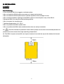
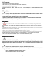
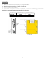
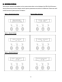
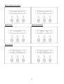
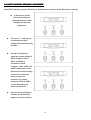
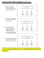
USER MANUAL
PIP-LC Series 800W~11KW
V 1.3
WWW.MPPSOLAR.COM
TABLE OF CONTENTS
A. INTRODUCTION ...................................................................................................1
A-1 Description.........................................................................................................1
A-2 Features..............................................................................................................2
A-3 Appearance .......................................................................................................3
A-3-1 Front Panel ..........................................................................................3
A-3-2 Outline...................................................................................................4
B. INSTALLATION.......................................................................................................8
B-1 Safety..................................................................................................................8
B-1-1 Positioning............................................................................................8
B-1-2 Transporting ........................................................................................9
B-1-3 Installation............................................................................................9
B-1-4 Operation..............................................................................................9
B-1-5 Maintenance and Service ..................................................................9
B-2 Mounting ...........................................................................................................10
B-3 Wiring .................................................................................................................11
B-3-1 Inspection .............................................................................................11
B-3-2 Connection ...........................................................................................11
C. OPERATION ...........................................................................................................15
C-1 Prior to Startup..................................................................................................15
C-2 Operations Procedures......................................................................................15
C-3 Operation Modes.................................................................................................16
C-3-1 System Block Diagram.........................................................................16
C-3-2 AC Priority / AC Mode...........................................................................16
C-3-3 DC Priority / Inverter Mode………..........................................................16
C-3-4 Battery Mode…….....................................................................................17
D. SYSTEM STATUS & SETTING .............................................................................18
D-1 Output Voltage & Frequency Adjustment.........................................................20
D-2 Charging Current / Battery AH Adjustment......................................................21
D-3 New LCD Menu Setting.........................................................................................22
E. SPECIFICATION .........................................................................................................23
E-1 Other Useful Information ………………………………………………………………………..25
F. TROUBLESHOOTING ...............................................................................................27
F-1 Common Error Codes ………………………………………………………………………………27
A. INTRODUCTION
A-1 DESCRIPTION
The PIP-LC series is designed to have access to dual input source; one is AC source from a grid, and the
other is DC source from a solar array. This series is a powerful all-in-one solution, not only delivering
unsurpassed clean true sine wave output power and combining this with a selectable multistage battery
charging current but also converting sunlight into clean energy. This series features durable and
continuous 24-hour operation. Consequently, it is applicable to any kind of loads such as air conditioner,
home appliances, consumer electronic and office equipment. The built-in 5-stage intelligent charger
automatically charges any type of batteries without the risk of overcharge. The compact and modular
design makes utility interactive installations easier and more cost effective. It is a high quality product
that offers the best price-performance ratio in the industry.
*SPLIT PHASE version:
version standard PIP-LC series comes in single phase 110V or 220V models, except for
8kw or larger which is only available in 220V. For US/Canadian customers or countries that use both
110V/220V loads, Split Phase versions may be special ordered; these are available only in 4kw (24v)
and 6kw (48v) at the moment. For more information, please see “A-2 FEATURES”.
1
A-2 FEATURES
1. Multiple microprocessor design base
2. Compatible with both linear and non-linear load
3. Battery size support up to 600AH* (*based on C/10 charging rate at 60A charging current, though
larger sized batteries can still be used). System design is based on leadlead-acid batteries only.
only
4. 24-hour inverter operation
5. DC start and automatic self-diagnostic function
6. THD less than 3%
7. High efficiency design to save electricity; low heat dissipation in extended operation
8. Designed to operate under harsh environment
9. 3U 19” wall-mounted design
10. Solar power charger with maximum 50A from an array
11. Detachable front panel for remote monitoring (via RJ45 straight-through network cable only)
Single-Phase Version (Standard)
Single phase models come in either 110V or 220V both input and output terminal will have 1L and 1N,
as shown below:
G
L
N
N
L
Split-Phase Version (only available on 4kw and 6kw models)
Split phase models accept input of 220V only (L-N) but will have an additional L on the output terminal,
so a L-N-L is available for connecting either 110V (using 1L) or 220V (using both L). Most countries that
use both 110V/220V would have 2 hotwires of 110V of opposite phase to each other, forming 220V.
Split phase model’s terminal would appear as below:
Output
G
L2
N
Input
L1
2
N
L
A-3 APPEARANCE
A-3-1 Front Panel
1. LCD Display:
Display This indicates the PIP-LC operation information, including PIP-LC status, input/output
voltage, input/output frequency, battery voltage, battery capacity left, output load, inside temperature,
and the times of history events.
Up--key
key: Use to navigate upward in the LCD menu of PIP-LC.
2. Up
Down--key
key: Use to navigate downward in the LCD menu of PIP-LC.
3. Down
*Holding this button down simultaneously with the Up-key will switch off the PIP-LC.
4. EnterEnter-Key:
Key This button is used to key in and confirm data input in the PIP-LC.
*Holding this button down with Down-key will switch on the PIP-LC.
*In battery operation mode, press this button with Up-key simultaneously will disable the buzzer.
(red): To indicate the PIP-LC is in fault condition because of PIP-LC shutdown or
5. Fault LED (red)
over-temperature.
6. Warning LED (yellow): To indicate the PIP-LC in the status of overload, bypass and battery back-up.
Please note warning LED will also light up when inverter switches to battery power under AC mode
(power outage), or when inverter switches to AC power under DC mode (battery low).
(green): To indicate the PIP-LC operating normally.
7. Normal LED (green)
SYSTEM TEST/MUTE
TEST/MUTE key:
key Up-key and Enter-key are pressed simultaneously to mute system buzzers
under normal conditions. However if overload or critical conditions occur these alarms cannot be
disabled.
3
A-3-1 Outline
800W Wall Mounted Type
4
1.6KW/2.4KW Wall Mounted Type
5
4KW / 6KW / 8KW Wall Mounted Type
6
11KW Wall Mounted Type
7
B. INSTALLATION
B-1 SAFETY
B-1-1 Positioning
1. Do not put the PIP-LC on rugged or declined surface.
2. Do not install the PIP-LC system near water or in damp environments.
3. Do not install the PIP-LC system where it will be exposed to direct sunlight or heat.
4. Do not block ventilation openings in the PIP-LC system or leave objects on top of the PIP-LC.
5. Keep the PIP-LC far away from heat-emitting sources.
6. Do not expose it to corrosive gas.
7. Ambient temperature: 0°C - 40°C
8. Do not position the PIP-LC upside down.
9. Do not position the PIP-LC where debris such as dust can easily accumulate
10.
The PIP-LC should be positioned indoors where people can not touch it accidentally because of
potential skin burns caused from high operating temperatures.
11. The PIP-LC requires at least 30 cm of space clearance from both the top and the bottom for thermal
dissipation.
8
B-1-2 Transporting
1. Disconnect all power cables if necessary.
2. Be careful not to drop/damage the PIP-LC while transporting.
3. Don‘t move the PIP-LC upside down.
4. Please transport the PIP-LC system only in the original packaging (to protect against shock and
impact).
B-1-3 Installation
1.
Connect the PIP-LC system only to a grounded shockproof wiring system to avoid electric
shocks resulting from current leakage.
2. Place cables in such a way that no one can step or trip over them.
3. Keep wire lengths between the array and the PIP-LC as short as possible to minimize voltage losses.
4. The installation must be performed by qualified personnel.
B-1-4 Operation
Do not disconnect the main cable on the PIP-LC system or the building wiring socket outlet
1.
during operation. This would cancel the protective grounding of the PIP-LC system and of all connected
loads.
2. The PIP-LC has its own internal power source (capacitors). The output terminals may be live even when
the PIP-LC is not connected to the AC supply.
3. Ensure that no fluids or other foreign objects enter the PIP-LC system.
4. Disconnect input power in rear panel if you will not use it for long period. If the PIP-LC is stored over 3
months, please supply power to the PIP-LC for at least 24 hours to ensure battery fully recharged.
5. Do not wear any jewelry or metallic objects when working with battery bank.
B-1-5 Maintenance and Service
1.
Caution - risk of electric shock.
Even after the unit is disconnected from the main power supply (building wiring socket outlet),
components inside the PIP-LC system are still connected to the battery and are still electrically live and
dangerous. Before carrying out any kind of servicing and/or maintenance, disconnect the batteries and
verify that no current is present.
2.
Batteries may cause electric shock and have a high short-circuit current.
Please take the precautionary measures specified below and any other measures necessary when
working with batteries:
- remove wristwatches, rings and other metal objects
- use only tools with insulated grips and handles.
9
B-2 MOUNTING
1.
2.
Make sure a wall surface or a solid place can support the PIP-LC.
Mark the bracket hole positions of the PIP-LC on the wall.
3. Use a screw driver to fix the PIP-LC
4. If more holes are required to be drilled on the bracket, make sure no metal shavings are left inside
the PIP-LC. It could result in a short circuit when PIP-LC is operating.
Hole Diameter
800W~2400W
4000W~8000W
Upper Hole
9.5mm
15mm
Lower Hole
7mm
10mm
10
B-3 WIRING
B-3-1 Inspection
1.
The system may be installed and wired only by qualified electricians in accordance with applicable
safety regulations.
2. When installing the electrical wiring, please note the nominal amperage of your incoming feeder.
3. Inspect the packaging carton and its content for damage. Please inform your shipper immediately
should you find signs of damage. Please keep original packaging in a safe space for future use.
4. Please ensure that incoming feeder is isolated and secured to prevent it from being switched back
again.
B-3-2 Connection
Connection
1. Grounding
-AC and DC Grounding: The PIP-LC has to be connected to a grounded permanent wiring system; and
the array has to be grounded as well. AC and DC are separately grounded.
2. AC Input / Output Terminals
-Utility (Input):
Recommended AC wire size:
Capacity \ Input voltage
100/110/120V
220/230/240V
800W
AWG 12 / 3.5mm2
AWG 12 / 3.5mm2
1.6KW
AWG 12 / 3.5mm2
AWG 12 / 3.5mm2
2.4KW
AWG 10 / 5.5mm2
AWG 12 / 3.5mm2
4.0KW
AWG 6 / 14 mm2
AWG 10 / 5.5mm2
6.0KW
AWG 4 / 22 mm2
AWG 8 / 8.0 mm2
8.0KW
N/A
AWG 6 / 14 mm2
11.0KW
N/A
AWG 4 / 22 mm2
100/110/120V
220/230/240V
-Load (Output):
Recommended AC wire size:
Capacity \ Input voltage
800W
AWG 12 /
3.5mm2
AWG 12 / 3.5mm2
1.6KW
AWG 12 / 3.5mm2
AWG 12 / 3.5mm2
2.4KW
AWG 10 / 5.5mm2
AWG 12 / 3.5mm2
4.0KW
AWG 6 / 14 mm2
AWG 10 / 5.5mm2
6.0KW
AWG 4 / 22 mm2
AWG 8 / 8.0 mm2
8.0KW
N/A
AWG 6 / 14 mm2
11.0KW
N/A
AWG 4 / 22 mm2
NOTE: each recommended wire size above applies to EACH of L/N/G inside a power cable.
11
3. DC Input Terminals
- Array (Input):
*
Make sure the open circuit voltage (Voc) of the PV array is less than the DC maximum
input voltage and the short circuit (Isc) is less than the DC maximum charging current of the built-in
solar charge controller. See SPECIFICATION for more details.
Recommended DC wire size for PV input:
Capacity
Size
800W
1.6KW
2.4KW
5.5mm2 (AWG 10)
4.0KW
6.0KW
8.0KW
*
Make sure electric polarity is correct when connecting DC terminals.
WARNING: Incorrect electric polar connection will damage the PIP-LC!
*
Whenever a PV array is exposed to sunlight, it converts sunlight into electric power and
results in shock hazard at its output wires and terminals. To avoid the risk of shock, DO NOT leave
open wires unattended and cover the array with an opaque material before wiring connections.
- Solar Connector
*Solar connector is affixed 2 cables with Tyco terminals compatible with output terminals of a
module’s junction box.
12
4. Fuses and breakers:
Properly sized fuses and breakers should be installed between each important junctions, i.e. PV <->
Controller, Controller <-> Battery, Battery <-> Inverter, and Inverter <-> AC loads. As a general rule of
thumb, follow the formula below when selecting a properly sized fuse/breaker:
Amp = 1.25 * Isc of ccircuit
ircuit current
For more information, please consult your electrician for guidance.
5. Communication and Remote Monitoring:
Remote monitoring can be achieved by connecting the detached LCD module to the remote control
port with ONLY straightstraight-through 11-toto-1 RJ45 cable.
cable
*
DO NOT use cross-over or any other type RJ45 cable as this can cause monitor to function
incorrectly or cause damage!
6. Battery:
Connect the battery terminals to the battery terminals on PIP-LC and make sure polarity is correct!
WARNING: incorrect polarity may blow fuse and cause internal damage to inverter.
Recommended battery wire size:
Model
Max Current
Wire Size
800W
67amp
AWG 4
1.6KW
67amp
AWG 4
2.4KW
100amp
AWG 2
4.0KW
167amp
AWG 00
6.0KW
125amp
AWG 0
8.0KW
167amp
AWG 00
NOTE: for 6KW/8KW inverters, battery resistor cable (see below) may be included for your
convenience. Be sure to apply it in between the battery and inverter for at least 5 seconds before
directly connecting the battery to your inverter terminal. This will help reduce the sparks during
13
connection.
*
Inverter may be turned OFF, but can still carry live electricity.
WARNING: if you intend to service the inverter, please ensure all power sources (AC, battery etc) are all
disconnected. Also, capacitors inside the inverter may still carry charge and it is strongly
disconnected
recommended that the capacitors are first discharged before working with internal PCBs to avoid
damage to system. The above battery resistor can be used to discharge the capacitors.
7. System Schematic Concept:
14
C. OPERATION
C-1 PRIOR TO STARTUP
1. Ensure the PIP-LC is in a suitable positioning.
2. Check and ensure all inputs cables are secured.
3. Make sure the load is disconnected or in the “OFF” position.
4. Check if input voltage meets the PIP-LC rating required.
5. Ensure batteries, loads (turned off), and AC cables are properly connected before switching on the
PIP-LC.
C-2 OPERATIONS
OPERATIONS PROCEDURES
Please follow the instructions below for PIP-LC operation.
1. Connect AC source (optional). *This inverter requires DC power to start, and AC is optional.
2. By pressing the Enter
Enter--key and the Down
Down--key simultaneously for about 3 seconds
seconds, system greetings will
display and inverter will start up after two beeps and Normal LED lights up to indicate the power is from
its bypass AC main to the load.
3. When the DownDown-key and the UpUp-key are pressed simultaneously for 3 seconds,
seconds the PIP-LC will be
turned off after two beeps. The system will remain in standby mode (Normal LED will keep blinking) until
AC input is completely disconnected.
15
C-3 OPERATION MODES
C-3-1 PIPPIP-LC System Block Diagram
C-3-2 AC Priority / AC Mode
System default is AC priority mode. There are two main loops when AC utility is normal: the AC loop
and the battery charging loop. The AC output power comes from AC utility input and passes through
static switch to support power to load. The battery charging voltage comes from AC utility input and
converted by AC/DC charger to support battery-charging power. If solar power is sufficient, the solar
charger (optional) will also provide charging power to battery.
C-3-3 DC Priority Mode / Inverter Mode
A new feature of the system provides the option for users to change in the LCD from “AC priority / AC
Mode” to “DC Priority / Inverter mode”. In this mode, DC power will be priority and system will draw
power from battery whenever possible. When battery is low, system will automatically switch to AC for
quick boost charging to 14.5V and left on float at 14V for 2 hours before it switches back to DC mode
again. If AC power is unavailable the system will enter Battery mode. Solar charging will remain in
operation whenever possible (minimum working voltage 11.7V±0.5V@12V).
16
C-3-4 Battery Mode (AC utility failure)
When there is insufficient solar power and AC power is unavailable, the system will enter Battery mode.
In this mode the PIP-LC will convert all power from battery bank into usable AC electricity, thereby
supplying power to loads.
17
D. SYSTEM STATUS
This section contains information on the system status that can be displayed via PIP-LC’s LCD screen.
Use Up/Down key to select/display various system parameters as shown in LCD below. This screen will
refresh once the system power is enabled.
Input / Output Power Spec
System Mode & Status
Input / Output Voltage
Input / Output Frequency
18
Battery Voltage and Capacity
Output Power
System Temperature
History Record
19
D-1 OUTPUT VOLTAGE & FREQUENCY ADJUSTMENT
After PIP-LC startup, press the Down-key to find the screen and then press Enter-key for setting.
In this screen, press
Enter-key to enter the
following steps for output
voltage and frequency
adjustment.
The cursor (→) will pop up
to indicate the output
voltage and frequency newly
selected.
Use Up or Down-key to
adjust the output voltage (if
220V configure, 220V,
230V, and 240V is
selectable; if 110V
configure, 110V, 115V, and
120V is selectable). Press
Enter-key to confirm voltage
and then the cursor will
move to frequency
selection. The output
frequency (50Hz or 60Hz)
can be adjusted by the
same key operation.
Once the correct voltage is
selected, press Enter-key
again to save the selection.
20
D-2 CHARGING CURRENT
CURRENT / BATTERY AH ADJUSTMENT (for prepre-2011 models)
models)*
In this screen, press
Enter-key to enter the
following steps for general
battery AH adjustment.
The cursor (→) will pop up
to indicate the battery AH
newly selected.
Use Up or Down-key to
select the battery AH
(100AH, 200AH, 300AH,
400AH, and 600AH
selectable). Press Enter-key
to confirm your battery AH.
Once the correct battery AH
is selected, press Enter-key
again to save the selection.
*NOTE: this setting is for models pre-2011 only. Charging current adjustment has now been
simplified to Low-Med-High Setting. Please see “D-3 NEW ADDITIONAL LCD MENU SETTING”
for more detail.
21
D-3 NEW ADDITIONAL LCD MENU SETTINGS
I / P Voltage Range Setting
Default : Input Voltage : LO = 170V,HI = 270V. Input Frequency : 45Hz~ 70Hz
LO : 120V ~ 200V( One Touch: +/- 1V)
HI :
250V ~ 280V( One Touch: +/- 1V)
1. Return point= +/_ 10V from the transfer point.
2. Press Enter to enable the setting. No need to re-start the inverter.
O/P Voltage /Frequency Setting
Default: 220VAC , 50HZ
Voltage: 220VAC / 230VAC / 240VAC
Selectable
Frequency: AC= Synchronized to AC., DC= 50HZ / 60HZ
Selectable
Press Enter to confirm. *NEED TO RESTART INVERTER.
AC/DC Prior Setting Functioning only under AC Mode. *This feature requires minimum 24V.
Default: AC Prior.
Select "AC MODE" for AC Prior ., "INVERTER MODE" for DC Prior.
1. Under “DC Prior” if battery voltage is too low, it will auto change to AC if AC normal.
2. Press Enter to confirm. *NEED TO RESTART INVERTER.
Battery Shutdown Voltage & Current Setting ( 48V/ 24V)
Default: 40V(20V).
HIGH: 42V ( 21V)/ MIDDLE: 40V ( 20V) / LOW :38V ( 19V)
Selectable
1. Low Voltage warning point: 42.5 V( 21.5V)
2. Press Enter to enable the setting. No need to re-start the inverter.
Battery Charging Current Setting
Default: Middle
LOW ( 100AH) - MIDDLE ( 300AH)
- HIGH ( 600AH)
Press Enter to enable the setting. No need to re-start the inverter.
(OPTIONAL,
(OPTIONAL, extra charge)
charge) Green Power On/Off Setting *Requires minimum 24V & only under Inverter Mode.
Default: Off.
Green Power Off: System running continuously.
Green Power On: System Auto Shutdown when Load < Pre-setting
Press Enter to enable the setting. No need to re-start the inverter.
(OPTIONAL,
(OPTIONAL, extra charge)
charge) Green Power Mode & Time Setting *Requires minimum 24V.
Default: Time period for next detecting: 30 Sec.
Time: 15 Sec., 30 Sec., 45 Sec. 60 Sec selectable.
1. Detecting load: ~20w
2. When the load is less than 20w,the inverter will auto turn off and count the pre-set time ( 30 Sec.), then,
re-start.
3. Press Enter to enable the setting. No need to re-start the inverter.
22
E. SPECIFICATIONS
Model
Capacity
VA / Watt
PIPPIP-812LC
PIPPIP-1624LC
PIPPIP-2424LC
1.2KVA / 800W
2.4KVA / 1600W
3.6KVA / 2400W
Nominal Voltage
220Vac; 110Vac
Range
Input
120-275Vac ; 60-135Vac
Frequency
50Hz / 60Hz
Line Low Transfer
120VAC ± 2% ; 60VAC ± 2%
Voltage
Acceptable Voltage Range
Line Low Return
130VAC ± 2% ; 65VAC ± 2%
Line High Transfer
275VAC ± 2% ; 135VAC ± 2%
Line High Return
260VAC ± 2% ; 130VAC ± 2%
Voltage
110/115/120VAC or 220/230/240VAC resettable via LCD panel)
Voltage Regulation (Battery Mode)
< 3% RMS for entire battery voltage range
Frequency
50Hz or 60Hz
Frequency Regulation (Battery
Output
±0.1Hz
Mode)
Power Factor
0.8
Waveform
Pure Sine Wave
Peak Efficiency
Transfer Time
( 45Hz - 70Hz)
Overload
Line Mode
Protection
Battery Mode
80%
Circuit Breaker
110% ~ 150% for 30 sec. , >150% for 200ms
Typical
Battery Voltage
85%
< 8 ms.
12Vdc
24Vdc
24Vdc
Battery
Max. Charging Current
>
40A
>
50A
INVERTER status, I/P&O/P Voltage Frequency, Load%,
LCD
Display LCD
Battery Voltage/%, Charge current, Temperature, Model
LED
Normal (Green), Warning (Yellow), Fault (Red)
Battery Mode
Beeping every 4 seconds
Low Battery
Beeping every second
Inverter Fault
Beeping Continuously
Audible Alarm
Overload
Beeping twice per second
Operation Temperature
Environment
0-40 degree C; 32-104 degree F
Relative Humidity
0-95% non-condensing
Audible Noise
Net Weigh (Kgs)
Less than 55dBA (at 1M)
14
21
23
298*400*150
298*450*190
298*450*190
Physical
L*W*H (mm)
* Specifications are subjected to change without prior notice.
23
Model
Capacity
VA / Watt
PIPPIP-4024LC
PIPPIP-6048LC
PIPPIP-8048LC
PIPPIP-11048LC
5KVA / 4000W
6KVA / 6000W
8KVA / 8000W
8KVA / 8000W
Nominal Voltage
Voltage Range
Input
Acceptable Voltage
Range
Frequency
Line Low Transfer
220Vac only
120-275Vac ; 60-135Vac
120-275Vac
50Hz / 60Hz
120VAC ± 2% ; 60VAC ± 2%
Line Low Return
Line High Transfer
Line High Return
Voltage
Output
220Vac; 110Vac
Voltage Regulation (Battery Mode)
Frequency
Frequency Regulation (Battery Mode)
Power Factor
Waveform
Transfer Time
85% (90% with Green Power Mode)
Line Mode
Circuit Breaker
Battery Mode
110% ~ 150% for 30 sec. , >150% for 200ms
Typical
Battery Voltage
Battery
120VAC ± 2%
130VAC ± 2% ; 65VAC ± 2%
130VAC ± 2%
275VAC ± 2% ; 135VAC ± 2%
275VAC ± 2%
260VAC ± 2% ; 130VAC ± 2%
260VAC ± 2%
110/115/120 or 220/230/240VAC
220/230/240VAC adjustable via LCD
adjustable via LCD
< 3% RMS for entire battery voltage range
50Hz or 60Hz
±0.1Hz
0.8
1.0
Pure Sine Wave
Peak Efficiency
Overload Protection
( 45Hz - 70Hz)
< 8 ms.
24Vdc
48Vdc
Max. Charging Current
> 60A
> 85A
INVERTER status, I/P&O/P Voltage Frequency, Load%, Battery Voltage & %, Charge
LCD
current, Temperature, Model
Display LCD
Audible
Alarm
LED
Battery Mode
Normal (Green), Warning (Yellow), Fault (Red)
Beeping every 4 seconds
Low Battery
Beeping every second
INVERTER Fault
Beeping Continuously
Overload
Operation Temperature
Beeping twice per second
0-40 degree C; 32-104 degree F
Environment
Physical
Relative Humidity
Audible Noise
Net Weigh (Kgs)
L*W*H (mm)
0-95% non-condensing
49.2
415*600*260
Less than 55dBA (at 1M)
51.4
53.6
415*600*260
415*600*260
110.4
452*670*277
* Specifications are subjected to change without prior notice.
OPTIONAL BUILT-IN SOLAR CHARGE CONTROLLER
Battery/System Voltage
12V (800W)
24V (1.6~4KW)
48V (6~11KW)
(6~11KW)
13.8V
27.7V
55.2V
11.7V±0.5V
23.5V±1V
44V±3V
Max Solar Input Voltage
22.0V
45.0V
100V
Max Solar Input Current
50A
50A
50A
Max. Charging Current
50A
50A
50A
Reverse Polarity Protection
YES
YES
YES
Reverse Current Protection
YES
YES
YES
Charging Voltage
Minimum Solar Working Voltage
W*D*H
112mm * 80mm * 50mm
*Please ensure PV input voltage and current do not exceed above input specifications.
24
E-1 OTHER USEFUL INFORMATION
1. Battery Voltage Alarm & Shutdown
Battery Voltage.
Battery Low Alarm
Battery Low Shutdown
DC range
12V
10.8V
10.3V
10.5V~14.5Vdc
24V
21.5V
20.0V
20V~29.3Vdc
48V
42.5V ~ 43.0V
40.0V
40V~58.5Vdc
2. High Temperature FAULT alarm
System Internal temperature
60°C
Heat Sink temperature
80°C
3. Inverter Inrush Current:
Model Name
Inrush Current (220Vac, 5 cycles)
Inrush Current = KVA
812LC
9.5A
2.1KVA
1624LC
19A
4.2KVA
2424LC
24.5A
5.4KVA
4024LC
33A
7.2KVA
6048LC
72A
15.8KVA
8048LC
84A
18.5KVA
**Maximum surge is purposely lowered for operational safety and stability.
4. System Current Consumption (with & without Optional Green Power Mode)
Mode)
Note: this feature will activate when load is <~20w. Values below are approximate based on average.
Without Green Power Mode
With Green Power Mode
812LC
3.6A (reference)
< 0.63 A
1624LC
2.6A (reference)
< 0.42A
2424LC
3.2A (reference)
< 0.42A
4024LC
3.8A (reference)
< 0.63A
6048LC
2.7A (reference)
< 0.42A
8048LC
3.8A (reference)
< 0.42A
5. Circuit Breaker Rating (Based on 220v)
812LC
8A
1624LC
8A
2424LC
20A
4024LC
30A
6048LC
40A
8048LC
40A
25
5. Inverter Charging Voltage Chart
Under DC priority (Inverter mode), the inverter will
transfer to AC line mode after the battery low
shutdown. And then the AC power continues to
charge the batteries.
When the batteries are boost-charged up to the
highest voltage like the A point (14.5/29.3/58.5Vdc)
in the drawing, the inverter will start to count
count for 2
hours and then it can back to inverter mode again.
26
F. TROUBLESHOOTING
The following guideline may be helpful for basic problem solving.
No.
INVERTER STATUS
POSSIBLE CAUSE
AC utility power is normal. NVERTER is
1
3
Charger PCB is
1. Replace the charger PCB.
damaged.
2. Replace the fan.
2.
Fan is damaged.
3. Restart INVERTER
3.
Unknown
1.
running normally, but fault LED lights up.
Buzzer beeps continuously.
ACTION
AC utility power is normal but INVERTER is
Overload
Please reduce the critical load to
overloaded. Warning LED lights up and
100%< load< 125%
<100%.
AC utility power is normal. Warning LED does
Overload
Please reduce the critical load to
not fade out and buzzer beeps per 0.5
125%< load<150%
<100%.
AC utility power is normal. Warning LED
Overload
Please reduce the critical load to
lights up and buzzer beeps continuously.
150%< load
<100%.
AC utility power fails .The load is supplied by
1. AC utility power
1. Reduce the less critical load in
buzzer beeps per second.
4
second.
5
battery power. Buzzer alarm sounds every 4
6
failure.
seconds.
order to extend backup time.
2. AC input connection
2. Please check the rated input or
may be not correct.
7
connected line.
AC utility fails. INVERTER is in battery backup
Battery power is
INVERTER will shut down
mode. Buzzer alarm beeps every second.
approaching low level.
automatically. Please save data or
turn off the loads soon.
AC utility power fails. INVERTER has shut
8
Battery runs out
INVERTER will restart up when AC
down automatically.
utility power is restored.
F-1 COMMON ERROR CODES
please do not attempt to engage selfself-repair or replacement of internal PCBs without prior
authorization as this will avoid warranty! Contact your seller for further instruction.
Problems
AC Abnormal
LCD Display
I/P Polarity ERR
Solutions
Check(Only 120V Series) :
AC INPUT N – GND VOL > 1V
Solutions : Improve the grounding of AC main.
27
AC Fail
Check :
(Under inverter mode, but can
not transfer to line mode.)
a. AC Voltage :
*** 60V > AC Voltage > 135V (120V Series)
*** 120V > AC Voltage > 270V (220V Series)
b. AC Frequency :
*** 45Hz > AC Frequency > 70Hz
If no, replace control & Main PCB.
DC Abnormal
DC_BUS Fail
Check : (Battery Voltage)
*** 1.2K : Battery Voltage > 15.0V
*** 2.4K / 3.6K / 5K : Battery Voltage > 30.0V
*** 6K / 8K : Battery Voltage > 60.0V
If no, replace battery.
Charger Fail
Check : (Charger Voltage)
*** 1.2K : 11.2V > CHG. VOL > 15V
*** 2.4K / 3.6K / 5K : 22.5V > CHG. VOL > 30V
*** 6K / 8K : 45V > CHG. VOL > 60V
Solutions : (OFF
(OFF AC)
*** Under cold start, if Inverter Mode OK, replace the Control PCB
*** Under cold start, if Inverter Mode N.G., replace control & Main
PCB
Over
Temperature
Temp Fail
Check :
*** If The Temperature Of the inverter is really high
*** Remove Some Unnecessary Loads
*** That The Fan is Normal
*** The Temperature Sensor Circuit..
Solutions :
*** Restart the inverter. If N.G., replace the control PCB
Fan Abnormal
Fan Fail
Check :
*** That The Fan is Normal
*** The Fan’s Sensor Circuit.
Solutions :
*** Restart the inverter. If N.G., replace the control & main PCB
Over Load
Over Load
Check :
*** If LCD Display Output Power > 110 %
*** Remove Some Unnecessary Loads to be Less
Than 90%
*** Restart the inverter to Enter Into the Inverter mode
28
Inverter
Abnormal
Inverter Fail
*** Remove the load
Check :
*** 1.2K ~ 3.6K Check PSDR Board DC Fuse
Damaged;
*** 5K ~ 8K :Check Fuse Board DC Fuse Damaged;
*** Check if power PCB is damaged..
Solutions :
*** If DC Fuse or Power Components Damaged, Please replace
the main PCB
*** If no damaged, the inverter may be output shorted or output
inrush current cause the inverter protection. Please restart the
inverter.
Can’t Cold
Start
Check :
a. LCD Display Panel :
*** Check it LCD Display Panel is connected or inserted properly.
b. Battery Voltage (for initial start and auto
auto restart) :
1.2K : 10.5V > Batt. VOL
2.4K / 3.6K / 5K : 21.5V > Batt. VOL
6K / 8K : 40V > Batt. VOL
Solutions :
*** Replace the battery
29