1
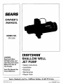
SEARS
OWNER'S
MANUAL
MODEL NO.
390.2505
CAUTION:
Read and Follow
All Safety Rulesand
Operating Instructions
Before First Use of
This Product.
Save ThisManual For
Future Reference.
I:RI:IFTSMRN°
SHALLOW WELL
JET PUMP
• Safety Instructions
• Installation
• Electrical
• Maintenance
• Repair Parts
Sears, Roebuck and Co., Hoffman Estates, IL 60179
PRtNTED
iN U.S.A.
U.S.A.
FormNo. F642-04071
(8/3/04)
CONTENTS
Introduction
Warranty
INTRODUCTION
...............................................................
2
.....................................................................
Major System Components
........................................
Installation ..................................................................
Electrical ..................................................................
Maintenance
............................................................
Please read our instructions
before installing and using
your pump. This will help you obtain the full benefits
of the quality and convenience
built into this equipment. It will also help you avoid any needless service
expense
resulting
from causes beyond
our control
which are not covered by our w_ty.
2
3
4
5_5
7-8
Troubleshooting
.........................................................
Repair Parts .........................................................
9
10-11
RULES FOR SAFE INSTALLATION
1.
2.
3.
4.
5.
6.
7.
AND
Read the Owners
Manual
and Rules for Safe
Operation
and Installation Instructions
carefufiy.
Failure to follow these Rules and Instructions could
cause serious bodily injury, and/or property damage.
Check your local electrical wiring codes before installation. If your local codes are not followed, your
pump will not work to its full rated capacity and
could present a fire hazard. If in doubt, contact your
local power company.
BE SURE your pump installation
meets all local
plumbing,
pump and well codes.
8.
While installing your pump, always keep the well
covered to prevent leaves and foreign matter from
falling into the well, contaminating
the water
and/or causing possible serious damage to the mechanical operation
of the pump.
12. Periodically
9.
electrical
circuit
Complete pump and piping system MUST be pretected
against
below
freezing
temperature.
Allowing the pump or piping to freeze could cause
severe damage and voids the Warranty.
BE SURE the line voltage and frequency of the electrical current supply agree with the motor wiring
as shown on motor nameplate.
10. The correct fusing and wiring sizing is essential to
proper motor operation.
Use recommended
fusing
and wire size data in the manual (Pages 5 and 6).
11. Pump water only with this pump.
inspect
pump and system components.
13. Relief valve must be capable
flow at 75 PSI.
of passing
full pump
[kWARNIN_
Pump body may explode
if used as a
booster
pump unless
relief valve capable
of passing full pump flow at 75 PSI (517 kPa) is installed.
Always test the water from web for purity before
using. Check with local health department
for testing procedure.
Before instaUing or servicing your pump, BE SURE
pump power source is disconnected.
BE SURE your pump
grounded.
OPERATION
[a_ CAOTION]Motor normally operates at high temperature and will be too hot to touch. It is protected
from
heat damage during operation by an automatic internal
cutoff switch. Before handling
pump or motor, stop
motor and allow it to cool for 20 minutes.
is properly
2
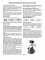
MAJOR COMPONENTS
Tank and Air Volume
The tank serves two
of water, so that the
time water is drawn
maintains a cushion
Control
functions.
It provides a reservoir
pump doesn't need to start every
from a fixture in the house, and it
of air under pressure.
AND WHAT
THEY DO
your elevation is 3,000 feet above sea level, you would
then be pumping
17 plus 3 or 20 feet. This is still satisfactory for shallow well pumping.
Horizontal
Piping
From
Well
To Pump
When Captive Air* Tanks are used, no air volume control is necessary. This tank is precharged
with air at the
factory.
When a Standard Tank is used, an air volume control
adds air to the tank when it is needed. See instructions
included with Air Volume Control for details on installation and operation.
On well point installations
where the horizontal
piping is more than 25 feet, a check valve should be installed as shown in Figure 3, Page 4.
Pressure
Horizontal Offset Piping Sizes
for Shallow Well Jets
Switch
The pressure
switch
provides
automatic
control.
When the pump is offset more than 25 feet from the
well, horizontal
piping should be increased
in size to
reduce friction losses. In no case should the offset piping be smaller than the suction tapping of the pump.
Model No.
Pump Starts At
Pump Stops At
1-1/4"
1-1/2"
2"
390.2505
30 Pounds
50 Pounds
Up to 25 Ft.
25 to 50 Ft.
50 to 200 Ft.
When used with a Captive Air* Tank, the precharge
may need adjustment.
See the Captive Air* Tank instructions for details.
Impeller
and Jet
The impeller of the pump rotates with the motor shaft,
causing the water to fly out from its rim by centrifugal
force. The rotation of the impeller creates a partial vacuum which pulls in more water. Part of the water is diverted back to the jet where it passes through
the
nozzle and venturi, reinforcing
the vacuum to draw in
more water and delivering
it at a high velocity to the
impeller.
Because of the shallow setting, the partial vacuum created by the pump is sufficient
to pull water to the
pump, therefore, the jet assembly is attached directly
to the pump.
Piping
In The Well
Discharge
When the pump is set a distance
from the house or
point of water use, the discharge pipe size should be
Increased to reduce pressure losses caused by friction.
1"
1-1/4"
1-1/2"
Up to 25 Ft.
25 to 100 Ft.
t 00 to 600 Ft.
Emergency
Relief "
Valve
tee and a plug as
Be sure the total lift from the pumping water level to
the pump does not exceed 20 feet if the pump is over
the well, or less if the pump is offset from the well.
Both figures arc for sea level - the maximum
lift at
which the pump can operate
satisfactorily
decreases
with the elevation at the approximate
rate of 1 foot per
1,000 feet of elevation.
Thus, if the lift is 17 feet and
Power
In some areas and with some installations,
an emergency power supply to guard against power failure is a
good idea. If you install an engine-generator
set for
emergency
backup power for your pump, supply the
generator
set manufacturer
with the nameplate
data
from the pump motor. He will then be able to provide
a generator
of the correct size to power your pump.
Also, be sure to add the load from any other accessories
(such as lights) that may be on the same circuit.
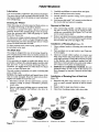
A Shallow well jet pump can be installed on a dug well,
drilled well or with a driven point. SEARS shallow well jet
pumps have a built-in check valve. In a dug or cased well,
a foot valve and strainer is recommended
and should be
installed 5 to 10 feet below the lowest level to which the
water will drop while pump is operating (pumping water
level), See Figure 3, Page 4. Your well driller can furnish
this information. The strainer should not be too close to
the bottom, or sediment may clog it. Before installing foot
valve, check to see that it works freely.
When using a foot valve, a priming
shown in Figure 1, is recommended.
Pipe Sizes
Figure
I
and piping
Priming Tee
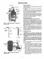
INSTALLATION
ReliefValve
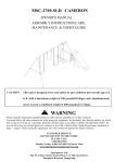
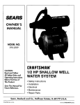
Pump Installation
SEARS jet pumps can be used with Captive _
Tanks
as shown in Figure 2.
For mounting pump to tank, purchase tank fitting Kit
No. 2788.
CRAFTSMAN Captive Air* Tanks are precharged
with
air at the factory. Check the tank Owner's Manual to
find if air charge needs adjustment.
Your pump requires 30 pounds for proper operation.
The jet pump can also be mounted
on standard horizontal tanks. A kit consisting of all necessary piping, elbows, and other fittings, is furnished with the tank for
mounting
pump using this method.
See Figure 3.
Instructions
are included with tank.
Plug
To Household
Water System
Built-in
Check Valve
Adapter
From
Weft
Switch
Plastic
Pipe
Air Volume Control
Included With Standard
Tank
Figure 2 - Typical Installation
Pressure Tank
- Captive
Plastic
NOTE:
Check Va_e used if
h°dz°ntal piping is
25. o_more
_
_t
Air e
Remove the 1/4" pipe plug, Key No. 13, Page 10, on
the jet portion of the pump body near the check valve.
Insert a 1/4" compression
fitting into this tapping. Cut
tubing to length and assemble the two fittings in the
air volume control and pump body. Use nuts, sleeves,
and inserts furnished.
P
1 1/4"
/Stee_
_{
Drive
Priming
Pipe
Foot Valve
Point
[AWA_
Never run pmnp
against
closed
discharge.
To do so can boil water
inside
pump,
causing
hazardous
pressure
in unit, risk of explosion
and possibly
scalding
persons
handling
pump.
DO NOT START MOTOR UNTIL PUMP HAS BEEN
FILLED WITH WATER.
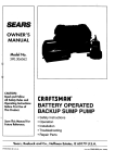
Dug or Cased Well
Relief
Valve
Priming
1.
To Household
Water System
AVC Port
From
Well
2.
Air Volume
Control Tube
Figure 3 - Typical Installation
Pressure Tank
the Pump
I_' CAUTIONI Never
run pump dry. Running
pump
without
water may cause pump to overheat,
damaging seal and possibly
causing
burns to persons
handling
pump. Fill pump with water before starting.
Drive
_'Coupling
Ddven
Tank
There is a 1-1/4" x 1/4" reducer bushing and a 1/4" x 1-1/2"
nipple supplied in the fittings package. Use the one that fits
into the air volume control tapping in the end of the tank
as shown in Figure 3. Use pipe compound on male threads.
Screw the air volume control on to the 1/4" fitting and the
right angle compression fitting into the bottom tapping of
the air volume control.
Well Seal
o.ock
vo,vo
Horizontal
Built-in
Check Valve
- Standard
4
Remove the priming plug. fill pump with water.
Replace priming plug. If a priming tee and plug
have been provided at the well head for a long horizontal run, be sure this tee is filled and the plug replaced, using pipe compound
on plug threads. See
Figure 1, Page 3.
Start the pump. Water win be pumped in a few minutes; the time depending
upon the depth to water,
and the distance of horizontal
run. If pump does
not prime, check for a possible leak on the suction
side of the pump. Reprime. Check to be sure suction lift - distance from water level to pump - does
not exceed 20 feet.
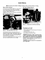
ELECTRICAL
Disconnect
Motor
Switch
power
before
working
on pump,
Settings
motor,
pressure
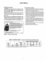
Dial Type Voltage
If the motor can operate at either 115 or 230 volts, it
is set at the factory to 230 volts. Do not change
motor voltage setting if line voltage is 230 volts, or if
you have a single voltage motor.
NOTICE: Never wire a 115 volt motor to a 230 volt line.
Remove
Motor
switch,
or wiring.
Selector
Power Supply Connections
End Cover
Figure 5 - Voltage
Set To 230 Volts, Dial Type
To change
to I 15 volts:
1. Make sure power is off.
Figure
4 - Removing
Motor
End Cover
You will need to remove the motor end cover to
change the voltage setting. The illustration above also
shows the pressure switch. If the power supply connection still needs to be made, the pressure switch
cover will need to be removed.
Your motor terminal board (located under the motor
end cover) should look like the one at right.
2. Turn the dial counter-clockwise
the dial window.
3. Reinstall
the Motor
4. Go to Wiring
until
115 shows
in
end cover
Connections,
Page 6.
[AWARNINGI Hazardous
voltage. Can shock, burn,
or kill. Connect ground wire before connecting
power supply wires. Use the wire size (including
the ground wire) specified in the wiring chart. If
possible, connect the pump to a separate branch circuit with no other appliances on it.
[AWARNING
I Explosion
a gas supply line.
hazard.
Do not ground
to
ELECTRICAL
Wiring
Connections
[_WARNING] ]Fire
a fire or seriously
ranty. The supply
motor nameplate
Connection
haTAtl'd. Incorrect
voltage can cause
damage the motor and voids the warvoltage must be within +-10% of the
voltage.
1. Connect the ground wire first as shown in Figure 6.
The grotmd wire must be a solid copper wire at least
as large as the power supply wires.
2. There must be a solid metal connection
between the
pressure switch and the motor for motor grounding
protection.
If the pressure switch is not connected
to the motor, connect the green ground screw in the
switch to the green ground screw under the motor
end cover. Use a solid copper wire at least as large
as the power supply wires.
NOTICE:
Dualwoltage
motors are factory wired for
230 volts. If necessary,
reconnect
the motor for 115
volts, as shown. Do not alter the wiring in single voltage motors.
Install, ground, wire, and maintain your pump In compliance with the National Electrical Code (NEC) or the
Canadian
Electrical
Code (CEC), as apphcable,
and
with all local codes and ordinances
that apply. Consult
your local building inspector
for code information.
3. Connect the ground wire to a grounded lead in a service panel, to a metal underground
water pipe, to a
metal well casing at least ten feet (3M) long, or to a
ground electrode
provided by the power company
or the hydro authority.
Motor wires connect here.
4. Connect
the power supply wires to the
switch as shown in Figure 6.
5. Reinstall the pressure switch cover.
-Power supply wires connect here.
230 Volt: Connect 2 hotwires (black and red
here and cap the wh te neutral)wire. It does
not matter which wire goes to which screw,
115 Volt: Connect one hot wire (black or red)
to one of these screws (it doesn't matter
which one). Connect the white (neutral) wire
to the other screw. Cap any remaining
black or red wires.
on the terminal
Procedure
pressure
screws.
green (or bare copper) ground wire
to the green ground screw.
3187 0398
Figure 6 - Pressure switch wiring
TABLE
h WIRING
CHART
-
Recommended
Fusing
and Wiring
Data
Distance in Feet From Motor to Meter
Motor
Horsepower
1/2
Max,
Load
Volts
115/230
Amperes
10.4/5.2
Branch*
Fuse
Rating
Amps
15/15
0'
51'
to
50'
to
100'
101'
201'
201'
401'
to
to
200'
300'
Wire Size
to
400'
to
500'
14/14
I 14/14
I 10/14t10/14
I 6/14I 5/12
• Time delayedfuses are recommended insteadof fusesin an vmotor circuit.
6
MAINTENANCE
Lubrication
It is not necessary
to lubricate
the pump or its motor.
The motor has two ball bearings lubricated for life. The
mechanical
shaft seal in the pump is water lubricated
and self-adjusting.
Draining
3.
4.
Carefully tap diffuser to remove from seal plate.
Remove canopy from end of motor.
5.
Partially unscrew
to one side.
6.
Hold motor shaft with 7/16" wrench on the flats on
the motor shaft and unscrew impeller.
for Winter
When the pump is to be disconnected
from service,
is in danger of freezing, it should be drained.
To drain an air volume control, remove AVC tubing and
turn (loosen) it 180 ° on the 1/4" pipe fitting in the tank.
This will permit any water remaining in the air volume
control to drain back into the tank.
plug, piping
The pump is designed for ease of servicing. Should repair or replacement
of the motor or seal be needed, the
pump and piping do not need to be disconnected
or
disturbed.
After unscrewing
impeller, carefully remove rotating part of seal by prying up on sealing washer,
using two screwdrivers
(see Figure 7A). Use care
not to scratch motor shaft.
2.
Remove seal plate from motor and place on flat surface, face down. Use a screwdriver
to push ceramic
seat out from seal cavity (see Figure 7B).
of Floating
Clean polished
cloth.
2.
Turn seal plate over so seal cavity is up. Clean cavity thoroughly.
Lubricate
outside rubber surface of ceramic seat
4.
half
surface
Seat (Figure 7C)
1.
3.
If it is necessary
to repair or replace the motor, it is a
good idea to replace the seal plate gasket and the shaft
seal, Key Nos. 4 and 5 of pump drawings,
Page 10.
Therefore, we suggest that you order these two items
to have on hand for future use.
two parts; a rotating
capacitor
1,
Installation
or hose at
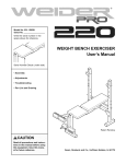
The Shaft Seal
The seal consists of primarily
and a ceramic seat.
clamp; move
Removal of Old Seal
or
Turn power to pump OFE Open a faucet to bleed off
pressure.
Remove the priming plug to vent the pump.
Drain the pressure
tank. Drain all piping to a point
below the freeze line.
To drain pressure tank, remove
lowest point in the tank.
capacitor
of floating
seat with
clean
with soapy water and press firmly into seal cavity
with finger pressure. If seal will not locate properly
in this manner, place cardboard
washer over polished face of seat and press into seal cavity using a
3/4" socket or 3/4" piece of standard pipe.
DISPOSE OF CARDBOARD
WASHER. Be sure
polished surface of seat is free of dirt and has not
been damaged by insertion. Remove excess soapy
water.
NOTICE: The highly polished and lapped faces of the
seal are easily damaged.
Read the instructions
thoroughly and handle the seal with care.
Installation
(Figure 7D)
1.
Disconnect
electric service
connect
wiring to pump.
switch tube.
(pull switch), and disDisconnect
pressure
1.
Reinstall seal plate using extreme
caution not to
nick or scratch ceramic portion of seal on motor
shaft.
2.
Remove capscrews
holding
Motor with impeller
and
removed.
motor to pump body.
diffuser
can now be
2.
Inspect shaft to make sure that it is clean.
3.
Clean face of sealing washer
\
685 O294
of Rotating
Part of Seal Unit
with clean cloth.
3/4" socket
Shaft
/ shoulder
Cardboard
washer
_
(SOl_li_
Rubber drive
w/eeal)
Polished
surface
\
Rubber
su_ace
4echanical sea[
rotating half
Sealing
face
Impeller
SealPlat
A-Seal removal-rotating
half
B-Seal removal-stationary
half
C-Stationary
Figure 7
7
half installation
D-Rotating
half installation
MAINTENANCE
4.
5.
HOW
Lubricate inside diameter and outer face of rubber
drive ring with soapy water and slide assembly on
motor shaft (sealing face first) until rubber drive
ring hits shaft shoulder.
Screw impeller onto the shaft until impeller hub
stops against shaft shoulder. This will automatically
locate seal in place and move the sealing washer
face up against seat facing.
A GASEOUS
Disconnect
power
Remove motor.
(a) Remove
to pump.
motor
wiring
from pressure
swttch.
Co)Remove
4 capscrews,
Key No. 17, Page
which hold the motor to the pump body.
(c) Remove motor,
(Key Nos. 1, 3,
Diffuser, Key No.
impeller exposed
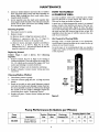
WELL
In some localities
well water contains
gases which
must be allowed to escape before the water is used.
This can be done as shown in Figure 8.
A good way of delivering gas-free water is to suspend
a pipe, closed at the bottom and open at the top, surrounding
the suction pipe, Figure 8. Since the gases
rise in the well casing, the water sucked down through
the pipe and into the suction pipe is free of gas. It is
imperative
that this type of well be vented to the outside of any enclosure.
Cleaning Impeller
1.
2.
TO HANDLE
Air
10,
Control
In Flowing
seal plate, impeller and diffuser,
6 and 7), Page 10, as a unit.
7, can now be lifted off and the
and cleaned.
Replacing Venturi
Follow
Steps
1 and
2 above,
for
Cleaning
Impeller.
1. Remove venturi, Key No. 9, Page 10, by turning it
counter-clockwise.
This will expose the nozzle, Key
No. 10, which can be removed by using a 5/8" hex
socket and turning it counter-clockwise.
2. To replace venturi, turn it clockwise until snug.
3.
Replace all parts.
on power.
Cleaning
Shallow
Well
motor
wiring
Jet
1.
Disconnect
Unscrew cleanout plug (Key No. 15, Page 10) from
pump.
Insert an ice pick or other small diameter pointed
tool into the nozzle and dislodge foreign material.
If it is not possible to push the obstruction
through
the nozzle or if the nozzle is damaged, follow instructions
above under "Replacing Venturi".
4.
Replace all parts.
on power.
to pump.
Connect
motor
wiring
390.2505
Not
to
pipe
valve
Scale
2369 0396
sloeve
cap
and turn
Figure 8
Pump Performance
Pump
Model
wire to hold
pipe sleeve
and turn
2.
3.
power
Connect
Wells
Flowing wells, or wells with little or no drawdown,
could create a special problem in air control in the operation of your water system.
In such cases, it is recommended
that you install a
Captive Air * Tank, in which an air control mechanism
is not required.
Suction
Description
1/2 HP Cast Iron
Shallow Well Jet
Size
I-I14"
(In Gallons per Minute)
Discharge
Size
1 n
Pumping Depth in Feet
Discharge
Pressure PSI
5'
10'
15'
20'
4O
8.2
7.3
6.2
5.0
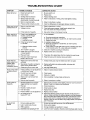
TROUBLESHOOTING
SYMPTOM
Motorwill not run
POSSIBLE CAUSE(S)
1. Disconnect switch is off
2. Fuse is blown
Motor is wired incorrectly
6. Pressure switch contacts are dirty
5. Refer to instructions on wiring
3.
Motor runs but no
water is delivered
Pump cycles too frequently
1. Pump in new installationdid
not pick up prime through:
a. Improper priming
b. Air leaks
c. Leaking foot valve
2,
Pump has lost prime through:
a. Air leaks
b. Water level below suction
of pump
Jet or impeller is plugged
4. Check valve or foot valve is stuck
in closed position
5,
Pipes are frozen
6. Foot valve and/or strainer are
buried in sand or mud
3,
4. Refer to instructions on wiring.Check and tighten all wiring.
6. Clean by sliding pieces of plain paper between contacts
1. Refer to instructionson wiring
2. Check with power company. Install heavier wiringif wire
size istoo small. See wiring instructions
3. See section below on too frequent cycling
1. In new installation:
a. Re-prime according to instructions
b. Check all connections on suction line, air volume control,and jet
c. Replace foot valve
]n installation already in use:
a. Check all connections on suction line, air volume control,
jet and shaft sea[
b. Lower suction line into water and re-prime. If receding water level
in well exceeds suction lift, a deep well pump is needed
3. Clean jet or impeller according to instructions
4. Replace check valve or foot valve
2.
5. Thaw pipes. Bury pipes below frost line. Heat pit or pump house.
6. Raise foot valve and/or strainer above well bottom
1.
Water level in well is lower than
estimated
1. A deep well jet pump may be needed (over 20 ft. to water)
2.
Steel piping (if used) is corroded or
limed, causing excess friction
Offset piping is too small in size
2. Replace with plastic pipe where possible, otherwise with
new steel pipe
3. Use larger offset piping
3.
Pump pumps water 1. Pressure switch is out of adjustment
but does not shut
or contacts are "frozen"
off
2,
Faucets have been left open
3. Jet or impeller is clogged
4. Water level in well is lower than
estimated
5.
Motor is wired incorrectly
11. Standard pressure tank is water2.
!3.
Air spurts from
faucets
1. Be sure switch is on
2. Replace fuse
3. Replace starting switch
Motor runs hot and 1. Motor is wired incorrectly
overload kicks off
2. Voltage is too low
Pumpcycles too
frequently
CORRECTIVE ACTION
3. Starting switch is defective
4. Wires at motor are loose,
disconnected, or wired incorrectly
5.
Pump does not
deliver water to full
capacity (Also
check point 3
immediately above',
CHART
logged and has no air cushion
Pipe leak
4.
Faucets or valves are open
Foot valve leaks
5.
Pressure switch is out of adjustment
6.
Air charge too low in
Captive Air_ Tank
1. Pump is picking up prime
2. Leak in suction side of pump
3. Well is gaseous
4. Intermittent over-pumping of well
1. Adjust or replace pressure switch
2. Close faucets
3. Clean jet or impeller
4. Check possibility of using a deep well jet pump
5. Refer to instructions on wiring
1. Drain tank to air volume control tapping, Check air volume controlfor
defects. Check for air leaks at any connection
2. Check connections
3. Close faucets or valves
4. Replace foot valve
5. Replace pressure switch
6. Disconnect electrical power and open faucets until all pressure is
relieved. Using automobile tire pressure gauge, check air pressure in
tank at the valve stem located at top of tank. If air pressure is lower,
pump air into tank from outside source until proper air pressure is
reached. Check air valve for leaks, using soapy solution, and replace
core if necessary.
1. As soon as pump picksup prime, all air will be ejected
2. Check suction piping
3. Change installation as described in manual
4. Lower foot valve if possible, otherwise restrict discharge side of pump
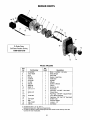
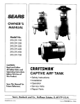
REPAIR
PARTS
2
3
18 1_
\
5
6
7
8
17
10
11
12
/
To Order Parts,
13
Call Sears Product Service,
1-800-366-7278
\
12
Model 390.2505
Key
No.
Part Number
Qty.
Used
Description
1#
2
3
4
5
6
7
8
9
10
11
J218-953C
17351-0009
N3-9
N20-35
U109-6A
J105-40P
L1-25P
N20-34
N32P-66
N34P-17
U111-211T
1
1
1
1
1
1
1
1
1
1
1
Motor - 115/230V - 60 Cycle
Water Slinger
Seal Plate
Gasket - Seal Plate
Shaft Seal
Impeller
Diffuser
Gasket - Diffuser
Venturi
Nozzle No. 43
Hose Barb
12"
13
N212-12P
2
1
Pipe Plug - 1/4" NPT - Hex Head
Check Valve
14"
15t
16"
17
18
19
20
N176-38A
U37-672P
2781
U36-112ZP
L43-5C
1
1
4
1
1
1
1
Pipe Plug - 1/8" NPT - Square Head
Pump Body Assembly
Capscrew - 3/8"-16x1-1/4" Hex Head
Switch Tube
Pressure Switch
Locknut - 1/2"
Connector
t
Includes Key Nos. 9, 10, 12, and 13.
* Standard hardware item. May be purchased locally.
# For repair or service to motors, always give the motor model number and any other data
found on the motor model plate.
]0
\
14
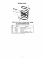
REPAIR PARTS
39
35
36
38
37
Shallow Well Jet Pump Air Volume Control
For Use With
Standard
Air
Package
Tanks
(Not Furnished - Must be purchased separately)
Key
No.
34
Part
Number
2761
Description
Air Volume Control
35
36*
37
U78-774P
U37-17GPT
U37-205P
Reducer Bushing - 1-1/4" x 1/4" NPT
Nipple - 1/4" x 1-1/2"
Tube - AVC
38
U111-86T
Compression
Fitting Elbow - 1/4" NPT
39
U111-100T
Compression
Fitting Straight - 1/8" NPT
* Standard hardware item. May be purchased locally.
]]
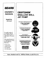
SEARS
OWNER'S
MANUAL
Model No.
390.2505
[RAFTSMAN*
SHALLOW WELL
JET PUMP
Forthe repair or replacementpartsyou need
Call7 am - 7 pm, 7 days a week
1-800-366-PART
(1-800-366-7278)
Forin-homemajorbrandrepair service
Call24 hours a day, 7 days a week
1-8OO-4-REPAIR
(1-800-473-7247)
The model number of
your Shallow Well Jet
Pump will be found on a
model plate on the pump
body.
When requesting service
or ordering parts, always
give the following
information:
• Product Type
• Model Number
• Part Number
• Part Description
Forthe location of a
SearsRepairService Centerin yourarea
Call24 hours a day,7 days a week
1-800-488-1222
Forinformationon purchasinga Sears
MaintenanceAgreementor to inquire
aboutan existingAgreement
call 9 am - 5 pm, Monday-Saturday
A
1-800-827-6655
SF.ARS
America's
Repair
Specialists
Sears, Roebuck and Co., Hoffman Estates, IL 60179
U.S.A.