1
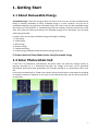
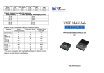
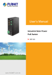
USER MANUAL PCL-1512/1524 SMART PWM SOLAR LIGHTING CONTROLLER V.2.0 WWW.MPPSOLAR.COM Table of Contents 1. GETTING START 1.1 ABOUT RENEWABLE ENERGY 1.2 SOLAR PHOTOVOLTAIC CELL 1.3 ACTIONS FOR OPERATION SAFETY 1.4 GLOSSARY 2. PRODUCT 2.1 PRODUCT FEATURES 2.2 CHECK YOUR PACKAGE CONTENTS 3. CONTROLLER INSTALLATION INSTRUCTIONS 3.1 CONTROLLER OVERVIEW 3.2 INSTALL YOUR CONTROLLER 3.3 RECOMMENDED USE OF THE CONNECTION WIRES 4. CONFIGURE YOUR CONTROLLER 4.1 SOFTWARE OVERVIEW 4.2 INSTALLATION AND SETUP 4.3 LIGHT TURN-ON MODES 4.4 INDICATORS ON THE CONTROLLER 4.5 RECOMMENDED SETTINGS FOR DIFFERENT BATTERIES 4.6 APPENDIX 3 3 3 4 5 8 8 9 10 10 11 12 13 13 14 18 18 19 20 2 1. Getting Start 1.1 About Renewable Energy “Renewable energy” means the energy of which the source never runs out. In order to enable human beings to develop sustainably on Earth, renewable energy is a must. However, only the use of renewable energy does not guarantee sustainable living. This is due to the fact that renewable energy will continue to cause pollution or manufacturing waste (for example, the heavy metal used in solar cells). Only when the waste generated by the renewable energy can be processed, can we indeed make living sustainable. Currently, there are six major renewable energy technologies, including: 1. Solar Energy 2. Hydro Energy 3. Wind Energy 4. Biomass Energy 5. Geothermal Energy 6. Ocean Energy (including the tidal and thermal energy conversion) To Protect the Earth, Please Make Greater Use of Renewable Energy 1.2 Solar Photovoltaic Cell A solar cell is a photovoltaic semiconductor thin panel which can utilize the sunlight directly to generate electricity. As it is illuminated with light, the voltage and current can be generated immediately. Such kind of solar photovoltaic cell is usually referred to as a photovoltaic cell or solar cell. In the early translated books in Taiwan, such a device is directly referred to as solar batteries according to the Kanji characters in Japanese. In fact, they are not batteries but cells, and can also be referred to as solar chips. 3 Silicon is known as “ ” (guei) in Mainland China because the character “ ” is an ancient Chinese ” (si) is a modern transliteration of “silicon”. word and “ In physics, such an energy conversion process is called “photovoltaic” (PV) (photo = light, voltaic = electricity). Silicon is a chemical element with a representative symbol “Si” in chemistry; it has an atomic number of 14; and it is a metal‐like element. A silicon atom has four electrons in the outmost orbit. Compared to carbon in the same column of the periodic table, silicon has a more stable chemical property. Silicon is the most common element, but rarely appears in its elemental form in nature. It usually exhibits a complex form of silicate or silica, which widely exists in rocks, gravel, and dirt. Silicon is the eighth abundant element in the universe. In the Earth’s crust, it is the second abundant element which makes up 25.7% of the total mass of the Earth’s crust, second only to the most abundant element oxygen (49.4%). In addition to the external dimensions, the specifications of photovoltaic (PV) panels include some characteristic data: ■ Voc = Open‐circuit voltage ■ Isc = Short circuit current ■ Vmp (Vop) = Maximum operating voltage ■ Imp (Iop) = Maximum operating current ■ Vmp x Imp = Watt / (Max) Power ■ Usually, the data shown in the brochure of a photovoltaic product are under the “international 2 standard light source condition”: 100mW/m ■ i.e., the solar illuminance at noon in an unclouded summer day which is 1.2 million LUX at the temperature of 25 degrees Celsius is used as the test condition. ■ For the different climate at different locations, the efficiency of the solar panel will be different. 1.3 Actions for Operation Safety All electronic and electrical operations must be carried out according to the local and/or international electrotechnical regulations or standards. Before installation or use of such device, please read this manual as well as the instructions and precautions for the controller, battery, solar panel and any other device. (Warning: The generic lead‐acid battery may produce explosive gas, and the short circuit of the positive and negative electrode of the battery may generate an electric current up to thousands of amperes.) Do not expose this product and the battery directly to the rain, snow or any type of liquid. For outdoor installation, it is recommended that it would be better to install the device in a box with proper ventilation. While connecting the PV panels or the batteries to the controller, do not cause short circuit; it may damage the normal functions of the controller. In order to reduce the possibility of short circuit, please use insulated tools during the installation or operation. During the installation operation, please take off watches, diamond rings, necklaces, jewelry, etc. so as to reduce the possibility of accidents. The system where the controller resides may contain several electrical circuits (batteries, solar panels, wind turbines, or mains power). Please carefully handle the electrical devices. 4 Before operation, please determine if the specifications of the PV panels and the lighting apparatus are within the proper operating range of the controller for solar charging and discharging. Do not attempt to repair this product. For any problems, please contact your local agent or dealer. 1.4 Glossary (LVD) Low Voltage Disconnection When the battery voltage is less than the value for low‐voltage disconnection, the controller will not supply to the load so as to protect the battery from over‐discharge. (LVR) Low Voltage Reconnection When the battery is under the condition of low voltage disconnection, if the battery voltage is recovered and higher than the value for low voltage reconnection, the low‐voltage circuit disconnection will be lifted and the connection is restored. (ACV) Absorption Charge Voltage When the battery voltage achieves the value of absorption charge voltage, the controller will maintain this voltage and charge for a period of time which will not cause excessive charging of the battery. (FCV) Float Charge Voltage When the battery charge completes the charging process, its voltage will drop to a float charge voltage and maintain at this voltage with a minimal charging current for supplemental battery charging. (PWM) Pulse Width Modulation There are many applications of PWM, such as motor control, servo control, light dimming, switched mode power supply, and even some audio amplifiers. In the DC motor control system, in order to reduce the current flowing through the motor coil and the power consumption, the pulse width modulation (PWM) is often used to control the on‐ and off‐time of the switched power component. Its most common application is to change the speed of the motor by changing the output pulse width or frequency. When the power supplied to the motor is controlled ON and OFF periodically at a fixed duty cycle, the longer the ON state takes, the faster the motor speed is; on the contrary, for a longer OFF state, the motor speed will be slower. This kind of motor speed control method by adjusting the ratio ON and OFF states is called pulse width modulation. The ratio of the ON state in a period is referred to as the duty cycle, expressed as a percentage. In this controller, the pulse‐width modulation is mainly achieved by using the MOS transistor to control the ON time of the power. By adjusting the pulse width, the target voltage can be achieved. When the 5 pulse width is wider, the output voltage is higher; on the contrary, when the pulse width is narrower, the output voltage becomes lower. Temperature compensation In order to protect the battery for a longer lifespan and achieve the fully‐charged condition of the battery, the charge voltage of the battery decreases with increasing temperature and vice versa. Accordingly, charging with a given voltage requires an increased charge current when the temperature is high and decreased charge current at a lower temperature. At temperatures below 5°C (41°F) or above 35°C (95°F), temperature compensation for charging voltage is necessary. Note: For the conditions under which the battery compensation function of the solar controller is activated, please refer to “Table of recommended settings for various battery types”. About Battery Batteries can be roughly categorized as “chemical” or “physical” batteries. Usually, the word “Battery” alone refers to a chemical battery. The device used to convert the energy generated through the oxidation and reduction reactions of some substances of its constituent materials into electrical energy is known as a chemical battery. On the contrary, the system which converts light and heat into electricity is known as a physical battery. Batteries, in general, can be categorized by different sizes, types, ampere‐hours, voltage, and chemicals. The basic guideline described below is helpful for selecting a battery. Because the batteries from different manufacturers have different operation requirements, you can configure the controller's battery parameters to ensure a longer lifespan of the battery. For the operating voltage setting of the battery, please contact your battery manufacturer. Batteries for Electrical Vehicle The batteries for the electrical cars and trucks are designed not for deep cycling but for high acceleration power. Please do not use this type of battery unless you have no other types of batteries to use. If this type of battery is use in the cycling system, it will be less durable and will be easily damaged. Maintenance‐ Free Batteries This type of battery is commonly used in cars or ships, but rarely used in PV systems. This type of battery is usually equipped with a reserved additional liquid electrolyte without the need of electrolyte replenishment, which is different from the sealed battery. Deep Cycle Batteries This type of battery is the most suitable for use in the solar system. They can have many different dimensions and formations. The most common is the non‐sealed electrolyte batteries. A non‐sealed lead‐acid battery has a cover which should be periodically removed for the visual confirmation of the level of the electrolyte. When the level of the electrolyte is too low, you may need to replenish it with distilled water under the fully‐charged condition. However, if the distilled water is added when the level of the electrolyte is too low but the battery is not fully charged, it may cause electrolyte overflow. Furthermore, only distilled water can be added into the electrolyte. If the water containing other impurities is added into the battery, it is very likely to reduce both the efficiency and the lifespan. 6 Sealed Batteries Another type of battery is sealed with rubber. This type of battery does not use the battery cover and the electrolyte is glue instead of liquid allowing the battery to be fixed at any location. This kind of battery has the advantages of no need to replenish the electrolyte for maintenance, a long life up to 800 cycling times, and a lower self‐discharge. This product mainly uses lead‐acid batteries. Other types can also be used such as nickel‐cadmium (Ni‐Cd), Ni‐MH, Lithium‐ion (Li‐ion) and other secondary batteries. Basically, lead‐acid batteries can be divided into two categories: one is flooded lead‐acid battery; the other is the sealed lead‐acid battery. Their differences are: the former will continuously produce gas which will be directly emitted from the battery during charging, so one must replenish water periodically; the latter is less efficient at its positive electrode during charging, so the oxygen produced in the earlier stage of charging will be used to suppress the production of hydrogen in the initial charging stage. In other words, the oxygen produced from the positive electrode during the charging process is absorbed directly and thus reacts with the surrounding electrolyte naturally so that the negative electrode is reduced back into lead sulfate, which is the original product during discharge. Because the sealed lead‐acid battery is intrinsically maintenance‐free, today's electrical vehicles use the latter as the lead‐acid batteries. Although lead‐acid batteries are not so ideal in power density and energy density and its lifespan is limited, the lead‐acid batteries are the mainstream batteries currently due to the low cost, better instantaneous discharge capacity, more mature development and technology, etc. This type of battery requires a higher voltage to charge the battery completely. While using this type of battery, please remember to set the related charging parameters through the software so as to maximize the benefits of the battery. Please contact the battery manufacturer to obtain the recommended setting values. 7 2. Product 2.1 Product Features When this product design is applied in an individual solar lighting system, it can optimize the turn‐on time of the street light, extend the lifespan of the lamp and the batteries, improve public security, and reduce the cost of street lights. This product can be used in outdoor lighting, electric power supply in remote areas, holiday flats, guest houses, bus stop shelters, signal lights, warning lights and communications equipment. Product Features: - Three light indication modes: Auto/Manual/Schedule - Automatic detection. When the turn‐on (off) condition is satisfied, the system will automatically turn on (off) the light. - Backward current protection: to prevent the current from flowing back to the PV panel. - Over‐current protection - Temperature compensation ‐ Over‐temperature protection ‐ Reverse polarity protection (for battery and charging electrodes) ‐ Three‐stage charging mode ‐ PWM voltage output control at the load ‐ Turn‐on test for the light ‐ Convenient LED indicators ‐ Automatic detection if the battery voltage is 12V or 24V. (Available in 24V system) ‐ Parameter settings can be configured through the computer. (RJ45/RS232 interface) ‐ Two‐year warranty of the product 8 2.2 Check Your Package Contents This product package contains the following items: 1. Controller x 1 2. User’s Manual x 1 3. CD‐ROM x 1 (containing the user’ manual and the utility) 4. RJ45‐to‐RS232 Cable x 1 *Temperature Compensation Cable x 1 (Optional) 9 3. Controller Installation Instructions 3.1 Controller Overview Solar Ll ighting Controller Control Panel I nstruc tion 10 3.2 Install Your Controller Please follow the following steps (sequence) to install the system: (1) Connect the temperature compensation cable (optional) and fix it at a location where the temperature is easily raised on the battery. (2) Set the DIP switches SW3 and SW4 to the OFF positions so that the controller will be operated in the Auto mode (please refer to Table 1 for the setting of the operation mode). (3) Connect the positive electrode of the battery to the terminal for the positive electrode of the battery on the controller. (4) Connect the negative electrode of the PV panel to the terminal for the negative electrode of the PV panel on the controller. (5) Connect the positive electrode to the terminal for the positive electrode of the PV panel on the controller. (7) Connect the negative electrode of the lighting apparatus to the negative terminal on the controller. (8) Connect the positive electrode of the lighting apparatus to the positive terminal on the controller. (9) Perform the test to confirm if the installation is completed. Please press the light turn‐on test button. The light turn‐on test button should not be pressed for more than 10 seconds. When the battery voltage is lower than LVD, the light turn‐on test is limited to be performed up to 5 times. 11 3.3 Recommended Use of the Connection Wires (Applicable to the system with a voltage attenuation less than 3%) The following table is applicable to the applications in the 12Vdc system. For the applications in 24Vdc system, the distance can be doubled. Distance in feet ( meters ) Amps 24 AWG 22 AWG 20 AWG 18 AWG 16 AWG 14 AWG 2.5 2.8 ft (0.85m) 4.4 ft (1.35m) 7.06 ft (2.15m) 11.25 ft (3.43 m) 18.0 ft (5.5m) 28.2 ft (8.61m) 5.0 1.40 ft (0.43m) 2.2 ft (0.68m) 3.53 ft (1.08m) 5.63 ft (1.71m) 9.0 ft (2.74m) 14.1 ft (4.3m) 7.5 0.93 ft (0.28m) 1.48 ft (0.45m) 2.35 ft (0.72m) 3.75 ft (1.14m) 6.0 ft (1.83m) 9.41 ft (2.87m) 10 0.70 ft (0.21m) 1.11ft (0.34m) 1.76 ft (0.54m) 2.81 ft (0.86m) 4.5 ft (1.37m) 7.06 ft (2.15m) 12.5 0.56 ft (0.17m) 0.89ft (0.27m) 1.41 ft (0.43m) 2.25 ft (0.69m) 3.6 ft (1.1m) 5.65 ft (1.72m) 15 0.47 ft (0.14m) 0.74 ft (0.23m) 1.18 ft (0.36m) 1.88 ft (0.57m) 3.0 ft (0.91m) 4.71 ft (1.43m) R1.3/2010 12 4. Configure Your Controller 4.1 Software Overview About the Solar Controller Utility: The “Solar Controller Utility” is a software tool provided for the user to configure the controller parameters so as to achieve the best application condition. Before the configuration operation, please contact the suppliers of your PV panel, lighting apparatus, and battery for the product‐specific parameters. Please use the Solar Controller Utility for the operation and configuration: (for generic lighting apparatus) Filename of the Installation Utility: Solar Charge Controller Install (SCC_Install_v8.01.exe) Filename of the Controller Configuration Utility: Solar Charge Controller Utility 13 4.2 Installation and Setup Install the Solar Controller Utility: Run the program "SCC_Install.Exe" in the CD‐ROM on the computer. Configure your Solar Controller: Step 1: Under "Start"‐> Programs ‐> All Programs ‐> "Solar Charge Controller", select "Solar Charge Controller Utility" (please refer to the following figure). Step 2: Configure your controller, please refer to the following descriptions for each button and related functions: 14 Toolbar on the top: 1. Open: Open the existing controller parameter file in the computer. 2. Save: Convert the controller parameters into a file and store it in the personal computer. 3. Link PC: Set the serial port of the computer to connect to the controller. * Use the “automatic detection” function or manually select the required serial port and then click “OK” to confirm the setting. * If the connection between the controller and the computer has failed, the user is not able to read or change the parameter settings in the controller. 4. Default: Restore the parameter settings to the factory default. 5. Help: Message for the software version. 6. Last Set: Restore the current parameter settings in the utility to the previously used parameter values. 7. New Set: Load the current parameter settings in the utility into the controller. 8. Exit: Exit the utility. 15 Description of the Related Setting Items: Low Voltage Disconnection and Low Voltage Reconnection: When the battery voltage is lower than the value for the low‐voltage disconnection (LVD), the controller will stop supplying power to the load. It requires the charging from the PV panel so as to increase the battery voltage to be above the value for low‐voltage reconnection (LVR) and thus the turn‐on and turn‐off operations of the light can be recovered. Absorption Voltage and Float Charging Voltage: According to the characteristics of the battery, the user can set the required charging voltage. The absorption charging will last for 60 minutes. Number of Charge Times: When the battery voltage is lower than LVD, the battery will be charged through the PV panel. After the battery voltage is higher than LVR, the battery operation is recovered and the number of charging times is increased by +1. Load Voltage Setting: Set the maximum and minimum voltages required for the lighting apparatus so as to determine the PWM output voltage (Max. Voltage‐Min. Voltage) * Percentage + Min. Voltage = Output Voltage. PV Panel Voltage: In the Auto/Manual modes, the turn‐on and turn‐off times are determined by the PV panel voltage. This voltage value can be adjusted according to the demand. (Note: Both the turn‐on and turn‐off operations will be performed with a 1‐minute delay.) Pulse Width Modulation (PWM) Control: When this function is enabled, the brightness of the light can be adjusted (0%~100%). If it is disabled, only the brightness values 0% and 100% can be used. Brightness: Set the output signal with proper PWM duty ratio between the maximum brightness (100%) and the minimum brightness (0%). Temperature compensation: According to the battery type, the temperature compensation coefficient and the over‐temperature protection function will be determined. Auto/Manual Output: Set the time interval for each stage and its corresponding brightness in the Auto/Manual modes. 16 In the Auto mode, after the light is turned on, the brightness of the light will be controlled in the sequence of 1 >2 >3 >4 >5 >6 >7 >8 >1 >2>...and then continue the sequence till the PV panel voltage satisfies the turn‐off condition to turn off the light. In the Manual mode. The overall turn‐on time is set as 10 hours. After the light is turned on, the brightness of the light will be controlled in the sequence of 1 >2 >3 >4 >5 >6 >7 >8 >1 >2> till the preset time of 10 hour for turning off the light. During the operation, if the PV panel voltage satisfies the turn‐off condition, the light will also be turned off. Scheduled Output: Use the left mouse button to drag the required light turn‐on schedule under the timing table. After clicking the schedule, it is allowed to modify the output brightness and turn‐on time on the top column. Up to 8 scheduled stages of turn‐on times can be configured. Delete Schedule: Delete the selected schedule settings in the schedule mode of the software. Note: After the required settings are configured, please remember to update them into the controller (click the “Update New Settings” button). 17 4.3 Light Turn-on Modes The solar controller series charging/discharging controller provide the following modes: (1) Auto Mode: Use the voltage detection function of the PV panel. If the voltage is lower than the turn‐on voltage then the light is turned on; if the voltage is higher than the turn‐off voltage then the light is turned off. The voltage parameter setting can be changed by using the utility. (2) Manual Mode: Use the voltage detection function of the PV panel. If the voltage is lower than the turn‐on voltage then the light is turned on; if the voltage is higher than the turn‐off voltage then the light is turned off. The voltage parameter setting can be changed by using the utility. Meanwhile, the turn‐on time of the light can be configured as 6/8/10/12 hours. (Please refer to the time schedule table for timing control). Example: When the turn‐on time is set as 8 hours, after the light is turned on, if the voltage of the PV panel is higher than the turn‐off voltage then the light is turned off; if the voltage of the PV panel is not higher than the turn‐off voltage then the light will remain turned on up to 8 hours. (3) Software Schedule Mode: The turn‐on or turn‐off operation is carried out according to the timer count of the internal real‐time clock. Up to 8 stages of timing schedules can be used. * For the parameter settings, please refer to the descriptions in “Installation and Setup”. 4.4 Indicators on the Controller State of LED Indicators: System On Charging LVD Bad Batt. Over‐current Short‐circuit PV disconnect LED Color Green Green Red Red Red Remark On: 2.0 sec Off: 2.0 sec On: 0.5 sec Off: 0.5 sec On: 0.5 sec Off: 0.5 sec On On: 2.0 sec Off: 2.0 sec 18 4.5 Recommended Settings for Different Batteries Description Specification Battery type Nickel-cadmium Battery System Model 12V 24V Maximum input voltage DC 22.5 V DC 45 V Output voltage for Load Equal to battery’s voltage Equal to battery’s voltage Float charge voltage DC 13.6V ( 13.0~15.0V) DC 27.2V ( 26.0~30.0V ) Absorption charge voltage DC 14.6V ( 14.0~16.0V) DC 29.2V (28.0~32.0V) LVD(Low Voltage Disconnection) DC 11.1V (10.5~12.5V ) DC 22.2V (21.0~25.0V ) LVR(Low Voltage Reconnection) DC 12.4V (11.5~13.5V ) DC 24.8V (23.0~27.0V ) Temperature compensation Beseline@25°C +-20 mV/°C for NiCad type batteries, Charge cut-off @ 55°C +-40 mV/°C for NiCad type batteries, Charge cut-off @ 55°C Battery type Lead-acid batteries (Default Setting) System Model 12V 24V Maximum input voltage DC 22.5 V DC 45 V Output voltage for Load Equal to battery’s voltage Equal to battery’s voltage Float charge voltage DC 13.6V ( 13.0~15.0V) DC 27.2V ( 26.0~30.0V ) Absorption charge voltage DC 14.6V ( 14.0~16.0V) DC 29.2V (28.0~32.0V) LVD(Low Voltage Disconnection) DC 11.1V (10.5~12.5V ) DC 22.2V (21.0~25.0V ) LVR(Low Voltage Reconnection) DC 12.4V (11.5~13.5V ) DC 24.8V (23.0~27.0V ) Temperature compensation Beseline@25°C +-30 mV/°C for lead acid type batteries, Charge cut-off @ 55°C +-60 mV/°C for lead acid type batteries, Charge cut-off @ 55°C System Specifications Temperature sensor cable (Optional) 1m, Operating temperature range of TS cable from -20°C to 55°C, Storage temperature from -40°C to 90°C Operating temperature -20°C ~ 60°C Storage temperature -40°C ~ 90°C Operating humidity 20% ~ 80% Maximum charging current 15A Maximum output current 15A Dimensions 182x82.6x38.3mm RJ45/RS232 Cable 1.8m Compact disc Solar Application Controller Utility w/User’s manual and a QIG. 19 4.6 Appendix Problem Inspection Procedure For the initial installation, 1. Please make sure that all the wires connected to the all the green LED indictors battery are connected with the correct polarity and all the wires are fixed tightly. are not lit. 2. Please check if the battery is in the usable condition. (If the voltage is lower than 6V, the controller cannot be operated.) After a long time of use, the green LED indicators are not lit. 1. Please check if the wires are loosened or broken. 2. Please check if the batter is in the usable condition or please replace it with a new battery. On sunny days, the green charging LED indicator is not blinking quickly (turned on for 0.5 sec and turned off for 0.5 sec). 1. Please check if the PV panel is covered by snow or dust, or shadowed by the nearby object so that the voltage is lower than the battery voltage and thus the battery cannot be charged normally. 2. The wire connection of the PV panel falls off. The schedule output setting fails. 1. Please check if the real‐time clock of the controller is configured with correct time settings. 2. Please check if the battery voltage is lower than LVD. 3. Please check if the controller has a correct voltage output. The lighting apparatus is not lit during the light turn‐on test. 1. Please check if the wire connection between this product and the lighting apparatus is connected properly without loosening or bad contact. 2. Check if the lighting apparatus is usable. The light turn‐on test is not responding. Under the LVD condition, the light turn‐on test can be performed only 5 times at most. The red LED indicator is lit. Several conditions will cause the LED to be lit constantly: 1. Battery damage: Please check if the wire connected between this product and the battery falls off or the battery must be replaced; 2. Over‐current: Please check the current specifications of the PV panel or the port. Do not exceed the rated current of the solar controller. If the current exceed the rated current of the solar controller, please replace with PV panel or the port which complies with the specifications. After the replacement, press the Reset button for more 20 than 10 sec so as to allow the controller to perform the system reset operation. 3. Short circuit: Please check if the wires or connects at the terminals are loosened, broken, or blown out. Please make sure that no fallen wire contacts other terminals or wires to cause short circuit. If the cause of short circuit is found and removed, please fasten the screws at the terminals and then press the Reset button for more than 10 sec so as to allow the controller to perform the system reset operation. Night power‐source‐free output (Auto/Manual modes) 1. Please check if the LVD indicator is blinking? (quick blinking of the red LED indicator) 2. If not, please press the “Light Turn‐on Test” button to make sure if the voltage output is correct. 3. If the voltage output is correct, please check if the wires at the output terminals are loosened. * If the battery voltage is lower than 18V, it can be used as a 12V battery system; if the battery voltage is not lower than 18V, it can be used as a 24V battery system. * For a 12V battery, if the battery voltage is not higher than 8V, it should be regarded as an unusable battery. 21