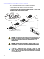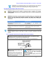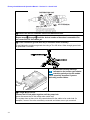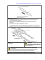
1
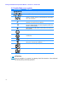
Enecsys Enables OPTIMAL SOLAR SOLUTIONS intelligent reliable power Enecsys Installation and Operation Guide Enecsys Micro inverters Enecsys Gateway Enecsys Repeater Enecsys Double Repeater Document Number: IOG010212 Version: 1.6 June 6, 2012 www.enecsys.com Enecsys Installation and Operation Manual – Version 1.6 –June 6 2012 Table of Contents 1 Important Safety Instructions 4 1.1 Audience 1.2 Products covered by this manual 1.3 Conventions used in this manual 1.4 Safety 1.5 Installation compliance requirements 1.6 Installation safety instructions 1.7 System installation best practices 4 4 5 5 7 8 9 2 Installation Sequence 10 2.1 Customer site inspection 2.1.1 Installation assumptions 2.1.2 Site requirements for Enecsys micro inverters and monitoring system 2.2 Install the Enecsys gateway 2.3 Test the communications between micro inverters and gateway 2.4 Mount the Enecsys micro inverters and cable harness 2.5 Inspect and test the AC cabling before it is connected to the mains utility grid 2.6 Connect the micro inverters, AC bus cabling, and ground wire 2.7 Connect the DC cables from the PV modules to the micro inverters 2.8 Connect the AC cabling to the mains utility grid 2.9 Set up the new installation on the Enecsys monitoring website 2.10 Finalize installation and user details; launch the installation 10 10 10 10 11 11 11 11 11 11 12 12 3 Installing the Gateway 13 3.1 Mounting the gateway 3.2 Connecting the gateway 3.2.1 Switching User and Installer modes 14 15 15 4 Using the Enecsys Gateway 16 4.1 Checking communication between the gateway and the micro inverters 4.1.1 Gateway User Mode screen 4.1.2 Switching to Installer Mode 4.1.3 Gateway installer mode screen 4.1.4 Communication connection quality symbols 4.1.5 Installer Mode screen symbols 16 16 16 17 17 18 5 Using Enecsys Repeaters 19 5.1 Failure to establish reliable communications 5.2 Using single repeaters 5.3 Using the double repeater with external antenna 5.4 Installing one or more single repeaters 5.4.1 Mounting the single repeater 5.4.2 Connecting the single repeater 19 19 20 21 22 22 2 Enecsys Installation and Operation Manual – Version 1.6 –June 6 2012 5.5 Installing a double repeater 5.5.1 Mounting the double repeater 5.5.2 Mounting the external antenna 5.5.3 Connecting the double repeater 23 23 24 24 6 Installing the micro inverters 26 6.1 Single micro inverter 6.2 Mounting the single micro inverter 6.3 Duo micro inverter 6.4 Mounting the duo micro inverter 6.5 Installing and connecting the AC bus cabling, single and duo 6.5.1 Branch cables and distribution units 6.6 Connecting the single or duo micro inverter 6.6.1 Connection Instructions for single and duo micro inverters 6.6.2 Disconnecting a micro inverter 6.7 Micro inverter technical details 26 28 29 32 33 33 35 35 38 38 7 Monitoring Setup and Installation Launch 39 7.0 Installer login 7.1 Adding a new installation Step 1: Input the installation owner’s details. Step 2: Enter installation site details. Step 3: Input the system information. Step 4: Add gateway serial number(s). Step 5: Begin layout by adding a section. Step 6: Enter section details. Step 7: Adjust section layout. 7.2 Installation finalization and launch Step 1: Find the pending installation Step 2: Drag-and-drop inverter serial numbers Step 3: Check work and launch installation Step 4: Inform the customer 39 39 39 39 40 40 41 41 42 44 44 44 45 46 8 Troubleshooting 47 8.1 Communication 8.2 Monitoring 47 47 9 Product return process 48 9.1 For the end user 9.2 For the customer (installer or distributor) 48 48 10 PV module / micro inverter serial number form 49 3 Enecsys Installation and Operation Manual – Version 1.6 –June 6 2012 1 Important Safety Instructions SAVE THESE INSTRUCTIONS – This manual contains important instructions that must be followed during installation and maintenance of all the micro inverters covered in the manual. 1.1 Audience This manual is intended for installers and electricians involved in the installation and set up of Enecsys Solar micro inverter systems. It is expected that installers will have knowledge of the necessary steps needed for safe and successful installation of Enecsys micro inverters and associated apparatus. Electricians must have knowledge of the electrical codes and regulations of their specific country as well as safe methods of practice. Installers can view the Enecsys installation video on the website: http://enecsys.com/resources/videos.php 1.2 Products covered by this manual This manual covers the following products: SMI-S200W-60 micro inverter (certified as part number: SMI-200-60) SMI-S217W-60 micro inverter (certified as part number: SMI-217-60) SMI-S240W-60 micro inverter (certified as part number: SMI-240-60) SMI-S200W-72 micro inverter (certified as part number: SMI-200-72) SMI-S240W-72 micro inverter (certified as part number: SMI-240-72) SMI-S263W-72 micro inverter (certified as part number: SMI-263-72) SMI-D360W-72 duo micro inverter (certified as part number: SMI-360-72) SMI-D480W-60 duo micro inverter (certified as part number: SMI-480-60) Gateway Single Repeater Double Repeater Monitoring software 4 Enecsys Installation and Operation Manual – Version 1.6 –June 6 2012 1.3 Conventions used in this manual The following conventions are used throughout this manual. These conventions should be noted and followed at all times. WARNING Warning statements must be heeded at all times. A warning symbol indicates that a process or instrument has the potential to harm or cause lethal injury if the correct method of handling is not employed. CAUTION Caution statements are used to indicate where a part of the installation process may have the potential to damage equipment. Caution statements should be followed at all times. ATTENTION Attention statements are used to indicate where a part of the process or instrument has a special requirement. Attention statements should be followed at all times. 1.4 Safety Before installing and using any Enecsys micro inverter please ensure that you have fully read and understand all of the installation instructions and heed all warnings and cautions given. WARNING The installation and/or replacement of Enecsys micro inverters must only be carried out by qualified professionals. WARNING All electrical installations should be performed in accordance with all local and national electrical installation codes and practice. WARNING All electrical connectors must be dry before making any connections and must be kept dry during the installation process. WARNING Lightning protection To avoid voltages being induced by lightning, the roof-mounted wiring must be arranged as radial branches, or as a single branch. Wiring loops or rings must not be used. Further independent active protection against lightning strike may be required, to local and national standards. 5 Enecsys Installation and Operation Manual – Version 1.6 –June 6 2012 WARNING Isolation of the AC cabling The AC wiring from the inverters must have provision for electrical isolation from the grid mains supply (for example, by using a circuit breaker), so that inspection, fault detection, testing, maintenance and repair can be performed. WARNING Never disconnect any Photovoltaic module from an Enecsys micro inverter without first isolating the AC mains. WARNING The inverter and metalwork must be earthed/grounded in accordance with national and local electrical standards. WARNING Enecsys micro inverters, gateways and repeaters contain no userserviceable parts. Do not attempt to open or repair. Opening or tampering with the Enecsys micro inverter, gateway or repeater will void the warranty. • If your micro inverter(s) fail(s), contact your installer company or the Enecsys help desk. • New units with damage must not be installed: return them to the supplier. WARNING If either the gateway or the repeater/double repeater exhibit any of the following characteristics unplug the products from the mains electrical supply. Contact either your distributor or installation company. - The power supply or its plug is damaged. - If liquid has been spilled into the product. - The product has been exposed to rain or water. - If the product does not operate properly. - If the product has been dropped or damaged in any way. - If there are noticeable signs of overheating CAUTION The Aluminum body of the Enecsys micro inverter serves as the heat sink for the unit and as such can reach temperatures of 70oC. The Enecsys micro inverter should not be touched while in operation. 6 Enecsys Installation and Operation Manual – Version 1.6 –June 6 2012 ATTENTION: Protection on the AC wiring Further protection on the AC wiring from the inverters must be provided and may be required by local and national wiring Regulations. This protection is likely to include Residual Current Devices, Earth Fault Monitors and/or Circuit Breakers. This product can cause current with a DC component. Where a residual current-operated protective (RCD) or monitoring (RCM) device is used for protection in case of direct or indirect contact, only an RCD or RCM of Type B is allowed on the supply side of this product. ATTENTION: Voltage drop across the AC wiring To ensure that the system is operating efficiently, the voltage drop across the AC wiring should be measured. This is best done by direct measurement, but can be arrived at by calculations, graphs or tables. ATTENTION: Installation Testing: Initial verification Before being connected to the grid mains supply, the wiring installation must be inspected and tested to verify that the requirements of the regulations have been met. The type and level of the tests must be in accordance with the local and national regulations. Suitably qualified persons must carry out the tests and the interpretation of the results. ATTENTION The inverter handle is not designed to support weight in excess of thirty pounds (13.6kg) of static pressure. Do not stand on, or place excessive weight on, Enecsys inverters. ATTENTION The gateway and repeater/double repeater are intended for stationary indoor use only. - Do not mount in a location where they will be exposed to direct/excessive solar and/or heat radiation. - Do not expose to heat-trap conditions or to water condensation. - Do not use liquid or aerosol cleaners when cleaning: clean only with a damp cloth. - Do not use near water. - Transition of these items between temperature extremes may cause condensation on some of the internal parts. If you notice condensation on or behind the product’s display window, allow it to dry naturally before re-connecting to the main electrical supply. 1.5 Installation compliance requirements • The Installation must be wired in accordance with the regulations in force in the country where the micro inverters are to be deployed. For example: For the UK: IEE Wiring Regulations, BS 7671, latest edition 7 Enecsys Installation and Operation Manual – Version 1.6 –June 6 2012 For the USA: National Electrical Code, ANSI NFPA 70 For Canada: Canadian Electrical Code, Part 1 • For UL 1741 compliant Installations: The system shall not be aggregated above 30kW on a point of common connection. The inverters must always be installed on a branch circuit with a 2P + 1P external transient voltage surge arrestor. The external device must meet IEC 61643-1 class II requirements. • For AS 4777 compliant installations: The inverters must always be installed on a branch circuit with a 2P + 1P external transient voltage surge arrestor. The external device must meet IEC 61643-1 class II requirements. • All Canadian installations must comply and be in accordance with the Canadian Electrical Code, Part 1. Input and output circuits of the inverters must be isolated from the enclosure. • For VDE 4105 compliance, installations are limited in size to 3.68kVA. • In jurisdictions that require it, a location-specific disconnect (such as an ENS box) must be part of the installation. • For compliance with NEC code, please note: WARNING: The Enecsys micro inverter, gateway, and monitoring components work in conjunction to report faults. For NEC compliance, do not install the PV system without the micro inverter, gateway, and monitoring components in place. 1.6 Installation safety instructions • The Enecsys micro inverters are provided with fixed trip limits for both voltage and frequency. • The External Earth connection screw shall be torqued to 6Nm +/- 10%. • The system grounding is the responsibility of the installer. WARNING: Whenever the PV module is exposed to light, it supplies a DC voltage. Follow all safety instructions and warnings provided by the module manufacturer’s documentation. WARNING: Power fed from more than one source. WARNING: The micro inverters, gateway and repeaters contain no user serviceable parts and must be returned to the supplier in the case of damage. Micro inverters with damage to integrated power supply cords should not be installed or serviced: they must be returned to the supplier. 8 Enecsys Installation and Operation Manual – Version 1.6 –June 6 2012 WARNING: Do not connect this or any other Enecsys micro inverter to an external battery. WARNING: During normal use, the case temperature of the micro inverter can exceed 70°C. Install it such that casual contact with the unit is prevented. WARNING: if connections are not made in the correct order, a voltage may be present at the exposed wires on the grid connect cable. The bare wire end of the grid connection cable of each branch circuit should be connected first to the AC system per the installation instructions. For installation instructions, see “6 Installing the micro inverters”. CAUTION: To reduce the risk of fire, connect only to a circuit provided with 16 amperes maximum branch-circuit overcurrent protection (20A breaker, 16A continuous rating) in accordance with the National Electrical Code, ANSI/NFPA 70. 1.7 System installation best practices • Be aware of the anodic index of dissimilar metals used in the installation process. Note that graphite is a metal. • Components used to install the PV array should be rated for array conditions and anticipated installation life. 9 Enecsys Installation and Operation Manual – Version 1.6 –June 6 2012 2 Installation Sequence 2.1 Customer site inspection CAUTION: All work carried out at a customer site must follow the health and safety instructions for working at height for the country in which the system is installed. (For example, in the UK, this is laid down in the Work at Height Regulations 2005. In the US, there are OSHA standards for Fall Protection.) 2.1.1 Installation assumptions • The PV system has been at least partially planned at the point when micro inverters are being considered. The number of PV panels will determine the number of micro inverters needed. The voltage characteristics of the modules chosen will determine the Enecsys micro inverter to use. The PV panel characteristics should match the micro inverter model chosen, and the PV panel layout should be finalized. • Approximate yearly energy yield is calculated when the micro inverters will be set up on the Enecsys monitoring system. This figure must be entered when the monitoring is set up. • Installation plan has taken inverter positioning and cabling configuration into account. • Permits and certifications must be in place before installation. • Racking systems vary by PV installation. The installer should use a method of mounting the micro inverters that works with the racking system. Installers must supply their own mounting hardware. 2.1.2 Site requirements for Enecsys micro inverters and monitoring system • The customer must have a broadband Internet connection. • There must be an unused Ethernet port on the customer’s router to connect to the Enecsys gateway so the gateway can communicate with the online monitoring system. The information provided by the Enecsys gateway is used to troubleshoot the installation as it progresses. • If the roof is made of metal or lined with metal foil, it may be necessary to install a double repeater right below it, in a loft or attic, for example. The double repeater connects to a remote antenna that is installed on the roof above the metal surface, where it can communicate with the micro inverters and the Enecsys gateway. • If a repeater or double repeater is necessary, there must be power outlets in the required locations. 2.2 Install the Enecsys gateway At the earliest possible stage during the onsite installation, the installer should connect the Enecsys gateway to the customer’s router using the Ethernet cable provided. When the gateway is powered up, it will be ready to start monitoring the micro inverters as soon as they are connected to the PV panels on an individual basis. (See “3 Installing the Gateway”.) 10 Enecsys Installation and Operation Manual – Version 1.6 –June 6 2012 Q: Why is it recommended to set up the gateway as early as possible during the installation? A: Once the gateway is functioning it will show which individual inverters have DC connections, even without AC power to the inverters. Solving connection issues before finalization can help the installation to proceed more efficiently. 2.3 Test the communications between micro inverters and gateway By looking at the “Installer Mode” screen on the gateway unit, the installer can see if the gateway is receiving a good signal from all of the micro inverters. See section 4 “Using the Enecsys Gateway”. If communications have not been established, it may be necessary to install one or more repeaters. See section 5 “Using the Enecsys Repeaters”. 2.4 Mount the Enecsys micro inverters and cable harness The installer must follow the installation design, mount all the micro inverters on the racking/mounting system, prepare the roof penetration conduit and lay the AC branch bus cabling. Note that the micro inverters must not be connected at this point. • The single micro inverters must be installed with the round plastic antenna covers facing downwards towards the roof. • See “6.2 Mounting the single micro inverter” or “6.4 Mounting the duo micro inverter”. 2.5 Inspect and test the AC cabling before it is connected to the mains utility grid When all of the AC cabling is in place, but before it is connected to the grid, it must be inspected and tested to verify compliance with the relevant electrical installation standards. 2.6 Connect the micro inverters, AC bus cabling, and ground wire See “6.5 Installing and connecting the AC bus cabling, Single and Duo” and “6.6.1, Connection instructions for the Single and Duo micro inverters”, steps 1 through 4. Install the ground wire (if applicable). 2.7 Connect the DC cables from the PV modules to the micro inverters See “6.6 1, Connecting the single or duo micro inverter”: step 5. When the PV modules are connected to the micro inverters, they will immediately start communicating with the Enecsys gateway. 2.8 Connect the AC cabling to the mains utility grid See “6.6 1, Connecting the single or duo micro inverter”: step 6. WARNING Connection of the AC cable to the mains utility grid must only be done by a qualified electrician. 11 Enecsys Installation and Operation Manual – Version 1.6 –June 6 2012 2.9 Set up the new installation on the Enecsys monitoring website WARNING: The Enecsys micro inverter, gateway, and monitoring components work in conjunction to report faults. For NEC compliance, do not install the PV system without the micro inverter, gateway, and monitoring components in place. o o If the installer has not worked with Enecsys micro inverters before, it’s time to set up an Installer Account. For setup details, see section 7.0, “Installer Login”. Before installing the gateway, the installer should log onto the Enecsys Monitoring website with his installer account and set up the individual installation. The installer will need details such as the homeowner's name and email address, street address of site, estimated yearly energy production, and average cost of electricity per kilowatt-hour. 2.10 Finalize installation and user details; launch the installation • 12 See section 7, “Monitoring Setup and Installation Launch”. Enecsys Installation and Operation Manual – Version 1.6 –June 6 2012 3 Installing the Gateway • The gateway is connected to the Internet using an Ethernet port on the customer’s router. • It communicates with the micro inverters so the PV installation can be monitored using an Internet browser. It has a screen, shown below, which will be used later in the installation to check communication with the micro inverters. • It must be installed indoors near a power outlet for the plug. Gateway Display: Installer Mode 13 Enecsys Installation and Operation Manual – Version 1.6 –June 6 2012 CAUTION: the gateway must only be used with the antenna that is already fitted to it. It must NEVER be connected directly to an external antenna mounted on the roof of the building or anywhere else, as it has no surge protection from lightning. If you need to use an external antenna then you must install a double repeater. See section 5, “Using Enecsys Repeaters”. Plug-top adapter Ethernet Cable Gateway scope of delivery: • 1 Enecsys gateway. • 1 Plug-top mains adapter – 5V DC 1A. • 1 Ethernet cable – length 2m. 3.1 Mounting the gateway 14 • The gateway must be installed indoors near a mains power socket. • It can be freestanding, either upright as shown in the illustration, or laid flat on its plastic feet. • It can be wall mounted using two screws in the position shown in the diagram. • It can be mounted using sticky pads in the position shown in the diagram below. Enecsys Installation and Operation Manual – Version 1.6 –June 6 2012 3.2 Connecting the gateway • • The Enecsys gateway requires the following connections: o 5V DC power input from the plug-top power supply. o Ethernet connection to the customer’s router. When the DC power adapter is switched on at the mains, the Enecsys gateway will power up immediately and its screen will display the “User Mode” screen. To enter installation information, the gateway needs to be in Installer Mode. After the installation is complete, switch back into User Mode. 3.2.1 Switching User and Installer modes Connect one end of the supplied Ethernet cable to a spare Ethernet port on the rear of the customer’s router. Connect the other end of the supplied Ethernet cable to the Ethernet port on the left hand side of the Enecsys gateway. Connect the supplied 5V DC plug-top power adapter jack to the 5V DC-in power socket on the left hand side of the Enecsys gateway. Connect the 5V DC plug-top power adapter to a mains power source. The gateway will power up immediately in User Mode. To access the Installer Mode screen: insert the sharp end of a pencil or a straightened paper clip into the Installer Mode recess on the left hand side of the Enecsys gateway for approximately 5 seconds. To return to the User Mode screen: press on the Installer Mode button for a short period. Once installed, do not disconnect or move a gateway. This may interfere with the transmission of data resulting in incorrect values being displayed on the monitoring site. 15 Enecsys Installation and Operation Manual – Version 1.6 –June 6 2012 4 Using the Enecsys Gateway The gateway should already be installed: see Section 3, “Installing the Gateway”. 4.1 Checking communication between the gateway and the micro inverters The gateway default display is User Mode. During routine operation, this screen shows enough information for the user to see that the inverters are operating and reporting to the monitoring system. • Gateway IP address. • The number of micro inverters communicating. • Overall communication status: server, communications link, and power. • Basic connection status details display in User Mode. Switch to Installer Mode for more communication connection quality information: see “Switching to Installer Mode”. 4.1.1 Gateway User Mode screen User Mode Display Description Status Number of Online Inverters: “0” (zero) is the number displayed. There is no communication between the gateway and inverters. Number of Online Inverters Number displayed equals the number of inverters plus the number of repeaters. Communication is good and connections are properly made. Number of Online Inverters Number displayed does not equal the number of inverters plus the number of repeaters. Possible malfunction or connection problem. User should contact the installer. Installer may need to test connections. If possible, troubleshoot via the Enecsys Monitoring Site. 4.1.2 Switching to Installer Mode Switching to Installer Mode shows more details technical details such as communication link quality and gateway server IP address. • 16 The Installer Mode switch is very small, and is located just above the Ethernet connector. Enecsys Installation and Operation Manual – Version 1.6 –June 6 2012 • To select Installer Mode, press the Installer Mode switch with the sharp end of a pencil or a straightened paper clip, and keep it pressed for 5 seconds. • To return to User Mode: o press the Installer Mode switch again just briefly, or o disconnect the gateway from its power source, then power up again. 4.1.3 Gateway installer mode screen 4.1.4 Communication connection quality symbols Symbol • Description Status and Action X Weak communication link Install one or more repeaters. ? Medium communication link If possible, reposition the Enecsys gateway to a higher position in the building. If a check P cannot be established then install a repeater. P Strong communication link No action is needed. In Installer Mode, the check P symbol should display in the Communication Connection Quality Field. If the “?” or X symbol are displaying, it may be necessary to one or more repeaters: see section 5, “Using Enecsys Repeaters”. 17 Enecsys Installation and Operation Manual – Version 1.6 –June 6 2012 4.1.5 Installer Mode screen symbols Screen Symbol Description “ENECSYS” is always displayed. Enecsys gateway IP address. Gateway server IP address. Number must be equal to the total number of inverters and repeaters installed. If 0 displays, there is no communication link. If the number is low, test connections. Communication link quality: a reliable communication link has been established. This symbol must be displayed. Communication link quality: the communication link is not good enough for reliable operation. Try moving the gateway nearer to the inverters, or install a repeater. Communication link quality: Weak communication link. Install one or more repeaters. The gateway is connected to the internet. The gateway is not connected to the internet and must be checked for malfunction. The power source is connected. Communication link status: flashing when trying to establish a link, steady when a link has been established. Connection to server: the gateway is connected to the server. Connection to server: the gateway is not connected to the server. ATTENTION After the installation is complete, the gateway should be returned to User mode and left that way during customary operation. 18 Enecsys Installation and Operation Manual – Version 1.6 –June 6 2012 5 Using Enecsys Repeaters The Enecsys gateway receives signals from the micro inverters on the roof and broadcasts the data over the Internet to the Enecsys Monitoring server. If the gateway cannot receive strong enough signals from micro inverters, a repeater installed nearer the PV modules on the roof will receive the signals, boost them, and then relay them to the gateway. In some cases it may be necessary to install more than one single repeater to boost signals two or more times before they reach the gateway. 5.1 Failure to establish reliable communications • If the Enecsys gateway displays the check symbol “P“ on the Installer Mode screen, communications link between the gateway and the inverters is established and is reliable. • If the gateway displays either the “?” or “X” symbol, the communications link may not be strong enough to be reliable. It may be necessary to: o o Install one or more single repeaters. See section 5.4, “Installing a Single Repeater.” Install a double repeater. See section 5.5, “Installing a Double Repeater”. 5.2 Using single repeaters • If the “X” symbol is displayed on the gateway Installer Mode communication status, one or more Enecsys single repeaters can be used. Start with one and observe for the “X” to change to a “P“. • If the “?” symbol is displayed, signal quality is poor. Distance between the inverters and gateway may be the problem: installing a second single repeater may help. • The diagram shows a building with two single repeaters between the PV modules on the roof and the Enecsys gateway on the ground floor. 19 Enecsys Installation and Operation Manual – Version 1.6 –June 6 2012 5.3 Using the double repeater with external antenna Even with a single repeater installed in the installation space, it may not be possible for the gateway to receive signal from the micro inverters. This can happen for the following reasons: • The roof may be made out of metal, or be lined with metal foil. • The distance between the micro inverters and the single repeater or gateway may be too great. • The building may have UV-screened windows. In this case, it is necessary to install a double repeater with external antenna. The external antenna must be mounted on the roof above any metal roof layers. It is connected to the double repeater inside the building by a coaxial cable. The double repeater passes the inverter signals via its normal internal antenna to the Enecsys gateway. 20 Enecsys Installation and Operation Manual – Version 1.6 –June 6 2012 5.4 Installing one or more single repeaters The single repeater should ideally be installed in the roof space, directly below the micro inverters. It must be installed near a mains power socket for the plug-top mains adapter. If you need to install a second single repeater, this should be located on one of the intermediate floors between the repeater in the roof space and the Enecsys gateway on the ground floor, as shown in the diagram in section 5.2 “Using Single Repeaters”. Single repeater scope of delivery: • 1 Single repeater unit. • 1 Plug-top mains adapter – 5V DC 1A. 21 Enecsys Installation and Operation Manual – Version 1.6 –June 6 2012 5.4.1 Mounting the single repeater • The single repeater must be installed indoors near a mains power socket. • It can be freestanding, either upright as shown in the illustration, or laid flat on its plastic feet. • It can be wall mounted using two screws in the position shown in the diagram. • It can be mounted using sticky pads in the position shown in the diagram. • It can be attached to a roof truss or a pillar or a pipe using a cable tie passed through the cutouts shown in the diagram. 5.4.2 Connecting the single repeater Connection: the single repeater requires 5V DC power input from the plug-top power supply. 22 • Pass the DC power cable through the slot in the lower side of the case as shown in the diagram. • When the DC power adapter is switched on at the mains, the single repeater will start working immediately. • Observe the communication connection quality on the Enecsys gateway Installer Mode screen – it should now display the check P symbol. Enecsys Installation and Operation Manual – Version 1.6 –June 6 2012 5.5 Installing a double repeater The double repeater can be installed anywhere in the building, but it must be possible to pass a coaxial cable from the double repeater to the external antenna which must be installed above the roof. The double repeater must be installed near a mains power socket for the plugtop mains adapter. Double repeater scope of delivery: • 1 Double repeater unit • 1 Plug-top mains adapter – 5V DC 1A • 1 External antenna for roof mounting (not shown) • 1 Coaxial cable with RP SMA connectors for connection to the external antenna – length 15m (optional 30m) 5.5.1 Mounting the double repeater • The double repeater must be installed indoors near a mains power socket. • It can be freestanding, on its plastic feet. • It can be wall mounted using two screws in the position shown in the diagram. • It can be mounted using sticky pads in the position shown in the diagram. • It can be attached to a roof truss or a pillar or pipe using a cable tie passed through the cutouts shown in the diagram. 23 Enecsys Installation and Operation Manual – Version 1.6 –June 6 2012 5.5.2 Mounting the external antenna • The external antenna must be mounted on the roof, as close to all the micro inverters as possible. • The external antenna must be below the height of the lowest inverter: for best results, mount it horizontally. Mounted horizontally along the inside of the bottom rail of the PV mounting frame is a good position. • It must be possible to pass the coaxial cable from the external antenna into the building where it can be connected to the double repeater. • Make sure that the cable entry to the building is waterproofed. ATTENTION Make sure that water cannot run down the coaxial cable and onto the double repeater unit: make a drip loop in the antenna coaxial cable to prevent this. 5.5.3 Connecting the double repeater 24 Enecsys Installation and Operation Manual – Version 1.6 –June 6 2012 Connections for the double repeater: o 5V DC power input from the plug-top power supply o connection via coaxial cable to the external antenna. • Pass the DC power cable through the slot in the lower side of the case as shown in the diagram. • When the DC power adapter is switched on at the mains, the double repeater will start working immediately. • Observe the communication connection quality on the Enecsys gateway Installer Mode screen – it should now display the check P symbol. ATTENTION After the installation is complete, the gateway should be returned to User mode and left that way during customary operation. See “Section 4.1.2 Switching Modes”. 25 Enecsys Installation and Operation Manual – Version 1.6 –June 6 2012 6 Installing the micro inverters • Note that a Torx t20 driver is required for the inverter ground/earth connections. • Use the “PV module / micro inverter serial number grid” sheet in section 10 to keep track of the inverter serial numbers as they are installed in place. The stickers on the inverter packaging should be removed and stuck to the sheet to refer to later. The sheet will be used during the Installation Finalization step: see section 7 for details. 6.1 Single micro inverter A B C D E F G H I J Enecsys single micro inverter Distribution unit (connection block) PV module Grid connect cable Enecsys repeater Enecsys gateway Enecsys monitoring Country specific disconnect (such as an isolation switch) Generation meter Mains AC utility Each single micro inverter connects to one photovoltaic module. 26 Enecsys Installation and Operation Manual – Version 1.6 –June 6 2012 Single micro inverters are available in the following models with various power capacities and DC input MPPT voltage ranges: Model Power* MPPT Range (DC volts)* SMI-S217W-60 217W 23 – 35 SMI-S240W-60 240W 23 – 35 SMI-S200W-72 200W 30 – 42 SMI-S240W-72 240W 30 – 42 SMI-S263W-72 263W 30 – 42 *Consult the datasheets on Enecsys’s website for most current information. All technical specification information is subject to change without prior notice. Install with antenna cover facing down Figure 1 Single Micro inverter Single micro inverter scope of delivery: • 1 Enecsys micro inverter unit. • Inverter serial number sticker (on the outside of the inverter packaging) ATTENTION: Retain the Serial Number Stickers The serial number stickers are used to correlate the position of the inverter and its module to its location in the installation. Without installation location information, you will not know where each of the inverters and modules are physically located in the array, which you will need to know for the installation setup. A sheet for the stickers is provided: see “10 PV module/micro inverter serial number form”. 27 Enecsys Installation and Operation Manual – Version 1.6 –June 6 2012 6.2 Mounting the single micro inverter The single micro inverter has several mounting points. • The installer must choose the most suitable method of mounting the micro inverter. • The body of the micro inverter must not be in contact with either the roof surface or the PV module. • There must be at least 10mm clearance between the body of the micro inverter, the roof surface and the rear of the PV module. Ensure that the bolts used are well clear of the module backsheet, even under the module’s snow load conditions. ATTENTION: The micro inverter must be mounted with the antenna cover facing downwards, towards the roof surface. If it is mounted the wrong way up, it will not be able to communicate with the Enecsys gateway. Secure the inverter to the mounting structure. Mounting methods may vary. An M8 diameter bolt is recommended. The installer must supply bolts, washers and other fasteners. 28 Enecsys Installation and Operation Manual – Version 1.6 –June 6 2012 6.3 Duo micro inverter A B C D E F G H I J Enecsys duo micro inverter Distribution unit (connection block). PV module Grid connect cable Enecsys repeater Enecsys gateway Enecsys monitoring Country specific disconnect (such as an isolation switch) Generation meter Mains AC utility The duo micro inverter connects to one or two photovoltaic modules. 29 Enecsys Installation and Operation Manual – Version 1.6 –June 6 2012 Duo micro inverters are available in the following models with two different power capacities and DC input MPPT voltage ranges: Model Power* MPPT Range (DC volts)* SMI-D360W-72 360W 30 – 42 SMI-D480W-60 480W 24 – 35 *Consult the datasheets on Enecsys’s website for most current information. All technical specification information is subject to change without prior notice. Install with antenna cover facing down Figure 2 SMI-D360W-72 micro inverter Omnidirectional antenna Figure 3 SMI-D480W-60 micro inverter 30 Enecsys Installation and Operation Manual – Version 1.6 –June 6 2012 Duo micro inverter scope of delivery: • 1 Enecsys duo micro inverter unit. • Inverter serial number sticker (on the outside of the inverter packaging) ATTENTION: Retain the Serial Number Stickers The serial number stickers are used to correlate the position of the inverter and its module to its location in the installation. Without installation location information, you will not know where each of the inverters and modules are physically located in the array, which you will need to know for the installation setup. A sheet for the stickers is provided: see “10 PV module/micro inverter serial number form”. 31 Enecsys Installation and Operation Manual – Version 1.6 –June 6 2012 6.4 Mounting the duo micro inverter The duo micro inverter has several mounting points. • The installer must choose the most suitable method of mounting the micro inverter. • The body of the micro inverter must not be in contact with either the roof surface or the PV module. • There must be at least 10mm clearance between the body of the micro inverter, the roof surface and the rear of the PV module. Ensure that the bolts used are well clear of the module backsheet, even under the module’s snow load conditions. ATTENTION: The 360-72 micro inverter does not have an omnidirectional antenna. It must be mounted with the antenna cover facing downwards, towards the roof surface. If it is mounted the wrong way up, it will not be able to communicate with the Enecsys gateway. 32 Enecsys Installation and Operation Manual – Version 1.6 –June 6 2012 Secure the inverter to the mounting structure. Mounting methods may vary. An M8 diameter bolt is recommended. The installer must supply bolts, washers and other fasteners. 6.5 Installing and connecting the AC bus cabling, single and duo WARNING: If connections are not made in the correct order, a voltage may be present at the exposed wires on the grid connect cable. The bare wire end of the grid connection cable of each branch circuit should be connected first to the AC system per the installation instructions. 6.5.1 Branch cables and distribution units • Each inverter has one AC branching cable with pre-attached connector. This AC branch cable is of fixed length and is terminated with a three-pin connector in the following configuration: North America L1 L2 Equipment Ground Europe and Australia L N Equipment Ground • The AC branch cable is attached to a distribution unit. All of the AC connectors are linked through the distribution unit parallel bus connectors to form one continuous AC branch circuit. • Each AC distribution unit has three inputs and one output. It can connect up to three AC branch cables and their respective micro inverters. 33 Enecsys Installation and Operation Manual – Version 1.6 –June 6 2012 • An AC bus extension cable can connect one distribution unit to another. • The grid connection cable connects an AC branch to the AC mains. • The grid connection cable connectors should be connected to the AC mains first, and to the AC branch distribution unit last. DISTRIBUTION UNIT R MICRO INVERTE BLE AC BRANCH CA END CAP MICRO INVERTER AC BRANCH CABLE Grid Connection Cable AC BUS EXTENSION CABLE Distribution Unit Bus Extension Cable Distribution Unit Micro inverter AC Branch Cable WARNING: There must not be any exposed AC connection points. These AC points will be live when the system is connected to the utility grid. Always use the end caps provided to seal the open connection points on the distribution units. WARNING: Depending on the model used, the maximum number of micro inverters in any AC branch must not exceed the maximum number allowed. ATTENTION: A “protective cap” is not an end cap: it should stay on the inverter connector to keep it dry during the installation process. Discard the protective caps only while making the inverter connections. Do not attempt to re-use protective caps. 34 Enecsys Installation and Operation Manual – Version 1.6 –June 6 2012 ATTENTION: Do not allow the cable to lie in contact with the roof surface. If necessary, route the cable neatly along the racking using cable clips. 6.6 Connecting the single or duo micro inverter WARNING: Whenever the PV module is exposed to light, it supplies a DC voltage. Follow all safety instructions and warnings provided by the module manufacturer’s documentation. WARNING: All electrical connectors must be dry before making any connections and must be kept dry during the installation process. AC cables are supplied with protective end caps that should only be removed immediately before making the connections. Single micro inverter Duo micro inverter AC connection to the distribution units to create a branch. AC connection to to create a branch. External continuous ground wire connection to screw on micro inverter case (in countries where necessary). External continuous ground wire connection to screw on micro inverter case (in countries where necessary). 2 x DC link connections to the PV module. 4 x DC link connections to the PV module. the distribution units ATTENTION: For installations using duo micro inverters, the junction boxes of the 2 PV modules should be close to each other in order to connect 2 modules to the duo inverter. 6.6.1 Connection Instructions for single and duo micro inverters ❶ Remove the protective caps from the AC branch cables / bus extension cables immediately prior to connection to the distribution units. Note that the grey locking tabs stay with the inverter connector. Do not discard them. ❷ Connect the AC branch cables to the distribution units. A maximum of three micro inverters can be connected to any one distribution unit. It is required to use end caps to seal any open AC connection points. ATTENTION: For the micro inverters to be installed correctly, the AC bus cable connections must be fully engaged. If they are connected properly, there will be an audible click. 35 Enecsys Installation and Operation Manual – Version 1.6 –June 6 2012 ❸Connect the AC bus extension cable to the distribution unit. Repeat steps ❶ through ❸ until the desired number of branches is assembled. Do not connect the DC link cables yet. ❹ Fit the continuous ground wire only in countries where necessary. Fit and tighten the continuous ground wire using a Torx t20 driver. Allow enough ground wire to ground the PV module. ATTENTION: Polarity markings indicated on the inverter case should match the polarity at the PV module. This is especially important if you are fabricating custom cables. ❺a Single Micro inverter: Connect the DC link cables together until they snap lock. Never disconnect the DC link cables when under load. The system does not have to be fully commissioned for the cables to be under load: for example, if some of the units are already connected and others are not yet connected. 36 Enecsys Installation and Operation Manual – Version 1.6 –June 6 2012 ❺b Duo micro inverter: Connect both Y connectors to the appropriate micro inverter DC link cable connectors until they snap lock. Connect the DC link cables from the PV modules to the micro inverter Y connectors. Never disconnect the DC link cables when under load. The system does not have to be fully commissioned for the cables to be under load: for example, if some of the units are already connected and others are not yet connected. ❻Connect the Grid Connect Cable to the AC Mains. WARNING Connection of the AC cable to the mains utility grid must only be done by a qualified electrician. WARNING: Electric shock hazard. Connect in the order given in these instructions. The final connection of any branch circuit should always be the grid connection cable of that branch to the distribution unit of that branch. ❼ Connect Grid Connection cable to the distribution unit of the branch. 37 Enecsys Installation and Operation Manual – Version 1.6 –June 6 2012 6.6.2 Disconnecting a micro inverter CAUTION: micro inverters must be disconnected in the correct sequence, as shown below: otherwise they may be damaged. • Isolate the AC side of the micro inverter bus cabling from the mains grid using the isolation switch or circuit breaker, as applicable in the country of installation. • Disconnect the micro inverter’s AC branching cable from the distribution unit and use an end cap to seal the open connection point on the distribution unit. • Disconnect the DC link cables between the micro inverter and the PV module’s junction box. 6.7 Micro inverter technical details 38 Environmental category: Outdoor use Pollution degree: Pollution degree 3 Enclosure rating: IP66 Operating temperature range: -40 to +85 degrees C Relative humidity 4% to 100% Overvoltage category – input DC side: Overvoltage II Overvoltage category – output AC side: Overvoltage III Enecsys Installation and Operation Manual – Version 1.6 –June 6 2012 7 Monitoring Setup and Installation Launch 7.0 Installer login • Installers who are new to Enecsys should contact Enecsys customer support to register and be given a user name and password. • To set up a new installation, the installer should go to: http://www.monitor.enecsys.net • Log in, and then click Go on the Installer line to log in as an installer. • The view defaults to the LIVE INSTALLATIONS tab. New installers will not see any installations displayed there. 7.1 Adding a new installation • Click on the ADD NEW INSTALLATION tab to add an installation. • Fill in the details about the installation on the CUSTOMER, INSTALLATION and SYSTEM pages. Step 1: Input the installation owner’s details. Step 2: Enter installation site details. • The Installation Name is used to identify the installation: this name will also be displayed on the installation owner’s monitoring dashboard. • Reference Numbers are optional: for example, they can help the installer to crossreference the installation to an account number. 39 Enecsys Installation and Operation Manual – Version 1.6 –June 6 2012 Step 3: Input the system information. • System information describes the PV system: Type, Number of Modules, number of inverters, Mounting system, and Roof Type are entered here. • “Total cost of system” and “Feed in Tariff” are used to calculate report values. Step 4: Add gateway serial number(s). 40 • At this point, you will be entering a serial number for each gateway used. Note that the inverter serial numbers will auto-populate as the installation is finalized. • Note that the user interface says “You will need one gateway for every fifty inverters”: larger installations may use multiple gateways. Enecsys Installation and Operation Manual – Version 1.6 –June 6 2012 Step 5: Begin layout by adding a section. • Before any sections are created, the screen will appear as below. • Select the ADD A NEW SECTION button to create a new PV system layout. Step 6: Enter section details. Q: Why would an installation consist of “sections”? A: Smaller installations are not as likely to need to be defined in sections. Larger installations may have areas of different energy production characteristics: different module types, different predicted Annual Energy Production, layout characteristics such as orientation to the sun, or other factors that are recommended to be defined separately to refine data collection. Section Details • Define section parameters, predicted energy yield, and type of modules. • Define inverter configuration: choose the appropriate icon and inverter model. Note that there are different icons for side-by-side panels sharing a Duo inverter and for panels end-to-end that share a Duo. This is for the layout to fill properly. • Define the default layout grid. The grid can be moved and changed later. • The system-generated inverter ID field will look up entries to prevent errors. 41 Enecsys Installation and Operation Manual – Version 1.6 –June 6 2012 Step 7: Adjust section layout. 42 • Double-clicking on the section will allow the user to edit the individual panel details. If the installer wishes to bypass the automatic inverter serial numbers in the final setup, the inverter serial numbers can be added manually, panel by panel. • Adjust, re-size, or reposition the section. • Double-click section to edit individual PV panels. Use the layout tools to assist with layout design. • Later, you will assign inverter serial numbers to the PV panels. The inverters will report their serial numbers once they are installed and communicating. See "Section 7.2, Installation Finalization and Launch." Enecsys Installation and Operation Manual – Version 1.6 –June 6 2012 Installation Layout Tools Key Select All Align Vertically, Left or Right And Align Horizontally, Top or Bottom Distribute Horizontally and Distribute Vertically Match Rotation Match Scale Undo Optional Manual Adjustments and Serial Numbers Rather than using the array layout tools and allowing the inverters to automatically report their serial numbers, the installer can manually adjust the panels and enter the inverter serial numbers one-by-one. • The LAYOUT tab allows the user to manually use the screen controls to access the PV modules in the layout view. • Select the module, then click the EDIT SELECTED button to add or change panel characteristics. To add more modules, use the ADD NEW button. • A selected module appears with white “handles”: it can be moved, turned, and stretched as needed. 43 Enecsys Installation and Operation Manual – Version 1.6 –June 6 2012 • The SERIALS tab allows the user to manually load the inverter serial numbers, or to edit numbers that are already there. • Type the inverter serial in the Search box. Click the ADD TO LIST button to add it to the Available Serials column. Drag the added number from the column onto the module. Saving the Pending Installation • After the layout is done, click the SAVE button. This will allow you to pause and return to finalize the installation later, if necessary. 7.2 Installation finalization and launch If you have saved an installation layout previously, you can resume the installation and finalize it. Step 1: Find the pending installation • Log on to the Enecsys monitoring site with your Installer information. You will be able to return to your saved installation from the previous steps by going to “Pending Installations” tab and selecting it. Step 2: Drag-and-drop inverter serial numbers • 44 If the gateway serial number has been entered, the array design was set-up previously, and the gateway is communicating correctly, the inverter serial Enecsys Installation and Operation Manual – Version 1.6 –June 6 2012 numbers will automatically be reporting on the list of available serial numbers. • The installer will need to drag each inverter serial number to the appropriate module. Refer to the “PV module / micro inverter serial number form” that was filled with stickers during the installation for their positions in the array design. Step 3: Check work and launch installation • When you are finished with dragging the available serials to the modules, save and finish. You will arrive on the PENDING INSTALLATIONS Screen. • Inspect the information categories for green check marks. If there is an “x” in a column, it means that the information is not complete. Click on the button to add the required information. • If all the information is complete and correct, select the red GO LIVE button the right. • After you have set the installation live, click CONFIRM. • As soon as the physical installation is completed, the inverters start sending messages to the gateway and the new system can be seen on the monitoring website. on 45 Enecsys Installation and Operation Manual – Version 1.6 –June 6 2012 Step 4: Inform the customer • Click the NEW USER button for the system to automatically send the installation owner a Username and Password to access the monitoring account. The customer information the installer used for the owner details will be used to generate the email. See “Section 7.1 Adding a New Installation” for details. • Advise the installation owner that the email is coming. Note: In locations covered by the UK 1998 Data Protection Act (“DPA”), have the DPA form signed by the customer and return it to Enecsys. 46 • The customer should log in to the Enecsys monitoring website at http://monitor.enecsys.com using the Username and Password provided in the email. There is also a link to the “Monitoring System logon” on our company website. • The customer should fill in all the screens with their details, and also set their Username and Password to ones that they can remember. • When this is done, the customer clicks CONTINUE and can then use their new Username and Password on the Enecsys monitoring website to view Owner Monitoring screens and reports. Enecsys Installation and Operation Manual – Version 1.6 –June 6 2012 8 Troubleshooting Contact Enecsys support or the system installer for assistance if you cannot understand how to solve the problem. 8.1 Communication Problem No illuminated display presented when the Enecsys gateway is powered on. Solution Ensure the power supply is plugged in and powered on. Replace the Enecsys gateway. The Enecsys gateway does not connect to the internet. Check the Ethernet cable and router. Replace the Enecsys gateway. The Enecsys gateway shows 0 when the micro inverters are installed. Have the micro inverters been installed correctly? i.e. the round plastic antenna cover disk is facing downwards, Have the PV cables been connected properly? Is the installation on a metallic roof? If yes, have you installed a double repeater? The Enecsys gateway is not showing the correct number of installed micro inverters. Check PV module / micro inverter connection. Is there sufficient sunlight on the modules? (During the night the gateway will always show 0 unless a repeater or double repeater has been installed, in which case the gateway will show 1 or as many repeaters as there are in the installation). The frowning (not smiley) symbol on the gateway device is visible, BUT the correct number of installed micro inverters is displayed as well as the communication P symbol. Check the internet connection. 8.2 Monitoring Problem The installation cannot be set to “live” on the Enecsys monitoring site. Solution Check that all tabs on the monitoring site have been filled in correctly and that no “red crosses” are present. All of the micro inverters show 0W power. Inspect the number showing on the Enecsys gateway to make sure all the micro inverters are communicating. Check that the system is properly connected to the utility grid. Check you have grid voltage from the AC cable on the roof. One, or just a few, micro inverters showing 0W power. Inspect the number showing on the Enecsys gateway to make sure the inverters are communicating. Cannot log in after installation has been set live by installer and user account created. Installers: call Enecsys support. Excessive time elapses when downloading monitoring data. Click the tab again or refresh the page. The system displays a ground fault error. Owners: contact the system installer. Installers: call Enecsys support. 47 Enecsys Installation and Operation Manual – Version 1.6 –June 6 2012 9 Product return process If an Enecsys micro inverter is experiencing a problem in the field, the installer or distributor who purchased the product from Enecsys should contact Enecsys: • The most up-to-date listing of Enecsys contact information is available on our website: www.enecsys.com, “Contact us” tab. • Email inquiries: [email protected]. Enecsys will provide troubleshooting assistance and determine if issues can be fixed or if the product needs to be returned to the manufacturer. 9.1 For the end user If the end user experiences a problem with the Enecsys micro inverters that are a part of their PV system, they should contact the system installer. The installer or distributor who purchased the inverters from Enecsys can work with Enecsys support to resolve issues. If the end user needs assistance with determining their installer or distributor, contact Enecsys at [email protected]. 9.2 For the customer (installer or distributor) 1. Determine with the assistance of Enecsys support whether the issue can be resolved in the field, or if product needs to be returned. 2. In the case of component failure under warranty, Enecsys support can authorize and issue an RMA number. 3. Customer then ships the product to be returned along with the Returned Materials Authorization number to the warehouse address designated by Enecsys support. 4. At the receiving end, the RMA number will be matched against the returned product. The returned goods must match for the RMA to be processed successfully. 48 Enecsys Installation and Operation Manual – Version 1.6 –June 6 2012 10 PV module / micro inverter serial number form Print out this form: make copies if necessary for installations with multiple sections. 49 Enecsys Limited was founded in 2003 and develops, manufactures and markets innovative grid-connected micro inverters for solar photovoltaic systems in residential and commercial applications. The patented technology was originally developed at Cambridge University. Headquartered in Cambridge, UK, the company also ces in Bad Homburg, Germany and in Redwood Shores, California, USA. Enecsys Limited Harston Mill, Royston Rd Cambridge, CB22 7GG, UK T: +44 (0) 1223 792 101 F: +44 (0) 1223 792 103 E: [email protected] Enecsys Europe GmbH Louisenstr. 65 61348 Bad Homburg, Germany T: +49 (0) 6172 855 2430 T: +49 (0) 6172 855 2440 E: [email protected] Enecsys North America 275 Shoreline Drive, Suite 200 Redwood Shores, CA 94065, USA Toll Free: +1 855 ENECSYS T: +1 650 730 5700 E: [email protected] Enecsys Taiwan 9F, No.8, Ln. 321, Yangguang St Neihu District, Taipei City 114 Taiwan (R.O.C.) T:+886-2-2627-6118 E: [email protected] The information contained in Enecsys’s instructions, guides, applications notes, or any other document is advisory in nature only. Enecsys cannot guarantee that techniques or methods described are safe, legal, or compliant with all codes and regulations: the customer must work with qualified PV system designers, installers, and other professional personnel to ensure compliance. Reference to any commercial product, process, or service by trade name does not indicate endorsement or favoring by Enecsys. www.enecsys.com E: [email protected] Document Number: IOG010212 Version: 1.6 June 1 2012 Copyright © Enecsys LLC 2012. Published in the United States of America. All Rights Reserved.