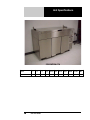
1
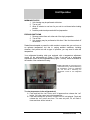
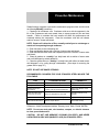
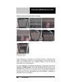
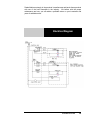
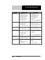
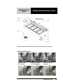
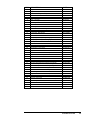
OPERATORS MANUAL
This manual provides
Installation & Operating instructions for
CHICK-FIL-A
REFRIGERATED
BREADING TABLE
For Models:
52365WPRM-CFA
NOTIFY CARRIER OF DAMAGE AT ONCE.
It is the responsibility of the consignee to inspect the
container upon receipt of same and to determine
the possibility of any damage, including concealed
damage. Randell suggests that if you are suspicious
of damage to make a notation on the delivery receipt. It will be the responsibility of the consignee to
file a claim with the carrier. We recommend that you
do so at once.
Manufacture Service/Questions 888-994-7636.
Information contained in this document is known to be
current and accurate at the time of printing/creation.
Unified Brands recommends referencing our product line
websites, unifiedbrands.net, for the most updated product
information and specifications.
P/N OMANUAL_MNL0502-05/05
1055 Mendell Davis Drive
Jackson, MS 39272
888-994-7636, fax 888-864-7636
randell.com
Table of Contents
page 2………………………………….…………Congratulations
page 3……………………………………Parts & Service Hotline
page 3………………………………...…Serial Number Location
page 4-7……………………………….Randell Limited Warranty
page 8…………………………………………Unit Specifications
page 9-10…..……………………………………...Unit Operation
page 11-13……………………………..Preventive Maintenance
page 13………………………………………..Electrical Diagram
page 14……………………………………..……Troubleshooting
page 15-17…………………………….……..Replacement Parts
Congratulations on your recent purchase of Randell food service equipment,
and welcome to the growing family of satisfied Randell customers.
Our reputation for superior products is the result of consistent quality
craftsmanship. From the earliest stages of product design to successive steps
in fabrication and assembly, rigid standards of excellence are maintained by
out staff of designers, engineers, and skilled employees.
Only the finest heavy-duty materials and parts are used in the production of
Randell brand equipment. This means that each unit, given proper
maintenance will provide years of trouble free service to its owner.
difoodservice.com
3
In addition, all Randell food service equipment is backed by
some of the best warranties in the food service industry and by
our professional staff of service technicians.
Retain this manual for future reference.
NOTICE: Due to a continuous program of product improvement, Randell
Manufacturing reserves the right to make changes in design and specifications
without prior notice.
NOTICE: Please read the entire manual carefully before installation. If certain
recommended procedures are not followed, warranty claims will be denied.
MODEL NUMBER _________________________
SERIAL NUMBER _________________________
INSTALLATION DATE _____________________
The serial number is located in the
mechanical housing.
800-621-8560
Randell Manufacturing Service
and Parts Hotline
difoodservice.com
3
Warranty Policies
Congratulations on your purchase of a Randell Manufactured piece of equipment.
Randell believes strongly in the products it builds and backs them with the best
warranty in the industry. Standard with every unit comes the peace of mind that
this unit has been thoroughly engineered, properly tested and manufactured to
excruciating tolerances, by a manufacturer with over 25 years of industry presence.
On top of that front end commitment, Randell has a dedicated staff of certified
technicians that monitor our own technical service hotline at 1-800-621-8560 to
assist you with any questions or concerns that may arise after delivery of your new
Randell equipment.
PARTS WARRANTY
1. One year parts replacement of any and all parts that are found defective in
material or workmanship. Randell warrants all component parts of
manufactured new equipment to be free of defects in material or workmanship,
and that the equipment meets or exceeds reasonable industry standards of
performance for a period of one year from the date of shipment from any
Randell factory, assembly plant or warehouse facility.
NOTE: warranties are effective from date of shipment, with a thirty day
window to allow for shipment, installation and set-up. In the event
equipment was shipped to a site other than the final installation site,
Randell will warranty for a period of three months following installation,
with proof of starting date, up to a maximum of eighteen months from the
date of purchase.
2. Free ground freight of customer specified location for all in warranty parts
within continental U.S. Component part warranty does not cover glass
breakage or gasket replacement. Randell covers all shipping cost related to
component part warranty sent at regular ground rates (UPS, USPS). Freight
or postage incurred for any express or specialty methods of shipping are
the responsibility of the customer.
LABOR COVERAGE
In the unlikely event a Randell manufactured unit fails due to defects in
materials or workmanship within the first ninety days, Randell agrees to pay
reasonable labor incurred. During the first ninety days, work authorizations are
not required for in warranty repairs. However, repair times are limited to
certain flex rate schedules and hours will be deducted from service invoices if
they exceed allowed times without prior approval and a work authorization
number. Warranties are effective from date of shipment, with a thirty day
window to allow for shipment, installation and setup. Where equipment is
shipped to any site other than final installation, Randell will honor the labor
4
800-621-8560
warranty for a period of ninety days following installation with proof of starting
date, up to a maximum of nine months from date of purchase. Travel time is
limited to one hour each direction or two hours per invoice. Any travel time
exceeding two hours will be the responsibility of the customer.
Temperature adjustments are not covered under warranty, due to the wide
range of ambient conditions.
To request a warranty approval number, call our Field Service Department at:
1-800-621-8560
WHEN OPTIONAL 5 YEAR COMPRESSOR WARRANTY APPLIES
1. Provide reimbursement to servicing company for the cost of locally
obtained replacement compressor in exchange for the return of the
defective compressor sent back freight prepaid. Note: Randell
Manufacturing does limit amount of reimbursement allowed and does
require bill from local supply house where compressor was obtained
(customer should not pay servicing agent up front for compressor).
2. Provide repair at the manufacturing facility by requiring that the
defective unit be sent back to Randell freight prepaid. Perform repair at
the expense of Randell and ship the item back to the customer freight
collect.
3. Furnish complete condensing unit freight collect in exchange for the
return of the defective compressor sent back freight prepaid.
(Decisions on whether or not to send complete condensing units will be
made by Randell’s in-house service technician).
WHEN OPTIONAL LABOR EXTENSION POLICY APPLIES
Randell Manufacturing will provide reimbursement of labor invoiced to any
customer that has an optional labor extension of our standard warranty.
(Reasonable geographic and industry rates do apply) Randell offers both 1
and 2 year extensions. Labor extensions begin at the end of our standard
warranty and extend out 9 months to 1 calendar year or 21 months to 2
calendar years from date of purchase.
Please contact Randell
Manufacturing’s technical service hotline at 1-800-621-8560 for details and
warranty authorization numbers.
WHEN EXPORT WARRANTIES APPLY
1. Randell Manufacturing covers all non-electrical components under the
same guidelines as our standard domestic policy.
2. All electrical components operated on 60 cycle power are covered
under our standard domestic policy.
3. All electrical components operated on 50 cycle power are covered for
90 days from shipment only.
4. Extended warranty options are not available from the factory.
ITEMS NOT COVERED UNDER WARRANTY
1. Maintenance type of repairs such as condenser cleaning, temperature
adjustments, clogged drains and unit leveling.
2. Randell does not cover gaskets under warranty. Gaskets are a
maintenance type component that are subject to daily wear and tear
and are the responsibility of the owner of the equipment. Because of
difoodservice.com
5
the unlimited number of customer related circumstances that can cause
gasket failure all gasket replacement issues are considered nonwarranty. Randell recommends thorough cleaning of gaskets on a
weekly basis with a mild dish soap and warm water. With proper care
Randell gaskets can last up to two years, at which time we recommend
replacement of all gaskets on the equipment for the best possible
performance.
NOTICE: FOOD LOSS IS NOT COVERED UNDER WARRANTY
3. Repairs caused by abuse such as broken glass, freight damage, or
scratches and dents.
4. Electrical component failure due to water damage from cleaning
procedures.
QUOTATIONS
Verbal quotations are provided for customer convenience only and are
considered invalid in the absence of a written quotation. Written quotations
from Randell are valid for 30 days from quote date unless otherwise specified.
Randell assumes no liability for dealer quotations to end-users.
SPECIFICATION & PRODUCT DESIGN
Due to continued product improvement, specification and product design may
change without notice. Such revisions do not entitle the buyer to additions.
Changes or replacements for previously purchased equipment.
SANITATION REQUIREMENTS
Certain areas require specific annotation requirements other than N.S.F. &
U.L. standards. Randell must be advised of these specifications before
fabrication of equipment. In these special circumstances, a revised quotation
may be required to cover additional costs. Failure to notify Randell before
fabrication holds the dealer accountable for all additional charges.
CANCELLATIONS
Orders canceled prior to production scheduling entered into
engineering/production and cancelled are subject to a cancellation charge
(contact factory for details).
STORAGE CHARGES
Randell makes every effort to consistently meet our customer’s shipment
expectations. If after the equipment has been fabricated, the customer
requests delay in shipment, and warehousing is required:
1. Equipment held for shipment at purchasers request for a period of 30
days beyond original delivery date specified will be invoiced and
become immediately payable.
2. Equipment held beyond 30 days after the original delivery date
specified will also include storage charges.
SHIPPING & DELIVERY
Randell will attempt to comply with any shipping, routing or carrier request
designated by dealer, but reserves the right to ship merchandise via any
responsible carrier at the time equipment is ready for shipment. Randell will
6
800-621-8560
not be held responsible for any carrier rate differences; rate differences are
entirely between the carrier and purchaser. Point of shipping shall be
determined by Randell (Weidman, MI/Tucson, AZ). At dealer’s request,
Randell will endeavor whenever practical to meet dealer’s request. Freight
charges to be collect unless otherwise noted.
DAMAGES
All crating conforms to general motor carrier specifications. To avoid
concealed damage, we recommend inspection of every carton upon receipt.
In the event the item shows rough handling or visible damage to minimize
liability, a full inspection is necessary upon arrival. Appearance of damage will
require removing the crate in the presence of the driver. A notation must be
placed on the freight bill and signed for by the truck driver at the time of
delivery.
Any and all freight damage that occurs to a Randell piece of
equipment as a result of carrier handling is not considered under warranty, and
is not covered under warranty guidelines. Any freight damage incurred during
shipping needs to have a freight claim filed by the receiver with the shipping
carrier. Consignee is responsible for filing of freight claims when a clear
delivery receipt is signed. Claims for damages must be filed immediately
(within 10 days) by the consignee with the freight carrier and all cartons and
merchandise must be retained for inspection.
RETURNED GOODS
Authorization for return must first be obtained from Randell before returning
any merchandise. Any returned goods shipment lacking the return
authorization number will be refused, all additional freight costs to be borne by
the returning party. Returned equipment must be shipped in original carton,
freight prepaid and received in good conditions. Any returned merchandise is
subject to a minimum handling charge (consult factory for rate).
INSTALLATION
Equipment installation is the responsibility of the dealer and/or their customer.
Randell requires all equipment to be professionally installed.
PENALTY CLAUSES
Dealer penalty clauses, on their purchase order or contractually agreed to
between the dealer and their clients are not binding on Randell. Randell does
not accept orders subject to penalty clauses. This agreement supersedes any
such clauses in dealer purchase orders.
EXPORT POLICY
All quotations for export sales will be handled by Dorian Drake International
(www.doriandrake.com), Randell’s export management organization.
*FOOTNOTES IN REFERENCE TO PARAGRAPHS ABOVE
1. Herein called Randell.
2. NET means list price less discount, warranty, labor policy, freight, Randell delivery and other
miscellaneous charges.
CASH DISCOUNTS WILL BE CALCULATED ON NET ONLY.
difoodservice.com
7
Unit Specifications
52365WPRM-CFA
Model
52365WPRM-CFA
8
L
D
H
Work
Hgt.
Doors
H.P.
Volts
Amps
NEMA
Cubic
Volume
Ship
Wt.
65"
33"
41.25"
38.5"
3
1/3
115
10
5-15P
52.135
492
800-621-8560
Unit Operation
MORNING STARTUP
1. Unit cleaning may be performed at this time.
2. Turn on unit.
3. Allow 45 minutes to one hour for your unit to cool down before loading
product.
4. Load the product and proceed with food preparation.
EVENING SHUT DOWN
1. Remove product from unit at the end of the day’s preparation.
2. Turn off unit.
3. Unit cleaning may be performed at this time if the frost has melted off
the surface.
Randell has attempted to preset the cold controls to ensure that your unit runs at
an optimum temperature, but due to varying ambient conditions, including
elevation, food product as well as type of operation, you may need to alter this
temperature.
Your refrigerated breading table was equipped with a temperature adjustment
control for the refrigerated rail (Figure 1, item A) as well as a temperature
adjustment control for the refrigerated base (Figure 1, item B), which are located on
the outside of the mechanical housing.
Figure 1 illustrates the outer panel of the
mechanical housing. Item A is referencing
the temperature control for refrigerated
rail, and Item B is referencing the
temperature control for the refrigerated
base.
To raise temperature in the refrigerated rail:
A. Push and hold the “set” button until 34 appears then release the “set”
button. 34 is the current set point temperature.
B. Push and release the up arrow 2 times until 36 is displayed. Push and
release the “set” button one time. The new set point, 36, will flash 3
times and then will be locked in.
difoodservice.com
9
To lower temperature in the refrigerated rail:
A. Push and hold the “set” button until 34 appears and then release the
“set” button. 34 is the current set point temperature.
B. Push and release the up arrow 2 times until 32 is displayed. Push and
release the “set” button one time. The new set point, 32, will flash 3
times and then will be locked in.
NOTE: It is recommended to only make changes of 2 degree increments
at a time. Allow for the unit to operate 24 hours between adjustments. If
the 2 degree adjustment is not enough another adjustment can be made.
The maximum highest setting is 38 degrees and the minimum lowest
setting is 28 degrees. If the settings need to go above or below this point
there may be other contributing factors as to the cause of the
temperature variances, please contact the factory at 1-800-621-8560.
The base temperature can also be adjusted by the temperature control dial located
on the front of the refrigeration coil inside the refrigerated base. The thermometer
for the base temperature is located in the mechanical housing (Figure 1, item b).
To raise the temperature in the refrigerated base:
A. Push and hold the “set” button until 34 appears then release the “set”
button. 34 is the current set point temperature.
B. Push and release the up arrow 2 times until 36 is displayed. Push and
release the “set” button one time. The new set point, 36, will flash 3
times and then will be locked in.
To lower temperature in the refrigerated base:
A. Push and hold the “set” button until 34 appears and then release the
“set” button. 34 is the current set point temperature.
B. Push and release the up arrow 2 times until 32 is displayed. Push and
release the “set” button one time. The new set point, 32, will flash 3
times and then will be locked in.
NOTE: It is recommended to only make changes of 2 degree increments at a
time. Allow for the unit to operate 24 hours between adjustments. If the 2
degree adjustment is not enough another adjustment can be made. The
maximum highest setting is 38 degrees and the minimum lowest setting is
28 degrees. If the settings need to go above or below this point there may be
other contributing factors as to the cause of the temperature variances,
please contact the factory at 1-800-621-8560.
10
800-621-8560
Preventive Maintenance
Randell strongly suggests a preventive maintenance program which would include
the following Monthly procedures:
1. Cleaning of all condenser coils. Condenser coils are a critical component in the
life of the compressor and must remain clean to assure proper air flow and heat
transfer. Failure to maintain this heat transfer will affect unit performance and
eventually destroy the compressor. Clean the condenser coils with coil cleaner
and/or a vacuum, cleaner and brush.
NOTE: Brush coil in direction of fins, normally vertically as to not damage or
restrict air from passing through condenser.
2. Clean fan blade on the condensing unit.
3. Clean and disinfect drains with a solution of warm water and bleach.
4. Clean and disinfect drain lines and evaporator pan with a solution of warm water
and bleach.
5. Clean all gaskets on a weekly if not daily basis with a solution of warm water
and a mild detergent to extend gasket life.
6. Clean the grease filter on a weekly if not daily basis with either hot water and a
mild detergent, or by cycling through a dishwasher. (See steps for removing the
grease filter on page 12.)
NOTE: DO NOT USE SHARP UTENSILS.
RECOMMENDED CLEANERS FOR YOUR STAINLESS STEEL INCLUDE THE
FOLLOWING:
JOB
CLEANING AGENT
COMMENTS
Routine cleaning
Soap, ammonia, detergent Medallion
Apply with a sponge or cloth
Fingerprints and smears
Arcal 20, Lac-O-Nu, Ecoshine
Provides a barrier film
Stubborn stains and
discoloration
Cameo, Talc, Zud, First Impression
Rub in the direction of the
polish lines
Greasy and fatty acids,
blood, burnt-on foods
Easy-Off, Degrease It, Oven Aid
Excellent removal on all
finishes
Grease and Oil
Any good commercial detergent
Apply with a sponge or cloth
Restoration/Preservation
Benefit, Super Sheen
Good idea monthly
Reference: Nickel Development Institute, Diversey Lever, Savin, Ecolab, NAFEM.
NOTE: Do not use steel pads, wire brushes, scrapers, or chloride cleaners
to clean your stainless steel.
CAUTION: DO NOT USE ABRASIVE CLEANING SOLVENTS, AND NEVER
USE HYDROCHLORIC ACID (MURIATIC ACID) ON STAINLESS STEEL.
difoodservice.com
11
Preventive Maintenance (cont.)
Steps for removing the grease filter for cleaning.
Step 1: Locate grease filter
on the front of the condenser
air in duct.
Step 2: Locate finger hole
opening to remove filter without
the use of tools.
Step 3: Insert finger and force
filter upwards.
Step 4: Filter should fall
out in your hands.
Step 5: Pull downwards to
release the filter at the top.
Step 6: Filter should fall
out of the top holding bracket.
Step 7: Removing the filter also
also allows access to the
condenser for cleaning.
Proper maintenance of equipment is the ultimate necessity in preventing costly
repairs. By evaluating each unit on a regular schedule, you can often catch and
repair minor problems before they completely disable the unit and become
burdensome on your entire operation.
For more information on preventive maintenance, consult your local service
company or CFESA member. Most repair companies offer this service at very
reasonable rates to allow you the time you need to run your business along with
the peace of mind that all your equipment will last throughout its expected life.
These services often offer guarantees as well as the flexibility in scheduling or
maintenance for your convenience.
12
800-621-8560
Randell believes strongly in the products it manufactures and backs those products
with one of the best warranties in the industry. We believe with the proper
maintenance and use, you will realize a profitable return on your investment and
years of satisfied service.
Electrical Diagram
difoodservice.com
13
Trouble Shooting Guide
SYMPTOM
POSSIBLE CAUSE
PROCEDURE
Unit doesn't run
1.
2.
3.
4.
5.
6.
7.
8.
No power to unit
Temperature control turned off
Temperature control faulty
Compressor overheated
Condenser fan faulty
Overload protector faulty
Compressor relay faulty
Compressor faulty
1.
2.
3.
4.
5.
6.
7.
8.
Plug in unit
Check temperature control
Test temperature control
Clean condenser coil
Service condenser fan
Test overload
Test relay
Call for service at 800-621-8561
Unit short cycles
1.
2.
3.
4.
Condenser coil dirty
Condenser fan faulty
Compressor faulty
Overload repeatedly tripping
1.
2.
3.
4.
Clean coil
Service fan and motor.
Call for service at 800-621-8561
Check outlet voltage
Unit runs constantly
1. Condenser coil dirty
2. Condenser fan faulty
Unit not cold enough
Unit too cold
Unit noisy
14
1. Temperature control set too
high
2. Temperature control faulty
3. Condenser coil dirty
4. Refrigerant leaking or
contaminated
1. Clean coil
2. Service condenser motor
1. Adjust control to lower setting
2. Test control
3. Clean coil
4. Call for service at 800-621-8561
1. Temperature control set too low
2. Temperature control faulty
1. Adjust control to raise setting
2. Test control
1. Compressor mountings loose or
hardened.
1. Tighten or replace compressor
mountings
2. Condenser fan damaged or
hitting fan shroud
2. Inspect condenser fan
800-621-8560
Replacement
Parts
Refrigerated Breading Tables
CAUTION: Hold lid with both hands securely at all times during opening and closing.
Safety Latch Operation
Safety Latch Open
(Not Engaged)
Safety Latch Partially
Closed (Not Engaged)
Safety Latch Closed
(Engaged)
difoodservice.com
15
Accessing the Mechanical Housing
Step 1: Remove 4 screws.
16
800-621-8560
Step 2: Pull off side panel.
Step 3: Access components.
ITEM
DESCRIPTION
PART #
1
Hinged Cover with Recessed Handle
RP PCR0501
2
Hinge Assembly with Safety Latch
RP HNG0501
3
Gas Assist for Hinge Assembly
RP SPT0502
4
Drain Screen, 2”
RP DSN002
5
Elbow, 1 1/2" PVC Fem x Glue
PB ELB9905
6
Pipe, 1 1/2" PVC
PB PIP150
7
Ball Valve, 1 _" PVC Female
PB VLV9901
8
Dixell Digital Control for Base
RP CNT0204
9
Rocker On/Off Switch for Rail
EL SWT140
10
Dixell Digital Control for Rail
RP CNT0501
11
Clean Condenser Indicator Light
EL LGT0305
12
Louver Knob, Aluminum
HD PIN0102
13
Louver Door, Right Hinged
RP LVR0504
14
Shelf Pins, Aluminum
HD PIN0102
15
Shelf, 13-1/8” x 25-1/4" Stainless Steel
HD SHL015SS
16
Strap Hinge Assembly for Right Hinging
RP HNG9901
Strap Hinge Assembly for Left Hinging
RP HNG9902
17
Toe Style Bracket/Door Handle, Stainless Steel
RP HDL0501
18
Door Gasket
IN GSK1020
19
Evaporator Fan Motor, 120V w/blade
EL MTR2338
20
Temperature Control Probe
RF CNT0301-1
21
Evaporator Condensate Pan, Plastic
RP DRP107
22
Expansion Valve
RF VLV404
23
Shield Panel for Base Coil Assembly
RP PNL107
24
Evaporator Coil Assembly
RP CSY108SL
24A
Evaporator Coil
RF COI107
25
Solenoid Valve
RF SOL9801
26
Evaporator Fan Shroud
RP SHD107
27
Mounting Support Bracket for Base Coil Assembly
RP SPT0500
28
Door Assembly with Toe Bracket, Left Hinge
RP DOR0503
29
Door Assembly with Toe Bracket, Right Hinge
RP DOR0504
30
Caster, 4-1/2” Overall with locking mechanism
HD CST030
Caster, 4-1/2” Overall without locking mechanism
HD CST031
31
Condensing Unit Shroud
RP HSG0501
32
Magnetic Catch & Bracket Assembly for Louver Door
RP CTH0501
33
Snap Button, Louver Hinge
HD BTN9901
34
Magnetic Catch Plate
RP BRK0508
35
Grease Filter, Condenser 9-1/2” x 11” Alum. w/pull handle
HD FLT0202
36
Condensing Unit
RF CON9901
37
Condenser Fan Blade
RF FAN007
38
Condenser Fan Motor
EL MTR300
39
Compressor
RF CMP9902P
16A
30A
difoodservice.com
17