1
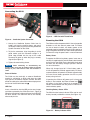
Operator’s Manual
TM
WARNING!
Read this Operator’s Manual
carefully before using this
tool. Failure to understand
and follow the contents of
this manual may result in
electrical shock, fire and/or
serious personal injury.
TM
Record product serial number below as it appears on the nameplate.
Serial
No.
TM
Table of Contents
Recording Form for Machine Serial Number ������������������������������������������������������������������������������������������������������������� 1
Safety Symbols�������������������������������������������������������������������������������������������������������������������������������������������������������������� 1
General Safety Rules
Work Area Safety���������������������������������������������������������������������������������������������������������������������������������������������������������1
Electrical Safety ����������������������������������������������������������������������������������������������������������������������������������������������������������1
Personal Safety�����������������������������������������������������������������������������������������������������������������������������������������������������������1
Equipment Use and Care��������������������������������������������������������������������������������������������������������������������������������������������1
Battery Use and Care������������������������������������������������������������������������������������������������������������������������������������������������� 2
Service����������������������������������������������������������������������������������������������������������������������������������������������������������������������� 2
Specific Safety Information������������������������������������������������������������������������������������������������������������������������������������������ 2
CS10 Safety ��������������������������������������������������������������������������������������������������������������������������������������������������������������� 2
Description, Specifications, and Standard Equipment
Description����������������������������������������������������������������������������������������������������������������������������������������������������������������� 3
Specifications������������������������������������������������������������������������������������������������������������������������������������������������������������� 4
Standard Equipment��������������������������������������������������������������������������������������������������������������������������������������������������� 4
CS10 Components��������������������������������������������������������������������������������������������������������������������������������������������������������� 4
Keypad and Icon Legends�������������������������������������������������������������������������������������������������������������������������������������������� 5
Pre-Operation Inspection���������������������������������������������������������������������������������������������������������������������������������������������� 6
Work Area and Equipment Set Up
CS10 Placement��������������������������������������������������������������������������������������������������������������������������������������������������������� 7
Connecting the CS10���������������������������������������������������������������������������������������������������������������������������������������������������� 8
Powering the CS10����������������������������������������������������������������������������������������������������������������������������������������������������� 8
Interface Overview������������������������������������������������������������������������������������������������������������������������������������������������������ 9
Operating Instructions
Starting Up the CS10������������������������������������������������������������������������������������������������������������������������������������������������ 10
Jobs��������������������������������������������������������������������������������������������������������������������������������������������������������������������������� 11
Recording Autolog Video������������������������������������������������������������������������������������������������������������������������������������������� 11
Recording Video�������������������������������������������������������������������������������������������������������������������������������������������������������� 11
Taking Photos������������������������������������������������������������������������������������������������������������������������������������������������������������ 11
Adjusting Settings����������������������������������������������������������������������������������������������������������������������������������������������������� 13
Delivering Reports by USB Thumb Drive����������������������������������������������������������������������������������������������������������������� 14
SeeSnake HQ Software ������������������������������������������������������������������������������������������������������������������������������������������ 14
Maintenance Instructions
Software Updates����������������������������������������������������������������������������������������������������������������������������������������������������� 15
Cleaning������������������������������������������������������������������������������������������������������������������������������������������������������������������� 15
Accessories������������������������������������������������������������������������������������������������������������������������������������������������������������������ 16
Transport and Storage������������������������������������������������������������������������������������������������������������������������������������������������ 16
Service and Repair������������������������������������������������������������������������������������������������������������������������������������������������������ 16
Disposal������������������������������������������������������������������������������������������������������������������������������������������������������������������������17
Battery Disposal�����������������������������������������������������������������������������������������������������������������������������������������������������������17
Troubleshooting����������������������������������������������������������������������������������������������������������������������������������������������������������� 18
Lifetime Warranty �����������������������������������������������������������������������������������������������������������������������������������������Back Cover
Other trademarks or trade names may be used in this document to refer to either the entities claiming the marks and names or their products. RIDGID
disclaims any proprietary interest in trademarks and trade names other than its own.
ii - English
TM
Safety Symbols
In this operator’s manual and on the product, safety symbols and signal words are used to communicate important safety
information. This section is provided to improve understanding of these signal words and symbols.
This is the safety alert symbol. It is used to alert you to potential personal injury hazards. Obey all safety messages that follow
this symbol to avoid possible injury or death.
DANGER
DANGER indicates a hazardous situation which, if not avoided, will result in death or serious injury.
WARNING
WARNING indicates a hazardous situation which, if not avoided, could result in death or serious injury.
CAUTION
CAUTION indicates a hazardous situation which, if not avoided, could result in minor or moderate injury.
NOTICE
NOTICE indicates information that relates to the protection of property.
This symbol means read the operator’s manual carefully before using the equipment. The operator’s manual contains
important information on the safe and proper operation of the equipment.
This symbol means always wear safety glasses with side shields or goggles when handling or using this equipment to reduce
the risk of eye injury.
This symbol indicates the risk of electrical shock.
General Safety Rules
• If operating equipment in a damp location is
WARNING
Read all safety warnings and instructions. Failure to
follow the warnings and instructions may result in
electric shock, fire, and/or serious injury.
• Keep all electrical connections dry and off the
SAVE THESE INSTRUCTIONS!
Work Area Safety
• Keep your work area clean and well lit. Cluttered
or dark areas invite accidents.
unavoidable, use a ground fault circuit interrupter
protected supply to reduce the risk of electric
shock.
ground. Do not touch equipment or plugs with wet
hands to reduce the risk of electrical shock.
Personal Safety
• Stay alert, watch what you are doing, and use
atmospheres, such as in the presence of
flammable liquids, gases, or dust. Equipment can
create sparks which may ignite the dust or fumes.
common sense when operating equipment. Do
not use equipment while you are tired or under the
influence of drugs, alcohol, or medication. A moment
of inattention while operating equipment may result
in serious personal injury.
• Keep children and bystanders away while
• Use personal protective equipment. Always wear
• Do not operate equipment in explosive
operating equipment. Distractions can cause you
to lose control.
Electrical Safety
• Avoid body contact with earthed or grounded
surfaces such as pipes, radiators, ranges, and
refrigerators. There is an increased risk of electrical
shock if your body is earthed or grounded.
• Do not expose equipment to rain or wet
conditions. Water entering equipment will increase
the risk of electrical shock.
• Do not abuse the cord. Never use the cord for
carrying, pulling, or unplugging the power tool. Keep
cord away from heat, oil, sharp edges, and moving
parts. Damaged or entangled cords increase the risk
of electric shock.
eye protection. The appropriate use of protective
equipment such as a dust mask, non-skid safety
shoes, a hard hat, and hearing protection will reduce
personal injuries.
• Do not overreach. Keep proper footing and balance
at all times. This enables better control of the
equipment in unexpected situations.
• Dress properly. Do not wear loose clothing or
jewelry. Keep your hair, clothing, and gloves away
from moving parts. Loose clothes, jewelry, and long
hair can be caught in moving parts.
Equipment Use and Care
• Do not force equipment. Use the correct equipment
for your application. The correct equipment will do
the job better and safer at the rate for which it is
designed.
English - 1
TM
• Do not use equipment if the power switch does
not turn it ON and OFF. Any equipment that cannot
be controlled with the power switch is dangerous and
must be repaired.
• Disconnect the plug from the power source and/
or the battery pack from the equipment before
making adjustments, changing accessories, or
storing. Preventive safety measures reduce the risk
of injury.
• Store idle equipment out of the reach of children
and do not allow persons unfamiliar with the
equipment or these instructions to operate the
equipment. Equipment can be dangerous in the
hands of untrained users.
• Maintain equipment. Check for misalignment or
binding of moving parts, missing parts, breakage
of parts, and any other condition that may affect
the equipment’s operation. If damaged, have the
equipment repaired before use. Many accidents are
caused by poorly maintained equipment.
• Use
the equipment and accessories in
accordance with these instructions; taking into
account the working conditions and the work to
be performed. Use of the equipment for operations
different from those intended could result in a
hazardous situation.
• Use only accessories that are recommended by
the manufacturer for your equipment. Accessories
that may be suitable for one piece of equipment may
become hazardous when used with other equipment.
• Keep handles dry, clean, and free from oil and
grease. This allows for better control of the equipment.
Battery Use and Care
• Recharge only with the charger specified by the
manufacturer. A charger suitable for one type of
battery pack may create a risk of fire when used with
another battery pack.
• Use equipment only with specifically designated
battery packs. Use of any other battery packs may
create a risk of injury and fire.
• Do not probe battery with conductive objects.
Shorting of battery terminals may cause sparks,
burns, or electrical shock. When the battery pack is
not in use, keep it away from other metal objects, like
paper clips, coins, keys, nails, screws or other small
metal objects that can make a connection from one
terminal to another. Shorting the battery terminals
together may cause burns or a fire.
• Under abusive conditions, liquid may eject from
battery; avoid contact. If contact occurs, flush with
2 - English
water. If liquid contacts eyes, seek medical help.
Liquid ejected from the battery may cause irritation
or burns.
• Use and store batteries and chargers in
dry, appropriate temperature areas. Extreme
temperatures and moisture can damage batteries
and result in leakage, electrical shock, fire or burns.
See charger manual for more information.
• Do not cover charger while in use. Proper
ventilation is required for correct operation. Covering
charger in use could result in fire.
• Properly dispose of batteries. Exposure to high
temperatures can cause the batteries to explode;
do not dispose of in a fire. Some countries have
regulations concerning battery disposal. Follow all
applicable regulations.
Service
Ensure a qualified repair person services your equipment
using only identical replacement parts to maintain
the safety of the tool. Remove the batteries and refer
servicing to qualified service personnel under any of the
following conditions:
• If liquid has been spilled or objects have fallen into
product.
• If the product does not operate normally when
following the operating instructions.
• If the product has been dropped or damaged.
• When the product exhibits a distinct change in
performance.
Specific Safety Information
WARNING
This section contains important safety information
that is specific to the CS10. Read these precautions
carefully before using the CS10 to reduce the risk of
electrical shock, fire, or other serious personal injury.
SAVE ALL WARNINGS AND INSTRUCTIONS
FOR FUTURE REFERENCE!
Keep this manual with the equipment for use by the operator.
CS10 Safety
• An improperly grounded electrical outlet can
cause electrical shock and/or severely damage
equipment. Always check the work area for a
properly grounded electrical outlet. The presence of
a three-prong or GFCI outlet does not ensure that
the outlet is properly grounded. If in doubt, ensure a
licensed electrician inspects the outlet.
TM
• Only power the CS10 with the specified battery or
a double insulated power supply.
• Do not operate this equipment if operator or
machine is standing in water. Operating machine
while in water increases the risk of electrical shock.
• The CS10 is not waterproof. Only the camera and
push cable are waterproof. To decrease the risk or
electrical shock, do not expose the equipment to
water or rain.
• Do not use where a danger of high voltage
contact is present. The equipment is not designed
to provide high voltage protection and isolation.
• Read and understand this operator’s manual,
the SeeSnake Pipe Inspection Reel operator’s
manual, the instructions for any other equipment
in use, and all warnings before operating the
CS10. Failure to follow instructions may result in
property damage and/or serious personal injury.
• Always use appropriate personal protective
equipment while handling and using equipment
in drains. Drains may contain chemicals, bacteria,
and other substances that may be toxic or infectious,
or that may cause burns or other issues. Appropriate
personal protective equipment always includes
safety glasses, but may also include drain cleaning
gloves or mitts, latex or rubber gloves, face shields,
goggles, protective clothing, respirators, and steel
toed shoes.
• If using drain cleaning equipment at the same
time as using drain inspection equipment, wear
RIDGID Drain Cleaning Gloves. Never grasp the
rotating drain cleaning cable with anything other
than RIDGID Drain Cleaning Gloves, including a rag
which can wrap around the cable and cause hand
injuries. Only wear latex or rubber gloves under
RIDGID Drain Cleaner Gloves. Do not use damaged
drain cleaning gloves.
• Practice good hygiene. Use hot, soapy water to
• To prevent damage to the product and to decrease
the risk of injury, do not expose equipment to
mechanical shocks.
The warnings, cautions, and instructions discussed
in this operator’s manual cannot cover all possible
conditions and situations that may occur. It must be
understood by the operator that common sense and
caution are factors which cannot be built into this
product, but must be supplied by the operator.
The EC Declaration of Conformity (890-011-320.10) will
accompany this manual as a separate booklet when
required. If you have any question concerning this
RIDGID product:
• Contact your local RIDGID distributor.
• Visit www.RIDGID.com or www.RIDGID.eu to find
your local RIDGID contact point.
• Contact RIDGID Technical Services Department
at [email protected], or in the U.S.
and Canada call 800-519-3456.
Description, Specifications, and
Standard Equipment
Description
The SeeSnake CS10 is a portable monitor and camera
control unit designed to easily connect to any SeeSnake
Reel and camera. The CS10 can capture audio, video,
and still images and assemble them automatically into
an HTML report on a USB thumb drive . The CS10
contains readily accessible controls to adjust the
camera and the display, and to control the in‑line Sonde
built into many SeeSnake cameras.
The built‑in Sonde enables the operator to locate the
camera underground. The CS10 can also be connected
to an external Line Transmitter which can line trace the
path of a SeeSnake cable in a pipe.
wash hands and other body parts exposed to drain
contents after handling or using drain inspection
equipment. To prevent contamination from toxic
or infectious material, do not eat or smoke while
operating or handling drain inspection equipment.
The CS10 is also fully compatible with SeeSnake HQ
software that can quickly generate customized reports
containing videos and photos captured during an
inspection that can be emailed, printed, burned onto
DVD, or exported for viewing in a web browser.
• The equipment is intended for indoor use when
Download the latest version of SeeSnake HQ for free
from www.hq.seesnake.com.
powered by the AC power supply. When powered
by battery, protect the product from exposure to
weather. Since this product is not waterproof, do
not expose the equipment to moisture or rain. Water
entering the unit housing can increase the risk of
safety hazards and electrical shock. Only the camera
and cable in a SeeSnake Pipe Inspection Reel are
waterproof.
English - 3
TM
CS10 Components
Specifications
Table 1
SeeSnake® CS10 Specifications
Weight:
with two batteries
14.8 lb [6.7 kg]
without batteries
12.0 lb [5.4 kg]
Front Cover
Dimensions:
Length
14.3 in [36.3 cm]
Width
11.9 in [30.2 cm]
Height
12.4 in [31.5 cm]
Power rating
100 – 240 VAC/50 – 60Hz,
60 W
Battery type
18 V Li-Ion Rechargeable
LCD Screen
Operating environment:
Temperature
Storage temperature
Humidity
Altitude
CS10 Main Keypad
32°F – 104°F
[0°C – 40°C]
14°F – 158°F
[−10°C – 70°C]
5% – 95% RH
13,120 ft [4,000 m]
LCD screen:
Resolution
Display size (H × V)
Contrast ratio
Brightness
Power consumption
Standard Equipment
• CS10
Mini Keypad
VGA 640 × 480 pixels
12.1 in [30.7 cm]
SeeSnake System Connector
700:1
500 Cd/m2
Figure 1 – Front View (Open)
13 W
Serial Number Label
External Power Cord
• Operator’s Manual
• Instructional DVD
Battery Docks
Figure 2 – Rear View
4 - English
Tilt Stand
TM
LED Brightness Key
Power Key
Sonde Key
Zero Key
Transmitter Clip-on
Terminal
Video Out
Speaker
USB Port Cover
USB Port
Figure 3 – CS10 Mini Keypad
Figure 5 – CS10 Connections
Keypad and Icon Legends
Table 2
CS10 Keypads
Video Key
Photo Key
Battery Indicator LEDs
Menu Key
Main Keypad
Photo Key
Video Key
Autolog Key
Select Key
Arrow Keys
Menu Key
Job Manager Key
Autolog Key
Arrow Keys
Job Manager Key
Microphone Mute Key
Select Key
Figure 4 – CS10 Main Keypad
Microphone Mute Key
Mini Keypad
Power Key
LED Brightness Key
Sonde Key
Zero Key
English - 5
TM
Table 3
Connection Icons
Icon
Definition
Pre-Operation Inspection
WARNING
Video Out
Video Connect
(SeeSnake System Connector)
Transmitter Clip-on Terminal
Icon
Table 4
CS10 Screen Icons
Name / Meaning
Loading Icon
Saved Icon
USB Icon
Corrupt Thumb Drive in USB Port
Icon
Job Saving Icon
Saving to USB Icon
Insert Thumb Drive Icon
Thumb Drive Ejected Icon
Thumb Drive Error
Thumb Drive Full Icon
Autolog Icon
Autolog Saving Icon
Before each use, inspect your CS10 and correct
any problems to reduce the risk of serious injury
from electrical shock or other causes and prevent
machine damage.
1. Confirm that the power is OFF, that any external
power and cords are disconnected, and that the
battery is removed. Inspect the cords, cables, and
connectors for damage or modification.
2. Clean any dirt, oil, or other contamination from the
CS10 to aid in inspection and to prevent the unit
from slipping from your grip during transport or use.
3. Inspect the CS10 for any broken, worn, missing,
misaligned or binding parts, or any other condition
which might prevent safe, normal operation.
4. Inspect any other equipment being used per its
instructions to make sure it is in good, usable
condition.
5. If any problems are found, do not use the unit until
the problems are corrected.
Work Area and Equipment Set Up
WARNING
Autolog Not Saved Icon
Video Icon
Video Saving Icon
Video Not Saved Icon
Photo Icon
Photo Saving Icon
Photo Not Saved Icon
External Power Icon
Set up the CS10 and work area in accordance with
these procedures to reduce the risk of injury from
electrical shock, fire, and other causes and to prevent
damage to the CS10.
1. Check work area for the following:
• Adequate lighting.
• Flammable liquids, vapors, or dust that may ignite.
If present, do not work in area until sources have
been identified and corrected. The CS10 is not
explosion proof. Electrical connections can cause
sparks.
6 - English
TM
• Clear, level, stable dry place for operator. Do not
use the machine while standing in water.
• If using external power, clear path to the electrical
outlet that does not contain any potential sources
of damage for the power cord.
2. Inspect the work and determine the correct RIDGID
equipment for the task. Using incorrect equipment
for an application can cause injury or equipment
damage. For a complete list of RIDGID inspection
equipment, consult the Ridge Tool Catalog at
www.ridgid.com or www.ridgid.eu.
3. Ensure the equipment has been inspected as
specified by the operator’s manual.
4. Evaluate the work area and erect barriers as
necessary to keep bystanders away. Bystanders
can distract the operator during use. If working
near traffic, erect cones or other barriers to alert
drivers.
To set up the tilt stand, perform the following:
1. Use the handle on the top of the CS10 to place the
unit in the desired location (See Item 1, Figure 6).
2. Tilt the unit back slightly and pull forward on the tilt
stand until it locks in place (See Item 2, Figure 6).
To store the tilt stand, tilt the unit back slightly, and push
the tilt stand toward the back of the unit until it lays flat
against the base of the unit.
Front Cover
The CS10 front cover serves two purposes: it protects
the unit during transport and storage, and it acts as a
sun hood to reduce glare during inspections.
Opening the Front Cover
5. Remove fixtures such as the water closet or sink to
allow access as required.
CS10 Placement
Place the CS10 in an area and in a position that allows
easy access and viewing while manipulating the camera
and push cable during an inspection. To reduce the risk
of electrical shock and equipment damage, ensure the
location is dry and that the CS10 and other equipment
will not get wet during use. The CS10 is not waterproof
and exposure to wet conditions can cause electrical
shock or equipment damage.
Place camera and the SeeSnake Reel as instructed in
the operator’s manual. Ensure the CS10 and SeeSnake
Reel are stable.
Tilt Stand
1
Figure 7 – Opening the Front Cover
To open the front cover, perform the following:
1. Depress the orange Front Cover Release Buttons
on each side of the unit (See Figure 7).
2. Raise the front cover to its uppermost position
where it will lock securely into place.
Closing the Front Cover
To close the front cover, perform the following:
Disconnect all connections, including the SeeSnake
System Cable and USB devices. Keeping clear of the
front cover, gently depress the orange buttons to drop
the cover to the lowest position. Press the cover into
place until it locks.
2
Figure 6 – Setting Up the Tilt Stand
English - 7
TM
Connecting the CS10
1
Figure 9 – USB Port with Thumb Drive
Figure 8 – SeeSnake System Connector
1. Unwrap the SeeSnake System Cable from its
holder, pull back the locking sleeve, and match
the System Cable plug to the matching SeeSnake
System Connector on the CS10.
2. To join the connectors, align the guide pin to the
guide socket, push the connector straight in. A
guide ridge molded into the top of the cable
connector will point up when the plug is correctly
aligned (See Figure 8).
3. Tighten the outer locking sleeve.
NOTICE
When connecting or disconnecting the
System Cable, twist only the locking sleeve! To prevent
damage to pins, never bend or twist the connector or
cable!
External Monitor
The CS10 may be used with an external SeeSnake
monitor by connecting an RCA cable from the video
input port on the external monitor. Connect the other
end of the cable to the yellow CS10 video output port on
the front of the CS10 marked with
USB Port
Insert a thumb drive into the USB port to store images
and video captured by the CS10 (See Item 1, Figure 9).
When the thumb drive is being accessed, the USB LED
will blink steadily. The USB LED will be ON steadily
when ready for use.
Powering the CS10
The CS10 can either be powered with Li-Ion rechargeable
batteries or with the external power cord. To reduce
the risk of electrical shock, use battery power as the
preferred powering method and only install batteries or
plug in the power cord with dry hands. Never operate the
unit from AC using the power cord in a wet environment.
Battery Power
To operate the CS10 using battery power, insert one or
two fully charged batteries onto the battery dock located
on the back of the CS10. Ensure the battery locks onto
the dock. See the Battery Charger Operator’s Manual
for more information.
When fully charged, one 18 V Li-Ion battery rated at
2.2 Ah will power the CS10 for approximately 1.75 hours;
and two batteries will power the CS10 for approximately
4.5 hours. Actual battery operation time will vary with
battery rating and use.
If operating the CS10 on AC power and if at least one
battery is also installed, the External Power Icon
will appear in the Status Overlay for 3 seconds if the
CS10 is disconnected from AC power to indicate the
switch to battery power.
Checking Battery Status: LEDs
The CS10 has four battery indicator LEDs, two for each
battery, located just below the screen (See Figure 10).
Figure 10 – Battery Indicator LEDs
8 - English
TM
When the unit is turned ON and batteries are in the
battery docks, the battery indicator LEDs on the CS10
will reflect the state of each battery as shown in Table 5.
Table 5
Battery Status LED Indicators
LED Behavior
Meaning
Left LED is green
Right LED is OFF
Battery full charge
Left LED is green
Right LED is red
Battery partial charge
Left LED is OFF
Right LED is red
Blinking red and
beeps
Interface Overview
Navigating
Use the arrow keys on the CS10 to navigate through
menus and screens. Use the Select Key
to make
selections and to apply changes. Use the Menu Key
to move backwards through menus and screens, and to
cancel out of a menu.
Table 6
CS10 Keys and Functions
Name
Function
Battery low
Power Key
Turns the CS10 ON or OFF
Replace batteries
immediately.
Shutdown in 1 minute
Select Key
Used to select menu items.
Arrow Keys
Used to navigate menus and
screens.
Menu Key
Allows access to the Settings,
Display, Language, and Media
Menus.
Photo Key
Takes a photo.
Autolog Key
Starts and stops Autolog video
recording. Autolog videos
are made up of continuous
audio recording and stillimage frames taken at regular
intervals and saved in a
compressed format. When an
Autolog video is recording, the
LED located on the bottom of
the Autolog Key will be red.
Video Key
Starts and stops video
recording. When a video is
recording, the LED located on
the bottom of the Video Key
will be red.
Job Manager
Key
Opens a menu to allow the
manual ejection of the thumb
drive, the manual creation of a
Report, and access to the list
of files on the thumb drive for
viewing.
Microphone
Mute Key
Toggles the microphone ON
or OFF. When ON, the LED on
the Microphone Mute Key will
be gold.
Solid red and
continuous tone
Dead batteries.
Shutdown in 5 seconds
Slow blink
External power in use.
Beeps when disconnected
Outlet Power
Icon
To operate the CS10 using AC power, locate the power
cord on the back of the unit. Unhook the Velcro® strap
and remove the plug from its holder (See Figure 12).
Plug the power cord into a standard outlet. If using an
extension cord no greater than 25 ft [7.6 m], ensure
the cord has a gauge of at least 18 AWG. If using an
extension cord greater than 25 ft [7.6 m], ensure the
cord has a gauge of at least 16 AWG.
Figure 11 – Power Cord and Power Cord Wrap
NOTE
The provided external power supply is
intended for indoor use only.
English - 9
TM
Table 6
CS10 Keys and Functions
Icon
Name
Function
LED Brightness
Key
Press to step up or down
through various brightness
levels or press once and then
use the arrow keys to step
through the brightness levels.
Sonde Key
Toggles the Sonde ON or OFF.
Zero Key
Press the Zero Key once to
reset a temporary relative
zero point for intermediate
measurement. Relative zero
will appear in brackets. Press
the Zero Key a second time to
stop relative zero and return to
your actual count. You can also
press and hold the Zero Key to
do a hard reset.
LED Brightness Key
The LED Brightness Key
controls the brightness of
the LEDs in the camera. At minimum brightness the
blue LED next to the LED Brightness Key
will be OFF
and at maximum brightness the LED will be ON steadily.
In between, the LED will blink faster the brighter the
setting. In addition to the blinking LED, an indicator bar
will appear in the Status Overlay to visually represent
the increasing and decreasing camera LED brightness.
Microphone Mute Key
percentage of space remaining on the USB thumb drive
plugged into the USB port.
Operating Instructions
WARNING
Always wear eye protection to protect your eyes against
dirt and other foreign objects.
When inspecting drains that might contain hazardous
chemicals or bacteria, wear appropriate protective
equipment, such as latex gloves, goggles, face shields,
and respirators to prevent burns and infections.
Do not operate this equipment if operator or machine
is standing in water. Operating the CS10 while in water
increases the risk of electrical shock. Rubber soled, nonslip shoes can help prevent slipping and electric shock,
especially on wet surfaces.
Follow operating instructions to reduce the risk of injury
from electrical shock and other causes.
Starting Up the CS10
Start the CS10 in accordance with the following:
1. Check that the unit is properly set up.
2. Connect the CS10 to both a power source and a
SeeSnake camera inspection system.
3. Place the camera head into the inspection start
point, typically the pipe entrance.
The Microphone Mute Key
is ON by default, meaning
that the microphone is unmuted and audio is being
recorded. Press the Microphone Mute Key
to mute
the audio when recording video or Autolog video.
4. Press the Power Key
camera ON.
Screen
5. If desired, zero the counter by pressing and holding
the Zero Key .
The on-screen interface has two regions: the Live View
and the Status Overlay.
Live View is the term for the largest area of the screen
where the live video feed appears.
The Status Overlay appears at the bottom of the screen
and displays the time, date, and if equipped with the
SeeSnake Reel, the CountPlus distance count. If the
attached SeeSnake Reel does not have a CountPlus,
four dashes “----” will appear in the Status Overlay to
indicate that the CS10 cannot measure the cable count.
During video or Autolog video recording and after
taking a photo, the Status Overlay will also include the
10 - English
to turn the CS10 and
6. Push the camera head through the line. Proceed
with pipe inspection in accordance with the
SeeSnake Reel’s operator’s manual.
After completing the start up, the display will show a
view from the camera head. While pushing the camera
through a pipe, watch the screen to monitor the camera.
TM
Jobs
Recording Video
The CS10 automatically saves photos, videos, and
Autolog videos to the latest Job on the thumb drive. The
CS10 will open a new Job if there is not already one
on the thumb drive. The CS10 will save media files to a
new session on the thumb drive when the thumb drive
is ejected and when the CS10 shuts down.
Press the Video Key
to start recording a video. The
Video Icon
will appear briefly at the start of a video
recording. The Video LED on the Main Keypad will also
be lit during video recording.
Although the CS10 will turn ON and enable viewing with
the camera, the CS10 cannot capture video, Autolog
video, or photos until a thumb drive is inserted into the
USB port.
If a thumb drive is not in the USB port and if the Photo
Key , Video Key , or Autolog Key
is pressed, the
CS10 will display the Insert Thumb Drive Icon
,
the CS10 will beep, and the USB LED will blink rapidly.
After inserting a thumb drive into the USB port, press
the Photo Key
, Video Key
, or Autolog Key
again to capture media.
Recording Autolog Video
Autolog video captures a highly compressed video of
an inspection, but uses a smaller file size than standard
video. An Autolog video recording saves screen images
in a motion JPEG (MJPEG) video format at the rate of
four frames per second. When the camera does not
move and when the counter does not change, the CS10
will stop adding new frames until the camera moves
again.
Press the Autolog Key
to start recording an Autolog
video. The Autolog Icon
will briefly appear at the start
of each Autolog video recording. The Autolog LED will
also be lit during Autolog recording.
To stop the Autolog recording, press the Autolog Key
again. When the CS10 ends Autolog recording, the
Loading Icon
appears. While saving the Autolog file
to the thumb drive, the Autolog Saving Icon
appears. The Saved Icon
will appear when the CS10
has successfully saved the Autolog file to the thumb
drive.
The CS10 records audio continuously during an Autolog
video recording, regardless of camera movement. Press
the Microphone Mute Key
to turn off the microphone
and to record an Autolog video without audio. When
muted, the LED on the Main Keypad will be OFF.
Press the Photo Key
or the Video Key
to capture
additional photos or higher frame rate video clips while
recording an Autolog video.
To stop video recording, press the Video Key
again.
When the CS10 ends video recording, the Loading
Icon
will appear. While saving the Video file to the
thumb drive, the Video Saving Icon
will appear.
The Saved Icon
will appear when the CS10 has
successfully saved the video file to the thumb drive.
The CS10 records audio continuously during a video
recording, regardless of camera movement. Press the
Microphone Mute Key
to turn OFF the microphone
and to record a video without audio. When muted, the
LED on the Main Keypad will be OFF.
Video and Autolog video can be recorded simultaneously
and independent of each other. Both video recording
types can be started and stopped without affecting the
other.
Taking Photos
Press the Photo Key
to take a photo. The Status
Overlay will appear for 3 seconds after the photo has
been taken. While saving the photo, the CS10 will
display the Photo Saving Icon
. The Saved Icon
will appear to indicate that the photo has been saved
to the thumb drive.
Annotating an Inspection by Voice
When the microphone is ON (unmuted), the LED on
the Main Keypad will be gold. Mute the microphone at
any point during a video or Autolog video recording to
turn the sound OFF during portions of the video and to
eliminate unwanted sounds from becoming part of the
Report.
Reviewing Images and Video
To review the photo, video, and Autolog video files
stored on the USB thumb drive press the Job Manager
Key
and select “Media List.” Alternatively, access the
Job Manager screen from the Main Menu . From the
Job Manager screen, use the Arrow Keys
and
Select Key
to navigate between and select media
files saved on the USB thumb drive. Video and Autolog
video recordings can be fast forwarded and rewound by
using the Right and Left Arrow Keys
.
English - 11
TM
Completing an Inspection
After completing an inspection, press the Job Manager
Key . Navigate to the “Eject USB” and press the Select
Key
to close the Job before shutting down the CS10.
By default, closing the current Job will make a Report
so that images and video can be viewed in any web
browser. (See page 14 for more information on Report
creating preferences). After closing the Job, the Job
Saving Icon
and the Saved Icon
will appear
to indicate that the Jobs have been successfully saved.
The USB LED will turn OFF when the thumb drive may
be safely removed from the USB port. Press the Power
Key
to power OFF the CS10.
NOTE
Do not remove the USB thumb drive until the
USB LED has turned OFF.
If media has been captured and if the thumb drive has
been incorrectly removed, CS10 will beep, the message,
“Unsafe USB Removal ” will appear in the top left hand
corner of the screen, and one of the following will occur:
• If the CS10 has been set to automatically create
a Report upon ejection of the thumb drive, press
the Select Key
to clear the message and insert
the thumb drive back into the USB port when
prompted by the message, “Insert USB
” to
create a Report.
• If the CS10 has been set to manually create a
Report upon ejection of the thumb drive, only the
beep will be heard. Press the Select Key to clear
the message and to return to the main screen.
(See page 14 for more information on Report creating
preferences).
Locating the Camera Using the Sonde
Many SeeSnake pipe inspection systems have a built-in
Sonde which transmits a locatable 512 Hz signal. When
the Sonde is turned ON, a locator such as the RIDGID
SR-20, SR-60, Scout™ or NaviTrack® II set to 512
Hz will be able to detect it, allowing you to detect the
camera’s location underground.
12 - English
Figure 12 – Locating the Sonde
Press the Sonde Key
on the CS10 to turn the Sonde
ON and OFF. The CS10 display may show lines of
interference from the Sonde transmission, however
the interference lines will disappear when the Sonde
is turned OFF. Turn OFF the Sonde by pressing the
Sonde Key
again.
To locate the camera using the Sonde, run the
SeeSnake push cable from 5 ft to 10 ft [1.5 m to 3 m] into
the pipe and use the locator to find the Sonde’s position.
If desired, extend the SeeSnake push cable from 5 ft
to 10 ft [1.5 m to 3 m] further down-pipe and locate the
Sonde again starting from the previous located position.
To locate the Sonde, turn the locator ON and set it
to Sonde mode. Scan in the direction of the Sonde’s
probable location until the locator detects the Sonde.
Once you have detected the Sonde, use the locator
indications to zero in on its location precisely. For
detailed instructions on Sonde locating, consult the
operator’s manual for the locator model you are using.
Line Tracing the SeeSnake Push Cable
The CS10 also enables you to trace the line of the push
cable underground, using a standard RIDGID locator,
such as the NaviTrack® II, the Scout™, the SR-20, or
the SR-60. To line-trace the push cable, connect a line
transmitter with one connector well-grounded to the
grounding stake and the other connector clipped to the
Transmitter Clip-on Terminal (See Item 1, Figure 12).
TM
Adjusting Settings
Press the Menu Key
to access the Settings Menu,
the Display Menu, the Language Menu, and the Media
Menu to make changes to the following:
1
•
•
•
•
•
•
Monitor color, contrast and brightness,
Time/date,
Unit of measurement,
Video format,
Language preference, and
Report creating preferences.
Adjusting Monitor Settings
Figure 13 – CS10 Transmitter Clip-on Terminal
Set the line transmitter and the locator to the same
frequency and use the locator to trace the line (See
Figure 13). The camera’s built-in Sonde may be on at
the same time and, if equipped with SimulTrace™ dualfrequency capability, you can use the locator to follow
the push cable to the camera’s location and then detect
the Sonde in the camera as you approach it above
ground.
From the Display Menu make changes to the monitor
color, monitor contrast, and monitor brightness. Use the
Up and Down Arrow Keys
to navigate to the setting
you want to adjust and the Select Key
to choose
it. Then use the Arrow Keys
to increase or
decrease the selected settings preference levels. View
the increasing and decreasing settings on the slider bar
below the menu. To exit the menu after changing the
settings, press the Menu Key .
Adjusting Time and Date Format
From the Settings Menu change the format of the time/
date display. Use the up and down Arrow Keys
to navigate to “time/date” from the Main menu and the
Select Key
to choose it. Use the left and right Arrow
Keys
to scroll between the various fields. Fields
that can be edited will have a blinking red outline.
To change the time and date format between 12 hour to
24 hour and between MM/DD/YYYY to DD/MM/YYYY,
either use the up and down Arrow Keys
or push
the Select Key
within the highlighted field. To exit the
menu after changing the settings, press the Menu Key
.
Figure 14 – Line Tracing the Push Cable
If using a line transmitter that is not equipped with
the SimulTrace™ feature, use a line transmitter and a
locator to line-trace the SeeSnake push cable. When
the signal fades, switch the locator to Sonde mode
at the frequency of the in-line Sonde, usually 512 Hz.
Pick the signal up from where the line-trace frequency
started to weaken and zero in on the in-line Sonde.
Because locating frequencies from transmitters can
distort the image on the monitor, turn the Sonde and
the line transmitters OFF during the inspection of line
interior and only turn ON the Sonde and line transmitter
when ready to locate.
Adjusting Measurement Units
If connected to a SeeSnake Reel that contains the
CountPlus cable‑measurement system, the CS10 will
display the cable measurement in the bottom right-hand
side of the screen. If connected to a SeeSnake Reel that
does not contain the CountPlus cable‑measurement
system, the CS10 will display four dash marks “-----” in
the bottom right-hand side of the screen to indicate that
cable measurements cannot be read.
The CS10 can display CountPlus cable‑measurement
units in either feet or meters. The CS10 can also
automatically set the measurement units based on
the camera type. If set to “auto” and if using a NTSC
camera type, the CS10 will display CountPlus cable
measurement units in feet. If set to “auto” and if using a
PAL camera type, the CS10 will display measurement
units in meters. Either use the left and right Arrow Keys
English - 13
TM
or press the Select Key
“meters,” and “auto.”
to toggle between “feet,”
browser to view full size photos and to playback video
and Autolog video. Use the browser’s “back” button to
return to the initial page.
Adjusting Video Format
From the Settings Menu, choose from either MJPEG or
MPEG4 video formats. Use the left and right Arrow Keys
or press the Select Key
to toggle between the
video format options.
Adjusting Language Preference
From the Language Menu, use Up and Down Arrow
Keys
to select a new language and press the
Select Key
to choose it.
Adjusting Report Creating Preferences
The CS10 offers two Report creating options: Auto and
Manual. From the Settings Menu, press the Select Key
to toggle between “Auto” and “Manual.”
When “Auto” is selected, the CS10 will automatically
create a Report after media is captured and after the
thumb drive is ejected from the USB port. By default,
the CS10 will be set to “Auto.”
When “Manual” is selected, the CS10 will not create
a Report if the thumb drive is ejected. Press the Job
Manager Key and select “Make a Report” to manually
create a Report.
Figure 16 – Media Files in a Thumb Drive Report
SeeSnake HQ Software
SeeSnake HQ can be used on a laptop
or desktop PC. With SeeSnake HQ,
you can organize Jobs, customize
Reports, generate CD/DVD versions
for customers, and put Reports into a
variety of file formats for various
distribution methods.
Delivering Reports by USB Thumb Drive
To deliver a Report, access the Media Menu by either
pressing the Job Manager Key
or by pressing the
Main Menu Key . From the Media Menu, select “Make
Report.”
Alternatively, if the CS10 has been set to automatically
create a Report, a Report will be created if “Eject USB”
is selected from the Media Menu. (See page 14 for
more information on Report creating preferences).
Insert the thumb drive into a USB port on a computer to
view the list of files (See Figure 14).
Figure 17 – SeeSnake HQ
Figure 15 – HTML Report on a USB Thumb Drive
Double-click the file named “report.html” to view the
media in a web browser (See Figure 15). An internet
connection is not necessary to view the “report.html”
file. Click on the preview of each media item in the web
14 - English
SeeSnake HQ offers an array of tools to edit a Job’s
information, and to modify the report using a pre-built
report style. You can create shorter video clips of video
and Autolog video for your customers. You can also add
audio notes to photos.
TM
Maintenance Instructions
Software Updates
If Auto-Launcher is enabled on the SeeSnake HQ and if
software updates for the CS10 are available, an update
notification will automatically appear on the computer.
If Auto-Launcher is not enabled, manually check for
software updates from the Home Window by either
selecting “Check for Update” from the Help menu or by
selecting “Device Manager” from the Tools menu. After
performing a manual check, a notification will appear if
updates are available.
Figure 18 – Review and Edit Media in SeeSnake HQ
The printable version of the report can be printed or
emailed as a PDF file. Alternatively, a multimedia report
can be viewed in a web browser or on a DVD.
Insert a USB drive into the computer and select the
“Copy” button from the pop-up window to download the
software update. After downloading the software update,
remove the USB drive from the computer and insert the
USB drive into the CS10. If an update is found on the
USB the CS10 will display a notification. Use the Select
Key
to initiate the update. The CS10 will verify the
update,reboot and install it, and then reboot again to
complete the process.
Cleaning
WARNING
Disconnect all cords and cables and remove batteries
prior to cleaning the CS10 to reduce the risk of electrical
shock.
Do not use liquid or abrasive cleaners on the CS10.
Clean the CS10 with damp cloth. Only clean screen
with cleaners approved for use on LCD screens. Do not
allow any liquid to enter the CS10.
Figure 19 – Report Preview in SeeSnake HQ
SeeSnake HQ also allows you to upload reports to
RIDGIDConnect, an online service for storing and
sharing inspection reports. To learn more about
RIDGIDConnect, visit www.ridgidconnect.com.
For a complete description of SeeSnake HQ and
how to use it go to www.hq.seesnake.com. To contact
the SeeSnake HQ support team send an email to
[email protected].
Download the latest version of SeeSnake HQ for free
from www.hq.seesnake.com.
English - 15
TM
Accessories
Transport and Storage
WARNING
The following accessories have been designed for use
with the CS10. Other accessories may become hazardous
when used with the CS10. To reduce the risk of serious
injury, only use accessories specifically designed and
recommended for use with the CS10.
Keep the equipment indoors or well-covered in wet
weather. Store the CS10 in a locked area, out of the
reach of children and people unfamiliar with its operation.
This equipment could cause serious injury in the hands
of untrained users. Do not expose to heavy shocks or
impacts during transport.
Table 7
SeeSnake CS10 Accessories
Remove batteries before shipping and before storing for
extended periods.
Cat # US Cat # EU
Description
32743
28218
18 V Li-Ion rechargeable
battery
32068
32073
Battery charger
32648
32693
Dual battery kit with charger
32708
32713
Single battery kit with charger
Various
RIDGID SeekTech or
NaviTrack Locator
Various
RIDGID SeekTech or
NaviTrack Transmitters
Various
CountPlus Cable Counter
cable-measurement system,
normally built in to SeeSnake
Pipe Inspection Systems
Store electrical devices in a dry place to reduce risk
of electrical shock. Store in temperatures from 14°F to
158°F [−10°C to 70°C]. Store the unit away from heat
sources such as radiators, heat registers, stoves, and
other products (including amplifiers) that produce heat.
Service and Repair
WARNING
Improper service or repair can make the CS10 unsafe to
operate.
Service and repair of the SeeSnake CS10 must be
performed by a RIDGID Independent Authorized
Service Center.
For information on your nearest RIDGID Independent
Service Center or any service or repair questions:
• Contact your local RIDGID distributor.
• Visit www.RIDGID.com or www.RIDGID.eu to find
your local Ridge Tool contact point.
• Contact Ridge Tool Technical Service Department
at [email protected] or, in the U.S.
and Canada, call 800-519-3456.
16 - English
TM
Disposal
Battery Disposal
Parts of the unit contain valuable materials that can
be recycled. There are companies that specialize
in recycling that may be found locally. Dispose of
the components in compliance with all applicable
regulations. Contact your local waste management
authority for more information.
For EC countries: Do not dispose of
electrical equipment with household
waste!
According to the European Guideline
2002/96/EC
for
Waste
Electrical
and Electronic Equipment and its
implementation into national legislation,
electrical equipment that is no longer usable must
be collected separately and disposed of in an
environmentally-correct manner.
RIDGID is licensed with the
Call2Recycle® program, operated by
the
the
Rechargeable
Battery
Recycling Corporation (RBRC™). As a
licensee, RIDGID pays the cost of
recycling
RIDGID
rechargeable
batteries.
In the U.S. and Canada, RIDGID and other battery
suppliers use the Call2Recycle® program network of
over 30,000 collection locations to collect and recycle
rechargeable batteries. Return used batteries to a
collection location for recycling. Call 800‑822‑8837 or
visit www.call2recycle.org to find a collection location.
For EC countries: Defective or used battery packs/
batteries must be recycled according to the guideline
2006/66/EC.
English - 17
TM
Table 8
Troubleshooting
Problem
Probable Fault
Solution
No power to SeeSnake
Check power is correctly plugged in. Check switch on
CS10.
Connections faulty
Check alignment and pins of connection from CS10 to
the SeeSnake Reel.
CS10 batteries low
Recharge CS10 batteries. Switch to AC power.
18 V Li-Ion batteries low
Recharge batteries. Switch to AC power.
CountPlus settings
incorrect for Reel or cable
being used
Verify the settings are correct for the SeeSnake cable
length, cable diameter, and SeeSnake Reel being
used.
Counting from the wrong
zero‑point
Confirm measurement from the intended zero‑point.
Reset zero‑point using the Zero Key (See page 10).
Low battery warning
appears on screen
(CountPlus)
CountPlus battery dead or
near‑dead
Replace 3 V battery in the CountPlus (CR2450)
Low battery buzzer
sounds or both battery
LEDs turn red
CS10 batteries low
Recharge CS10 batteries. Switch to AC Power.
The “+” symbol appears
after the on‑screen
distance measurement
(CountPlus)
Physical cable
measurement has
exceeded the cable
parameter in settings.
Verify the actual length of installed cable and reset the
SeeSnake Reel and cable settings in accordance with
the CountPlus Operator’s Manual.
SOS blinking on Power
Key LED
No video signal
Reseat SeeSnake system cable connection.
Camera video image not
seen
Flashing battery warning
appears
Count accuracy
unreliable (CountPlus)
18 - English
TM
Notes
English - 19
What is covered
RIDGID® tools are warranted to be free of defects in workmanship and material.
Ce qui est couvert
Les outils RIDGID® sont garantis contre tous vices de matériaux et de main d’oeuvre.
How long coverage lasts
This warranty lasts for the lifetime of the RIDGID® tool. Warranty coverage ends when
the product becomes unusable for reasons other than defects in workmanship or
material.
Durée de couverture
Cette garantie est applicable durant la vie entière de l’outil RIDGID®. La couverture cesse dès
lors que le produit devient inutilisable pour raisons autres que des vices de matériaux ou de
main d’oeuvre.
How you can get service
To obtain the benefit of this warranty, deliver via prepaid transportation the complete
product to RIDGE TOOL COMPANY, Elyria, Ohio, or any authorized RIDGID®
INDEPENDENT SERVICE CENTER. Pipe wrenches and other hand tools should be
returned to the place of purchase.
Pour invoquer la garantie
Pour toutes réparations au titre de la garantie, il convient d’expédier le produit complet en port
payé à la RIDGE TOOL COMPANY, Elyria, Ohio, ou bien le remettre à un réparateur RIDGID®
agréé. Les clés à pipe et autres outils à main doivent être ramenés au lieu d’achat.
What we will do to correct problems
Warranted products will be repaired or replaced, at RIDGE TOOL’S option, and
returned at no charge; or, if after three attempts to repair or replace during the warranty
period the product is still defective, you can elect to receive a full refund of your
purchase price.
Ce que nous ferons pour résoudre le problème
Les produits sous garantie seront à la discrétion de RIDGE TOOL, soit réparés ou remplacés,
puis réexpédiés gratuitement ; ou si, après trois tentatives de réparation ou de remplacement
durant la période de validité de la garantie le produit s’avère toujours défectueux, vous aurez
l’option de demander le remboursement intégral de son prix d’achat.
What is not covered
Failures due to misuse, abuse or normal wear and tear are not covered by this warranty.
RIDGE TOOL shall not be responsible for any incidental or consequential damages.
Ce qui n’est pas couvert
Les défaillances dues au mauvais emploi, à l’abus ou à l’usure normale ne sont pas couvertes
par cette garantie. RIDGE TOOL ne sera tenue responsable d’aucuns dommages directs ou
indirects.
How local law relates to the warranty
Some states do not allow the exclusion or limitation of incidental or consequential
damages, so the above limitation or exclusion may not apply to you. This warranty
gives you specific rights, and you may also have other rights, which vary, from state to
state, province to province, or country to country.
L’influence de la législation locale sur la garantie
Puisque certaines législations locales interdisent l’exclusion des dommages directs ou
indirects, il se peut que la limitation ou exclusion ci-dessus ne vous soit pas applicable. Cette
garantie vous donne des droits spécifiques qui peuvent être éventuellement complétés par
d’autres droits prévus par votre législation locale.
No other express warranty applies
This FULL LIFETIME WARRANTY is the sole and exclusive warranty for RIDGID®
products. No employee, agent, dealer, or other person is authorized to alter this
warranty or make any other warranty on behalf of the RIDGE TOOL COMPANY.
Il n’existe aucune autre garantie expresse
Cette GARANTIE PERPETUELLE INTEGRALE est la seule et unique garantie couvrant les
produits RIDGID®. Aucun employé, agent, distributeur ou tiers n’est autorisé à modifier cette
garantie ou à offrir une garantie supplémentaire au nom de la RIDGE TOOL COMPANY.
Qué cubre
Las herramientas RIDGID® están garantizadas contra defectos de la mano de obra y de los
materiales empleados en su fabricación.
Duración de la cobertura
Esta garantía cubre a la herramienta RIDGID® durante toda su vida útil. La cobertura de la
garantía caduca cuando el producto se torna inservible por razones distintas a las de defectos
en la mano de obra o en los materiales.
Cómo obtener servicio
Para obtener los beneficios de esta garantía, envíe mediante porte pagado, la totalidad del
producto a RIDGE TOOL COMPANY, en Elyria, Ohio, o a cualquier Servicentro Independiente
RIDGID®. Las llaves para tubos y demás herramientas de mano deben devolverse a la tienda
donde se adquirieron.
Parts are available online at RIDGIDParts.com
Lo que hacemos para corregir el problema
El producto bajo garantía será reparado o reemplazado por otro, a discreción de RIDGE TOOL,
y devuelto sin costo; o, si aún resulta defectuoso después de haber sido reparado o sustituido
tres veces durante el período de su garantía, Ud. puede optar por recibir un reembolso por el
valor total de su compra.
Lo que no está cubierto
Esta garantía no cubre fallas debido al mal uso, abuso o desgaste normal. RIDGE TOOL no se
hace responsable de daño incidental o consiguiente alguno.
Ridge Tool Company
400 Clark Street
Elyria, Ohio 44035-6001
Relación entre la garantía y las leyes locales
Algunos estados de los EE.UU. no permiten la exclusión o restricción referente a daños
incidentales o consiguientes. Por lo tanto, puede que la limitación o restricción mencionada
anteriormente no rija para Ud. Esta garantía le otorga derechos específicos, y puede que,
además, Ud tenga otros derechos, los cuales varían de estado a estado, provincia a provincia
o país a país.
No rige ninguna otra garantía expresa
Esta GARANTIA VITALICIA es la única y exclusiva garantía para los productos RIDGID®. Ningún
empleado, agente, distribuidor u otra persona está autorizado para modificar esta garantía u
ofrecer cualquier otra garantía en nombre de RIDGE TOOL COMPANY.
We
Build
Reputations
TM
Printed in U.S.A.
April 2011
E M E R S O N . C O N S I D E R I T S O L V E D .TM
© 2011 RIDGID, Inc.
999-999-413.10
742-042-606-0A-P3
North America: Rev E