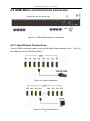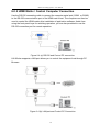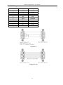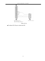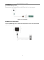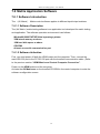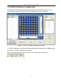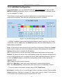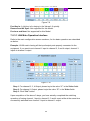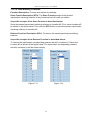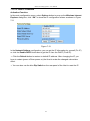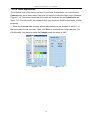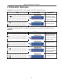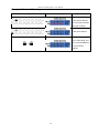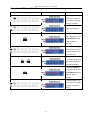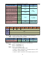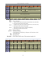
1
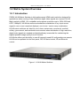
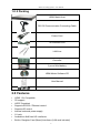
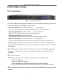
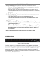
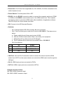
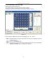
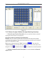
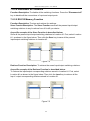
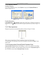
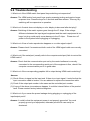
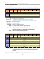
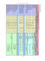
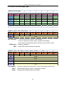
Matrix Switching System—User Manual User Manual Matrix Switcher HDMI 8x8 HX-88 V.2011HX88.00 Copyright and Trademarks: All rights reserved by ZIGEN INC. No part of this document may be reproduced in any form or by any means without written permission from the product manufacturer. Changes are periodically made to the information in this document. They will be incorporated in subsequent editions. The product manufacturer may make improvements and /or changes in the product described in this document at any time. All the registered trademarks referred to this manual are belonging to their respective companies. 0 Matrix Switching System—User Manual Before You Begin Follow all instructions marked on the device during using. Do not attempt to maintain the device yourself. Provide proper ventilation and air circulation and do not use near water. The system should be installed indoor only. Install either on a sturdy rack or desk in a well-ventilated place. Do not use liquid cleaners to clean the device. Always unplug the power to the device before cleaning. Unplug the power cord during lightning or after a prolonged period of non-use to avoid damage to equipment. Table of Contents 1 Matrix Switching System—User Manual 1.0 Matrix System Overview .......................................................................................................... 4 1.0.1 Introduction .................................................................................................................... 4 1.0.2 Packing ........................................................................................................................... 5 2.0 Features ..................................................................................................................................... 5 3.0 Specifications ............................................................................................................................ 6 4.0 Host Installation ........................................................................................................................ 6 5.0 Front/Rear Panels ...................................................................................................................... 7 5.0.1 Front Panel ..................................................................................................................... 7 5.0.2 Rear Panel ...................................................................................................................... 8 6.0 HDMI Matrix and Peripherals Connection ............................................................................. 11 6.0.1 Input/Output Connections ............................................................................................ 11 6.0.2 HDMI Matrix / Control Computer Connection............................................................ 12 6.0.3 IR2 Connection ............................................................................................................ 15 6.0.4 Power connection ......................................................................................................... 15 7.0 Matrix Application Software ................................................................................................... 16 7.0.1 Software Introduction ................................................................................................... 16 7.0.1.1 Software Description ......................................................................................... 16 7.0.1.2 Software Activation ........................................................................................... 16 7.0.2 RS-232 Software Configuration ................................................................................... 17 7.0.2.1 RS-232 Main Operation Interface ..................................................................... 18 7.0.2.2 Disconnect Function Keys ................................................................................ 20 7.0.2.3 Select all output, DeSelect all output Switching Functions .............................. 21 7.0.2.4 Disconnect all Command .................................................................................. 22 7.0.2.5 RS-232 Memory Function ................................................................................. 22 7.0.2.6 Options Function ............................................................................................... 23 7.0.2.7 Other Application .............................................................................................. 23 7.0.2.8 Communication Protocol/Control Command Code .......................................... 23 7.0.3 LAN Web Configuration .............................................................................................. 24 7.0.3.1 LAN Main Operation Interface ......................................................................... 25 7.0.3.2 LAN Memory Function ..................................................................................... 26 7.0.3.3 LAN IP Function ............................................................................................... 27 7.0.3.4 Other Application .............................................................................................. 28 8.0 Operation Examples ................................................................................................................ 29 9.0 Troubleshooting ....................................................................................................................... 32 Appendix A Command List ........................................................... Error! Bookmark not defined. 2 Matrix Switching System—User Manual 1.0 Matrix System Overview 1.0.1 Introduction ZIGEN HX-88 Matrix Switcher is high performance HDMI matrix switcher designed for applications where routing of high resolution digital video signals are required. HX-88 Matrix switch is HDMI 1.3c compatible and supports resolutions up to 1920x1200 and HDTV 1080p/60, HX-88 also ensures simultaneous distribution of any input source signal to one or more compliant displays.( one-to-one / one-to-many combination) HX-88 matrix switchers are ideal for use in bars, restaurants, commercial, medical, military, government, and residential environments where distribution of high resolution, digital video signals are needed and digital pathway is essential for maintaining the highest possible image quality from all sources. HX-88 also offers you the ability to save 8 frequently used I/O configurations as presets. HX-88 can be operated via the front panel, RS-232 serial control, IR and Ethernet control. Figure 1-1 HX-88 Matrix Switcher 4 Matrix Switching System—User Manual 1.0.2 Packing HDMI Matrix Host RS-232 Communication Connecting Cable Power Cord IR Extended Line LAN Line Controller 2 pcs of AAA battery HDMI Matrix Software CD User Manual 6 Screws (for Brackets) 2.0 Features HDMI 1.3c Compatible 3D support HDCP Compliant Supports RS-232 / Ethernet control Supports IR control Internal universal power supply 1U rack Available in 8x8 fixed I/O interfaces. Built-in Daughter Card (Board) Interfaces (LAN card included) 5 Matrix Switching System—User Manual Supports computer video up to 1920*1200 Supports HDTV up to 1080p/60 EDID management (Copy from OUT port 1) 3.0 Specifications Function HX-88 Input Connector 8 x HDMI Type A Output Connector 8 x HDMI Type A RS-232 Connector DB9 Female LAN Connector RJ-45 Select Switch 21 LCD Module 1 Max. Resolution 1080P Highest TMDS Frequency 225 MHz HDMI Cable Distance 10 meter (Max.) Power 100~240VAC, 50~60Hz, internal Housing Metal Weight 2350 g Dimensions (LxWxH) 440x336x43mm 4.0 Host Installation The HDMI Series Matrix Host has a black metallic housing. It can be placed on a sturdy desk directly or installed on a 19-in rack. See Figure 4-1 below: Figure 4-1 Mount the HDMI Matrix Host on a Standard Bracket 6 Matrix Switching System—User Manual 5.0 Front/Rear Panels 5.0.1 Front Panel Figure 5-1 HX-88 Front Panel The HX-88 Matrix Switching System supports up to 8 Output/Input switching keys on the Front Panel allowing you to switch signals quickly. Operation method No. 1: “Output Channel”+“Input Channel” Click the Output button then click the Input button to set the combinations. Operation method No. 2: “STO or RCL”+“Output Channel” Click the STO or RCL button then click the Output button. Operation method No. 3: single operation This example for EDID button, you can click the EDID button directly. Operation method No. 4: “STO and RCL”+“Input Channel” Click the STO and RCL button then click the Input button to set the combinations. OUT1~8 keys (output channel): Indicate the Channel 1~Channel 8 for HDMI singal output to peripheral display. You can also use these keys to adjust the status or access the settings IN1~8 keys (input channel): Indicate the Channel 1~Channel 8 for HDMI singal input. You can use these keys to switch to the connection of the connected signal source channels. IR1: Infrared receiver. All: This key allows you to set single input channel to all output channels. - Press the “All” key. - Select one of the IN 1~8 keys. - The selected IN x key will deliver the singal to all output channels. - You can also press “All” key and then the “OFF” key to disable all displays. OFF: Disable the entire output channels. Press one of the OUT x keys that you want to disable. 7 Matrix Switching System—User Manual STO: The “Store Key” saves all current input/output corresponding relations. - Press the “STO” key. (Supports up to 8 sets of memories, you can select the memory location through OUT1~OUT8) - Arrang the Output and Input channel combinations (output channel key 1~8). The relation between the Output and Input settings will be saved in the memory permanently. RCL: The “Retriever Key” retrieves the saved input/output corresponding relations. - Press the “RCL” key. - Then make a selection from one of the output channel key 1~8. - The system will retrieve the saved input/output status and implement current staus switching. EDID: FIX (fix mode) and TV1 (access the first output channel) selection key. - FIX mode: The HX-88 will supply a set of fixed EDID values to support up to only 1080P high performance TV. - TV1 mode: The HX-88 will accecc the EDID values of high performance TV that is connected to the first output channel, and copy the EDID value to all the input channels so that the DVD players and etc can support the same values to all HDTV monitors. LCD: LCD display shows current HDMI matrix status and operation status. 5.0.2 Rear Panel Figure 5-2 HX-88 Rear Panel The HX-88 supports up to 8 input/output connectors on the rear panel, each female terminals form the signal input/output connectors. The HX-88 signal input/output terminal channels are numbered from right to left as OUT1~4 / IN1~8 / OUT5~8 channels. The input terminal channels supply you to connect to different equipment including DVD players and graphics workstations. The output terminals can be connected to projectors, video recorders, HD displays and etc. 8 Matrix Switching System—User Manual Power Port: The Power Port is applicable for 100~240VAC, 50~60Hz connected to the outlet of power source. Power Switch: To switch power ON or OFF RS-232: Use the RS-232 connection cabel to connect the computer serial port (COM1 or COM2) to the RS232 communication port of the HDMI matrix host. The computer can then be used to control the HDMI matrix after installation of application software. The RS-232 port is a 9-pin female connector. IR2: Connect to the IR Extended Receiver. Switcher: - - Pin1: Switch between RS-232 port and LAN port connection. Pin2: This Pin allows you to reset the IP value to 192.168.0.3. The steps are as below: a. Please switch the pin2 down and re-start HX-88. b. After the HX-88 re-starts about 10sec, shut down your equipment. c. Switch the pin2 up, then power on HX-88 again. d. The IP address will be restored to the default value: 192.168.0.3 Pin3: No definition. Pin # UP DOWN 1 LAN RS-232 2 NORMAL IP DEFAULT 3 NC NC LAN Port: Use the RJ-45 connection cable to connect the Internet and the HDMI matrix host. All PC’s in the same network can control the HDMI matrix host through the LAN port. IN1~8: HDMI input ports are connected to DVDs. OUT1~8: HDMI output ports are connected to HDTVs. Daughter board modules: MX-HDI1 HDMI Connector input MX-HDO1 HDMI Connector output 9 Matrix Switching System—User Manual HDMI Type A Connector pin definition: Pin # Signal Pin # Signal 1 TMDS Data2+ 11 TMDS Clock Shield 2 TMDS Data2 Shield 12 TMDS Clock- 3 TMDS Data2- 13 NC 4 TMDS Data1+ 14 NC 5 TMDS Data1 Shield 15 DDC-SCL 6 TMDS Data1- 16 DDC-SDA 7 TMDS Data0+ 17 DDC-Ground 8 TMDS Data0 Shield 18 +5V Power 9 TMDS Data0- 19 Hot Plug Detect 10 TMDS Clock+ 10 Matrix Switching System—User Manual 6.0 HDMI Matrix and Peripherals Connection Figure 6-1 HDMI Matrix System Connections 6.0.1 Input/Output Connections Use the HDMI connecting cable to connect the Input/Output serial port (No.1 ~ No.8) to the HDMI port of the DVD Player/HDTV. Figure 6-2 Input Connections Figure 6-3 Output Connections 11 Matrix Switching System—User Manual 6.0.2 HDMI Matrix / Control Computer Connection Use the RS-232 connecting cable to connect the computer serial port (COM1 or COM2) to the RS-232 communication port of the HDMI matrix host. The computer can then be used to control the HDMI matrix after installation of application software. Aside from using the front panel keys for switching operation, you are also permitted to use the RS-232 connection port for remote operation. Figure 6-4 (a) RS-232 and Control PC connection HX-88 also supports a LAN port allows you to control the equipment host through PC Browser. Figure 6-4 (b) LAN port and Control PC Connection 12 Matrix Switching System—User Manual The RS-232 Leg functions are described as below: Pin No. Leg Description 1 N/u Null 2 Tx Send 3 Rx Receive 4 N/u Null 5 Gnd Ground 6 N/u Null 7 N/u Null 8 N/u Null 9 N/u Null Figure 6-5 Figure 6-5 (a) 13 Matrix Switching System—User Manual Figure 6-5 (b) The Matrix RS-232 port is defined as DCE. 14 Matrix Switching System—User Manual 6.0.3 IR2 Connection Please connect the Extended IR Line to the IR2 port that is on the rear panel. Figure 6-6 IR Connection 6.0.4 Power connection Use the included power cord to connect from the power port on the rear panel of HDMI matrix host to the outlet. Figure 6-7 Power Connection 15 Matrix Switching System—User Manual 7.0 Matrix Application Software 7.0.1 Software Introduction The 《AV Matrix》 Matrix control software applies to different input/output matrixes. 7.0.1.1 Software Description The《AV Matrix》matrix testing software is an application tool developed for matrix testing and application. The software operation environment is as follows: Window98/2000/7/NT/XP/Vista/ operatng systems 32M interal memory or above 10M hard disk space or above CD-ROM At least one serial communication port 7.0.1.2 Software Activation First, you must power off both the HDMI matrix and the computer. Then, connect the matrix RS-232 port to the PC RS-232 port with the bundled communication cable. (Refer to the previous section “HDMI Matrix and Control Computer Connection”. Power on the HDMI matrix and the computer: Activate the AV Matrix.exe on the bundled CD-ROM in the control computer to enter the software configuration screen. 16 Matrix Switching System—User Manual 7.0.2 RS-232 Software Configuration The software controls signal connection between the corresponding input port and output port as required. The RS-232 main configuration screen is as below: Figure 7-1 RS-232 Software Configuration Screen HX-88 is integrated Video/Audio switching equipment; please select the Video check box before you begin to operate the software. Scroll on the left area of the main screen to view contents as shown below. 17 Matrix Switching System—User Manual 7.0.2.1 RS-232 Main Operation Interface Refer to the main configuration screen as above, the marked blue area shows crossing matrix of output ports 01-08 and input ports 01-08. For basic operation, see described as below: Examples for Selecting Matrix Switching Functions: Example: Now there is an HX-88 matrix having all the input/output ports properly connected to the equipment. If you want to set channel 1 input to channel 2, 3 and 4 output; channel 3 inputs to channel 1 output. There are 2 ways to implement the switching. Please follow the directions and steps to finish the switching functions: First way: Make sure you have selected “Video” check box ( the corresponding icons on the matrix to transform them into ). Directly click on to complete the switching operation. Second way: Step 1: Make sure you have selected “Video” check box ( ). Step 2: First select the “Output”number keys 02, 03 and 04 to the right of the blue configuration area, and select the “Input” number key 01 to the bottom. Then, press consecutively the previously selected “Output” number keys 02, 03 and 04 (or you can press the “Deselect all output” key). This way, you have selected “Input” 01 and “Output” 02, 03 and 04 switching. Step 3: First select the “Output” number key 01 to the right of the blue configuration area, and select the “Input” number key 03 to the bottom. Then, press the previously selected “Output” number key 01 (or you can press the “Deselect all output” key). This way, you have selected Input 03 and Output 01 switching. Upon completion of the above 3 steps, you have actually completed the switching operation of having channel 1 input to channel 2, 3 and 4 ouput while at the same time successfully switched from channel 3 input to channel 1 output. The main configuration screen also shows you some function buttons for easy operation: Disconnect: To disable the connections. After you had configured the connection between input and output ports, you can click this button to disable the connections. Select all output: Click this button to select all output ports including output 01~08. Deselect all output: Click this button to cancel presently selected output ports. After you had configured a connected combination, please click this button first for next settings. Disconnect all: To stop all the connections. Scan: To search the host controlled by the RS-232 Software Configuration. When the host name located on the left of the main configuration screen is empty, you can click the 18 Matrix Switching System—User Manual Scan to research and update the host Name and ID. Options: Allows you to configure the Port number and Baud rate. Exit: Click this button to exit the configuration screen. Save: Click this button to save the connected combinations both output ports and input ports. Load: Click this button to retrieve the previously saved settings. For more information and operations, please refer to next chapters. 19 Matrix Switching System—User Manual 7.0.2.2 Disconnect Function Keys Disable all the unused output ports. A specific example of operation is described as below: The present input and output relations are shown in Figure 7-2 below: Figure 7-2 First you have to disable the output ports including port 03、02、and 01. Step 1: First press down the output number keys 03, 02 and 01 to the right of the blue configuration area. Step 2: Press the “Disconnect” key; Step 3: Press the previously pressed output number keys 03, 02 and 01 (or press the “Deselect all output” key) to complete the operation. 20 Matrix Switching System—User Manual The final results will be as shown in Figure 7-3 below: Figure 7-3 7.0.2.3 Select all output, DeSelect all output Switching Functions (1)Select all output Function Description: You can use this function to select all output ports and rout them to one input port. A specific example of operation is described below: Example: Now, you have an HX-88 matrix with all input and output ports properly connected to the equipment. The needed input/output ports should be set to channel 1 input to all output-ports to output. Make sure you have selected the “Video” check box ( ). Then, press the “Select all output” key and select the input number key 01. Click on the matrix icons along the 01 row to transform them into to complete the command operation. (2)DeSelect all output Function Description: It is used to disable the Select all output function. 21 Matrix Switching System—User Manual 7.0.2.4 Disconnect all Command Function Description: To disable all the switching functions. Press the “Disconnect all” key to disable all the connections of input and output ports. 7.0.2.5 RS-232 Memory Function Function Description: To store and retrieve the settings. Store Functin Description: The Store Function saves all the present input/output switching relations to any Locations from #1 to #8 you desire. A specific example of the Store Function is described below: Store all the present input/output switching relations to Location #1. First, select Location #1, as shown in the figure below. Then click the Save key to save all the present input/output switching relations to Location #1. Figure 7-4 Retrieve Function Description: To retrieve the saved input/output switching relations. A specific example of the Retrieve Function is described below: To retrieve the input/output corresponding relations saved in Location #1. First, select Location #1 as shown in the figure below. Then click the Load key to retrieve all the Input / output corresponding relations stored in Location #1. , Figure 7-5 22 Matrix Switching System—User Manual 7.0.2.6 Options Function Activation Function: In the main configuration menu, select Options to pop up the Options Window as shown in Figure 7-6(a) Figure 7-6(a) Figure 7-6(b) Function Description: Linking Methods: In “Port number” select either COM1 port or COM2 port as shown in Figure 7-6(b); in “Baud rate” select 9600 for signal transmission as shown in Figure 7-6 (a) 7.0.2.7 Other Application Displays the presently saved switching status as shown in Figure 6-7 below: Figure 7-7 When input corresponding to Output is enabling, it shows the Output ports corresponding to the Input ports; when they are disable it will show red “None” in the relative field. 7.0.2.8 Communication Protocol/Control Command Code Communication Protocol: Baud rate 9600bps, no odd or even calibration bit address, 8bit transmission address, 1bit stop address. Please refer to the “Command list.pdf” in the CD-ROM for more relative Command Code information. 23 Matrix Switching System—User Manual 7.0.3 LAN Web Configuration Open the Browser, key in the default IP address: http://192.168.0.3 to login the AV MATRIX Control configuration screen. Once the default IP address is changed, please use the changed IP to login. The software controls signal connection between the corresponding input port and output port as required. The LAN main configuration screen is as below: Figure 7-8 LAN Web Configuration Screen HDMI is integrated Video/Audio switching equipment; please only key in the Output Channel No. into the Video field, the Audio field value will be a default depends on the Video value automatically. Scan: To search the host controlled by the LAN Web Configuration. When the Console List content is empty, you can click the Scan to research and update the Console List. Options: Allows you to configure the IP address. Set: Click this button to set the connected combinations both output and input ports. Refresh: To refresh the values of the configuration screen. Any changed settings directly on the HX-88 equipment will not respond to the AV Matrix operating interface, you have to click the Refresh button to refresh the configuration screen so that it shows the changed values. OFF: Disable the entire output channels. STO: The “Store Key” saves all current input/output corresponding relations. RCL: The “Retriever Key” retrieves the saved input/output corresponding relations. For more relatived information, please refer to 5.0.1. Front Panel. All Output: A Hot Key for you to set the same value to all output channel. Select the All Output check box, then key in example “5” value in the channel 1 output. Click anywere on the screen, the all channel outputs will become “5” value. 24 Matrix Switching System—User Manual Figure 7-9 Port Key In: A Hot key is for keying in the Values1~8 quickly. Reserve and AV Sync: Not supported for this Model. Previous and Next: Not supported for this Model 7.0.3.1 LAN Main Operation Interface Refer to the main configuration screen as above, for the basic operation see described as below: Example: HX-88 matrix having all the input/output ports properly connected to the equipment. If you want to set channel 1 input to channel 2, 3 and 4 output; channel 3 inputs to channel 1 output. Figure 7-10 Step 1: For channel 2, 3, 4 Output, please keyin the value “1” in the Video fields. Step 2: For channel 1 Output, please keyin the value “3” in the Video fields. Step 3: Click “Set” button. Upon completion of the above 3 steps, you have actually completed the switching operation of having channel 1 input to channel 2, 3 and 4 ouput while at the same time successfully switched from channel 3 input to channel 1 output. 25 Matrix Switching System—User Manual 7.0.3.2 LAN Memory Function Function Description: To store and retrieve the settings. Store Functin Description (STO): The Store Function saves all the present input/output switching relations to any Locations from #1 to #8 you desire. A specific example of the Store Function is described below: Store the present input/output switching relations to Location #2. First, select Location #2, as shown in the figure below. Then click the STO button to save the present input/output switching relations to Location #2. Retrieve Function Description (RCL): To retrieve the saved input/output switching relations. A specific example of the Retrieve Function is described below: To retrieve the input/output corresponding relations saved in Location #1. Select the Location #1 as shown in the figure below. The input/output corresponding relations stored in Location #1 will be shown directly. Figure 7-11 Figure 7-12 26 Matrix Switching System—User Manual 7.0.3.3 LAN IP Function Activation Function: In the main configuration menu, select Options button to prop up the Windows Internet Explorer dialog box, click “OK” to show the IP configuration screen as shown in Figure 7-11 Figure 7-13 In the Network Settings configuration, you can set the IP information by yourself (Fix IP) or click the Enable DHCP check box to get the IP from the DHCP (Float IP). Click the Default button to restore to default IP address. After changing the IP, you have to restart (power off then power on) the Host to make the changed values take effect. You can also use the blue Dip Switch on the rear panel of the Host to reset the IP. 27 Matrix Switching System—User Manual 7.0.3.4 Other Application The software utility will show you at least 32 unit host ID and Name. You can click the Console down list to select which Host that you want to configure output /input values as Fiugure 7-14. The entire connected Host name will be shown on the Console List as figure 7-15. For this model, the software utility only shows an ID:00 for the Name: HX-88 presently. When the Console List is empty, please pay attention to the location of switch 1 on the rear panel of Host is correct. Then, click Scan to research the configured Host. For HX-88 model, only have to make the Console down list value to “00”. Figure 7-14 Figure 7-15 28 Matrix Switching System—User Manual 8.0 Operation Examples Example 1: Switch the NO.1 input signal to the NO.2 output channel. Key LCD Display Operation 1. Press the NO.2 key of the output channel, then the input channels will begin to flicker. 2. Press the NO.1 key of the Input channel. Example 2: Switch the NO.1 and NO.2 input signals to each NO.1 and NO.2 output channels. Key LCD Display Operation 1. Press the NO.1 key of the output channel, then the input channels will begin to flicker. 2. Press the NO.1 key of the Input channel. 3. Press the NO.2 key of the output channe, then the input channels will begin to flicker. 4. Press the NO.2 key of the Input channel. 29 Matrix Switching System—User Manual Example 3: Delete “All” settings. Key LCD Display Operation 1. Press the NO.2 key of the output channel, then the input channels will begin to flicker. 2. Press the NO.1 key of the Input channel. 3. Press the ALL key on the front panel, and then press the OFF key to cancel all the settings. 30 Matrix Switching System—User Manual Example 4: “STO” and “RCL” functions. Key LCD Display Operation 1. Press the NO.2 key of the output channel, then the input channels will begin to flicker. 2. Press the NO.1 key of the Input channel. 3. Press the STO key on the front panel. The Store Memory begins to flicker about 8 seconds. 4. Press the NO.1 key of the output channel to save the setting in the NO.1 channcel. 5. Press the ALL key on the front panel, and then press the OFF key to cancel the setting. 6. Press the RCL key on the front panel, The Recall Memory begins to flicker about 8 seconds. 7. Press the NO.1 key of the output channel to Load the previously saving. 31 Matrix Switching System—User Manual 9.0 Troubleshooting 1. What to do if the HDMI matrix front panel keys switching not responsive? Answer: The HDMI matrix front panel keys employ scanning testing and require longer response time. Press the keys for 2 seconds and then release. This way, key switching will be responsive in operation. 2. What to do if matrix does not display or color display is abnormal after hot plug? Answer: Switching of the matrix system goes through the IC chips. If the voltage difference between the input signal equipment and the matrix equipment is too large, hot plug could easily cause damage to the IC chips. power to the system before plugging or unplugging. Please turn off 3. What to do if loss of color reproduction happens or no video signal output? Answer: Please check if connectors at both ends of the HDMI signal cable are correctly connected. 4. What to do if the serial port (usually refer to the computer serial port) fails to control the HDMI matrix? Answer: Check that the communication port set by the control software is correctly connected to the corresponding serial port of the equipment. Also, check if the computer communication port is in good order. 5. What to do if the corresponding graphics fail to output during HDMI matrix switching? Answer: (1) Check if there is signal on the input end. If there is no input signal, it could be that the input connection cable is broken. You are advised to replace the connection cable. (2) Check if the output port number is the same as the controlled port number. (3) If none of the above circumstances happen, it could be internal failure of the product itself. Please contact factory technical engineer. 6. What to do if you sense the power leakage during plugging or unplugging of the input/output ports? Answer: It could be that the equipment power is not properly grounded. You must properly ground your equipment; otherwise product life can easily be shortened. 32 Matrix Switching System—User Manual 7. What to do if the LCD displays normally and the communication port has return code but no image output? Answer: (1) It could be that the output/input connectors got loosen. Simply replace the connectors. (2) It could be the connection cable short-circuited. Simply replace the cable. (3) It could be the connection cable is broken. Simply replace the cable. 8. What to do if the HDMI matrix panel keys and communication ports are out of order? Answer: Check if the equipment power input is in good contact and the computer communication ports are in good order. Please contact factory technical engineer. 9. What to do if operation and function failure occurred? Answer: Check if the equipment and the matrix switch are properly connected. If the problem persists, please contact factory technical engineer. 33 Matrix Switching System—User Manual Appendix A Command List AV Matrix Protocol v2.0 A-1 Host Request Table A-2 Device Acknowledge Type 34 Matrix Switching System—User Manual A-1 Host Request Table This RS-232 / RS-485 communication protocol uses five bytes of information as defined below. Host Target + Request + Index + Value + CRC Name Bit 7 Bit 6 Bit 5 Target BT 0 1 Request VAR 0 Bit 4 Bit 3 Bit 2 Bit 1 Bit 0 Device ID (0 - 31) Request (0 - 63) Index Index Value Value CRC CRC BT : 0: Instruction for device ID only. (Broadcast) 1: Instruction for all devices. (Device ID must be written 0) ※Devices will not response, when receiving the broadcast request. 0 (Reserve) : 1 (Identifier) : Device ID : VAR : (variable) CRC : Reserve, Always 0. Identifier, Always 1. Device id ranges from 0 to 31. 0: Normal length command. (Recommended) 1: Variable length command. (Only support the command is Ack Type A) If the VAR (variable) is 1, please refer to the table below. Send CRC code to follow the last byte. Variable Target + Request + LB + Index1 + Value1 + Index2 + Value2 + ..... + CRC Name Bit 7 Bit 6 Bit 5 Target BT 0 1 Request VAR 0 Bit 4 Bit 3 Bit 2 Bit 1 Bit 0 Device ID (0 - 31) Request (0 - 63) LB Length Index 1 Index 1 Value 1 Value 1 … …… Index n Index n Value n Value n CRC CRC LB (Length) : LB value is equal to the total (Index + Value). Not include the CRC byte. The default maximum length is 128. (If the extended information does not exist.) ※The default baud rate is 9600, with no parity, 8 data bits and 1 stop bit. 35 Matrix Switching System—User Manual 36 Matrix Switching System—User Manual 37 Matrix Switching System—User Manual A-2 Device Acknowledge Type Device ACK Type The device returns an acknowledge packet as defined below. Ack Type Byte 1 Byte 2 Byte 3 Byte 4 Byte 5 Byte 6 ..... Last Byte Type A ACK Type B ACK LB Index1 Value1 Type C ACK LB Data1 Data2 Type D ACK LB INF OP IP Mn1 ..... CRC Type E ACK LB EXTI VIDI AUDI PLUG ..... CRC Bit 2 Bit 1 Bit 0 CRC Index2 Value2 ..... CRC CRC ※ The device is always send the CRC code to follow the last byte. Type A ACK + CRC (Total 2 Bytes) Name Bit 7 Bit 6 Bit 5 ACK ACC 0 0 Bit 4 Bit 3 Device ID (0 - 31) CRC CRC ACC (Accept) : 1: Device accepts this request. (acknowledge) 0: Device rejects this request. (NAK; negative acknowledge) ※The device sends the Nak packet is always 2 bytes. (NAK + CRC) 0 (Reserve) : CRC : Type B Reserve, Always 0. Send CRC code to follow the last byte. ACK + LB + Index1 + Value1 + Index2 + Value2 + ..... + CRC Name Bit 7 Bit 6 Bit 5 ACK ACC 0 0 Bit 4 Bit 3 Bit 2 Bit 1 Bit 0 Device ID (0 - 31) LB Length Index N Index Value N Value … …… CRC CRC LB (Length) : LB value is equal to the total (Index + Value). Not include the CRC byte. Index : Often means that the input or output port number. Value : Response the status refers to the table. 38 Matrix Switching System—User Manual Request Description Request Request Status of Video Output 0x07 Request Status of Audio Output 0x08 Request Video Input Plug Status 0x09 Request Audio Input Plug Status 0x0A Request Video Output Plug Status 0x0B Request Audio Output Plug Status 0x0C Request Audio Mute Status 0x11 Request Audio Volume Level 0x13 Request Audio Bass Level 0x15 Request Audio Treble Level 0x17 Request Audio Subwoofer Level 0x19 Request EDID Type 0x21 Type C Index Value Output Input Input 1: Plug 0: Unplug Output 0: Unmute, 1: Mute Output Level Range (0 - 100) Input 0: Default, 1: Output 1 ACK + LB + Data1 + Data2 + CRC (Total 5 Bytes) Name Bit 7 Bit 6 Bit 5 ACK ACC 0 0 Bit 4 Bit 3 Bit 2 Bit 1 Bit 0 Device ID (0 - 31) LB Length Data1 Data 1 Data2 Data 2 CRC CRC LB (Length) : LB value is always 2 (Data1 + Data2). Not include the CRC byte. Data : Response the data refer to the table Request Description Request Firmware Version Request 0x31 Data1 VerA VerB Data2 VerC F/W Version : Contains the VerA, VerB and VerC (ex: VerA.VerB.VerC) Data1 : Bit 7~4 : VerA (Range 0 - 9) Bit 3~0 : VerB (Range 0 - 9) Data2 : Bit 7~0 : VerC (Range 0 - 99) If the Data1 is 0x10 and Data2 is 0x07 => VerA = 1, VerB = 0 and VerC = 7, Firmware version is v1.0.07 If the Data1 = 0x23 and Data2 = 0x45 => VerA = 2, VerB = 3 and VerC = 69, Firmware version is v2.3.6 39 Matrix Switching System—User Manual Type D ACK + LB + INF + OP + IP + Mn1 + Mn2 + Mn3 + ..... + CRC Name Bit 7 Bit 6 Bit 5 ACK ACC 0 0 Bit 4 Bit 3 Bit 2 Bit 1 Bit 0 Device ID (0 - 31) LB Length INFO Audio Video Extend 0 Total Memory Location (0 - 15) OP Total Output Port IP Total Input Port Mn1 Device Name (ASCII code) … …… Mnx Device Name (ASCII code) CRC CRC LB (Length) : LB value is the total length, not include the ACK, LB and CRC byte. INFO : Device information Bit 7 : 1 - Support Audio switch tools request. (Request 0x02, 0x04, 0x06, 0x08) 0 - Not support Audio switch tools request. Bit 6 : 1 - Support Video switch tools request. (Request 0x01, 0x03, 0x05, 0x07) 0 - Not support Video switch tools request. Bit 5 : 1 - Extended information exists. (Request 0x3F[0x01]) 0 - Extended information does not exist. Bit 4 : Reserve, always 0. Bit 3~0 : Total Memory location. ※Request[Index], if 0x3F[0x01] => Request = 0x3F and Index = 0x01 OP : IP : Mn1~Mnx : Type E Total Output Port. Total Input Port. Device Name (ASCII code). (The maximum length is 16) ACK + LB + EXTI + VIDI + AUDI + PLUG + ..... + CRC Name Bit 7 Bit 6 Bit 5 ACK ACC 0 0 Bit 4 Bit 3 Bit 2 Bit 1 Bit 0 Device ID (0 - 31) LB Length EXTI LBMAX 0 0 0 0 0 0 FWVER VIDI EDID 0 0 0 0 0 0 0 AUDI 0 0 0 0 Subwoofer Treble Bass Volume PLUG 0 0 0 0 AOPD VOPD AIPD VIPD … …… CRC CRC 40 Matrix Switching System—User Manual EXTI : Device extended information INFO : Device information Bit 7 : LBMAX - defines the maximum LB value of the variable length command. 0 - The maximum LB is 128 Bytes. (default) 1 - The maximum LB is 254 Bytes. (255 is reserved) The LB value of the Ack packet is not limited by LBMAX. If the extended information does not exist, the default maximum length is 128. Bit 6~1 : Reserve, always 0. Bit 0 : 1 - Support Firmware version request. (Request 0x31) 0 - Not support Firmware version request. VIDI : Bit 7 : Bit 6~0 : AUDI : Bit 0 : Bit 1 : Bit 2 : Bit 3 : Bit 7~4 : Video Extend Information 1 - Support EDID type select request. (Request 0x20 - 0x21) 0 - Not support EDID type select request. Reserve, always 0. Audio Extend Information. 1 - Support Volume and Mute control. (Request 0x10 - 0x13) 0 - Not support Volume control. 1 - Support Bass control. (Request 0x14 - 0x15) 0 - Not support Bass control. 1 - Support Treble control. (Request 0x16 - 0x17) 0 - Not support Treble control. 1 - Support Subwoofer control. (Request 0x18 - 0x19) 0 - Not support Subwoofer control. Reserve, always 0. ※If the AUDI is not equal to 0, the device support Request 0x04[0x02] and 0x06[0x02]. PLUG : Bit 0 : Bit 1 : Bit 2 : Bit 3 : Bit 7~4 : Plug Detect Support Information. 1 - Support Video input plug detection. (Request 0x09) 0 - Not support Video input plug detection. 1 - Support Audio input plug detection. (Request 0x0A) 0 - Not support Audio input plug detection. 1 - Support Video output plug detection. (Request 0x0B) 0 - Not support Video output plug detection. 1 - Support Audio output plug detection. (Request 0x0C) 0 - Not support Audio output plug detection. Reserve, always 0. 41 Matrix Switching System—User Manual WARRANTY LIMITED WARRANTY – with the exceptions noted in the next paragraph, ZIGEN warrants the original purchaser that the equipment it manufactures or sells will be free from defects in materials and workmanship for a period of one year from the date of purchase. The proof of sale is required in order to claim warranty. Should this product, in ZIGEN’s opinion, prove defective within this warranty period, ZIGEN, at its option, will repair or replace this product without charge. Customers outside of US are responsible for shipping charges to and from ZIGEN. Any defective parts replaced become the property of ZIGEN. This warranty does not apply to those products which have been damaged due to accident, unauthorized alterations, improper repair, modifications, inadequate maintenance and care, or use in any manner for which the product was not originally intended for. Items integrated into ZIGEN products that are made by other manufacturers, notably computer hard drives and liquid crystal display panels, are limited to the term of the warranty offered by the respective manufacturers. Such specific warranties are available upon request to ZIGEN. ZIGEN makes no other representation of warranty as to fitness for the purpose or merchantability or otherwise in respect of any of the products sold. The liability of ZIGEN with respect to any defective products will be limited to the repair or replacement of such products. In no event shall ZIGEN be responsible or liable for any damage arising from the use of such defective products whether such damages be direct, indirect, consequential or otherwise, and whether such damages are incurred by the reseller, end-user or any third party. The information in this manual has been carefully checked and is believed to be accurate. However, ZIGEN assumes no responsibility for any inaccuracies that may be contained in this manual, even if advised of the possibility of such damages. The technical information contained herein regarding the features and specifications is subject to change without notice. 42