1
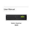
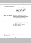
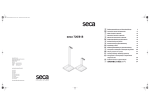
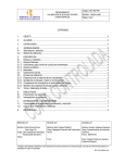
Matrix Switching System—User Manual User Manual Matrix Routing Switch HDMI 4x4 HX-44 V.2012HX44.00 Copyright and Trademarks: All rights reserved by ZIGEN INC. No part of this document may be reproduced in any form or by any means without written permission from the product manufacturer. Changes are periodically made to the information in this document. They will be incorporated in subsequent editions. The product manufacturer may make improvements and /or changes in the product described in this document at any time. All the registered trademarks referred to this manual are belonging to their respective companies. 0 Matrix Switching System—User Manual Before You Begin Follow all instructions marked on the device during using. Do not attempt to maintain the device yourself. Provide proper ventilation and air circulation and do not use near water. The system should be installed indoor only. Install either on a sturdy rack or desk in a well-ventilated place. Do not use liquid cleaners to clean the device. Always unplug the power to the device before cleaning. Unplug the power cord during lightning or after a prolonged period of non-use to avoid damage to equipment. 1 Matrix Switching System—User Manual Table of Contents 1.0 Matrix System Overview .......................................................................................................... 4 1.0.1 Introduction .................................................................................................................... 4 1.0.2 Packing ........................................................................................................................... 5 2.0 Host Installation ........................................................................................................................ 5 3.0 Specifications ............................................................................................................................ 6 4.0 Front/Rear Panels ...................................................................................................................... 6 4.0.1 Rear Panel ...................................................................................................................... 6 4.0.2 Rear Panel ...................................................................................................................... 8 5.0 HDMI Matrix and Peripherals Connection ............................................................................... 9 5.0.1 Input/Output Connections .............................................................................................. 9 5.0.2 HDMI Matrix and Control Computer Connection ....................................................... 10 5.0.3 IR2 Connection ............................................................................................................ 12 5.0.4 Power connection ......................................................................................................... 12 6.0 Matrix Application Software ................................................................................................... 13 6.0.1 Software Introduction ................................................................................................... 13 6.0.1.1 Software Description ......................................................................................... 13 6.0.1.2 Software Activation ........................................................................................... 13 6.0.2 Software Features ......................................................................................................... 14 6.0.2.1 Main Operation Interface Functions ................................................................. 15 6.0.2.2 Disconnect Function Keys ................................................................................ 17 6.0.2.3 Select all output, DeSelect all output Switching Functions .............................. 18 6.0.2.4 Disconnect all Command .................................................................................. 19 6.0.2.5 Memory Function .............................................................................................. 19 6.0.2.6 Options Function ............................................................................................... 20 6.0.2.7 Other Application .............................................................................................. 20 7.0 Operation Examples ................................................................................................................ 21 8.0 Communication Protocol/Control Command Code ................................................................ 23 9.0 Troubleshooting ....................................................................................................................... 23 Appendix A RS-232 Communication Protocol ............................................................................. 25 A-1 Host Request .................................................................................................................. 25 A-1.1 Device Byte ......................................................................................................... 25 A-1.2 Request Byte ....................................................................................................... 26 A-1.3 Index Byte ........................................................................................................... 28 A-1.4 Value Byte ........................................................................................................... 29 A-1.5 CRC Byte ............................................................................................................ 30 A-2 Device ACK Packet ....................................................................................................... 31 A-2.1 ACK Type A ........................................................................................................ 31 A-2.2 ACK Type B ........................................................................................................ 32 2 Matrix Switching System—User Manual A-2.3 ACK Type C ........................................................................................................ 33 A-2.4 ACK Type D ........................................................................................................ 34 A-2.5 ACK Type E ........................................................................................................ 35 3 Matrix Switching System—User Manual 1.0 Matrix System Overview 1.0.1 Introduction ZIGEN HX-44 Matrix Switcher is high performance HDMI matrix switcher designed for applications where routing of high resolution digital video signals are required. HX-44 Matrix switch is HDMI 1.3c compatible and supports resolutions up to 1920x1200 and HDTV 1080p/60, HX-44 also ensures simultaneous distribution of any input source signal to one or more compliant displays.( one-to-one / one-to-many combination) HX-44 matrix switchers are ideal for use in smaller bars, restaurants, commercial and residential environments where distribution of high resolution, digital video signals are needed and digital pathway is essential for maintaining the highest possible image quality from all sources. HX-44 can be operated via the front panel, RS-232 serial control or IR Figure 1-1 HX-44 Matrix 4 Matrix Switching System—User Manual 1.0.2 Packing HDMI Matrix Host RS-232 Communication Connecting Cable Adapter IR Extended Line Controller HDMI Matrix Software CD User Manual 2 Rack-Mount Bracket 6 Screws (for Brackets) 2.0 Host Installation The HDMI Series Matrix Host is made of metallic housing. It can be placed on a sturdy desk directly or installed on a 19-in bracket. See Figure 2-1 below: Figure 2-1 Mount the HDMI Matrix Host on a Standard Bracket 5 Matrix Switching System—User Manual 3.0 Specifications Function HX-44 Input Connector 4 x HDMI Type A Output Connector 4 x HDMI Type A RS-232 Connector DB9 Female Select Switch 13 LCD Module 1 Max. Resolution 1080P Highest TMDS Frequency 225 MHz HDMI Cable Distance 10 meter (Max.) Power Adapter (Min.) DC 12V Housing Metal Weight 2350 g Dimensions (LxWxH) 440x185x42mm 4.0 Front/Rear Panels 4.0.1 Rear Panel Figure 4-1 HX-44 Front Panel The HX-44 Matrix Switching System supports up to 4 Output/Input switching keys on the front Panel allow you to switch signals quickly. Operation methods as follows: “Output Channel”+“Input Channel” 6 Matrix Switching System—User Manual OUT 1~4 keys (output channel): Indicate the Channel 1~Channel 4 for HDMI signal output to peripheral display. You can also use these keys to adjust the status or access the settings IN 1~4 keys (input channel): Indicate the Channel 1~Channel 4 for HDMI signal input. You can use these keys to switch to the connection of the connected signal source channels. IR1: Infrared receiver. All: This key allows you to set single input channel to all output channels. - Press “All” key. - Select one of the IN 1~4 keys. - The selected IN x key will deliver the signal to all output channels. - You can also press “All” key and then the “OFF” key to disable all the displayed images. OFF: Disable the entire output channels. Press one of the OUT x keys that you want to disable, then press the OFF key. STO: The “Store Key” saves all current input/output corresponding relations. - Press the “STO” key. - Arrange the Output and Input channel combinations. - The relation between the Output and Input settings will be saved in the memory temporarily. RCL: The “Retriever Key” retrieves the saved input/output corresponding relations. - Press the “RCL” key. - Then press the previously saved output channel key The system will retrieve the saved input/output status and implement current status switching. EDID: FIX (fix mode) and TV1 (access the first output channel) selection key. - FIX mode: The HX-44 will supply a set of fixed EDID values to support up to 1080P high performance TV. - TV1 mode: The HX-44 will access the EDID values of high performance TV that is connected to the first output channel, and copy the EDID value to all the input channels so that the DVD player can support all the HDTV‟s. LCD: LCD display shows current HDMI matrix status and operation status. 7 Matrix Switching System—User Manual 4.0.2 Rear Panel Figure 4-2 HX-44 Rear Panel The HX-44 supports up to 4 input/output jacks on the rear panel, each 4th row HDMI female terminals form the signal input/output jacks. RS-232: Use the RS-232 connection cable to connect the computer serial port (COM1 or COM2) to the RS232 communication port of the HDMI matrix host. The computer can then be used to control the HDMI matrix after installation of application software. The RS-232 port is a 9-pin female connector. DC 12V: The Power is applicable for DC12V IR2: Connect to the IR Extended Receiver. INPUT 1~4: HDMI input Channels for source devices OUTPUT 1~4: HDMI output Channels HDTV‟s or Monitors. HDMI Type A Connector pin definition: Pin # Signal Pin # Signal 1 TMDS Data2+ 11 TMDS Clock Shield 2 TMDS Data2 Shield 12 TMDS Clock- 3 TMDS Data2- 13 NC 4 TMDS Data1+ 14 NC 5 TMDS Data1 Shield 15 DDC-SCL 6 TMDS Data1- 16 DDC-SDA 7 TMDS Data0+ 17 DDC-Ground 8 TMDS Data0 Shield 18 +5V Power 9 TMDS Data0- 19 Hot Plug Detect 10 TMDS Clock+ 8 Matrix Switching System—User Manual 5.0 HDMI Matrix and Peripherals Connection Figure 5-1 HDMI Matrix System Connections 5.0.1 Input/Output Connections Use the HDMI connecting cable to connect the Input/Output port (No.1 ~ No.4) to the HDMI port of the DVD Player/HDTV. Figure 5-2 Input Connection Figure 5-3 Output Connection 9 Matrix Switching System—User Manual 5.0.2 HDMI Matrix and Control Computer Connection Use the RS-232 connecting cable to connect the computer serial port (COM1 or COM2) to the RS-232 communication port of the HDMI matrix host. The computer can then be used to control the HDMI matrix after installation of application software. Aside from using the front panel keys for switching operation, you are also permitted to use the RS-232 connection port for remote operation. Figure 5-4 HDMI Matrix and Computer Connection The Leg functions are described as below: Pin No. Leg Description 1 N/u Null 2 Tx Send 3 Rx Receive 4 N/u Null 5 Gnd Ground 6 N/u Null 7 N/u Null 8 N/u Null 9 N/u Null Figure 5-5 10 Matrix Switching System—User Manual Figure 5-5 (a) Figure 5-5 (b) The Matrix RS-232 port is defined as DCE. 11 Matrix Switching System—User Manual 5.0.3 IR2 Connection The HDMI matrix provides you an IR Extended Line for more convenient to react to the controller. Please connect the IR Extended Line to the IR2 port that is on the rear panel. Figure 5-6 IR Connection 5.0.4 Power connection Use the included adapter to connect from the power port on the rear panel of HDMI matrix host to the outlet. Figure 5-7 Power Connection 12 Matrix Switching System—User Manual 6.0 Matrix Application Software 6.0.1 Software Introduction The 《AV Matrix》 Matrix control software applies to different input/output matrixes. 6.0.1.1 Software Description The《AV Matrix》matrix testing software is an application tool developed for matrix testing and application. The software operation environment is as follows: Window98/2000/NT/XP operating systems 32M internal memory or above 10M hard disk space or above CD-ROM At least one serial communication port 6.0.1.2 Software Activation First, you must power off both the HDMI matrix and the computer. Then, connect the matrix RS-232 port to the PC RS-232 port with the bundled communication cable. (Refer to the previous section “HDMI Matrix and Control Computer Connection”. Power on the HDMI matrix and the computer: Activate the AV Matrix.exe on the bundled CD-ROM in the control computer to enter the software configuration screen. 13 Matrix Switching System—User Manual 6.0.2 Software Features The software controls signal connection between the corresponding input port and output port as required. The main configuration screen is shown below: Figure 6-1 《AV Matrix》Software Configuration Screen HX-44 is integrated Video/Audio switching equipment; please select the Video check box before you begin to operate the software. Scroll on the left area of the main screen to view contents as shown below. 14 Matrix Switching System—User Manual 6.0.2.1 Main Operation Interface Functions Refer to the main configuration screen as above, the marked blue area shows crossing matrix of output ports 01-04 and input ports 01-04. Basic operation is described as below: Example, Selecting Matrix Switching Functions: HX-44 matrix having all the input/output ports properly connected to the equipment. If you want to set channel 1 input to channel 2, 3 and 4 output; channel 3 input to channel 1 output. There are 2 ways to implement the switching. Please follow the ways and steps to finish the switching functions: First: Make sure you have selected “Video” check box ( corresponding icons on the matrix to transform them into ). Directly click on the to complete the switching operation. Second: Step 1: Make sure you have selected “Video” check box ( ). Step 2: Select the “Output” number keys 02, 03 and 04 to the right of the blue configuration area, and select the “Input” number key 01 below. Then, press consecutively the previously selected “Output” number keys 02, 03 and 04 (or you can press the “Deselect all output” key). This way, you have selected “Input” 01 and “Output” 02, 03 and 04 switching. Step 3: First select the “Output” number key 01 to the right of the blue configuration area, and select the “Input” number key 03 on the bottom. Then, press the previously selected “Output” number key 01 (or you can press the “Deselect all output” key). This way, you have selected Input 03 and Output 01 switching. Upon completion of the above 3 steps, you have actually completed the switching operation of having channel 1 input to channel 2, 3 and 4 output while at the same time successfully switched from channel 3 input to channel 1 output. The main configuration screen also shows you some function buttons for easy operation: Disconnect: To disable the connections. After you had configured the connection between input and output ports, you can click this button to disable the connections. Select all output: Click this button to select all output ports including output 01~04. Deselect all output: Click this button to cancel presently selected output ports. After you had configured a connected combination, please click this button first for next settings. Disconnect all: To stop feed to all connections. 15 Matrix Switching System—User Manual Scan: To refresh the values of the configuration screen. Any changed settings directly on the HX-44 equipment will not respond to the AV Matrix operating interface, you have to click the Scan button to refresh the configuration screen so that it may show the changed values. Options: Allows you to configure the Port number and Baud rate. Exit: Click this button to exit the configuration screen. Save: Click this button to save the connected combinations for both output ports and input ports. Load: Click this button to retrieve the previously saved settings. For more information and operations, please refer to next chapters. 16 Matrix Switching System—User Manual 6.0.2.2 Disconnect Function Keys Disable all the unused output ports. A specific example of operation is described as below: The present input and output relations are shown in Figure 6-2 below: Figure 6-2 First you have to disable the output ports including port 03、02、and 01. Step 1: First press down the output number keys 03, 02 and 01 to the right of the blue configuration area. Step 2: Press the “Disconnect” key; Step 3: Press the previously pressed output number keys 03, 02 and 01 (or press the “Deselect all output” key) to complete the operation. 17 Matrix Switching System—User Manual The final results will be as shown in Figure 6-3 below: Figure 6-3 6.0.2.3 Select all output, Deselect all output Switching Functions (1)Select all output Function Description: You can use this function to select all output ports to output one input port. A specific example of operation is described below: Example: Your HX-44 matrix with all input and output ports properly connected to the equipment. The needed input/output ports should be set to channel 1 input and sent to all output-ports. Make sure you have selected the “Video” check box ( ). Then, press the “Select all output” key and select the input number key 01. Click on the matrix icons along the 01 row to transform them into to complete the command operation. (2)Deselect all output Function Description: It is used to disable the Select all output function. 18 Matrix Switching System—User Manual 6.0.2.4 Disconnect all Command Function Description: To disable all switching functions. Press the “Disconnect all” key to disable all the connections of input and output ports. 6.0.2.5 Memory Function Function Description: To store and retrieve the settings. Store Function Description: The Store Function saves all the preset input/output switching relations to any Location from #1 to #4 you desire. A specific example of the Store Function is described below: Stores all the preset input/output switching relations to Location #1. First, select Location #1, as shown in the figure below. Then click the Save key to save all the preset input/output switching relations to Location #1. Figure 6-4 Retrieve Function Description: To retrieve the saved input/output switching relations. A specific example of the Retrieve Function is described below: To retrieve the input/output corresponding relations saved in Location #1. First, select Location #1 as shown in the figure below. Then click the Load key to retrieve all the input/output corresponding relations stored in Location #1. , Figure 6-5 19 Matrix Switching System—User Manual 6.0.2.6 Options Function Activation Function: In the main configuration menu, select Options to drop down the Options Window as shown in Figure 6-6(a) Figure 6-6(a) Figure 6-6(b) Function Description: Linking Methods: In “Port number” select either COM1 port or COM2 port as shown in Figure 6-6(b); in “Baud rate” select 9600 for signal transmission as shown in Figure 6-6 (a) 6.0.2.7 Other Application Displays the presently saved switching status as shown in Figure 6-7 below: Figure 6-7 When input corresponding to Output is enabled, it shows the Output ports correspond to the Input ports; when they are disabled, it will show red “None” in the relative field. 20 Matrix Switching System—User Manual 7.0 Operation Examples Example 1: Switch the NO.1 input signal to the NO.2 output channel. Key LCD Display Operation 1. Press the NO.2 key of the output channel for 2 seconds, then the input channels will begin to flicker. 2. Press the NO.1 key of the Input channel for 2 seconds. Example 2: Switch the NO.1 and NO.2 input signals to each NO.1 and NO.2 output channels. Key LCD Display Operation 1. Press the NO.1 key of the output channel for 2 seconds, then the input channels will begin to flicker. 2. Press the NO.1 key of the Input channel for 2 seconds. 3. Press the NO.2 key of the output channel for 2 seconds, then the input channels will begin to flicker. 4. Press the NO.2 key of the Input channel for 2 seconds. Example 3: Delete “All” settings. Key LCD Display Operation 3. Press the ALL key on the front panel, and then press the OFF key to cancel all the settings. 21 Matrix Switching System—User Manual Example 4: “STO” and “RCL” functions. Key LCD Display Operation 1. Press the NO.2 key of the output channel for 2 seconds, then the input channels will begin to flicker. 2. Press the NO.1 key of the Input channel for 2 seconds. 3. Press the STO key on the front panel, then the OUT channels will begin to flicker. 4. Press the NO.1 key of the output channel to save the setting in the NO.1 channel. 5. Press the ALL key on the front panel, and then press the OFF key to cancel the setting. 6. Press the RCL key on the front panel, then the OUT channels will begin to flicker. 7. Press the NO.1 key of the output channel to Load the previously saved. 22 Matrix Switching System—User Manual 8.0 Communication Protocol/Control Command Code Communication Protocol: Baud rate 9600bps, no odd or even calibration bit address, 8bit transmission address, 1bit stop address. Please refer to the “Command list.pdf” in the CD-ROM for more related Command Code information. 9.0 Troubleshooting 1. What do I do if the HDMI matrix front panel switching keys are not responding? Answer: The HDMI matrix front panel keys employ scanning testing and require longer response time. Press and hold the keys for 2 seconds. This will ensure key switching will be responsive in operation. 2. What do I do if matrix does not display or color display is abnormal after hot plug? Answer: Switching of the matrix system goes through the IC chips. If the voltage difference between the input signal equipment and the matrix equipment is too large, hot plug could easily cause damage to the IC chips. Please turn off the power to the system before plugging or unplugging. 3. What do I do if there is a loss of color reproduction, or no video signal output? Answer: Please check if connectors at both ends of the HDMI signal cable are correctly connected. 4. What do I do if the serial port (usually refer to the computer serial port) fails to control the HDMI matrix? Answer: Check that the communication port set by the control software is correctly connected to the corresponding serial port of the equipment. Also, check to see if the computer communication port is in good order. 5. What do I do if the corresponding graphics fail to output during HDMI matrix switching? Answer: (1) Check if there is signal on the input end. If there is no input signal, it could be that the input connection cable is broken or the connector gets loose. You are advised to replace the connection cable. (2) Check if there is signal on the output end. If there is no output signal, it could be that the cable is broken or the connector gets loose. You are advised to replace the connection cable. 23 Matrix Switching System—User Manual (3) Check if the output port number is the same as the controlled port number. (4) If none of the above circumstances happen, it could be internal failure of the product itself. 6. What do I do if I sense power leakage during plugging or unplugging of the input/output ports? Answer: It could be that the equipment power is not properly grounded. You must properly ground your equipment; otherwise product life can easily be shortened. 24 Matrix Switching System—User Manual Appendix A RS-232 Communication Protocol This AV Matrix RS-232 communication protocol uses fixed length with 5 bytes of information as define below. The default baud rate is 9600 bps, no parity, 8 data bit and 1 stop bit. Command timeout is 300ms, and byte to byte timeout is 30ms. Use the RS-232 connecting cable to connect the computer serial port to the RS-232 communication port of the Matrix device. The computer can control the Matrix device via RS-232. Aside from using the front panel keys for operation, you are also permitted to use the RS-232 connection port for remote operation. A-1 Host Request A standard command is 5 bytes: Device + Request + Index + Value + CRC Byte 1: Device Byte (DB) Byte 2: Request Byte (RB) Byte 3: Index Byte (IB) Byte 4: Value Byte (VB) Byte 5: CRC Byte (CB) Host must send CRC code to follow the last byte. A-1.1 Device Byte Name Bit 7 Bit 6 Bit 5 DB BT 0 1 Bit 4 Bit 3 Bit 2 Bit 1 Device ID (0 - 31) BT: Broadcast Command Flag. 0 - Instruction for Device ID only 1 - Instruction for all devices. (Device ID must be written 0) Devices will not response, when receiving the broadcast command. 0: Reserve, Always 0. 1: Identifier, Always 1. Device ID: Device id ranges from 0 to 31. (Please refer to device‟s user manual) 25 Bit 0 Matrix Switching System—User Manual A-1.2 Request Byte Request Byte (RB) Name Bit 7 Bit 6 RB 0 0 Bit 5 Bit 4 Bit 3 Bit 2 Bit 1 Bit 0 Request Type (0 - 63) 0: Reserve, Always 0. Request Type: Please refer to "Table - Host Request List". Table - Host Request List Request Type 0x00 Description Dummy call Index Value ACK Type Note - - A 1, 2 Switch Tools 0x01 Switch Video Output Channel Output Input A 2 0x02 Switch Audio Output Channel Output Input A 2 0x03 Store Video Status Setting Memory A 2, 3 0x04 Store Audio Status Setting Memory A 2, 3 0x05 Recall Video Status Setting Memory A 2 0x06 Recall Audio Status Setting Memory A 2 0x07 Request Video Output Channel Output Memory B 0x08 Request Audio Output Channel Output Memory B Plug Detect 0x09 Request Video Input Plug Status Input 0 B 0x0A Request Audio Input Plug Status Input 0 B 0x0B Request Video Output Plug Status Output 0 B 0x0C Request Audio Output Plug Status Output 0 B Audio Control 0x10 Control Audio Output Mute Output Enable A 0x11 Request Audio Output Mute Status Output Memory B 0x12 Control Audio Output Volume Output Level A 0x13 Request Audio Output Volume Output Memory B 0x14 Control Audio Output Bass Output Level A 26 2 2 2 Matrix Switching System—User Manual 0x15 Request Audio Output Bass Output Memory B 0x16 Control Audio Output Treble Output Level A 0x17 Request Audio Output Treble Output Memory B 0x18 Control Audio Output Subwoofer Output Level A 0x19 Request Audio Output Subwoofer Output Memory B 0x1C Control Audio Output Delay Low Output Delay1 A 0X1D Request Audio Output Delay Low Output Memory B 0X1E Control Audio Output Delay High Output Delay2 A 0X1F Request Audio Output Delay High Output Memory B 2 2 2 2 Video Control 0x20 Select Input EDID Type 0 EDID A 0x21 Request Input EDID Type 1 0 B 2 Device Information 0x30 Request Protocol Version 0 0 C 0x31 Request Firmware Version 0 0 C 0x3F Request Device Information 0 0 D 0x3F Request Extend Information 1 0 E 1 1 Command Note: 1. All devices support the command. 2. Support broadcast commands. 3. Memory # 0 is the current status, it can„t be stored. Memory #1 – 8 is allowed to be stored. 4. Use 0x3F to confirm the device connected is properly and supported commands. 27 Matrix Switching System—User Manual A-1.3 Index Byte Index Byte (IB) Name Bit 7 Bit 6 Bit 5 Bit 4 IB Bit 3 Bit 2 Bit 1 Bit 0 Index Index: Please refer to "Table - Host Request List" and "Table - Command Index List". Table – Command Index List Index Description Output The output that will be selected. (Port 1 = 1, Port 2 = 2… Port n = n) 0: All outputs Input Setting - The input that will be selected. (Port 1 = 1, Port 2 = 2… Port n = n) 0: All inputs The setting type that will be selected. 0: All Settings 1: Switch Settings only 2: Video/Audio Settings only Don‟t care 28 Matrix Switching System—User Manual A-1.4 Value Byte Value Byte (VB) Name Bit 7 Bit 6 Bit 5 Bit 4 VB Bit 3 Bit 2 Bit 1 Bit 0 Value Value: Please refer to "Table - Host Request List" and "Table - Command Value List". Table – Command Value List Value Description Input The input that will be connected. (Port 1 = 1, Port 2 = 2… Port n = n) 0: Disconnect Memory Select Memory Location 0 : Current Status (Can„t be stored) Enable 1: Enable Status (example: Mute, Plug) 0: Disable Status (example: Un-mute, Unplug) Level Delay Level Range (0 – 100) 0x81: Increase a step 0x82: Decrease a step Audio delay time is 16-bit data. (Unit: 5ms or 10ms) Delay1 - The audio delay time low byte. (Bit0 – Bit7) Delay2 - The audio delay time high byte. (Bit8 – Bit15) The audio delay time unit decided by the DTUF flag of the extend information. The maximum Delay decided by the DTMAX flag of the extended information. EDID - EDID Type 0: Fixed (Device default EDID) 1: Output 1 (Copy the EDID from the output 1) Don‟t care 29 Matrix Switching System—User Manual A-1.5 CRC Byte CRC Byte (CB) Name Bit 7 Bit 6 CB Bit 5 Bit 4 Bit 3 Bit 2 Bit 1 Bit 0 CRC (cyclic redundancy check) CRC: Host must send CRC code to follow the last byte. Table – CRC Table 00 01 02 03 04 05 06 07 08 09 0A 0B 0C 0D 0E 0F 00 00 5E BC E2 61 3F DD 83 C2 9C 7E 20 A3 FD 1F 41 10 9D C3 21 7F FC A2 40 1E 5F 01 E3 BD 3E 60 82 DC 20 23 7D 9F C1 42 1C FE A0 E1 BF 5D 03 80 DE 3C 62 30 BE E0 02 5C DF 81 63 3D 7C 22 C0 9E 1D 43 A1 FF 40 46 18 FA A4 27 79 9B C5 84 DA 38 66 E5 BB 59 07 50 DB 85 67 39 BA E4 06 58 19 47 A5 FB 78 26 C4 9A 60 65 3B D9 87 04 5A B8 E6 A7 F9 1B 45 C6 98 7A 24 70 F8 A6 44 1A 99 C7 25 7B 3A 64 86 D8 5B 05 E7 B9 80 8C D2 30 6E ED B3 51 0F 4E 10 F2 AC 2F 71 93 CD 90 11 4F AD F3 70 CC 92 D3 8D 6F 31 B2 EC 0E 50 A0 AF F1 13 4D CE 90 72 2C 6D 33 D1 8F 0C 52 B0 EE B0 32 6C 8E D0 53 0D EF B1 F0 AE 4C 12 91 CF 2D 73 C0 CA 94 76 28 AB F5 17 49 08 56 B4 EA 69 37 D5 8B D0 57 09 EB B5 36 68 8A D4 95 CB 29 77 F4 AA 48 16 E0 E9 B7 55 0B 88 D6 34 6A 2B 75 97 C9 4A 14 F6 A8 F0 74 2A C8 96 15 4B A9 F7 B6 E8 0A 54 D7 89 6B 35 2E Example: switch output 6 to the input 3. Byte 1 (DB) is 0x20 – Device: Identifier + Device ID = 0x20 + 0 = 0x20 Byte 2 (RB) is 0x01 – Request: Switch Video Output Channel = 0x01 Byte 3 (IB) is 0x06 – Index: Output 6 = 6 Byte 4 (VB) is 0x03 – Value: Input 3 = 3 Byte 5 (CB) is 0x93 – CRC code from Byte 1 to Byte 4. (CRC4) CRC Calculation CRC 0 = 0 (initial value) CRC 1 = CRC_ TABLE [CRC 0 ^ Byte 1] = CRC_ TABLE [0x00 ^ 0x20] = 0x23 CRC 2 = CRC_ TABLE [CRC 1 ^ Byte 2] = CRC_ TABLE [0x23 ^ 0x01] = 0x9F CRC 3 = CRC_ TABLE [CRC 2 ^ Byte 3] = CRC_ TABLE [0x9F ^ 0x06] = 0x8D CRC 4 = CRC_ TABLE [CRC 3 ^ Byte 4] = CRC_ TABLE [0x8D ^ 0x03] = 0x93 30 Matrix Switching System—User Manual A-2 Device ACK Packet When the device receives supported commands comes from the host, and then will response with following ACK: Table – ACK Type List Byte 2 Byte 3 Byte 4 Byte 5 Byte 6 … Ack Type Byte 1 Last Byte Type A AB Type B AB LB Index 1 Value 1 Type C AB LB Data 1 Data 2 Type D AB LB INF OP IP Name 1 … CB Type E AB LB EXINF VEINF AEINF PLUG … CB CB Index 2 Value 2 … CB CB A-2.1 ACK Type A ACK Byte + CRC Byte (Total 2 Bytes) Name Bit 7 Bit 6 Bit 5 AB ACC 0 0 Bit 4 Bit 3 Bit 2 Bit 1 Device ID (0 – 31) CB CRC ACC: The devices acknowledge status. Accept or Reject. 1: device accepts this request. (ACK; acknowledge) 0: device rejects this request. (NAK; negative acknowledge) The device sends the Nak packet is always 2 bytes. (NAK + CRC) 0: Reserve, Always 0. 1: Identifier, Always 1. Device ID: Device id ranges from 0 to 31. (Please refer to device‟s user manual) CRC: Device always sends the CRC code to follow the last byte. 31 Bit 0 Matrix Switching System—User Manual A-2.2 ACK Type B ACK Byte + LB + Index1 + Value1 + Index2 + Value2 +…..+ CRC Byte Name Bit 7 Bit 6 Bit 5 AB ACC 0 0 Bit 4 Bit 3 Bit 2 Bit 1 Bit 0 Device ID (0 – 31) LB Length for the total data bytes (Index + Value) IB n Index VB n Value … … CB CRC AB & CB: These are the same as the ACK Type A. LB: LB value is equal to the total data bytes (Index + Value), not include the CRC byte. The maximum LB value of the ACK Type B is twice the total number of output or input. IB: Often means that the input or output port number. (Port 1 = 1, Port 2 = 2… Port n = n) VB: Response the status refers to the table. Request Description Index Value Output Input 0x07 Request Video Output Channel 0x08 Request Audio Output Channel 0x09 Request Video Input Plug Status 0x0A Request Audio Input Plug Status 0x0B Request Video Output Plug Status 0x0C Request Audio Output Plug Status 0x11 Request Audio Output Mute Status 0x13 Request Audio Output Volume 0x15 Request Audio Output Bass 0x17 Request Audio Output Treble 0x19 Request Audio Output Subwoofer 0x1D Request Audio Output Delay Low Delay1 0x1F Request Audio Output Delay High Delay2 0x21 Request Input EDID Type Input Output Enable 1: Plug 0: Unplug 0: Un-mute, 1: Mute Output Input Level Range (0 – 100) EDID Type Please refer to “Table – Command Index List” and “Table – Command Value List”. 32 Matrix Switching System—User Manual A-2.3 ACK Type C ACK Byte + LB + Data 1 + Data 2 + CRC Byte (Total 5 Bytes) Name Bit 7 Bit 6 Bit 5 AB ACC 0 0 Bit 4 Bit 3 Bit 2 Bit 1 Bit 0 Device ID (0 – 31) LB Length for the total data bytes (This byte is always 2) DB 1 Data 1 DB 2 Data 2 CB CRC AB & CB: These are the same as the ACK Type A. LB: LB value is always 2 (Data 1 + Data 2). Not include the CRC byte. DB: Data Bytes as define below. Request Description 0x30 Request Protocol Version 0x31 Request Firmware Version Data 1 Data 2 VER1 VER2 VERA VERB VERC Version Type A: RS-232 Protocol Version contains the VER1 and VER2 (ex: VER1.VER2) VER1: Data 1, Bit 7 - Bit 0 (Range 0 - 99) VER2: Data 2, Bit 7 - Bit 0 (Range 0 - 99) If the Data 1 is 0x01 and Data 2 is 0x07; VER1 = 1 and VER2 = 7; RS-232 protocol version is v1.07 If the Data 1 = 0x23 and Data 2 = 0x45; VER1 = 0x23 = 35 and VER2 = 0x45 = 69; RS-232 protocol version is v35.69 Version Type B: Firmware Version contains the VERA, VERB and VERC (ex: VERA.VERB.VERC) VERA: Data 1, Bit 7 - Bit 4 (Range 0 - 9) VERB: Data 1, Bit 3 - Bit 0 (Range 0 - 9) VERC: Data 2, Bit 7 - Bit 0 (Range 0 - 99) If the Data 1 is 0x10 and Data 2 is 0x07; VERA = 1, VERB = 0 and VERC = 7; Firmware version is v1.0.07 If the Data 1 = 0x23 and Data 2 = 0x45; VERA = 2, VERB = 3 and VERC = 69; Firmware version is v2.3.69 33 Matrix Switching System—User Manual A-2.4 ACK Type D ACK Byte + LB + INF + OP + IP + Name 1 + Name 2 + Name 3 +.....+ CRC Byte Name Bit 7 Bit 6 Bit 5 AB ACC 0 0 LB Bit 4 Bit 3 Bit 2 Bit 1 Bit 0 Device ID (0 - 31) Length for the total data bytes (INFO +.....+ Name n) INFO Audio Video Extend 0 Total Memory Location (0 - 15) OP Total Output Port IP Total Input Port NB 1 Device Name (ASCII code) … … NB n Device Name (ASCII code) CB CRC AB & CB: These are the same as the ACK Type A. LB: LB value is the total length of the data bytes, not include the AB, LB and CB. The maximum LB value of the ACK Type D is 19. INFO: Device information Bit 7: 1 - Support Audio switch tools request. (Request 0x02, 0x04, 0x06 and 0x08) 0 - Not support Audio switch tools request. Bit 6: 1 - Support Video switch tools request. (Request 0x01, 0x03, 0x05 and 0x07) 0 - Not support Video switch tools request. Bit 5: 1 - Extended information exists. (Request 0x3F [0x01]) 0 - Extended information does not exist. Bit 4: Reserve, always 0. Bit 3~0: Total Memory location ranges from 0 to 15. Request [Index], if 0x3F [0x01] => Request = 0x3F and Index = 0x01 OP: The total number of output. IP: The total number of input. NB: Device Name (ASCII code). (The maximum length is 16) 34 Matrix Switching System—User Manual A-2.5 ACK Type E ACK Byte + LB + EXTI + VIDI + AUDI + PLUG +.....+ CRC Byte Name Bit 7 Bit 6 Bit 5 AB ACC 0 0 LB Bit 4 Bit 3 Bit 2 Bit 1 Bit 0 Device ID (0 - 31) Length for the total data bytes (EXINF +.....+ DTMAX) 0 0 0 0 0 FWVER VEINF LBMAX 0 EDID 0 0 0 0 0 0 0 AEINF DTUF DELAY 0 0 SW TRE BASS VOL PLUG 0 0 0 0 AOPD VOPD AIPD VIPD EXINF DTMAX Delay Time Maximum (unit: 100 ms) CB CRC AB & CB: These are the same as the ACK Type A. LB: LB value is the total length of the data bytes, not include the AB, LB and CB. EXINF: Device extended information LBMAX - defines the maximum LB value of the variable length command 0 - The maximum LB is 64 Bytes (default) 1 - The maximum LB is 128 Bytes 2 - The maximum LB is 254 Bytes (255 is reserved) 3 - Reserved The LB value of the Ack packet is not limited by LBMAX. If the extended information does not exist, the default maximum length is 128. FWVER - Firmware version command flag. (Request 0x31) 1 - Support Firmware version command. 0 - Not support Firmware version command. VEINF: Video Extend Information EDID - Input EDID type select command flag. (Request 0x20 and 0x21) 1 - Support Input EDID type select command. 0 - Not support Input EDID type select command. AEINF: Audio Extend Information VOL - Volume and Mute command flag. (Request from 0x10 to 0x13) 1 - Support Volume and Mute command. 0 - Not support Volume command. BASS - Bass command flag. (Request 0x14 and 0x15) 1 - Support Bass command. 0 - Not support Bass command. 35 Matrix Switching System—User Manual TRE - Treble command flag. (Request 0x16 and 0x17) 1 - Support Treble command. 0 - Not support Treble command. SW - Subwoofer command flag. (Request 0x18 and 0x19) 1 - Support Subwoofer command. 0 - Not support Subwoofer command. DELAY – Audio delay command flag. (Request from 0x1C to 0x1F) 1 - Support audio delay command. 0 - Not support audio delay command. DTUF - defines the audio delay time scale units. 1 - Audio delay time scale unit is 10ms 0 - Audio delay time scale unit is 5ms (default) If the AEINF is not equal to 0, the device support Request 0x04[0x02] and 0x06[0x02]. PLUG: Plug Detect Support Information. VIPD - Video input plug detection command flag. (Request 0x09) 1 - Support Video input plug detection. 0 - Not support Video input plug detection. AIPD - Audio input plug detection command flag. (Request 0x0A) 1 - Support Audio input plug detection. 0 - Not support Audio input plug detection. VOPD - Video output plug detection command flag. (Request 0x0B) 1 - Support Video output plug detection. 0 - Not support Video output plug detection. AOPD - Audio output plug detection command flag. (Request 0x0C) 1 - Support Audio output plug detection. 0 - Not support Audio output plug detection. Others - Bit 7~4 are reserve, always 0 DTMAX: defines audio maximum delay time. (Unit: 100 ms) 36 Matrix Switching System—User Manual WARRANTY LIMITED WARRANTY – with the exceptions noted in the next paragraph, ZIGEN warrants the original purchaser that the equipment it manufactures or sells will be free from defects in materials and workmanship for a period of one year from the date of purchase. The proof of sale is required in order to claim warranty. Should this product, in ZIGEN‟s opinion, prove defective within this warranty period, ZIGEN, at its option, will repair or replace this product without charge. Customers outside of US are responsible for shipping charges to and from ZIGEN. Any defective parts replaced become the property of ZIGEN. This warranty does not apply to those products which have been damaged due to accident, unauthorized alterations, improper repair, modifications, inadequate maintenance and care, or use in any manner for which the product was not originally intended for. Items integrated into ZIGEN products that are made by other manufacturers, notably computer hard drives and liquid crystal display panels, are limited to the term of the warranty offered by the respective manufacturers. Such specific warranties are available upon request to ZIGEN. ZIGEN makes no other representation of warranty as to fitness for the purpose or merchantability or otherwise in respect of any of the products sold. The liability of ZIGEN with respect to any defective products will be limited to the repair or replacement of such products. In no event shall ZIGEN be responsible or liable for any damage arising from the use of such defective products whether such damages are direct, indirect, consequential or otherwise, and whether such damages are incurred by the reseller, end-user or any third party. The information in this manual has been carefully checked and is believed to be accurate. However, ZIGEN assumes no responsibility for any inaccuracies that may be contained in this manual, even if advised of the possibility of such damages. The technical information contained herein regarding the features and specifications is subject to change without notice. 37