1
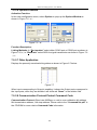
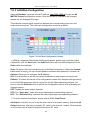
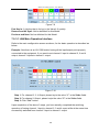
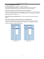
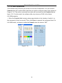
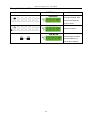
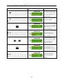
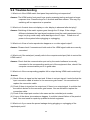
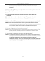
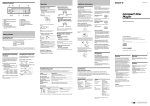
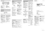
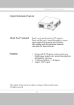
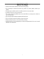
Matrix Switching System—User Manual Before You Begin Follow all instructions marked on the device during using. Do not attempt to maintain the device by yourself, any faults, please contact your vendor. Provide proper ventilation and air circulation and do not use near water. It is better to keep it in a dry environment. The system should be installed indoor only. Install either on a sturdy rack or desk in a well-ventilated place. Only using the power Adaptor supported with the device. Do not use liquid or aerosol cleaners to clean the device. Always unplug the power to the device before cleaning. Unplug the power cord during lightning or after a prolonged period of non-use to avoid damage to the equipment. 1 Matrix Switching System—User Manual Table of Contents 1.0 Matrix System Overview ..........................................................................................................4 1.0.1 Introduction ....................................................................................................................4 1.0.2 Packing ...........................................................................................................................5 2.0 Features .....................................................................................................................................6 3.0 Specifications ............................................................................................................................6 4.0 Host Installation ........................................................................................................................7 5.0 Front/Rear Panels ......................................................................................................................7 5.0.1 Front Panel .....................................................................................................................7 5.0.2 Rear Panel ......................................................................................................................9 6.0 HDMI Matrix and Peripherals Connection ............................................................................. 11 6.0.1 Input/Output Connections ............................................................................................12 6.0.2 HDMI Matrix / Control Computer Connection............................................................13 6.0.3 IR2 Connection ............................................................................................................16 6.0.4 Power connection .........................................................................................................16 7.0 Matrix Application Software...................................................................................................17 7.0.1 Software Introduction...................................................................................................17 7.0.1.1 Software Description.........................................................................................17 7.0.1.2 Software Activation...........................................................................................17 7.0.2 RS-232 Software Configuration...................................................................................18 7.0.2.1 RS-232 Main Operation Interface .....................................................................19 7.0.2.2 Disconnect Function Keys ................................................................................21 7.0.2.3 Select all output, DeSelect all output Switching Functions ..............................22 7.0.2.4 Disconnect all Command ..................................................................................23 7.0.2.5 RS-232 Memory Function.................................................................................23 7.0.2.6 Options Function ...............................................................................................24 7.0.2.7 Other Application ..............................................................................................24 7.0.2.8 Communication Protocol/Control Command Code ..........................................24 7.0.3 LAN Web Configuration ..............................................................................................25 7.0.3.1 LAN Main Operation Interface .........................................................................26 7.0.3.2 LAN Memory Function.....................................................................................27 7.0.3.3 LAN IP Function ...............................................................................................28 7.0.3.4 Other Application ..............................................................................................29 8.0 Operation Examples ................................................................................................................30 9.0 Troubleshooting.......................................................................................................................33 2 Matrix Switching System—User Manual 3 Matrix Switching System—User Manual 1.0 Matrix System Overview 1.0.1 Introduction Matrix Switcher is high performance HDMI switching equipment combining with video and audio. It is used for input/output cross switching of image signals. Through 8 separated HDMI sources, you can also transmit images input separately to each mulit-output equipments, thereby minimizing signal attenuation and ensuring high definition, integrating high fidelity graphics and audio signal output. Besides Matrix switcher is unlike typical HDMI switchers only communication limited the distance, through the HDMI-EP devices, you can over long distances to transmit signals. Maxtrix Switcher is used mainly in TV broadcasting projects, multi-media conference halls, and large display projects, TV teaching and command control centers. It boasts features of power interruption protection during power surge, LCD display and synchronous and integrate audio/visual switching functions. Supports 8 HDMI Type A or RJ-45 for input and output connectors. Beside it also supports a RS-232 or LAN communication port enables convenient communication with remote control equipment to switch the image signals. Figure 1-1 Matrix Switcher 4 Matrix Switching System—User Manual 1.0.2 Packing HDMI Matrix Host RS-232 Communication Connecting Cable Power Cord IR BOX LAN Line Controller 2 pcs of AAA battery HDMI Matrix Software CD User Manual 2 Rack-Mount Bracket 6 Screws (for Brackets) 5 Matrix Switching System—User Manual 2.0 Features HDMI 1.3a Compatible HDCP Compliant Supports RS-232 / Ethernet control Supports IR control Internal universal power supply 1U rack Available in 4x4, 4x8, 8x4, and 8x8 fixed I/O interfaces. Built-in Daughter Card (Board) Interfaces (LAN card optional) Mixed use either HDMI or Cat.X cables for inport and outport connection. Supports computer video up to 1920*1200 Supports HDTV up to 1080p EDID management (Copy from OUT port 1) 3.0 Specifications Input Connector 8 x HDMI Type A or RJ-45 Output Connector 8 x HDMI Type A or RJ-45 RS-232 Connector DB9 Female LAN Connector RJ-45 Select Switch 21 LCD Module 1 Max. Resolution 1080P Highest TMDS Frequency 225 MHz HDMI Cable Distance 10 meter (Max.) Cat.X Cable Distance 60 meter (Max.) Power 100~240VAC, 50~60Hz, internal Housing Metal Weight 2350 g Dimensions (LxWxH) 440x336x43mm 6 Matrix Switching System—User Manual 4.0 Host Installation The HDMI Series Matrix Host has a black metallic housing. It can be placed on a sturdy desk directly or installed on a 19-in bracket. 5.0 Front/Rear Panels 5.0.1 Front Panel Figure 5-1 Front Panel The Matrix Switching System suppor ts up to 8 Output/Input switching keys on the Front Panel allow you to switch singal quickly. There are four kinds of module combinations as below: Operation method No. 1: “Output Channel"+“ Input Channel" Click the Output button then click the Input button to set the combinations. Operation method No. 2: “STO or RCL"+“ Output Channel" Click the STO or RCL button then click the Output button. Operation method No. 3: single operation This example for EDID button, you can click the EDID button directly. Operation method No. 4: “STO and RCL"+“ Input Channel" Click the STO and RCL button then click the Input button to set the combinations. OUT1~8 keys (output channel): Indicate the Channel 1~Channel 8 for HDMI singal output to peripheral display. You can also use these keys to adjust the status or access the settings IN1~8 keys (input channel): Indicate the Channel 1~Channel 8 for HDMI singal input. You can use these keys to switch to the connection of the connected signal source channels. 7 Matrix Switching System—User Manual IR1: Infrared receiver. All: This key allows you to set single input channel to all output channels. - Press the “All” key. - Select the one of the IN 1~8 keys. - The selected IN x key will deliver the singal to all output channels. - You can also press the “All” key and then the “OFF” key to disable all the displayed switching settings. OFF: Disable the entire output channels. Press the one of the OUT x keys that you want to disable the output channel, then press the OFF key. You can also press the “All” button and then the “OFF” button to disable all the displayed switching settings. STO: The “Store Key” saves all current input/output corresponding relations. - Press the “STO” key firstly. (Supports up to 8 sets of memories, you can select the memory location through OUT1~OUT8) - Arrang the Output and Input channel combinations (output channel key 1~8). The relation between the Output and Input settings will be saved in the memory permanently. RCL: The “Retriever Key” retrieves the saved input/output corresponding relations. - Press the “RCL” key firstly. - Then make a random to select one of output channel key 1~8. - The system will retrieve the saved input/output status and implement current staus switching. EDID: FIX (fix mode) and TV1 (access the first output channel) selection key. - FIX mode: The matrix will supply a set of fixed EDID values to support up to only 1080P high performance TV. - TV1 mode: The matrix will accecc the EDID values of high performance TV that connected to the first output channel, and copy the EDID value to all the input channels so that the DVD player can support to all the HDTV. LCD: LCD display shows current HDMI matrix status and operation status. Press both the STO and RCL buttons to enter the EQ mode that only takes effective under RJ-45 Input modules (MX-RJI1_EQ mode). For example as below, make the EQ value of input channel 2 from 1 to 2. Click the IN button 2 on the front panel again; the EQ value will become 2 until to the value 8, then the value will return back to 1. Click again IN 8 Matrix Switching System—User Manual 5.0.2 Rear Panel Figure 5-2 Rear Panel The HX-2388 supports up to 8 input/output connectors (HDMI Type A or RJ-45) on the rear panel, each female terminals form the signal input/output connectors. The HX-2388 signal input/output terminal channels are numbered from right to left as OUT1~4 / IN1~8 / OUT5~8 channels. The input terminal channels supply you to connect to different equipment including DVD players and graphics workstations. The output terminals can be connected to projectors, video recorders, displays and multiplexes and so on. Power Port: The Power Port is applicable for 100~240VAC, 50~60Hz connected to the outlet of power source. Power Switch: To switch power ON or OFF the HDMI matrix host. RS-232: Use the RS-232 connection cabel to connect the computer serial port (COM1 or COM2) to the RS232 communication port of the HDMI matrix host. The computer can then be used to control the HDMI matrix after installation of application software. The RS-232 port is a 9-pin female connector. IR2: Connect to the IR BOX. Switcher: - - Pin1: Switch between RS-232 port and LAN port connection. Pin2: This Pin allows you to reset the IP value to 192.168.0.3. The steps are as below: a. Please adjust the pin2 down and re-start matrix. b. After the HX-2388 re-starts about 10sec, shut down your equipment. c. Adjust the pin2 up, then power on matrix again. d. The IP address will be restored to the default value: 192.168.0.3 Pin3: No definition. Pin # UP DOWN 1 LAN RS-232 2 NORMAL IP DEFAULT 3 NC NC 9 Matrix Switching System—User Manual LAN Port: Use the RJ-45 connection cable to connect the Internet and the HDMI matrix host. The entire PC at the same network can control the HDMI matrix host through the LAN port. IN1~8: Depend on the built-in modules, HDMI matrix host Input Channels are connected to the DVDs or HDMI-LP, for more information please refers to Appendix A. OUT1~8: Depend on the built-in modules, HDMI matrix host Output Channels are connected to the HDTVs or HDMI-RP, for more information please refers to Appendix A. When using the extender port modules, up port is for DDC function, down port is for VIDEO function. DDC function VIDEO function ) For RJ-45 Connector daughter board modules equipment, the connection has a collocation with HDMI-EP; please refer to the Appendix A for more information. Daughter board modules: MX-HDI1 HDMI Connector input MX-HDO1 HDMI Connector output MX-RJI1 RJ-45 Connector input (for extender port) MX-RJO1 RJ-45 Connector output (for extender port) HDMI Type A Connector pin definition: Pin # Signal Pin # Signal 1 TMDS Data2+ 11 TMDS Clock Shield 2 TMDS Data2 Shield 12 TMDS Clock- 3 TMDS Data2- 13 NC 4 TMDS Data1+ 14 NC 5 TMDS Data1 Shield 15 DDC-SCL 6 TMDS Data1- 16 DDC-SDA 7 TMDS Data0+ 17 DDC-Ground 8 TMDS Data0 Shield 18 +5V Power 9 TMDS Data0- 19 Hot Plug Detect 10 TMDS Clock+ 10 Matrix Switching System—User Manual 6.0 HDMI Matrix and Peripherals Connection Figure 6-1 HDMI Matrix System Connections ) Use the HDMI-EP devices to extend the connection, please refers to the Appendix A. 11 Matrix Switching System—User Manual 6.0.1 Input/Output Connections Use the HDMI connecting cable to connect the Input/Output serial port (No.1 ~ No.8) to the HDMI port of the DVD Player/HDTV or HDMI-EP. Figure 6-2 Input Connections Figure 6-3 Output Connections 12 Matrix Switching System—User Manual 6.0.2 HDMI Matrix / Control Computer Connection Use the RS-232 connecting cable to connect the computer serial port (COM1 or COM2) to the RS-232 communication port of the HDMI matrix host. The computer can then be used to control the HDMI matrix after installation of application software. Aside from using the front panel keys for switching operation, you are also permitted to use the RS-232 connection port for remote operation. Figure 6-4 (a) RS-232 and Control PC connection HX-2388 also supports a LAN port allows you to control the equipment host through PC Browser. Figure 6-4 (b) LAN port and Control PC Connection 13 Matrix Switching System—User Manual The RS-232 Leg functions are described as below: Pin No. Leg Description 1 N/u Null 2 Tx Send 3 Rx Receive 4 N/u Null 5 Gnd Ground 6 N/u Null 7 N/u Null 8 N/u Null 9 N/u Null Figure 6-5 Figure 6-5 (a) 14 Matrix Switching System—User Manual Figure 6-5 (b) ) The Matrix RS-232 port is defined as DCE. 15 Matrix Switching System—User Manual 6.0.3 IR2 Connection The HDMI matrix provides you an IR BOX for more convenient to react to the controller. Please connect the IR BOX to the IR2 port that is on the rear panel. Figure 6-6 IR Connection 6.0.4 Power connection Use the included power cord to connect from the power port on the rear panel of HDMI matrix host to the outlet. Figure 6-7 Power Connection 16 Matrix Switching System—User Manual 7.0 Matrix Application Software 7.0.1 Software Introduction The 《AV Matrix》 Matrix control software applies to different input/output matrixes. 7.0.1.1 Software Description The《AV Matrix》matrix testing software is an application tool developed for matrix testing and application. The software operation environment is as follows: Window98/2000/7/NT/XP/Vista/ operatng systems 32M interal memory or above 10M hard disk space or above CD-ROM At least one serial communication port 7.0.1.2 Software Activation First, you must power off both the HDMI matrix and the computer. Then, connect the matrix RS-232 port to the PC RS-232 port with the bundled communication cable. (Refer to the previous section “HDMI Matrix and Control Computer Connection”. Power on the HDMI matrix and the computer: Activate the AV Matrix.exe on the bundled CD-ROM in the control computer to enter the software configuration screen. 17 Matrix Switching System—User Manual 7.0.2 RS-232 Software Configuration The software controls signal connection between the corresponding input port and output port as required. The RS-232 main configuration screen is as below: Figure 7-1 RS-232 Software Configuration Screen ) HX-2388 is integrated Video/Audio switching equipment; please select the Video check box before you begin to operate the software. Scroll on the left area of the main screen to view contents as shown below. 18 Matrix Switching System—User Manual 7.0.2.1 RS-232 Main Operation Interface Refer to the main configuration screen as above, the marked blue area shows crossing matrix of output ports 01-08 and input ports 01-08. For the basic operation is described as below: Examples for Selecting Matrix Switching Functions: Example: Now there is an matrix having all the input/output ports properly connected to the equipment. If you want to set channel 1 input to channel 2, 3 and 4 output; channel 3 inputs to channel 1 output. There are 2 ways to implement the switching. Please follow the ways and steps to finish the switching functions: First way: Make sure you have selected “Video” check box ( the corresponding icons on the matrix to transform them into ). Directly click on to complete the switching operation. Second way: Step 1: Make sure you have selected “Video” check box ( ). Step 2: First select the “Output”number keys 02, 03 and 04 to the right of the blue configuration area, and select the “Input” number key 01 to the bottom. Then, press consecutively the previously selected “Output” number keys 02, 03 and 04 (or you can press the “Deselect all output” key). This way, you have selected “Input” 01 and “Output” 02, 03 and 04 switching. Step 3: First select the “Output” number key 01 to the right of the blue configuration area, and select the “Input” number key 03 to the bottom. Then, press the previously selected “Output” number key 01 (or you can press the “Deselect all output” key). This way, you have selected Input 03 and Output 01 switching. Upon completion of the above 3 steps, you have actually completed the switching operation of having channel 1 input to channel 2, 3 and 4 ouput while at the same time successfully switched from channel 3 input to channel 1 output. The main configuration screen also shows you some function buttons to easy operation: Disconnect: To disable the connections. After you had configured the connection between input and output ports, you can click this button to disable the connections. Select all output: Click this button to select all output ports including output 01~08. Deselect all output: Click this button to cancel presently selected output ports. After you had configured a connected combination, please click this button firstly for next settings. Disconnect all: To stop all the connections. Scan: To search the host controlled by the RS-232 Software Configuration. When the host name located on the left of the main configuration screen is empty, you can click the 19 Matrix Switching System—User Manual Scan to research and update the host Name and ID. Options: Allows you to configure the Port number and Baud rate. Exit: Click this button to exit the configuration screen. Save: Click this button to save the connected combinations both output ports and input ports. Load: Click this button to retrieve the previously saved settings. For more information and operations, please refer to next chapters. 20 Matrix Switching System—User Manual 7.0.2.2 Disconnect Function Keys Disable all the unused output ports. A specific example of operation is described as below: The present input and output relations are shown in Figure 7-2 below: Figure 7-2 First you have to disable the output ports including port 03、02、and 01. Step 1: First press down the output number keys 03, 02 and 01 to the right of the blue configuration area. Step 2: Press the “Disconnect” key; Step 3: Press the previously pressed output number keys 03, 02 and 01 (or press the “Deselect all output” key) to complete the operation. 21 Matrix Switching System—User Manual The final results will be as shown in Figure 7-3 below: Figure 7-3 7.0.2.3 Select all output, DeSelect all output Switching Functions (1)Select all output Function Description: You can use this function to select one all output ports for output to one input port. A specific example of operation is described below: Example: Now, you have an HX-2388 matrix with all input and output ports properly connected to the equipments. The needed input/output ports should be set to channel 1 input to all output-ports to output. ). Then, press the “Select Make sure you have selected the “Video” check box ( all output” key and select the input number key 01. Click on the matrix icons along the 01 row to transform them into to complete the command operation. (2)DeSelect all output Function Description: It is used to disable the Select all output function. 22 Matrix Switching System—User Manual 7.0.2.4 Disconnect all Command Function Description: To disable all the switching functions. Press the “Disconnect all” key to disable all the connections of input and output ports. 7.0.2.5 RS-232 Memory Function Function Description: To store and retrieve the settings. Store Functin Description: The Store Function saves all the present input/output switching relations to any Locations from #1 to #8 you desired. A specific example of the Store Function is described below: Store all the present input/output switching relations to Location #1. First, select Location #1, as shown in the figure below. Then click the Save key to save all the present input/output switching relations to Location #1. Figure 7-4 Retrieve Function Description: To retrieve the saved input/output switching relations. A specific example of the Retrieve Function is described below: To retrieve the input/output corresponding relations saved in Location #1. First, select Location #1 as shown in the figure below. Then click the Load key to retrieve all the Input / output corresponding relations stored in Location #1. , Figure 7-5 23 Matrix Switching System—User Manual 7.0.2.6 Options Function Activation Function: In the main configuration menu, select Options to prop up the Options Window as shown in Figure 7-6(a) Figure 7-6(a) Figure 7-6(b) Function Description: Linking Methods: In “Port number” select either COM1 port or COM2 port as shown in Figure 7-6(b); in “Baud rate” select 9600 for signal transmission as shown in Figure 7-6 (a) 7.0.2.7 Other Application Displays the presently saved switching status as shown in Figure 6-7 below: Figure 7-7 When input corresponding to Output is enabling, it shows the Output ports correspond to the Input ports; when they are disable it will show red “None” in the relative field. 7.0.2.8 Communication Protocol/Control Command Code Communication Protocol: Baud rate 9600bps, no odd or even calibration bit address, 8bit transmission address, 1bit stop address. Please refer to the “Command list.pdf” in the CD-ROM for more relative Command Code information. 24 Matrix Switching System—User Manual 7.0.3 LAN Web Configuration Open the Browser, keyin the default IP address: http://192.168.0.3 to login the AV MATRIX Control configuration screen. Once the default IP address is be changed, please use the changed IP to login. The software controls signal connection between the corresponding input port and output port as required. The LAN main configuration screen is as below: Figure 7-8 LAN Web Configuration Screen ) HDMI is integrated Video/Audio switching equipment, please only keyin the Output Channel No. into the Video field, the Audio field value will be a default depends on the Video value automatically. Scan: To search the host controlled by the LAN Web Configuration. When the Console List content is empty, you can click the Scan to research and update the Console List. Options: Allows you to configure the IP address. Set: Click this button to set the connected combinations both output and input ports. Refresh: To refresh the values of the configuration screen. Any changed settings directly on the HX-2388 equipment will not respond to the AV Matrix operating interface, you have to click the Refresh button to refresh the configuration screen so that showing the changed values. OFF: Disable the entire output channels. STO: The “Store Key” saves all current input/output corresponding relations. RCL: The “Retriever Key” retrieves the saved input/output corresponding relations. ) For more relatived information, please refer to 5.0.1. Front Panel. All Output: A Hot Key for you to set the same value to all output channel. Select the All Output check box, then key in example “5” value in the channel 1 output. Click anywere on the screen, the all channel output will become “5” value. 25 Matrix Switching System—User Manual Figure 7-9 Port Key In: A Hot key that is for key in the Value1~8 quickly. Reserve and AV Sync: Not be definited for this Model. Previous and Next: Not be definited for this Model 7.0.3.1 LAN Main Operation Interface Refer to the main configuration screen as above, for the basic operation is described as below: Example: Now there is an HX-2388 matrix having all the input/output ports properly connected to the equipment. If you want to set channel 1 input to channel 2, 3 and 4 output; channel 3 inputs to channel 1 output. Figure 7-10 Step 1: For channel 2, 3, 4 Output, please keyin the value “1” in the Video fields. Step 2: For channel 1 Output, please keyin the value “3” in the Video fields. Step 3: Click “Set” button. Upon completion of the above 3 steps, you have actually completed the switching operation of having channel 1 input to channel 2, 3 and 4 ouput while at the same time successfully switched from channel 3 input to channel 1 output. 26 Matrix Switching System—User Manual 7.0.3.2 LAN Memory Function Function Description: To store and retrieve the settings. Store Functin Description (STO): The Store Function saves all the present input/output switching relations to any Locations from #1 to #8 you desired. A specific example of the Store Function is described below: Store the present input/output switching relations to Location #2. First, select Location #2, as shown in the figure below. Then click the STO button to save the present input/output switching relations to Location #2. Retrieve Function Description (RCL): To retrieve the saved input/output switching relations. A specific example of the Retrieve Function is described below: To retrieve the input/output corresponding relations saved in Location #1. Select the Location #1 as shown in the figure below. The input/output corresponding relations stored in Location #1 will be showed directly. Figure 7-11 Figure 7-12 27 Matrix Switching System—User Manual 7.0.3.3 LAN IP Function Activation Function: In the main configuration menu, select Options button to prop up the Windows Internet Explorer dialog box, click “OK” to show the IP configuration screen as shown in Figure 7-11 Figure 7-13 In the Network Settings configuration, you can set the IP information by yourself (Fix IP) or click the Enable DHCP check box to get the IP from the DHCP (Float IP). ) Click the Default button to restore to default IP address. After changing the IP, you have to restart (power off then power on) the Host to make the changed values take effectively. ) You can also use the blue Switcher on the rear panel of the Host to reset the ignored IP. 28 Matrix Switching System—User Manual 7.0.3.4 Other Application The software utility will show you at least 32 unit host ID and Name. You can click the Console down list to select which Host that you want to configure output /input values as Fiugure 7-14. The entire connected Host name will be showed on the Console List as figure 7-15. For this model, the software utility only shows an ID:00 for the Name: HX-2388 presently. ) When the Console List is empty, please pay attention to the location of switch 1 on the rear panel of Host is correctly. Then, click Scan to research the configured Host. For HX-2388 model, only have to make the Console down list value to “00”. Figure 7-14 Figure 7-15 29 Matrix Switching System—User Manual 8.0 Operation Examples Example 1: Switch the NO.1 input signal to the NO.2 output channel. Key LCD Display Operation 1. Press the NO.2 key of the output channel, then the input channels will begin to flicker. 2. Press the NO.1 key of the Input channel. Example 2: Switch the NO.1 and NO.2 input signals to each NO.1 and NO.2 output channels. Key LCD Display Operation 1. Press the NO.1 key of the output channel, then the input channels will begin to flicker. 2. Press the NO.1 key of the Input channel. 3. Press the NO.2 key of the output channe, then the input channels will begin to flicker. 4. Press the NO.2 key of the Input channel. 30 Matrix Switching System—User Manual Example 3: Delete “All” settings. Key LCD Display Operation 1. Press the NO.2 key of the output channel, then the input channels will begin to flicker. 2. Press the NO.1 key of the Input channel. 3. Press the ALL key on the front panel, and then press the OFF key to cancel all the settings. 31 Matrix Switching System—User Manual Example 4: “STO” and “RCL” functions. Key LCD Display Operation 1. Press the NO.2 key of the output channel, then the input channels will begin to flicker. 2. Press the NO.1 key of the Input channel. 3. Press the STO key on the front panel. The Store Memory begins to flicker about 8 seconds. 4. Press the NO.1 key of the output channel to save the setting in the NO.1 channcel. 5. Press the ALL key on the front panel, and then press the OFF key to cancel the setting. 6. Press the RCL key on the front panel, The Recall Memory begins to flicker about 8 seconds. 7. Press the NO.1 key of the output channel to Load the previously saving. 32 Matrix Switching System—User Manual 9.0 Troubleshooting 1. What to do if the HDMI matrix front panel keys switching not responsive? Answer: The HDMI matrix front panel keys employ scanning testing and require longer response time. Press the keys for 2 seconds and then release. This way, key switching will be responsive in operation. 2. What to do if matrix does not display or color display is abnormal after hot plug? Answer: Switching of the matrix system goes through the IC chips. If the voltage difference between the input signal equipment and the matrix equipment is too large, hot plug could easily cause damage to the IC chips. Please turn off power to the system before plugging or unplugging. 3. What to do if loss of color reproduction happens or no video signal output? Answer: Please check if connectors at both ends of the HDMI signal cable are correctly connected. 4. What to do if the serial port (usually refer to the computer serial port) fails to control the HDMI matrix? Answer: Check that the communication port set by the control software is correctly connected to the corresponding serial port of the equipment. Also, check if the computer communication port is in good order. 5. What to do if the corresponding graphics fail to output during HDMI matrix switching? Answer: (1) Check if there is signal on the input end. If there is no input signal, it could be that the input connection cable is broken or the connector gets loosen. You are advised to replace the connection cable. (2) Check if there is signal on the output end. If there is no output signal, it could be that the cable is broken or the connector gets loosen. You are advised to replace the connection cable. (3) Check if the output port number is the same as the controlled port number. (4) If none of the above circumstances happen, it could be internal failure of the product itself. You must send for repair by qualified technical engineers. 6. What to do if you sense the power leakage during plugging or unplugging of the input/output ports? 33 Matrix Switching System—User Manual Answer: It could be that the equipment power is not properly grounded. You must properly ground your equipment; otherwise product life can easily be shortened. 7. What to do if the LCD displays normally and the communication port has return code but no image output? Answer: (1) It could be that the output/input connectors got loosen. Simply replace the connectors. (2) It could be the connection cable short-circuited. Simply replace the cable. (3) It could be the connection cable is broken. Simply replace the cable. 8. What to do if the HDMI matrix panel keys and communication ports are out of order? Answer: Check if the equipment power input is in good contact and the computer communication ports are in good order. If yes, it could be some internal failure of the product, please send for repair by qualified technical engineer. 9. What to do if operation and function failure occurred? Answer: Check if the equipment and the matrix system are in proper connection. If the problem persists, send the product to the maintenance center for repair. 10. How to avoid the equipment failure due to the high temperature? Answer: The equipment supports hot reaction function, when the inner temperature is over high, the equipment will shot down most of power automatically to avoid the damage happening until the temperature becomes suitable and implements continuity. This is only a preventive way to avoid the damage that comes from the bad fan and high temperature. The hot reaction fucnion will not be enabled in normal situation. 34