1
CC1101
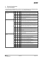
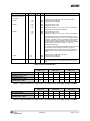
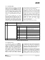
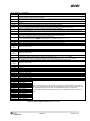
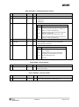
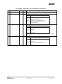
GDOx_CFG[5:0]
Description
Associated
to the RX FIFO: Asserts when RX FIFO is filled at or above the RX FIFO threshold. De-asserts when RX FIFO
0 (0x00)
is drained below the same threshold.
Associated to the RX FIFO: Asserts when RX FIFO is filled at or above the RX FIFO threshold or the end of packet is
1 (0x01)
reached. De-asserts when the RX FIFO is empty.
Associated to the TX FIFO: Asserts when the TX FIFO is filled at or above the TX FIFO threshold. De-asserts when the TX
2 (0x02)
FIFO is below the same threshold.
Associated to the TX FIFO: Asserts when TX FIFO is full. De-asserts when the TX FIFO is drained below the TX FIFO
3 (0x03)
threshold.
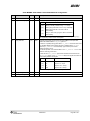
4 (0x04)
Asserts when the RX FIFO has overflowed. De-asserts when the FIFO has been flushed.
5 (0x05)
Asserts when the TX FIFO has underflowed. De-asserts when the FIFO is flushed.
Asserts when sync word has been sent / received, and de-asserts at the end of the packet. In RX, the pin will also de6 (0x06)
assert when a packet is discarded due to address or maximum length filtering or when the radio enters
RXFIFO_OVERFLOW state. In TX the pin will de-assert if the TX FIFO underflows.
7 (0x07)
Asserts when a packet has been received with CRC OK. De-asserts when the first byte is read from the RX FIFO.
Preamble Quality Reached. Asserts when the PQI is above the programmed PQT value. De-asserted when the chip re8 (0x08)
enters RX state (MARCSTATE=0x0D) or the PQI gets below the programmed PQT value.
9 (0x09)
Clear channel assessment. High when RSSI level is below threshold (dependent on the current CCA_MODE setting).
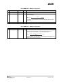
Lock detector output. The PLL is in lock if the lock detector output has a positive transition or is constantly logic high. To
10 (0x0A)
check for PLL lock the lock detector output should be used as an interrupt for the MCU.
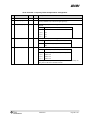
Serial Clock. Synchronous to the data in synchronous serial mode.
11 (0x0B)
In RX mode, data is set up on the falling edge by CC1101 when GDOx_INV=0.
In TX mode, data is sampled by CC1101 on the rising edge of the serial clock when GDOx_INV=0.
12 (0x0C)
Serial Synchronous Data Output. Used for synchronous serial mode.
13 (0x0D)
Serial Data Output. Used for asynchronous serial mode.
14 (0x0E)
Carrier sense. High if RSSI level is above threshold. Cleared when entering IDLE mode.
15 (0x0F)
CRC_OK. The last CRC comparison matched. Cleared when entering/restarting RX mode.
16 (0x10)
to
Reserved – used for test
21 (0x15)
22 (0x16)
RX_HARD_DATA[1]. Can be used together with RX_SYMBOL_TICK for alternative serial RX output.
23 (0x17)
RX_HARD_DATA[0]. Can be used together with RX_SYMBOL_TICK for alternative serial RX output.
24 (0x18)
to
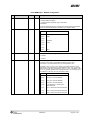
Reserved – used for test
26 (0x1A)
PA_PD. Note: PA_PD will have the same signal level in SLEEP and TX states. To control an external PA or RX/TX switch
27 (0x1B)
in applications where the SLEEP state is used it is recommended to use GDOx_CFGx=0x2F instead.
LNA_PD. Note: LNA_PD will have the same signal level in SLEEP and RX states. To control an external LNA or RX/TX
28 (0x1C)
switch in applications where the SLEEP state is used it is recommended to use GDOx_CFGx=0x2F instead.
29 (0x1D)
RX_SYMBOL_TICK. Can be used together with RX_HARD_DATA for alternative serial RX output.
30 (0x1E)
Reserved – used for test
to
35 (0x23)
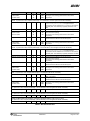
36 (0x24)
WOR_EVNT0
37 (0x25)
WOR_EVNT1
38 (0x26)
CLK_256
39 (0x27)
CLK_32k
40 (0x28)
Reserved – used for test
41 (0x29)
CHIP_RDYn
42 (0x2A)
Reserved – used for test
43 (0x2B)
XOSC_STABLE
44 (0x2C)
Reserved – used for test
45 (0x2D)
Reserved – used for test
46 (0x2E)
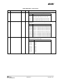
High impedance (3-state)
47 (0x2F)
HW to 0 (HW1 achieved by setting GDOx_INV=1). Can be used to control an external LNA/PA or RX/TX switch.
48 (0x30)
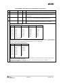
CLK_XOSC/1
49 (0x31)
CLK_XOSC/1.5
50 (0x32)
CLK_XOSC/2
51 (0x33)
CLK_XOSC/3
52 (0x34)
CLK_XOSC/4
Note: There are 3 GDO pins, but only one CLK_XOSC/n can be selected as an output at any
53 (0x35)
CLK_XOSC/6
time. If CLK_XOSC/n is to be monitored on one of the GDO pins, the other two GDO pins must
54 (0x36)
CLK_XOSC/8
be configured to values less than 0x30. The GDO0 default value is CLK_XOSC/192.
55 (0x37)
CLK_XOSC/12
56 (0x38)
CLK_XOSC/16
To optimize RF performance, these signals should not be used while the radio is in RX or TX
57 (0x39)
CLK_XOSC/24
mode.
58 (0x3A)
CLK_XOSC/32
59 (0x3B)
CLK_XOSC/48
60 (0x3C)
CLK_XOSC/64
61 (0x3D)
CLK_XOSC/96
62 (0x3E)
CLK_XOSC/128
63 (0x3F)
CLK_XOSC/192
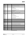
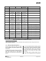
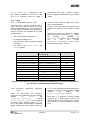
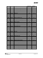
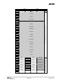
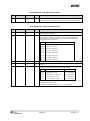
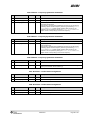
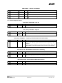
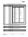
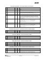
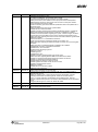
Table 41: GDOx Signal Selection (x = 0, 1, or 2)
SWRS061I
Page 62 of 98

































![Hacking Medical Devices - [media.blackhat.com]](http://vs1.manualzilla.com/store/data/005931227_1-f7547ce2b3ff0825b843d9b1dbb48800-150x150.png)