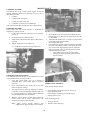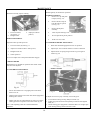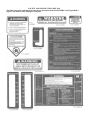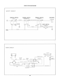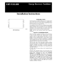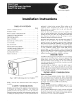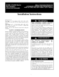
1
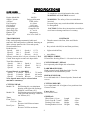
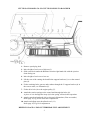
Rancher Ride-On
Owners Manual
Model No. 1766
•
•
•
•
WARNING
A mower is a high speed cutting tool. Safety precautions must be observed to reduce the risk of accident.
Careless or improper use may cause serious injury.
Be sure that you read and fully understand the contents of this Owner’s Manual. Should any point me unclear,
contact Rover-Scott Bonnar Limited, in your state or an authorized Rover-Scott Bonnar Service Agent for
assistance.
Keep the owners manual in a safe place for future reference. Read the Owners Manual periodically to, ensure
the continued safe and proper use of the mower.
SAFETY INSTRUCTIONS
• A mower user must be in good physical condition and
mental health and not under the influence of any drug or
alcohol which might impair vision or judgment.
• Do not use a mower when tired or fatigued. Lack of
alertness may cause serious injury.
• Know your controls.
Read and understand Owner’s manual before operating
mower. Learn how to stop the mower in an emergency.
Refer Operator’s Instructions.
• Do not lend or sell the mower without the Owner’s Manual.
• Be sure that anyone using the mower reads and fully
understands the information contained in this Manual and
knows how to safely operate the mower.
• Do not allow children or people unfamiliar with these
instructions to use the mower.
• Never mow whilst bystanders or pets are present in the
mowing area.
• Never carry passengers.
• Never mow while barefoot or wearing open sandals or
thongs. Wear long trousers and heavy non-slip shoes.
• It is advisable to wear suitable eye protection when
operating a mower.
• Before using, always visually inspect to see that the
blades, blade bolts, and cutter assembly are not worn or
damaged. Replace worn or damaged blades and bolts in
sets to preserve balance.
• Damaged blades and worn bolts are major hazards.
• Replace worn or faulty silencers.
• Always mount and dismount mower from left-hand side
(opposite side to discharge chute).
• Make sure the area to be mowed is clear of sticks, stones,
bones, wire and debris. They could be thrown by the blades.
• Store fuel in a cool place in a container specifically
designed for that purpose. In general, plastic containers are
unsuitable. Handle fuel carefully. It is highly flammable.
• Refuel outdoors only. Do not smoke when refueling
engine. Add fuel before starting engine. Never remove the
cap from the fuel tank or add petrol while the engine is
running. Allow engine to cool for several minutes before
refueling if engine is hot. If petrol is spilled, do not attempt
to start the engine, but move the mower away from the area
of the spill and avoid creating any source of ignition until the
petrol vapors have dissipated.
• Remove the fuel cap slowly to relieve fuel tank pressure.
• Check for fuel leaks while refueling or using the mower. If
a fuel leak is found, do not start or run the engine until the
leak is fixed and spilled fuel is wiped away.
• Take care not to get fuel on your clothing. If this occurs,
change your clothing immediately.
• Do not operate mower in confined space where exhaust
fumes (carbon monoxide) can collect.
• Mow only in good daylight.
• Start the engine carefully with feet well away from the
blades.
• When starting do not wrap the started rope around your
hand. Do not allow the started cord to snap back. Return the
started grip slowly to allow the cord to rewind properly.
• Strictly follow the operator instructions before attempting
to start the machine.
• Never mow where the machine could tip or slip.
• If machine stalls going uphill, stop blades and back slowly
down.
• Mow up and down slopes. Never mow across a slope.
Exercise extreme caution when changing direction on slopes.
Do not mow excessively steep slopes.
• Do not accelerate or stop the mower suddenly when on a
slope.
• Be extremely careful when using a mower on slopes. Stay
alert for holes in the terrain and other hidden hazards.
• Disengage cutter drive before mowing across gravel
drives, walks or roads.
• Do not mow in reverse. When reversing keep a careful and
continuous observation of the entire area behind the mower.
• Never use the mower unless all guards provided by RoverScott Bonnar Limited are in position.
• Never disconnect the safety switches and never operate
the mower if any safety switch is inoperative.
• Never over-speed the engine or alter the governor settings.
Excessive speed is dangerous and shortens mower life.
• Take all precautions when leaving the mower unattended.
Disengage the cutter drive, set the park brake, shift into
neutral, stop the engine, and remove the key.
• Stop the engine and remove the key whenever you leave
the mower, even for a moment.
• Stop the engine and disconnect the spark plug lead and
inspect mower if:
a) The mower begins to vibrate abnormally: or
b) After striking a foreign object.
Repair the damage before continuing further operation of
the mower.
• Stop the engine and disconnect the spark plug lead before
clearing blockages, checking or working on the mower.
• Never pick up or carry a mower while it is operating.
• Where fitted, turn fuel tap off at the conclusion of mowing.
• When transporting in a vehicle, secure the mower to
prevent movement, roll-over, fuel spillage, and mower
damage.
• Keep all nuts, bolts and screws tight to be sure the
equipment is in safe working condition.
• Never modify the mower in any way. Use only replacement
parts made and guaranteed by Rover-Scott Bonnar Limited.
• Keep all safety devices (guards and switches) in place and
working.
• Keep the engine free of grass, leaves or excessive grease –
these can be a fire hazard.
• Store the mower in a well ventilated room away from
naked flames such ad may be found in hot water heaters.
SAFETY FEATURES
⎯ Traction drive, blade drive and seat safety
interlock:
⎯ Enclosed engine and muffler:
⎯ Enclosed drives:
⎯ Full foot rest:
⎯ Low centre of gravity stable wide track.
⎯ Parking brake.
⎯ Convenient – easy to operate controls
1
SPECIFICATIONS
ROVER RANCHER
Machine Model No.
Engine Model No.
Single Cylinder
4 Stroke
Fuel Capacity
Oil Capacity
Lubrication
Spark plug type
Spark Plug Gap
Ignition Type
Engine Oil
1766
To emphasize special information the words
WARNING and CAUTION are used.
280702
Briggs & Stratton
12 HP. 465cc
4.0 Litres
1.42 Litres
Gear Impellor
Champion CJ8
0.7 to 0.8
Magnetron
10w-30 or SAE 30
TRANSMISSION
Fully enclosed and permanently lubricated
transaxle. Diff and gearbox combined featuring an
inline selector pattern with 5 Forward speeds,
Neutral and Reverse.
Reduction are –
Speed1
46.8:1
Speed 4
15.7:1
Speed 2
30.1:1
Speed5
13.3:1
Speed 3
20.1:1
Reverse
40.1:1
Primary traction drive is by an A Section, V Belt
Clutch from engine to trans-axle input shaft.
Total Drive Reduction
Speed1
104:1
Speed 2
66.6:1
Speed 3
44.5:1
Speed 4
Speed5
Reverse
34.8:1
29.5:1
88.8:
Ground Speed: At 3600 RPM
Speed1
2.5 km/hr Speed 4
7.5 km/hr
Speed 2
3.9 km/hr Speed5
8.8 km/hr
Speed 3
5.8 km/hr Reverse
2.9 km/hr
Note: Speeds must only be selected when
machine is stationary.
CUTTING HEAD
Model 178:
Full floating die cast aluminum
housing with right side discharge.
Width of cut 965mm (38”)
Model 170:
Full floating pressed steel housing
with right side discharge. Width of
cut 760mm (30”).
Tyres
Front Tyres –
13 x5.00 Tube
Pressure 140 KPA maximum
Rear Tyres – Tubeless
Pressure 70 KPA maximum
WARNING: The safety of the user and others
involved.
Personal injury may result should this information
be disregarded.
CAUTION: Follow these instructions carefully to
avoid mower damage and loss of warranty.
∗
CONTROLS
Throttle control with Fast, Slow and Choke
positions;
∗
Key switch with Off, On and Start positions;
∗
Light switch Off/On;
∗ Amp Meter.
STEERING WHEEL
325mm Dia. Steering Wheel. 1-1/4 turns lock to lock.
CLUTCH BRAKE / PEDAL
Foot operated pedal. Right side of machine.
PARK BRAKE KNOB:
Hand operated catch. Right hand side. Used in
conjunction with clutch/brake pedal.
SPEED SELECTOR:
Lever left hand side. 5 Forward speeds, Neutral and
reverse.
CUTTING HEIGHT:
Lever right hand side. 8 heights of cut positions from
15mm to 65mm.
Cutter drive:
Lever in rear cowl.
GENERAL:
Wheel Base, 111cm
Track 63cm R: 71cm F.
Turning Circle 4.0m
Turning Radius 85.0cm
2
Length
Width
Height
Weight
156cm
83cm
95cm
180kg
FITTING OF MODEL 170-178 CUTTING DECKS TO RANCHER
1. Remove spark plug lead.
2. Move height of cut lever to high cut (3)
3. Slide cutter deck under the Rancher from the right hand side with the ejection
chute facing out.
4. Move height of cut lever to low cut.
5. Lift the rear of the cutting deck and fit the support brackets (1) over the control
pins (2).
6. Fit the retaining bolts, spacers and washers through the U support bracket (4) in
the correct order, see illustration (5).
7. Fit the drive belt (^0 to the engine pulley (7).
8. Attach the tension springs to the cutter head through the holes (8).
A piece of wire through the loops (9) in the spring will assist this operation.
9. Attach cutter head pushrods (10) as shown in illustration. (Pins on outside)
Refer page 10, fig 18 for cutter drive adjustment.
10. Attach and adjust cutter head brake rod. (11)
Refer page 10, Fig 19 for adjustment.
REFER TO PAGE 11 FOR CUTTERHEAD TILT ADJUSTMENT
3
LOOSE PARTS KIT
DESCRIPTION
Steering wheel
Roll Pin
Stone Guard Assembly
Spring – Stone Guard
‘E’ Clip
Ignition keys
Plug Spanner
QTY
1
1
1
1
1
2
1
USE
On steering shaft
Secure steering wheel to shaft
Fitted to cutter head
On stone guard pivot rod
In groove in pivot rod
To start machine
To remove spark plug
SETTING UP INSTRUCTIONS
Fig.2
Fig.4
5. Secure by clipping an ‘E’ Clip into the groove
on the pivot rod. See Fig.4.
INSTALL STEERING WHEEL
1. Slip steering wheel over steering shaft and
align the wheel hole with the shaft hole;
INSTALLING THE BATTERY
2. Insert drift punch – partially through the
BATTERY
holes to maintain alignment and insert roll
pin in the opposite side; See Fig.2.
3. Drive roll pin in until flush with the outside
of the wheel.
1. Remove battery as follows;
(a)
(b)
Remove terminal cable from battery
Undo wing nuts and remove clamp
bar.
2. The battery is not fitted with Electrolyte.
This should be done by adding 33% strength
battery acid to each cell until plates are
covered. Electrolyte must be purchased
from a local battery supply outlet.
IMPORTANT: DO NOT OVERFILL BATTERY. ACID
WILL OVERFLOW INTO OTHER PARTS OF THE
MACHINE AND SEVERE CORROSSION AND
DETERIORATION WILL RESULT.
Fig.3
FIT STONE GUARD
1. Slip spring onto stone guard pivot rod so
that the short leg rests on top on the stone
guard;
2. Now twist the spring as shown and fed the
end of the pivot rod into the forward pivot
bracket; See fig.3
3. Insert the short end of the pivot rod fully
into the rearward pivot bracket;
4. Release the spring. It should spring down
onto the top of the cutter head and be
tensioning the stone guard down;
3. Leave filler caps off and connect battery
charger to battery terminal. Charge at the
rate indicated in the instructions supplied
with the battery.
4. After charging, check that Electrolyte is still
covering plates, if not, add to correct level.
Install filler caps.
5. Replace battery and secure.
6. Install the positive (red) cable to the positive
(+) terminal and the negative9black) cable
to the negative (-) terminal.
4
BEFORE OPERATING
FILL CRANKCASE WITH OIL.
Do not mix oil with petrol. – Engine damage may result.
The rider mower may be delivered with out oil in the
crankcase. Oil must be added before attempting to start the
engine.
1.
2.
1. Place machine on level surface. Open the bonnet. Ensure
3.
4.
that the oil plug is securely tightened. Clean around
dipstick.
2. Unscrew and remove dipstick from oil filler tube.
3. Insert funnel into filler tube and slowly add oil in
accordance with the engine manufacturer’s direction.
Open bonnet and clean around fuel tank cap so foreign
matter cannot enter fuel tank when cap is removed.
Using a funnel, fill tank with regular grade or unleaded
petrol. Replace the cap.
Wipe up any petrol that may have spilled.
Close and secure bonnet.
CHECK TYRE PRESSURE.
Check and maintain tyre pressure at 140 KPA (20 PSI) front
and 70 KPA (10 PSI) rear maximum
Note: Avoid premature engine failure by ensuring the
funnel is clean so contaminants are not introduced
into the crankcase. Wipe any oil spills so it will not
cause dirt to collect on the engine
ADJUSTING THE SEAT
Tip the seat forward, loosen
the seat securing screws.
Relocate the seat for
operator comfort. Tighten
the seat securing screws and
lower the seat
4. Ensure oil level is at the full mark on the dipstick, when
screwed completely in. When finished replace dipstick
and retighten.
Note: See Maintenance Instructions
FILL FUEL TANK – See Safety Instructions.
Use only regular grade or unleaded petrol.
Fig 5
CONTROLS
Fig 6
1.
2.
3.
4.
5.
6.
Throttle control – Mounted on the dash panel and
connected to the engine carburetor controls. Has the
symbols for Slow, Fast and Choke.
Ignition Switch – This switch is part of the battery
ignition system and has three positions marked for Off,
On and Start. The switch is key operated and
automatically returns to the On position from Start
position when released.
Light Switch – On/Off toggle switch on dash panel for
actuating the headlights. Lights will not function when
engine is not running.
Amp Meter – Mounted in the dash panel it indicates the
battery charging current and discharge.
Brake/Clutch – Foot operated pedal on right side of
machine. Depressing the pedal disengages the drive belt
and engages Brake Disc .
7.
8.
9.
5
Parking Brake – Hand operated knob right hand side.
Depressing the brake clutch foot pedal enables this knob
to be engaged and disengaged. Brake is locked on with
knob in up position.
Speed Selector – Located on left of seat. In line selector
with speeds 1, 2, 3, 4 and 5 Down from Neutral and
Reverse through spring gate and up from Neutral.
Cutting Height Adjuster – Located on right of seat with
low cut at bottom and high cut at top of setting.
Cutter Drive – Lever located on left hand side of seat
mounting box. Down position disengages blade drive and
applies blade brake, Up position engages blades.
OPERATING INSTRUCTIONS
TO START THE ENGINE:
-
Move the throttle lever to the slow position;
Note the engine will not start unless the cutter drive is
disengaged, and clutch/brake pedal is depressed.
-
Turn the ignition key to Off. Remove the keys;
-
Depress clutch/brake pedal – Apply the park brake;
-
Move the speed selector to neutral;
-
Disengage the cutter drive;
-
Move the throttle lever to the choke position;
-
Turn the ignition key to the start position and release;
-
when the engine starts;
-
Move the throttle lever to about ¼ position.
IMPORTANT:
-
The parking brake should always be applied before
leaving the machine;
-
The parking brake must be released before attempting to
drive;
-
Depress the clutch/brake pedal when selecting or
changing speed;
-
Do not select speed while the machine is moving.
ENGAGING CLUTCHES:
-
TO MOW OR DRIVE:
When engaging the cutter drive lever or releasing the
clutch/brake pedal, always operate slowly. Do not use a
jerking motion. Moving these controls too fast could
possibly overload and stall the engine.
-
Depress clutch/brake pedal;
-
Disengage the parking brake;
-
Select height of cut;
-
Move throttle to about ¾ position;
-
Engage cutter drive;
REMEMBER:
-
Select desired speed;
-
Always look behind the machine before reversing;
-
Slowly release clutch/brake pedal to move off.
-
Do not refuel when the engine is running or while it is
hot;
TO STOP ENGINE:
-
Keep bystanders away – Keep hands and feet clear of
moving parts;
-
Depress clutch/brake pedal;
-
Keep the machine clear of grass and debris;
-
Move the speed selector to neutral;
-
Keep all guards in place;
-
Disengage the cutter;
-
Apply the parking brake;
CAUTION:
-
To avoid loss of control always come to a complete
stop before selecting speeds and slow down when
turning.
MAINTENANCE INSTRUCTIONS
Periodically check the machine and cutting mechanism. If
parts are worn or need replacing do so by using only Genuine
Rover Replacement Parts.
a). The air cleaner element not being serviced
regularly;
b). The air cleaner damaged or dislodged.
There is a comprehensive Rancher Spare Parts List contained
in this book to help you select the right part quickly.
2.
Before working o the mower, disconnect the spark plug lead
from the spark plug and place it where it cannot contact the
spark plug.
Dirt or abrasives entering the engine via the oil filler
tube due to –
a). Using a funnel not cleaned of dirt and grit,
b). Topping up with contaminated oil. Oil stored in
an unclean container.
CHECK YOUR Rover rancher frequently for loose nuts,
bolts, belts, etc., and keep these items correctly tightened and
adjusted.
3.
Lack of oil. It is important to –
a). Check the oil level regularly ( every 5 hours of
Note: A check after the first two hours operation is
recommended. Engine failure or rapid engine wear mainly
result from the following causes –
operation),
b). Maintain a full sump.
1.
Dirt or abrasives entering the engine via the air
cleaner due to –
6
MAINTENANCE INTERVAL CHART
See
5
25
page
Hours
Hours
Change oil (Initial)
Change oil (Periodic)
Check Interlock
7
7
11
x
Check Cutting Blades
Check Cutting Unit Brake
10
x
Check Rear Wheels Brake
Lubricate Pivot Points
10
8
x
x
Lubricate Throttle Cable
8
x
Grease Front Axle Spindles
Service Air Cleaner
8
7
x
x
Check Spark Plug
Check Drive Belts
7
-
x
x
Check Tyre Pressure
5
x
Clean Outside Of Engine
Clean Cutter Housing
-
x
x
Paint Chipped Surfaces
-
x
PERIODIC SERVICE EVERY 25 HOURS
50
75
100
125
150
175
200
x
x
x
x
x
AIR CLEANER: Dual Element Type –
1.
Remove two cover knobs and remove air cleaner cover.
2.
Remove foam pre-cleaner, if so equipped.
(a). Wash pre-cleaner in liquid detergent and warm water
to remove dirt.
(b). Wrap pre-cleaner in cloth and squeeze dry.
(c). Saturate foam in engine oil. Squeeze to remove
excess oil.
3.
Remove two nuts from top of cartridge.
4.
Remove cartridge and clean air cleaner body carefully to
prevent dirt from entering carburetor. Brush dirt from
lower air cleaner body into duct.
5.
Clean cartridge by gently tapping on flat surface.
Fig 8
Place an oil pan under oil drain channel in side
on chassis.
3. Remove oil drain plug and allow to drain
completely.
4. Refit oil drain plug and tighten. Refill sump
with new oil. For correct viscosity and service
classification see the engine manufactures
Instruction
2.
(a). If very dirty, replace cartridge or wash in low or non
sudsing detergent and warm water solution.
(b). Rinse out thoroughly from INSIDE OUT until water
is clear.
(c). Cartridge must be allowed to stand and air dry
thoroughly before using.
6.
SPARK PLUG:
Reassemble air cleaner.
Note: Nuts holding air cleaner cartridge must be installed
with fiber washers down on cartridge plate to prevent dirt
from entering carburetor. Tighten nuts by hand. Over
tightening could collapse cartridge.
The spark plug gap gradually increases during engine running
and should be checked periodically and whenever the engine
malfunctions.
1. Clean around spark plug area so that dirt will not enter
engine when plug is removed;
2. Disconnect spark plug lead and remove spark plug;
3. Check condition of electrodes and ensure there is no
damage to insulator;
4. Carefully clean the spark plug. Do not grit blast.
5. Set gap to .8mm (.030”)
6. Install in engine and tighten to 20Nm. If a torque wrench
is not available hand tighten plug. Then with tube spanner
tighten plug about 1/12 of 1 turn.
7. Refit high tension lead. Push onto plug firmly.
Note: Petroleum solvents, such as kerosene, are not to be
used to clean cartridge. They may cause deterioration of
the cartridge. DO NOT OIL CARTRIDGE. DO NOT USE
PRESSURIZED AIR TO CLEAN OR DRY THE
CARTRIDGE.
OIL CHANGE
See engine manufacturer’s instructions.
1.
Place engine on a level surface. Start and run engine for a
period to warm the oil;
7
MAINTENANCE
COOLING SYSTEM:
The Rancher has an air cooled 4 stroke engine. It must be
cleaned frequently. Remove any build up of grass, dirt or
other debris from the –
1. Cylinder;
2.
Cylinder head cooling fins;
3.
Cooling air intake screen and
4. Carburettor governor levers and linkages.
This will ensure adequate cooling and correct engine speed.
COOLING SYSTEM:
Proper choke and stop switch operation is dependant on
adjustment of remote controls –
1. Loosen outer cable under clamp screw (D) on engine;
See Fig. 9.
2.
Set throttle control to choke position;
3.
Adjust outer cable under clamp plate so that choke is
operated;
4.
Tighten clamp plate screw and check –
Fig. 10
5.
6.
7.
8.
(a). Choke does not operate in fast position, and
Stop switch operates correctly.
Move throttle to the slow position and adjust the slow
running stop screw (B) to give an engine speed of 1700
to 1800 RPM.
Adjust the idle needle valve (C) slowly in (lean) and out
(rich) until engine idles smoothly.
Reset engine idle speed.
Check operation. Engine should increase speed without
hesitation when throttle control is moved quickly from
slow to fast. If the engine tends to die out, adjust the
high speed needle valve 1/8 turn anti-clockwise until
engine accelerates smoothly.
⎯ Never tamper with engine governor setting.
⎯ Changing of engine governor speed will void
engine warranty.
Fig. 9
CARBURETTOR ADJUSTMENT:
The carburettor has been factory set and should only require
occasional fine tuning. See Figs 9 and 10.
1. Close high speed needle valve (A) in bottom of
carburettor bowl. Close finger tight in clockwise
direction;
Fig. 11
LUBRICATION GENERAL:
2.
Open (anti-clockwise) the needle valve two turns
(that is an approx. setting);
Using General Purpose Grease –
3.
Start engine and let it warm up. Approx two minutes.
Cutter drive must be disengaged. Speed selector must
be in neutral position, air cleaner must be fitted and
secured and fuel tank must be half full.
⎯
⎯
⎯
⎯
4.
With the engine running at high speed, adjust the
needle valve1/8 turn at a time. Clockwise or anticlockwise until engine runs smoothly.
Using Clean Engine Oil –
Note:
Grease nipples on front wheel pivots. See Fig.11
Front axle beam guides.
Grease nipples on steering pivot blocks Fig.21
Steering gears Fig. 21
⎯ Jockey pivot arms
⎯ Throttle control cable fig.9
Allow several seconds between each
adjustment for engine to adapt to new settings.
8
⎯ Cutter Drive Lever Pivot;
MAINTENANCE
WHEEL REMOVAL:
⎯ Clutch/brake pedal pivot; See Fig.15
⎯ Tie rod ball ends; See Fig. 11
⎯ All connecting rod pivot points.
Note: All ball bearings are sealed and require no maintenance.
TRANSAXLE:
Fig. 13
This transmission is fully enclosed and permanently lubricated.
No maintenance necessary.
Fig. 14
CAUTION:
CUTTING UNIT:
Always deflate tyre before removing rim
nuts on front wheel only.
Front –
1. Chock wheels and remove axle nut; See Fig. 13
Remove spark plug lead and disengage cutter drive before
working on cutter unit, to prevent accidental starting of the
machine.
Before using machine always inspect cutting unit to see that
then cutting disc, blades and blade fixings are not worn or
damaged.
Always check after striking a solid object. Do not operate
machine when unusual vibration occurs.
2.
Raise front of engine;
3.
Slide wheel from shaft;
4.
Replace in reverse order;
5.
Retighten axle nut firmly.
Replace worn or damaged blades in sets to preserve balance.
Rear1.
Remove any build-up of grass or clogging within the cutting
unit or discharge chute or safety flap.
2.
Remove four wheel nuts.
3.
Slide wheel from hub.
4.
Replace wheel nuts and tighten.
CUTTING UNIT REMOVAL:
Chock front and rear wheels of machine,
ADJUSTMENTS
CLUTCH ROD ADJUSTMENT
Fig. 12
1.
Remove drive belt. Run it off of front pulley.
2.
Remove tension springs. A loop has been provided on the
spring to assist in this operation; See Fig.12.
Fig. 15
3.
Disconnect cutter deck push rods and blade brake rod.
Required to take up transmission belt stretch.
4.
Undo and remove large retaining bolts (A).
1.
Remove (R) clip from pedal pivot. See Fig. 15.
5.
Slide the cutter head forward this will allow the rear to be
lowered to the ground.
2.
Slip rod to rear of machine.
6.
The cutter head can now be slid out from under the
machine.
3.
Adjust nut on rod so that it is 3mm clear of pivot block when
pedal is in a fully up position;
7.
Replace in reverse order.
4.
Check for operation.
9
MAINTENANCE
CUTTER HEAD BRAKE
BRAKE ROD ADJUSTMENT
Should regularly be checked for operation.
Should not normally require resetting.
PAD REPLACEMENT
1.
Remove ‘R’ clip and push
rod pin (See Fig. 19).
1.
3.
Fig. 17
Loosen lock nuts;
(A) See Fig. 17
Retighten nuts.
2. Adjust pivot block
position;
BRAKE ADJUSTMENT
Required to take up brake pad wear.
2.
Remove brake rod pivot
bolt (B) and two spacers
(see Fig. 19).
3.
Remove brake plate
assembly.
4.
Drill out pad retaining rivets.
5.
Rivet replacement pad in position.
6.
Refit in reverse order.
CUTTER HEAD BRAKE ADJUSTMENT
1.
Loosen lock nut; (B) See Fig. 17.
1.
With cutter head disengaged and in low cut position.
2.
Adjust nut a small amount to take up wear;
2.
Adjust nyloc nut on rod till clearance of 5mm is obtained.
3.
Retighten lock nut;
3.
Adjust tension on spring using lock nuts to give length of
52mm. Fig. 20.
4.
Check operation.
Do not over-adjust. Set so that park brake knob engages.
PARKING BRAKE
Should always be checked for operation after clutch / brake
rods have been adjusted.
SPRING GEARS
CUTTER DRIVE ADJUSTMENT
Fig 18
1.
Mover cutter head lever to engaged position and lower
deck to low cut.
Fig. 21
2.
Adjust length of push rods so that cutter head engagement
shaft lugs are vertical.
To adjust out excessive play caused by wear in the gears.
3.
Adjust nyloc nuts on engagement lever rod to give approx.
32mm gap between top of lever and end of slot. Fig. 18.
1.
2.
3.
Note:- After adjusting cutter drive check blade brake
adjustment.
10
Loosen bolts securing steering shaft pivot block (A).
Lightly tap pivot block towards layshaft pivot block and retighten
bolts (A).
Check steering gear engagement. Check that there are no tight spots
when turning steering wheel from lock to lock.
MAINTENANCE
STEERING RODS
Should not normally require resetting.
1.
Loosen rod lock nut; (a) See Fig. 11.
2.
Release the fixing bolt;
3.
Turn tie rod end to adjust for length clockwise to shorten,
anti-clockwise to lengthen;
4.
Replace the fixing bolt and tighten;
5.
Tighten rod lock nut;
6.
Make sure rod is free to pivot.
CUTTER HEAD TILT
This should not normally require resetting.
SAFETY INTERLOCK SYSTEM
The safety interlock system has been designed for your
protection and should not be tampered with. It gives the
Rancher the following characteristics.
The engine will not start unless the speed selector is in the
neutral position, the cutter drive is disengaged and the
clutch/brake pedal is depressed.
NOTE: The engine should stop if the operator leaves the seat
with the speed selector and/or the cutter drive
engaged.
WARNING: If the interlock system fails, see an
authorized dealer. Do not operate until the
fault is corrected
1.
Loosen U-Bracket nuts; (B) See Fig. 12.
CAUTION: Safety switch circuit may become defective if
wet. Do not spray switches and connections.
2.
Adjust nuts up or down to set tilt;
STORAGE
3.
Model 178 (965 mm cut) does not require tilt.
Model 170 (760 mm cut) does require back of blade
circle tilted 15mm above front of blade circle in low cut
position’
Never store engine with fuel in tank indoors or in poor
ventilated enclosures where fuel may accumulate.
4.
Retighten all nuts.
STEERING STOPS
This should not normally require resetting.
1. Check if steering segment gear rotates in both directions
and contacts peg on chassis. If segment gear contacts then
stops are correct. If not adjust as follows.
2. Loosen lock nut on front beam axle and adjust bolt till
contact is made between segment and peg. Check in both
directions.
3. Retighten lock nut.
HEIGHT OF CUT ADJUSTMENT
To adjust the height of
cut rotate the nyloc nut
(A) situated under the
centre of machine on the
rear cutter support
assembly.
Adjust nyloc nut to
obtain low cut at front of
blade circle of 15mm.
If machine is to be stores over 30 days proceed with the
following:1. Remove all fuel from carburettor and fuel tank to prevent
varnish-like gum deposits.
2. Remove spark plug and pour 30 ml of engine oil into
cylinder. Crank engine several times to distribute oil.
Replace spark plug.
3. Clean engine and cooling fins, etc., of any clippings, dirt
and chaff.
4. Clean underside of mower and cutting unit. Paint any
chips or scratches.
5. Lubricate chassis components.
6. Remove and charge battery and store in a cool dry spot.
Recharge every 30 days.
7. Store machine in a clean dry spot.
REMOVAL FROM STORAGE
1.
Change oil.
2.
Fill fuel tank with fuel.
3.
Check spark plug.
4.
Check drive belts.
5.
Check drive chain.
6.
Lubricate drive chain.
7.
Lubricate pivot points.
8.
Grease front axle spindles.
9.
Check tyre pressure.
10. Check safety interlock.
11. Check cutting blades.
11
NOTES
12
SAFETY AND INSTRUCTION DECALS
The following safety and instruction decals are mounted on the RANCHER Front Engine Rider.
Replace any that become damaged or illegible.
CIRCUIT DIAGRAMS
14
TROUBLE SHOOTING
PROBLEM
Engine loses power.
Engine over heats.
Mower vibrates abnormally.
Cutter does not rotate.
Mower does not drive.
Engine does not start, hard to
start, loses power, or fails to keep
running.
POSSIBLE CAUSES
1. Oil level in crank case is low.
2. Cooling fins and air passages under
engine blower housing are blocked.
3. Engine load is excessive.
4. Air cleaner is dirty.
5. Dirt or water is in fuel.
6. Carburettor is adjusted incorrectly.
7. Spark plug is pitted, fouled or defective
in some other way.
1. Cooling fins and air passages under
engine blower housing are blocked.
2. Carburettor is adjusted incorrectly.
3. Oil level in crank case is low.
4. Engine load is excessive.
1. Engine mounting bolts are loose.
2. Loose cutter pulley, idler pulley or drive
pulley.
3. Cutter assembly is unbalanced.
4. Cutter assembly is loose.
1. Cutter belt is worn, loose or broken.
2. Cutter drive belt is off pulley.
1. Drive belt is worn, loose or broken.
2. Drive belt is off pulley.
3. Unable to select speed on transaxle.
1. Fuel tank is empty.
2. Speed selector.
3. Cutter drive is engaged.
4. Spark plug is loose.
5. Spark plug lead is loose or disconnected
from spark plug.
6. Spark plug gap is incorrect.
7. Spark plug is pitted fouled or defective
in some other way.
8. Wrong spark plug is used.
9. Electrical connections are loose.
10.Carburettor is adjusted incorrectly.
11.Air cleaner is dirty.
12.Vent hole in fuel tank is plugged.
13.Dirt or water in furl system.
14.Dead battery.
15.Defective points, condenser, ignition
coil, or ignition switch.
16.Module or switch is defective.
1. Air cleaner is dirty.
2. Oil level in crank case is low.
3. Cooling fins and air passages under
engine blower housing are plugged.
4. Idle speed is too low or high speed
mixture is incorrect.
5. Dirt or water in fuel system.
}
Engine does not idle or idles
poorly.
6. Vent hole in fuel tank is plugged.
7. Spark plug is pitted fouled or defective
in some other way.
15
CORRECTIVE ACTION
1. Add oil to crankcase.
2. Remove obstruction from passage.
3. Select a lower speed to reduce load.
4. Clean air cleaner element.
5. Have machine serviced by an Authorized
Service Dealer.
6. Adjust the carburettor.
7. Install new correctly gapped spark plug.
1. Remove obstruction from cooling fins and air
passage.
2. Adjust the carburettor.
3. Add oil to crankcase.
4. Select a lower speed to reduce load.
1. Tighten mount bolts.
2. Tighten the appropriate pulley.
3. Replace broken blades in set.
4. Tighten securing nut.
1. Install new cutter drive belt.
2. Install cutter drive belt.
1. Install new drive belt.
2. Install drive belt.
3. Have machine serviced by an Authorized
Service Dealer.
1. Fill fuel tank with petrol.
2. Select neutral.
3. Disengage cutter drive.
4. Tighten spark plug.
5. Install spark plug lead on spark plug.
6. Set gap between electrodes at 0.8mm
7. Install new correctly gapped spark plug.
8. Install correct spark plug.
9. Check electrical system to ensure good
contact.
10.Adjust the carburettor.
11.Clean the air cleaner element.
12.Inspect and open vent.
13.Have machine serviced by an Authorized
Service Dealer.
1. Clean air cleaner element.
2. Add oil to crankcase.
3. Remove obstruction from cooling fins and air
passages.
4. Adjust the carburettor.
5. Have machine serviced by an Authorized
Service Dealer.
6. Clean fuel tank vent.
7. Install new correctly gapped spark plug.
ITEM
RANCHER SPARE PARTS LIST
PART No.
DESCRIPTION
• COMMON HARDWARE ITEM
1
2
3
4
5
6
7
8
9
10
11
12
13
14
15
16
17
18
19
20
21
22
23
24
25
26
27
28
29
30
31
32
33
34
35
36
37
38
39
40
41
42
43
44
45
46
47
48
49
50
51
52
53
54
55
56
57
58
59
60
61
62
63
A12115
A10229
A10201
A07919
A07652
A12114
A07617
A07616
A10203
A07657
A10199
A07615
A00969
A00968
A01080
A01275
A07688
A10150
A10202
A07913
A07895
A07755
A07889
A04006
A10052
A02224
A010211
A07903
A07897
A10178
A07750
A07751
A07745
A07736
A07655
*
*
*
*
*
*
*
*
*
*
*
*
*
*
*
*
*
*
*
*
*
*
*
A12113
A07760
A06406
A12073
A01427
Lift Spring
Height Selector Shaft Assy.
Gear Selector Shaft Assy.
Floor Panel Label
Lever Knob
Selector Lever
Knob
Park Brake Rod
R.H. Rear mount Assy.
End Cap
Chassis Assy.
Pedal Rubber
Pedal Assy.
Pedal Control Bush Assy.
Spring Clip
Nylon Bush
Pivot Bush
Blade Clutch Lever Assy.
L.H. Rear Mount assy.
Rear Support – Transaxle
Cutter head Lifting Rod
Swivel Block
Blade Clutch Rod
Pin
Push-Rod Assy.
Circlip
Pivot Shaft Assy. – C/Head Engagement
Warning Sticker
Sleeve
Rear Support Arm Assy.
Retaining Washer
Spacer – Retainer Washer
Spring
Front Arm – Cutter head
Shaft Support Bracket
1/8” x 7/8” Roll Pin
¼” x 1 1/8” Roll Pin
5/16” x 1 ¼” UNC Hex Bolt
5/16” x ¾” UNC Hex Setscrew
5/16” x 1 ¼” UNC Hex Bolt
3/8” x 2 ¼” UNF Hex Bolt
5/16” x 5/8” UNC Hex Head W/F. S/S.
3/8” x 2” UNC Hex Setscrew
3/8” x 1 ½” UNC Hex Bolt
3/8” x 1” UNC Hex Setscrew
3/8” x 1 ¼” UNC Hex Setscrew
3/8” UNC Thin Nyloc Nut
5/16” UNC Hex Nut
5/16” UNC Nyloc Nut
3/8” UNF Thin Nyloc Nut
3/8” UNC Hex Nut
3/8” UNF Hex Nut
3/8” x ¾” x 16G Flat Washer
5/8” x 1” x 16G Flat Washer
5/16” x 7/8” x 18G Flat Washer
5/16” Internal Shakeproof Washer
5/16” x 5/8” x 18G Flat Washer
3/8” Internal Shakeproof Washer
Return Spring
Swivel Block
Safety Switch
Switch Mount Plate
Shim
17
18
ITEM
RANCHER SPARE PARTS LIST
PART No.
DESCRIPTION
• COMMON HARDWARE ITEM
1
2
3
4
5
6
7
8
9
10
11
12
13
14
15
16
17
18
19
20
21
22
23
24
25
26
27
28
29
30
30A
31
32
33
34
35
36
37
38
39
40
41
42
43
44
45
46
47
48
49
50
51
52
53
54
55
56
A07715
A10283
A01025
A07916
A07997
A02474
A08585
A12024
A12025
A07805
A12022
A07760
A07714
A07659
A01080
A01493
A07954
A10223
A10224
A07286
A07610
A07912
A05086
A02224
A07804
S2501116
A07915
A10204
A07724
A07918
A10247
A10246
A07645
A07723
A07150
*
*
*
*
*
*
*
*
*
*
*
*
*
*
A02289
A07763
*
*
*
*
*
A04021
Jockey Arm Pivot Bush
Transaxle Jockey Arm Assy.
Tension Washer
Transaxle Pulley
Transaxle Belt
Bearing Bush
Jockey Pulley – Transaxle
Wheel Hub
Spacer
Belt Guide
Engine Pulley Spacer
Swivel Block
Spring – Transaxle Jockey Arm
Clutch Rod
Spring Pin
Key – Engine Pulley
Engine Pulley
Belt Keeper Assy. – 30” Deck
Belt Keeper Assy. – 38” Deck
Washer – Engine Pulley
Spring
Brake Rod
Woodruff Key
Circlip
Washer – Special
Ratchet Plate
Gearbox Selector Arm
Gear Selector Rod Assy.
Transaxle
Tyre
Rear Wheel Assy. (Includes Items 30,31,33)
Rear Wheel Rim Assy.
Key
Valve stem
Tie-Rod End
5/16” x 1 ¼” UNC Hex Bolt
3/8” x 2 ½” UNC Hex Setscrew
5/16” x ¾” UNC sq Hd. Setscrew
5/16” x 1 ½” UNF H.T. Hex Setscrew
7/16” x 1” UNF H.T. Hex Setscrew
¼” x ½” UNF H.T. Hex Setscrew
5/16” x 2 ½” UNF H.T. Hex Setscrew
3/8” x 1 ½” UNC Hex Bolt
5/16” UNC Nyloc Nut
3/8” UNC Thin Nyloc Nut
5/16” UNC Hex Nut
3/8” UNC Hex Pressed Nut
5/16” UNF Hex Nut
3/8” UNF Hex Pressed Nut
Circlip
Washer – Special
5/16” Internal Shakeproof Washer
3/8” Shakeproof Washer
3/8” x ¾” x 16G Flat Blade
5/16” x 5/8” x 18G Flat Washer
¼” Internal Shakeproof Washer
Wheel Nuts – 3/8” UNC. Washer face Hex.
19
20
ITEM
RANCHER SPARE PARTS LIST
PART No.
DESCRIPTION
• COMMON HARDWARE ITEM
1
2
3
4
5
6
7
8
9
10
11
12
13
14
15
16
17
18
19
20
20A
20B
21
22
23
24
25
26
27
28
29
30
31
32
33
34
35
36
37
38
39
40
41
A07691
A10212
A07953
A07948
A02289
A10213
A07949
A07150
A07695
A02103
A07092
A07198
A04006
A07755
A00967
A10225
A00966
A02051
A00965
A00791
A07572
A01687
A07160
A07567
A01891
A01807
A07634
A12288
*
*
*
*
*
*
*
*
*
*
*
*
*
*
*
Steering Wheel
Steering Shaft Assy.
Steering Shaft Mount Block
Retainer Washer – Steering
Circlip
Layshaft Assy. – Steering
Layshaft Spacer
Tie-Rod End
Primary Tie – Rod
Ratchet Plate
Self – Lube Bush
Grease Nipple
Pin
Swivel Block
Steering Block Assy.
Front Beam Assy.
R.H.Stub Axle Assy.
Woodruff Key
L.H.Stub Axle Assy.
Front Wheel Assy. (Incl. Items 20A,20B,21,22,23,24,29,32,37)
Tyre
Tube
Male Hub
Female Hub
Wheel Bearing
Bearing Spacer
Tie – Rod
Tray – Grease
¼” x 2 ¼” Roll Pin
3/8” x 1 ½” UNC Hex Bolt
5/16” x ¾” UNC Hex Setscrew
3/32” x ½” Split Pin
3/8” UNF Hex Pressed Nut
5/16” UNC Hex Nut
3/8” UNC Thin Nyloc Nut
5/8” UNF Thin Nyloc Nut
5/8” x 1 ½” UNF H.T. Hex Bolt
¾” x 1 ½” x 14G Flat Washer
5/16” Internal Shakeproof Washer
3/8” x ¾” x 16G Flat Washer
5/15” x 5/8” x 18G Flat Washer
5/16” UNC Nyloc Nut
1/8” x 1 1/4'” Split Pin
21
22
ITEM
1
2
3
4
5
6
7
8
9
10
11
12
12a
13
14
15
16
17*
18*
19*
20*
21
22
23*
24*
25*
26*
27*
28*
RANCHER SPARE PARTS LIST
PART No.
DESCRIPTION
A10205
A07716
A07893
A10236
A07672
A07675
A10216
A12004
A07971
A10210
A12016
A07938
A0939
A02024
A07955
A07956
A07985
*
*
*
*
*
*
*
*
*
*
*
*
COMMON HARDWARE ITEM
Bonnet Trim
Trim Strip
Dash panel
Headlight Assembly
Bonnet Strap
Nylon Bush
Firewall Assembly
Clamp Rod Tube
Front Bumper Plug
Front Bumper Bar Assembly
Nose Piece Decal
Bonnet Label – L.H.
Bonnet Label – R.H.
Wing nut – 5/16 UNC
Battery Clamp Bar
Battery Clamp Rod
Throttle Cable
Setscrew – 5/16 x ¾ UNC. HEX
Setscrew – 1/4 x ¾ UNC. HEX
Setscrew – 5/16 x 5/8 UNC. Washer Face
Rivet – 73AS 5-5
Nut – 5/16 UNC. HEX.
Nyloc Nut – 5/15 UNC.
Nut – ¼ UNC. HEX.
Washer – 5/16 x 5/8 x 18G Flat
Washer – 5/16 Shakeproof
Washer – ¼ Shakeproof
23
24
ITEM
1
2
3
4
5
6
7
8
9
10
11
12
13
14
15
16
17
18
19
20
21
22
23
24
25
26
27
27A
28
29
30
31
32
33
34
RANCHER SPARE PARTS LIST
PART No.
DESCRIPTION
A07539
A07705
A05424
A12027
A07704
COMMON HARDWARE ITEM
Seat
Rubber Bumper
Seat Switch Spring
Vibration Damper
Seat Lid
A10191
A07701
A07699
A12099
A07769
A12098
A01427
*
*
*
A12104
*
*
S2501054
A07984
*
*
*
A07785
A07710
A12006
A12007
A12008
A07709
A06406
*
A05419
*
*
Rear Cowl Assembly
Rubber Footrest
Footrest
Seat Switch Button
Bolt – Special
Seat Switch Base Plate
Safety Switch Shim
Setscrew – 5/16 x ¾” UNC. Hex.
Nut -3/8” UNC. Pressed
Nyloc Nut – 3/8” UNC
Spade Clip
Nyloc Nut – 5/16” UNC.
Nut 5/16” UNC Hex
Avdel fastener
Decal – Cutter Drive
Washer – 5/16” Shakeproof
Washer – 5/16” x 5/8” x 18g Flat
Setscrew – 5/16 “x 1”UNC. Hex
Decal – Maintenance
Decal - Height Adjustment
Decal – Mudguard LH
Decal – Mudguard RH
Decal – Rear Panel
Decals – Gears
Safety Switch
Setscrew – 5/16” x 5/8”UNC Washer Face
Switch Mount Plate
Pop Rivet – 73SS 5-5
Washer – 3/8” Shakeproof
25
26
ITEM
1
2
3
4
5
6
7
8
9
10
11
12
13
14
15
16
RANCHER SPARE PARTS LIST
PART No.
DESCRIPTION
A07937
A12005
A07999
A12001
A12002
A12009
A12010
A12011
*
*
*
A03422
A03421
COMMON HARDWARE ITEM
Fuel Tank
Fuel Tank Cap
Fuel Tank Bracket
Fuel Tank Strap - Front
Fuel Tank Strap – Rear
Fuel Line – ¼ ID
Hose Clamp
Fuel Line Retainer ½” Copper Half Clip
¼” x 5/8” UNC Hex Bolt
¼”UNC Std. Nyloc Nut
73 AS 5-5 Blind Rivet
Filter – Vent Cap
Vent Cap
*
A12019
5/16” Shakeproof Washer
Fuel Tank Caution Label
27
28
ITEM
1
2
3
4
5
6
7
8
9
10
11
12
13
14
15
16
RANCHER SPARE PARTS LIST
PART No.
DESCRIPTION
A07528
A07968
H270917
A07532
A07952
A07871
A10215
*
*
*
*
*
*
*
*
A12251
COMMON HARDWARE ITEM
Muffle Mounting Flange
Exhaust Pipe
Gasket
Exhaust Clamp
Muffle Mount Plate
Muffler
Heatshield Assembly
5/16” x 1” UNC Socket Cap Head Screw
¼” UNC Hex Nut
5/16” x ¾” UNC Hex Setscrew
¼” Internal Shakeproof Washer
5/16”Spring Washer
5/16” Internal Shakeproof Washer
5/16” UNC Hex Nut
¼” x ½” UNC Hex Setscrew
Decal - Warning
29
30
RANCHER SPARE PARTS LIST
PART No.
DESCRIPTION
ITEM
COMMON HARDWARE ITEM
1
2
3
4
5
6
7
8
9
10
11
12
13
14
15
16
17
18
19
20
21
22
23
24
25
26
27
28
29
30
31
32
33
34
35
36
37
38
39
40
41
42
43
44
45
46
47
48
49
50
51
52
53
54
55
56
57
58
59
60
61
62
63
64
65
66
67
68
69
70
71
72
A07988
A07830
A07972
A08618
A02474
A07987
A02476
A07625
A02571
A10218
A07195
A07847
A08585
A02520
A07973
A07837
A10094
A10074
A07857
A02282
A10072
A00987
A07752
A07844
A10220
A10219
A07840
A05099
A02227
A06124
A10217
A10055
A04006
A07974
A01080
A10226
A07744
A07597
A07854
A07848
A12110
A07860
A10000
A00673
A07873
A07976
A07975
*
*
*
*
A07745
*
*
A07878
*
*
*
*
*
*
*
*
*
*
*
A07747
A07755
A07989
A04013
A12106
A12285
Pulley Spacer
Bearing – Duel Pulley
Duel Pulley
Circlip
Bearing Bush
Pulley Spacer – Bottom
Bearing – Jockey Pulley
Jockey Pulley
Warning Label
Jockey arm Assy.
Spindle Washer
Single Pulley
Idler Pulley
Spacer
Spindle – Duel Pulley
Cast Cutter Deck
R.H. Rear Hanger Assy.
L.H. Rear Hanger Assy.
‘No Step’ Label
Circlip
R.H. Skid Rail Assy.
Chute Assy.
Spring
‘U’ Bolt
R.H. ‘U’ Bolt Plate Assy.
L.H. ‘U’ Bolt Plate Assy.
L.H. Skid Rail
Spindle Washer
Brake Pad Rivets
Brake Pad
Pulley Brace Assy.
Brake Plate Assy.
Pin
Jockey Pulley Spring
Spring Pin
Brake Rod Assy.
Bearing – Spindle Housing
Key
Blade Spindle
Spindle Housing
Bearing Washer
Bearing Cup
Disc Assy.
B.N.W. Kit
Blade
Cover Plate
Pulley Mount Plate
3/8” x 1” UNC Hex Setscrew
3/8” x 1” UNC Cuphead Bolt
3/8 x 1 ½” UNC Cuphead Bolt – Full Thread
5/8” x 1 ½” UNF H.T. Bolt
Tension Spring
3/8” UNC Hex Nut
¾” UNF Hex Locknut
‘V’ Belt – Cutter Drive
5/16” x 2” UNC Hex Setscrew
5/8” UNF Hex Locknut
3/8” x 1 ¼” UNC Hex Bolt
3/8” UNC Thin Nyloc Nut
5/16” UNC Nyloc Nut
5/16” UNC Hex Nut
3/8” Internal Shakeproof Washer
5/8” x 1 ¼” x 14G Flat Washer
3/8” x ¾” x 16 g Flat Washer.
5/16” x 5/8” x 18G Flat Washer
5/16” Internal Shakeproof Washer
‘V’ Belt
Swivel Block
Spring – Cutter head Brake Rod
¾” x 1 ½” x 14G Washer
Warning Decal
Cap
31
32
RANCHER SPARE PARTS LIST
PART No.
DESCRIPTION
ITEM
1
2
3
4
5
6
7
8
9
10
11
12
13
14
15
16
17
18
19
20
21
22
23
24
25
26
27
28
29
30
31
32
33
34
35
36
37
38
39
40
41
42
43
44
45
A10222
*
A07993
A07747
A07730
A10221
A07744
A06359
A01374
A02304
A00987
A07752
A07732
A07733
A07746
A07991
A12106
A10055
A06124
A02474
A01080
A02227
A00999
A10294
A07873
*
*
A00673
*
A02282
*
*
*
A07989
A07597
A02571
*
*
A04006
A01656
A07755
COMMON HARDWARE ITEM
Cutterhead Assembly
Flat washer ¾” x 1 ½” x 14G
Cutterhead Pulley
V Belt
Spindle Housing
Brake Rod Assy.
Bearing
Cutterhead Spindle
Felt Washer
Spacer Boss
Cutterhead Chute Assembly
Spring – Cutterhead Chute
‘U’ Bolt – Cutterhead
Washer Plate
Back Plate
Cutterhead Pulley Belt Guides
Warning Decal
Brake Plate Assembly
Brake Pad
Bushes
Spring Pin
Brake Pad Rivets
Disc Boss Assembly
Disc Assembly
Blade
3/8” x 1” UNC Hex Setscrew
3/8” x 1” UNF HT Hex Setscrew
Available in kit form A00673, Item 30
B.N.W. Set
¾” UNF Hex Locknut
‘E’ Retainer
3/8” UNC Hex Nut
Available in kit form A00673, Item 30
3/8” x ¾” x 16G Flat Washer
3/8” Internal Shakeproof Washer
Available in kit form A00673, Item 30
Spring – Cutterhead Brake Rod
Key
Warming Label
3/8” x 1 ¼” UNC Hex Bolt
3/8” UNC Hex Thin Nyloc Nut
Pin
Blade
Swivel Block
33
34
ITEM
1
2
3
4
5
6
7
8
9
10
11
12
13
14
15
16
17
18
19
20
21
22
23
24
RANCHER SPARE PARTS LIST
PART No.
DESCRIPTION
A07678
A07679
A06406
A07893
A10238
A07105
A07108
A07513
A7107
A10255
A12017
A07996
A07995
A12020
A10257
A10235
A11530
A11531
A11532
A11533
A10235
A11537
*
*
COMMON HARDWARE ITEM
Key Switch
Key
Safety Switch
Dash Panel
Wiring Loom – Safety Circuit
Amp Meter
Light Switch
Fuse
Solenoid
Wiring Loom – Main Circuit
Battery
Battery Power Lead - Red
Battery Earth Lead – Black
Engine Earth Lead – Black
Seat Switch Assembly
Headlight Assembly
Reflector
Lens
Bulb
Bulb Holder
Power lead Assembly
Earth Lead
Screw – No. 6 Pan Head
Screw – No. 8 Pan Washer face
35
NOTES
36
NOTES
37
Warranty Condition:
Australia Only
Rover-Scott Bonnar Limited warrant that this
machine is free from defects in material and
workmanship. This warranty is limited to making
good or replacing any part which appears upon
inspection by the manufacturer or his agent to be
defective in material or workmanship.
The engine used to power this machine is
warranted by the manufacturer whose warranty
statement has been included with the machine. As the
warranty for the engine may differ from the
warranty for the other components, you are advised
to read the engine manufacturer’s warranty
carefully.
For other items this warranty shall apply for a
period of 12 months from date of purchase except for
products used commercially where the warranty is
limited to 90 days.
This warranty does not obligate the
manufacturer, his agents or dealers to bear the
transport costs incurred in the repair or replacement
of any defective part.
This warranty excludes fair wear and tear, or any
damage caused by misuse or abuse. Parts such as
blades, blade bolts, v-belts and spark plugs, which
can be subjected to use beyond their normal intended
working capacity, are also excluded.
This warranty is void if parts other than genuine
have been used or if repairs or alterations have been
made without the manufacturer’s written authority.
The above warranty does not exclude any
conditions or warranty implied by the Trade
Practices Act 1974 or any other relevant legislation
which implies any condition which can not be
excluded.
Remember:
PROOF OF PURCHASE IS THE
RESPONIBILITY OF THE OWNER AND IS
NECESSARY PRIOR TTO WARRANTY WORK
BEING UNDERTAKEN. REPAIRS MUST BE
CARRIED OUT BY AN AUTHORISED DEALER
AND GENUINE SPARE PARTS MUST BE USED
OR YOUR WARRANTY WILL BE VOID.
For you record:
Dealer…………………………………………
Date of Purchase……………………………..
Model………………………………………….
Serial No………………………………………
Rover-Scott Bonnar Limited reserves the right to make changes of and add
improvements upon its products at any time without notice or obligation. The
Company also reserves the right to discontinue manufacture of any product at
its discretion at any time.
Head Office and Factory:
Rover-Scott Bonar Limited
155 Fison Ave., Eagle Farm
Brisbane, Qld. 4007
Ph: (07) 868 0222
Telex: AA41930
Fax: (07) 8681010
Queensland/N.T.
155 Fison Ave.,
Eagle Farm
Brisbane, 4007
Ph: (07) 868 0222
Telex: AA41930
Fax: (07) 8681010
New Zealand
Auckland
Rover Mowers Limited
122 Stoddard Road
Mt Roskill, Auckland 4
Ph: (09) 694 701
(09) 699 625
Fax: (09) 362 239
Telex: NZ60509
04012021
New South Wales
11 Cooper Street,
Smithfield,
Sydney, 2164.
Ph: (02) 725 1877
Fax: (02) 6095710
Victoria/ Tasmania
28 Treforest Drive,
Clayton,
Melbourne, 3168
Ph: (03) 565 6500
Fax: (03) 543 8675
South Australia
377 Cross Road,
Edwardstown,
Adelaide, 5039.
Ph: (08) 371 0100
Fax: (08) 2978404
Western Australia
104 Belgravia Street,
Belmont,
Perth. 6104.
Ph: (09) 277 1288
Fax: (09) 478 1769
Christchurch
Rover Mowers Limited
570Wairakie Road,
Christchurch
Ph: (03) 58 2647
Fax: (03) 587482
© Copyright
1-90