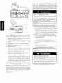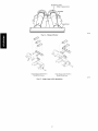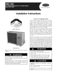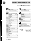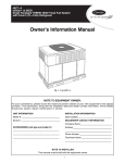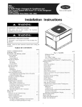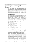
1
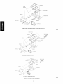
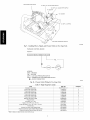
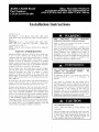
Installation Instructions
This kit is used on:
Two-Stage
(2 - 5 Tons) Models: 48DU,
577B, 577D, 677B, and 677D. (Two-Stage
48DT, 48XL, 48XT,
conversion
starts on
Page 2.)
Single-Stage
(1-1/2
- 5 Tons)
48VT, 574D,
577C, 674D,
conversion starts on Page 9.)
NOTE:
Read
installation.
the entire
SAFETY
Models:
677C,
48ES,
48EZ,
and PY3G.
instruction
manual
48VL,
Failure
to follow this
iniury, death or property
(Single-Stage
before
starting
the
CONSIDERATIONS
Improper installation,
adjustment,
alteration, service maintenance,
or use can cause explosion,
fire, electrical
shock,
or other
conditions
which may cause death, personal iniury, or property
damage.
Consult
a qualified
installer,
service agency,
distributor
or branch for information
or assistance. The
FIRE,
EXPLOSION,
POISONING,
PROPERTY
or your
qualified
CARBON
DAMAGE
warning
damage.
could
MONOXIDE
HAZARD
result
in personal
This conversion
kit shall be installed by a qualified service
agency in accordance
with the manufacturer's
instructions
and all applicable codes and requirements
of the authority
having
jurisdiction.
The
qualified
service
agency
is
responsible
for the proper
installation
of this kit. The
installation
is not proper and complete until the operation of
the converted
furnace
is checked
as specified
in the
manufacturer's
instructions
supplied in the kit.
installer or agency must use factory-authorized
kits or accessories
when modifying
this product. Refer to the individual
instructions
packaged with the kits or accessories when installing.
Follow all safety codes.
and work gloves. Have
instructions
thoroughly
included
in literature
building
codes,
and follow
and attached
the current
(NFGC) NFPA 54/ANSI
(NEC) NFPA 70.
In Canada
Canada
Wear safety glasses, protective
clothing,
a fire extinguisher
available. Read these
editions
Z223.1,
refer to the current
CAN/CSA-BI49.1
Installation
codes,
Recognize
safety
and
information.
or cautions
consult
local
of the National
and the National
editions
and Canadian
all warnings
to the unit.
Fuel Gas Code
Electrical
of the National
.2 Natural
Electrical
Gas
Code
Standards
and
symbol
z_X
When you see this symbol on the unit and in instructions
or manuals, be alert to the potential for personal injury. Understand
these
signal words:
DANGER,
WARNING,
and CAUTION.
These
words are used with the safety-alert
symbol. DANGER
identifies
the most serious hazards which will result in severe personal injury
or death. WARNING
sonal injury or death.
La n_gligeance
de suivre l'avis
blessures
personnelles,
la mort
proprietY.
suivant,
ou du
PAR
DE
peut causer des
dommage
fi la
of
Propane
Code CSA C22.1
This is the safety-alert
FEU,
EXPLOSION,
EMPOISONNEMENT
CARBON
DE
MONOXYDE,
RISQUE
DOMMAGE
A LA PROPRII_TI_
Cette trousse de conversion
doit _tre install_e
par un
Entrepreneur
qualifi_, selon les instructions
du fabricant et
doff se conformer
fi routes les exigences
et tout les codes
pertinents de l'autorit_
comp_tente.
L'Entrepreneur
qualifi_
est responsable,
et doff s'assurer
de bien suivre
les
instructions
dans cet avis. L'installation
sera consid_r_
conforme et rencontrant
les specifications
et instructions
du
fabriquant
qui sont inclus dans la trousse, seulement
apr_s
v_rification de l'op_ration
de la fournaise convertie.
signifies hazards which could result in perCAUTION
is used to identify unsafe practic-
es which may result in minor
erty damage. NOTE is used
result in enhanced installation,
personal injury or product and propto highlight
suggestions
which will
reliability, or operation.
[]NIT
OPERATION
Failure to follow
components.
HAZARD
this caution
may result in damage
to unit
Before converting
a unit to propane gas, remove the burner
assembly and inspect the heat exchanger tubes. If there are
V-shaped
NOx
baffles installed in the firing tubes,
Fig. 1). THEY
MUST
BE REMOVED
PRIOR
CONVERTING
THIS UNIT TO PROPANE
GAS.
(see
TO
Table
I-
Two-Stage
Kit Contents
ITEM
PART
Installation Instructions
NO.
QUANTITY
ItKCPLPCONV-
11
1
Propane Gas Orifice #50*
LH32RF070
3
Propane Gas Orifice #51 *
LH32RF067
3
Propane Gas Orifice #52*
LH32RF065
3
Propane Gas Orifice #56"
Propane Gas Orifice #54*
LH32RF060
3
LH62RF055
3
Propane Gas Orifice #56*
LH62RF047
3
Regulator Spring (92-0659)
Pressure Switch
EF39ZW026
2
HKO2LBO08
1
90 ° Elbow, 1/8 in. NPT
CAO5RAO01
2
Nipple, 1/8 in. NPT x 2 in. (51 mm)
CA01 CA010
1
Close Pipe Nipple, 1/8 in. NPT x 6/4 in. (19 mm)
Wire Harness
CA01CAO01
2
48DU400080
1
Propane Conversion Label (Rating Plate)
48VL500206
1
Propane Conversion Label (Installer Responsibility)
Propane Conversion Warning Label (Gas Valve)
Burner Insert
48VL500207
1
48DU500076
1
48GS5004651
6
• Refer to Table 4 to determine the correct orifice to use.
Firing Tube
ELECTRICALSHOCK
Failure to follow
iniury or death.
Before
NOx Baffle
A01051
Fig. 1 - Low NOx
Baffle
installing
HAZARD
this warning
or servicing
PERSONAL
INJURY
this warning
could
result
in personal
instructions
cover
NOTE:
KIT INTRODUCTION
the
installation
of
a
propane
gas
combination
automatic
This Two-Stage
40,000
kit is applicable
to 130,000
Btu/hr
to units with heating
installed
at high altitudes
inputs from
from
2001
ft
(610m) to 6000 ft (1829 m). It cannot be used for standard altitude
installation.
Standard
altitude conversion
(0-2001
ft) (0-610 m)
must use kit CPLPCONV013A00.
TWO-STAGE
KIT INSTALLATION
ELECTRICAL
Failure to follow
this warning
injury, death or property damage.
could
HAZARD
result
in personal
Gas supply
MUST
be shut off before
disconnecting
electrical power and proceeding with conversion.
wire from the flame sensor.
the brown
wire from the burner
Save screw.
slide out the entire
burner
the inlet of the heat exchanger
rack assembly
from
tubes for presence
of
V-shaped
NOx baffles (see Fig. 1). If baffles are present,
they must be removed
prior to converting
unit for propane
gas. Using needle-nose
pliers, remove NOx baffles, squeeze
sides of the baffle,
exchanger tubes.
IMPORTANT:
back to natural
11. Using
EXPLOSION,
cable from the sparker.
the screw securing
If it
if necessary,
is expected
to remove
from
the heat
that this unit will be converted
gas at a later time, these baffles should
for reuse. Otherwise
FIRE,
sparker
white flame sensor
wires
wires from the rollout
see Fig. 8.
orange
8. Remove
and green/yellow
violet
switch,
6. Disconnect
10. Inspect
AND USAGE
brown
and remove
7. Disconnect
9. Completely
unit.
gas valve regulator.
DESCRIPTION
To locate rollout
assembly.
conversion
kit on models
48DT, 48DU, 48XL,
48XT, 577B,
577D, 677B and 677D that are equipped
with a White Rodgers
2-stage
the gray, blue,
from the gas valve
switch.
stage and low stage.
These
the screw
attaching
the gas manifold
to the
and partially
slide out the entire burner
rack
from unit. Save screw.
5. Disconnect
This unit is designed to operate at a minimum 10.0 IN. W.C.
of manifold pressure on high stage with propane gas. Refer
to Table 4 for proper manifold
pressure settings for high
first, then power to unit.
the gas pipe from the gas valve.
4. Remove
basepan,
assembly
HAZARD
injury or death.
TWO-STAGE
turn off main
the front access panel from unit.
3. Disconnect
to follow
always
in personal
Location
1. Turn off gas supply
Failure
system,
result
power to system.
There may be more than one disconnect
switch. Tag disconnect switch with suitable warning label.
2. Remove
EXPLOSION,
could
be retained
the baffles may be discarded.
a 5/16 in. nut driver, remove
the manifold/gas
valve
Save these screws.
12. For 2-Stage 40,000
Remove the burners
assembly
the four screws securing
to the burner
assembly.
Btu/hr and 60,000 Btu/hr models only!
from the rack, save the screws. Remove
the snap ring from the end of each burner. Install burner
insert in the end of each burner with the flat sides of the
square
retain
vertical
burner
and
insert
horizontal.
Replace
(See
2 for
Fig.
the snap
correct
ring
orientation).
to
Replace
theburners
in therackusingthesaved
screws,
making
sure
closed
crossovers
ofburners
areateach
end.
13.Remove
thenatural
gasorifices
fromthemanifold
usinga
9/16in.wrench
andinstallthecorrect
propane
gasorifices
in themanifold
(SeeTable
4 toselect
correct
orificesize
basedon ratedinput.SeeFig.3 and6 for orifice
installation).
14.Replace
themanifold/gas
valveassembly
intotheburner
assembly
using
thefourscrews
saved
fromitem11.
15.Remove
theplugontheinletendofthegasvalve
usinga
3/16in.hexwrench.
16.Install
the1/8in.NPTx3/4in.(19ram)close
pipenipple
where
theplugwasremoved
(see
Fig.9).Usepipethread
dope
ortape
(field-supplied,
nmst
becertified
forusewith
propane
gas)foralljoints,making
surenotto getany
excess
inthepipeorvalve.
Next,installa1/8in.elbow,
a
1/8in.NPTx 3/4in.(19ram)close
pipenipple,
1/8in.
elbow,
1/8in.x NPT2 in.(51ram)nipple,
andalowgas
pressure
switch
asshown
inFig.9.
17.Remove
regulator
cover
screws
forbothhighandlowstage
gasregulators
(see
Fig.2).Save
regulator
cover
screws.
wires to (M). Connect
the brown
and green/yellow
wires to
(C).
28, Reconnect
the brown
wire from the burner
assembly
to the
sheet metal partition.
29, Slide burner rack assembly into base pan. Align burner rack
with screws on sheet metal partition
and slide assembly
back tight to the partition. Replace the screw attaching
burner rack to the base pan removed in step 4,
30, Remove
the
connect
1/8 in. pipe
a pressure
plug
manometer
on
the gas
the
manifold
and
(see Fig. 4).
J
_., ..........ST,C
.... STSC_W
ON/OFF SWITCH
(Propane
- White,
Nmural - Silver)
1/2" NPT
INLET
0
22IN
0
[5
lOIN
5MM]
[/8
2MMI
ORIFI(
1/2"
NPT
OUTLET
--
FLAME
SENSOR
--
IGNITOR
_
A07804
Fig. 2 - Two-Stage
18. Using
a screwdriver,
Gas Valve
remove
plastic
adjust screws from both
1
high and low stage gas regulators
adjust screws.
19. Remove regulator springs (silver) from
stage gas regulators (see Fig. 2). Discard
both high and low
regulator springs.
20. Install propane gas regulator
springs (white)
this kit. One into the low stage gas regulator
the high stage gas regulator (see Fig. 2).
adjust
turn clockwise
22. Install
flame
sensor,
orifice/main
relationship
prior to completing
conversion.
Partially slide burner rack assembly into unit.
pressure
the
orange
wire
switch and connect
from
the
(See
Fig. 3.)
combustion
air
it to the orange wire on the low
air pressure switch (see Fig. 10).
25. Reconnect the violet wires removed
and reinstall
the rollout
in item 5 to the rollout
switch.
26. Reconnect
orange sparker cable to sparker and reconnect
the white flame sensor wire to the flame sensor.
27. Reconnect
valve.
the remaining
Connect
the gray
wires removed
wires
to (HI).
in item 5 to the gas
Connect
Igniter, Flame Sensor,
Burner
Relationship
electrical
applications,
power
Orifice/Main
and gas supply
the gas pressure
to the unit. For
nmst not be less than
upstream of the gas supply connection to the gas valve and
downstream
of manual equipment shutoff valve.
The newly installed low gas pressure switch is a safety device used
to guard against adverse burner operating
characteristics
that can
burner
gas pressure switch (LGPS) equipped
with a 1/4 in. male
quick-connect
terminal.
The low gas pressure
switch
should
have one unconnected
orange
wire remaining.
Connect this wire to the vacant terminal on the combustion
switch
8MM MAX]
11,0 IN. W,C, or greater than 13 IN, W.C. at the unit
connection.
A 1/8-in. NPT plugged tapping, accessible for
test gauge
connection,
nmst be installed
immediately
into the low stage gas regulator.
9.5 turns (see Fig. 2).
igniter,
24. Disconnect
propane
screw into the high stage gas regulator.
adjust screw
turn clockwise
23. Verify
31. Reconnect
shipped with
and one into
13.5 turns (see Fig. 2).
plastic
[34
A07889
Fig. 3 - Two-Stage
21. Install plastic
37IN
(see Fig. 2). Save plastic
the blue
result from low gas supply pressure. Switch opens at not less than
6,5 IN, W.C. and closes at not greater than 10.2 IN, W.C.
This switch also prevents operation when the propane tank level is
low which can result in gas with a high concentration
of impurities,
additives, and residues that have settled to the bottom of the tank.
Operation
exchanger
under these
system,
This normally
under normal
can
cause
harm
to
the heat
open switch closes when gas is supplied to gas valve
operating
pressure.
The closed switch completes
control circuit.
Should
occur, the gas pressure
switch
circuit
conditions
an interruption
or reduction in gas supply
at switch drops below low gas pressure
setting,
and switch opens,
Any interruption
in control
(in which low gas pressure switch is wired) quickly closes
gas valve and stops gas flow to burners,
Table 2 - Two-Stage
Sequence of Operations
Inducer Pre-Purge Period: When the inducer motor comes up on high speed, the pressure switch closes, and the Infinity _ ignition control
on the furnace board begins a 15 sec pre-purge period. If the pressure switch fails to remain closed, the inducer will remain running. After
the pressure switch recloses, the Infinity ignition control will begin a 15 sec pre-purge period.
Trial-for-Ignition Sequence: The spark igniter will spark for 3 sec, the main gas valve relay contact closes to energize the gas valve on low
stage. After 5 sec, the igniter is de-energized and a 2-sec flame-proving period begins.
NOTE: The unit always lights on high speed inducer and low stage gas valve operation.
Flame-Proving: When the burner flame is proved at the flame-proving sensor, the furnace control determines what heating stage to run
based on feedback from the User Interface (UI). If the UI is asking for low stage gas heat, the ignition control will change the inducer speed
to low speed and keep the gas valve energized on low stage. If the UI is asking for high stage gas heat, the ignition control will maintain
running the inducer on high speed and energize the gas valve's high stage relay to increase gas flow.
Table
NAMEPLATE
3 - Two-Stage
Rated
Heating
Input,
Propane
Gas (2001-6000
ft [610-1829
RATED HEATING
HIGH STAGE
INPU% HIGH STAGE (BTU/HR)
m] Altitude)
INPUT PROPANE (BTU/HR)
LOW STAGE
40,000
38,000
26,000
60,000
57,000
39,000
90,000
79,000
58,500
115,000
103,000
75,000
130,000
116,000
84,500
FIRE
AND EXPLOSION
HAZARD
Failure to follow this warning
iniury and/or property damage.
could result in personal
Never test for gas leaks with an open flame. Use a
commercially available soap solution made specifically for
the detection of leaks to check all connections.
IMPORTANT:
Restart unit and leak check all gas connections
including the main service connection, gas valve, gas spuds, and
manifold pipe plug. All leaks must be repaired before firing unit.
MANIFOLD
PIPE PLUG
099019
Fig. 4 - Two-Stage
Burner Assembly
BURNER FLAME
(Blue in appearance)
BURNER
MANIFOLD
32. Fire unit and verify proper ignition and proper sequence of
operation (Table 2). See Table 4 for proper low stage and
high stage manifold pressure settings for your unit. Adjust
the gas valve setting for high and low stages by turning the
plastic adjustment screws clockwise to increase pressure and
counter-clockwise to decrease pressure for the respective
stages. Refer to Table 3 for required rated heating input
rates. Replace regulator cover screws when finished (see
Fig. 2).
33. With burner access panel removed, observe unit heating operation in both low stage operation and high stage operation. Watch burner flames to see if they are blue in appearance, and that the flames are approximately the same for
each burner (see Fig. 5).
34. Turn off unit, remove pressure manometer and replace the
1/8 in. pipe fitting on the gas manifold (see Fig. 4).
35. Attach warning label (P/N 48DU500076) to visible side of
gas valve.
36. Attach conversion label (P/N 48VL500206)
rating plate on exterior of unit.
above unit
C99021
Fig. 5 - Monoport
Burner
37. Attach completed conversion responsibility label (see Fig.
7, P/N 48VL500207) inside service access panel.
IMPORTANT:
Restart
including
the main
manifold
pipe plug.
unit and leak check
service
connection,
all gas connections
gas valve,
gas spuds,
38. After
all leaks are eliminated,
EXPLOSION,
FIRE
AND EXPLOSION
Failure to follow this warning
injury and/or property damage.
could
PERSONAL
Failure to follow
injury or death.
HAZARD
result
in personal
Never test for gas leaks with an open flame. Use a
commercially
available soap solution made specifically
for
the detection of leaks to check all connections.
replace service
panel.
and
INJURY
this warning
could
HAZARD
result
in personal
This unit is designed to operate at a minimum 10.0 IN. W.C.
of manifold pressure with propane gas. Refer to Table 4 for
proper manifold pressure settings.
BURNER
(3)
FLAME
SENSOR
MANIFOLD
ORIFICE
(3)
TWO-STAGE90,000 BTUHTO 130,000 BTUH UNITS
A08565
BURNER
INSERT
(3)
....
.\
\
r
_.
i
ORIENTATION
OF
BURNER
INSERT
FLAME
SENSOR
(3)
BURNER (3)
_
"__ORIFICE
SPARKER
-
GASVALVE
(3)
TWO-STAGE
60,000
BTUH
UNITS
ORIENTATION
OF
BURNER
INSERT
I
/_
PIPE
BURN ER RACK
PLUG
ORiFiCE
(2)
TWO-STAGE
40,000 BTUH UNITS
A08509
Fig. 6 - Two-Stage
Orifice
Installation
Table
PROPANE
4 - Propane
Gas Orifice
CONVERSION
KiT
Sizes and Manifold
RATING
Pressures
PLATE
(IN. W.C.)
CARRIER
CORP.
TH S APPL ANCE HAS BEEN CONVERTED TO USE PROPANE GAS FOR FUEL REFER TO K T NSTRUCT ONE FOR CONVERS ON PROCEDURES
USE PARTS SUPPLIED BY CARRIER CORPORATION AND iNSTALLED BY QUALiFiED PERSONNEL. SEE EXiSTiNG RATING PLATE FOR APPLIANCE
MODEL NO. AND iNPUT RATING,
NOTE:
Gas
derated
input
by 4% for
KK,TTNO.
rate
on
each
rating
1000
plate
ft.
is for
(305m)
above
installations
sea
up to
2000
in Canada
ft.
the
BiOta)
input
above
rating
CC;L;cCoONVoO_3Ao000
l_O_.O(O.'(_m_;_;v_a_Tse_)aievel
"
sea
must
)
MODELS
48DU
48DT 48XL 48XT
....
577B, 577D, 677B, 677D
48ES 48EZ 48VL 48VT 574D
.....
5770 674D 6770
PY3G
48DU, 48DT, 48XL, 48XT,
I
I
I
I
I
577B 577D 677B 677D
48ES, 48EZ, 48VL, 48VT, 574D .......
577C, 674D, 677C, PY3G
48ES, 48EZ, 48VL, 48VT, 574D,
577C, 674D, 677C, PY3G
_U,UOU
Orifce
ManiTold
I High /
Orifice
I ......
Manlro a
! High /
O[if ce
No
Press.
Low
No •
Hress
Low
No
I
i
677B
I
677D
5770
I
I
Oto2000ft
(0to610m)
55
altitudes
ft.
above
to
tFT,
m
It.
(610
to
610m
ABOVE
SEA
11.0-13.0
in. wc
11.0/5.0
56
I 10.7/4.8
56
I
!
I
1O.0/NA
55
!
I
11.O/NA
56
!
I
11.O/NA
56
!
I
11.0/NA
56
I
I
11.0/6.0
54
11.0/5.5
54
ll.O/NA
54
11.O/NA
I
I
ll.0/NA
54
11.0/NA
MO[ifoi_de pNrO_s
High / Low"
53
10.0/5.4
I
54
11.0/6.4
I
54
11.0/5.9
115 ODD
'
uaOn_ifi_e9N°_s"
High / Low
51
10.0/5.4
115 ODD
'
......
I MaOn_ifoi_d
e N°_s I
High / Low"
I
orifice No.
I
51
1O.0/NA
49
I
I
I
52
11.0/5.0
I
52
11.0/NA
50
I
I
52
10.6/4.8
52
1O.6/NA
51
11.0/5.0
54
!
I
t
I
I
11.014.9
11.015.2
I MO[i_de
NO_s
I High / Low" !
49
1O.O/NA
50
11"O/NA!
51
11"O/NA!
52
11.O/NA
NA
CONVERTI LE
(JOUR
I
I
-
53
11.0/5.5
53
11.O/NA
52
11.015.0
!
NOT APPLICABLE
ON
- YEAR)
!
53
11.0/NA
52
11.014.8
ll.O/NA
54
11.O/NA
54
11.0/5.0
53
11.0/6.1
10.015.4
I
I
54
11.0/5.4
I
10.7/NA
56
10.7/4.8
54
11.O/NA
54
11.O/NA
PLroew
ss"
TO PROPANE GAS
level.
!
I
CE GFiNI_RATEURD'AIR CHAUD A FiTI_
-
sea
LEVEL} U,S,A,
THIS FURNACE WAS CONVERTED
-
be
above
11.0/5.5
56
1 For Canadian Installations from 2000 to 4500 ft. (610 to 1372 m) use U.S.A. column 2001 to 3000 ft. (611 to 914m)
(DAY - MONTH
must
1372m)
5001to 6000ft.
i io_ttogt4mll(gt_to_2t9m>l(122Oto1_24ml
I (1525 to1829 m)
I
56
I
56
I
56
I
56
I
I
130 ODD
'
2000
ft.
12001to 3000 ft. 1. 3001to 4000ft. I 4001to 5000 ft.
1O.O/NA
53
1O.O/NA
M_ir_°Id/
4500
,NLET PRESSURE(min-max)'.
iNSTALLATiON
U_n_old/ ProewSS. 10.0/5.0
O[_i.ce 2Jo.
53
tou,uuu
48EZ 48VL 48VT 574D
674D, 677C, PY3G
OF
for
of 2000
!
I
48DU, 48DT, 48XL, 48XT,
577B, 577D, eZZB, e77D
577D
rating
altitudes
11.0/6.0
56
90 ODD
'
577B
input
I
I
48DU, 48DT, 48XL, 48XT,
577B, 577D, 677B, 677D
I
the
10% for
10.0/5.0
55
w_n_om/ _wSS.
i . Od.fice No
I
MamTolo wress
High / Low"
48ES, 48EZ, 48Vh, 48VT, 574D, 5770,
674D, 677C, PY3G
48DU, 48DT, 48XL, 48XT,
by
I
I
eu,uuu
.....
_U UUU
'
I
in U.S.A.
be derated
ALTITUDE
HIGHSTAGE'
(Btu/hr)
I
40 ODD
'
....
40 0O0
'
- ....
level,
FUEL USED: PROPANE GAS
_EPLATEINPUT,
APPLIANCE
48ES
level,
52
11.O/NA
48VL500205
POUR
- MOIS - ANNEE)
DEL'ENSEMBLE
N°:
KITNO.:CPLPCONV013A00
(0~2000ft.(0~610m)
CPLPCONV013A00
(0~ 2000ft.(0-610rn)abovesealevel),
CPLPC0NV014A00
(2001~6000ft.(611~1829m)
abovesealevel)
CPLPCONV014A00
(2001~6000ft.(611~1829m)
abovesealevel)
BY:
PAR:
(Name and address of organization
making
this conversion),
which accepts
the responsibilily
that this conversion
has
been
properly
made,
(nomet adresse de I'organisme qui a effectue la conversion),
qui accepte I' entriere responsabilite de la conversion.
48VL500207
/
A08491
Fig. 7 - Conversion
Responsibility
Label
SWITCH
BURNER
BRACKET
C00150
Fig. 8 - Two-Stage
Burner
Bracket
TWO -STAGE GAS VALVE
1/8 NPTx 3/4 CLOSE PIPE NIPPLE
1/8 NPTx 3/4 CLOSE PIPE NIPPLE
1/8 ELBOW
1/8 ELBOW
1/8 NPTx2
LOW GAS PRESSURE
NIPPLE
SWITCH
A06488B
Fig. 9 - Installing
FURNACE
Elbows,
Nipples,
CONTROL
and Pressure
Switch
on Two-Stage
Units
BOARD
PLUG P1
1 2345678
c,
YEL
ORN -_
ORN _--
LEGEND
ORN = ORANGE
YEL = YELLOW
LGPS = LOW GAS PRESSURE SWITCH
CAPS = COMBUSTION
AIR PRESSURE
•
SWITCH
= QUICK CONNECTION
A06487
Fig. 10 - Pressure
Table
Switch Wiring
5 - Single-Stage
ITEM
Installation
Instructions
Kit
Units
Contents
PART NO.
IIKCPLPCONV-11
QUANTITY
1
Propane Gas Orifice #50*
LH32RF070
3
Propane Gas Orifice #51 *
LH32RF067
3
Propane Gas Orifice #52*
LH32RF065
3
Propane Gas Orifice #53*
LH32RF060
LH32RF055
3
3
LH32RF047
3
EF39ZW023
1
Propane Gas Orifice #54*
Propane Gas Orifice #56*
Regulator Spring (92-0659)
Pressure Switch
HK02LB008
1
90 ° Elbow, 1/8 in. NPT
CA05RA001
2
Nipple, 1/8 in. NPT x 2 in. (51 mm)
CA01CA010
CA01CA001
1
2
48DU400080
1
48VL500206
1
48VL500207
1
48DU500076
1
Close Pipe Nipple,
Propane
Propane
for Two-Stage
1/8 in. NPT x 3/4 in. (19 mm)
Wire Harness
Conversion
Conversion
Label (Rating Plate)
Label (Installer Responsibility)
Propane Conversion Warning Label (Gas Valve)
• Refer to Table 4 to determine the correct orifice to use.
SINGLE-STAGE
These
instructions
KIT
cover
the
INTRODUCTION
installation
of
a
11. Using
propane
gas
conversion kit on models 48ES, 48EZ, 48VL, 48VT, 574D, 577C,
674D, 677C and PY3G that are equipped
with a White Rodgers
single-stage
automatic
This single-stage
12. Remove
AND
kit is applicable
Btu/hr
USAGE
to units with heating
installed
40,000
to 130,000
(610m)
altitude
to 6000 fl, (1829 m), They cannot be used
installation,
Standard
altitude
conversion
(0-610
m) must use kit CPLPCONV013A00,
SINGLE-STAGE
at high altitudes
KIT
the natural
gas orifices
inputs from
from
2001
fl
EXPLOSION,
for standard
(0-2001
fl)
INSTALLATION
ELECTRICAL
Failure to follow
this warning
iniury, death or property damage.
result
the manifold/gas
assembly
valve
in personal
16. Remove
regulator
cover
Fig. 11). Save regulator
Before
installing
HAZARD
or servicing
could
system,
result
always
in personal
turn off main
power to system.
There may be more than one disconnect
switch. Tag disconnect switch with suitable warning label.
1. Turn off gas supply
2. Remove
a screwdriver,
the
basepan,
assembly
screw
attaching
5. Disconnect
and remove
To locate rollout
screw
from
sparker
7. Disconnect
yellow
flame sensor
the screw securing
the gas regulator
(see
cover screw.
remove
the
plastic
regulator
adjust
(see Fig. 11). Save plastic reg-
19. Install propane gas regulator
this kit. (See Fig. 11).
spring
shipped
with
20. Install
into
regulator,
turn
plastic
adjust
screw
(white)
the
gas
13.5 turns (see Fig. 11).
igniter,
ignitor,
flame
sensor,
manifold
entire
to the
burner
rack
gas pressure
quick-connect
switch (LGPS) equipped
terminal.
The low
should
have one unconnected
Connect this wire to the vacant
orifice/main
burner
air pressure
with a 1/4 in. male
gas pressure
switch
orange
wire remaining.
terminal on the combustion
switch (see Fig. 19).
cable from the sparker.
PLASTIC
wire from the flame sensor.
the brown
wire from the burner
Save screw.
9. Completely
unit.
and a low gas
switch, see Fig. 17.
orange
assembly.
(see Fig. 18). Use pipe thread
must be certified for use with
making sure not to get any
22. Disconnect
the orange
wire from the combustion
air
pressure switch and connect it to the orange wire on the low
the gray and brown wires from the gas valve
blue wires from the rollout switch.
6. Disconnect
8. Remove
gas
the
using a
relationship
prior to completing
conversion.
(See Fig. 12.)
Partially slide burner rack assembly into unit.
to unit.
the
and partially
slide out
from unit. Save screw.
the burner
(see
21. Verify
the gas pipe from the gas valve.
4. Remove
into
18. Remove regulator spring (silver) from the gas regulator
Fig. 11. Discard regulator spring.
clockwise
the front access panel from unit.
3. Disconnect
NOTE:
first, then power
using a
from item 11.
elbow, 1/8 in. x NPT 2 in. (51 mm) nipple,
pressure switch as shown in Fig. 18.
screw from the gas regulator
ulator adjust screw.
this warning
assembly
using the four screws saved
14. Remove the plug on the inlet end of the gas valve
3/16 in. hex wrench.
17. Using
Failure to follow
injury or death.
the manifold
excess in the pipe or valve. Next, install a 1/8 in. elbow, a
1/8 in. NPT x 3/4 in. (19 mm) close pipe nipple, 1/8 in.
Gas supply
MUST
be shut off before
disconnecting
electrical power and proceeding with conversion.
ELECTRICALSHOCK
from
assembly.
15. Install the 1/8 in. NPT x 3/4 in. (19 mm) close pipe nipple
HAZARD
could
to the burner
installation).
13. Replace
where the plug was removed
dope or tape (field-supplied,
propane gas) for all joints,
FIRE,
the four screws securing
assembly
9/16 in. wrench and install the correct propane gas orifices
in the manifold
(See Table 4 to select correct orifice size
based on rated input. See Fig. 12 and 15 for orifice
gas valve regulator.
DESCRIPTION
a 5/16 in. nut driver, remove
the manifold/gas
valve
Save these screws.
slide out the entire
burner
rack assembly
REGULATOR SPRING
(PROPANE - WHITE
from
NATURAL
- SILVER)
GAS PRESSURE
10. Inspect
the inlet of the heat exchanger
tubes for presence
of
V-shaped
NOx baffles (see Fig. 1). If baffles are present,
they must be removed prior to converting
unit for propane
gas. Using needle-nose
pliers, remove NOx baffles, squeeze
sides of the baffle, if necessary, to remove from the heat
exchanger
tubes.
MANIFOLD
IMPORTANT:
back to natural
for reuse.
If it
is expected
that this unit will be converted
gas at a later time, these baffles
Otherwise
the baffles may be discarded.
should
be retained
1/2' NPT OUTLET
_t_"
A07808
Fig. 11 - Single-Stage
Gas
Valve
This normally
open switch
closes when gas is supplied
to gas valve
under normal operating
pressure.
The dosed
switch completes
control circuit. Should an interruption
or reduction in gas supply
occur,
switch
the gas pressure at switch drops below low gas pressure
setting,
and switch opens.
Any interruption
in control
circuit (in which low gas pressure switch
gas valve and stops gas flow to burners.
FIRE
AND EXPLOSION
manifold
ORIFICE_
1 5_I
[34
unit
23. Reconnect
switch
Igniter,
Flame
Sensor,
and reinstall
the rollout
pearance,
25. Reconnect
the gray and brown
the burner
rack assembly
to the
into base pan. Align burner
connect
the
1/8
in. pipe
a pressure
29. Reconnect
plug
manometer
electrical
power
on the
gas manifold
IMPORTANT:
including
manifold
and gas supply
A 1/8-in. NPT plugged
connection,
must be
manometer
and replace
label (P/N 48DU500076)
Restart
unit
the main service
to visible
48VL500206)
and leak check
connection,
the
(see Fig. 13).
side of
above
unit
(see Fig.
all gas connections
gas valve,
gas spuds,
pipe plug.
and
FIRE
tapping,
installed
6.5 IN. W.C. and closes at not greater
Never
test
commercially
the detection
and
36. After
than 10.2 IN. W.C.
This switch also prevents operation when the propane tank level is
low which can result in gas with a high concentration
of impurities,
additives, and residues that have settled to the bottom of the tank.
can
cause
harm
to the
AND EXPLOSION
HAZARD
Failure to follow
this warning
iniury and/or property damage.
accessible for
immediately
The newly installed low gas pressure switch is a safety device used
to guard against adverse burner operating
characteristics
that can
result from low gas supply pressure. Switch opens at not less than
conditions
pressure
to the unit. For
upstream of the gas supply connection
to the gas valve
downstream
of manual equipment shutoff valve.
under these
system.
the same for
(see Fig. 13).
propane applications,
the gas pressure nmst not be less than
11.0 IN. W.C. or greater than 13 IN. W.C. at the unit
connection.
test gauge
(see Fig. 11).
35. Attach completed
conversion
responsibility
label
7, P/N 48VL500207)
inside service access panel.
rack
with screws on sheet metal partition and slide assembly
back tight to the partition.
Replace the screw attaching the
burner rack to the base pan removed in step 4.
28. Remove
of
to decrease pressure. Refer
heating input rates. Replace
34. Attach conversion
label (P/N
rating plate on exterior of unit.
sheet metal partition.
27. Slide burner
sequence
(see Fig. 14).
33. Attach warning
gas valve.
in item 5 to
assembly
and
firing unit.
and proper
1/8 in. pipe fitting on the gas manifold
the gas valve.
wire from
gas spuds,
before
and that the flames are approximately
32. Turn off unit, remove
switch.
orange sparker cable to sparker and reconnect
flame sensor wire to the flame sensor.
the brown
ignition
cover screws when finished
each burner
in item 5 to the rollout
24. Reconnect
the yellow
26. Reconnect
proper
all gas connections
31. With burner access panel removed, observe unit heating operation. Watch burner flames to see if they are blue in ap-
Orifice/Main
wires removed
an personal
gas valve,
pipe plug. All leaks must be repaired
regulator
8 M MAX]
Burner Relationship
the blue wires removed
result
and leak check
connection,
pressure and counter-clockwise
to Table 7 for required
rated
A07890
Fig. 12 - Single-Stage
could
operation (Table 6). See Table 4 for proper manifold pressure setting for your unit. Adjust the gas valve setting by
turning the plastic adjustment
screws clockwise
to increase
I6NITOR
Operation
exchanger
Restart
the main service
30. Fire unit and verify
FLAME
SENSOR
doses
for gas leaks with
an open flame. Use a
available soap solution made specifically
for
of leaks to check all connections.
IMPORTANT:
including
quickly
HAZARD
Failure to follow
this warning
iniury and/or property damage.
Never
test
commercially
the detection
is wired)
heat
10
could
result
in personal
for gas leaks with
an open flame. Use a
available soap solution made specifically
for
of leaks to check all connections.
all leaks are elinfinated,
replace service
panel.
and
Table 6 - Single-Stage
Sequence of Operations
Trial-for-Ignition Sequence: The ignition sequence is to immediately energize the inducer motor on a call for heat. Within approximately 5
sec of the call for heat, the gas valve will open and the igniter will spark. Seven sec will be allowed to prove flame sense on the far burner.
Flame-Proving: Once flame is proven, the control will wait an additional 45 sec to energize the indoor blower motor. On removal of the call
for heat, the gas valve will immediately shut down, the inducer motor will run for an additional 5 sec, and the indoor blower will run for an
additional 45 sec (naininmm).
Table 7 - Single-Stage
NAMEPLATE
Rated Heating Input, Propane Gas (2001-6000
INPUT (BTU/HR)
ft [610-1829 m] Altitude)
RATED HEATING
INPUT PROPANE
40,000
38,000
60,000
53,000
90,000
79,000
115,000
103,000
130,000
116,000
(BTU/HR)
/
Pipe Plug
/
Manifold
A07872
Fig. 13 - Single-Stage
Burner
11
Assembly
BURNER
FLAME
(Blue
inappearance)
BURNER
MANIFOLD
A07805
Fig. 14 - Monoport
J
Burner
:
/
/
/
/
Single-Stage
90,000 BTUH to
130,000 BTUH Units
Single-Stage
40,000 BTUH to
60,000 BTUH Units
A07873
Fig. 15 - Single-Stage
Orifice
12
Installation
Rollout Switch
Burner Bracket
A07874
Fig. 16 - Single-Stage
Burner
13
Bracket
LOW GAS PRESSURE
SINGLE-STAGE
SWITCH
\
1/8 NPTx 2 NIPPLE
GAS VALVE
ELBOW
1/8 NPTx 3/4 CLOSE PiPE NIPPLE
1/8 NPTx 3/4 CLOSE PIPE NIPPLE
A07809
Fig. 17 - Installing
FURNACE
Elbows,
Nipples,
and Pressure
Switch
on Single-Stage
Units
CONTROLBOARD
PLUG J2
1
2345678
c,
ORN
LEGEND
ORN = ORANGE
YEL= YELLOW
LGPS = LOW GAS PRESSURE SWITCH
CAPS = COMBUSTION AIR PRESSURE SWITCH
•
= QUICK CONNECTION
A07806
Fig. 18 - Pressure
Copyright
2008 CAC / BDP •
Manufacturer
reserves
7310 W. Morris St. •
the right to change,
Indianapolis,
IN 46231
at any time, specifications
Switch
Wiring
Printed in U,S,A,
and designs
without
for Single-Stage
Edition
notice and without
14
Units
10/08
Catalog
obligations,
Replaces:
Date:
No: IIKCPLPCONV-11
IIKCPLPCONV-
09