1
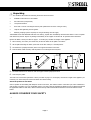
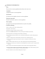
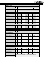
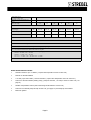
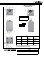
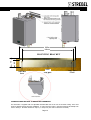
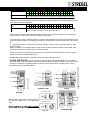
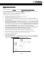
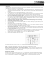
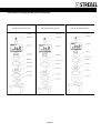
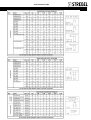
Strebel S-CB Wall Hung Condensing Boiler Range Installation, Operating & Maintenance Manual Page 1 Version 10 2011 pubdt 1 SAFETY GUIDELINES This manual is written for: The installer System design engineer The service engineer The following symbol is used in this manual: Giving extra attention for the safety of persons and their surrounding. Read all these instructions before commencing installation. Read the instructions before installation, to ensure that all work is done correctly. Keep these instructions together with the user manual near the boiler for quick reference. The appliance should be installed by a skilled installer such as GAS SAFE registered & electrical work by a qualified person, all according to national and regional standards Failure to comply with these regulations could lead to prosecution and deem the warranty invalid. This appliance must be installed in accordance with the rules that apply and only be used in an adequately ventilated space conforming to standards in place. Without written approval of the manufacturer the internals of the boiler may not be changed. When these changes are executed without approval, the boiler certification and warranty is invalid. Commissioning, maintenance and repair must be done by a skilled installer/engineer, according to this manual and all applicable standards and regulations. What should one do when there is the smell of gas: Don't use any electrical equipment. Don't press any switches. Close the gas supply. Ventilate the room (open the windows and/or outside boiler room doors). Warn the installer immediately. Read the instruction manual carefully before you install the boiler. The manufacturer / supplier is not liable for any damage caused by inaccurately following any of these installation instructions. Only original parts may be used when carrying out any repair or service works. CAUTION THE BOILER CAN START UP WITHOUT WARNING ISOLATE THE BOILER BEFORE ATTEMPTING ANY WORK BEWARE SURFACES IN BOILER ROOMS CAN GET VERY HOT AND CAUSE INJURY ALWAYS ADHERE TO YOUR OWN COMPANY’S HEALTH AND SAFETY RULES YOUR SAFETY IS OF PARAMOUNT IMPORTANCE. BE AWARE OF WHAT IS HAPPENING AROUND YOU AT ALL TIMES AND CONSIDER YOUR SAFETY AND THE SAFETY OF OTHERS. Page 2 Contents SAFETY GUIDELINES Page 2 INSTALLATION OF THE SCB UNPACKING 4 INTRODUCTION 5 IMPORTANT INFORMATION 6 GENERAL DATA S-CB BOILERS 7&8 4. DIMENSIONS CONNECTIONS FLUES 9 &10 6. FLUE RUN & FLUE TERMINAL INFORMATION 11&12 PLACING & FITTING THE BOILER 13 & 14 HYDRAULIC INFORMATION 15,16 & 17 CONDENSE WATER DRAIN 18 LOW LOSS HEADER DIMENSIONS 19 TYPICAL SYSTEM LAYOUTS 20 & 21 ROOF TOP PLANT ROOM HYDRAULIC LAYOUT 22 LOW LOSS HEADER & PLATE HEAT EXCHANGER SEPARATION OF SYSTEM 23 PLATE HEAT EXCHANGER SEPARATION OF SYSTEM 24 INSTALLATION INSTRUCTIONS FOR THE ELECTRICIAN 25 CONNECTION STRIP 25 CONTROL CONNECTIONS 1 TO 8 26 CONTROL CONNECTIONS 9 TO 34 27 SENSOR VALUES 28 CONTROL SCHEMES 29 & 30 INTERNAL WIRING 31 & 32 COMMISSIONING 33 TO 38 GAS CONVERSION 38 INSPECTION AND MAINTENANCE 39 & 40 INSTRUCTION TO THE USER 40 FLUE CONVERSION KITS 41 FLUE RESISTANCE TABLE 42 Page 3 Unpacking The Strebel S CB includes the following documents and accessories: Installation instructions for the installer. User instruction (incorporated). 1 suspension bracket. Fuses and 3 nuts for mounting the burner plate (attached to the front of the gas valve). 1 siphon with tightening nut and gasket. Reducing couplings (where required) for flue gas discharge and air supply. THE BOILER IS SET FOR NATURAL GAS G20. On delivery, unpack and immediately check that the Strebel S-CB is complete and without any defects. Report any damage immediately to the supplier or Strebel Ltd. Re pack the Boiler until fitted. Beware the Boiler is Heavy see table on page 7. To avoid injury consider the weight of the appliance. 1. After removing the carton, the easiest way to take the boiler off the pallet is as follows: 2. Lift the pallet including the boiler (at the side of the flue outlet) to a vertical position. 3. The boiler has a polystyrene block, which now supports the Boiler on the floor. 4. Push the Boiler a little forward, until the pallet is not touching the floor anymore. 2 1 4 5 6 3 5. The boiler stands now on the flow- and return pipes and the polystyrene block. 6. Take away the pallet. The boiler can now be lifted (the Boiler is Heavy see table on page 7 to avoid injury consider the weight of the appliance) for mounting. You must unclip and remove the Boiler door before lifting. Select the position for the Boiler Select a position in the building with adequate access to the front, side and the bottom of the boiler (for future maintenance and servicing) mounting on a non combustible surface. On every side of the boiler at least 50 mm of clearance should be applied to walls or wall units, 350 mm above the top side of the boiler and 250 mm from the bottom of the boiler. ALWAYS CONSIDER YOUR SAFETY. Page 4 INTRODUCTION Warning: For trouble free operation of the boiler, and to be assured of the full guarantee, the following items are required together with other stipulations in this manual: A. An automatic air and dirt separator (alternative pages 23&24)must be installed in the system and a strainer installed in the return pipework. Installation of ancillaries and devices must be installed as shown on pages 19 or 20. B. Minimum static water pressure must be more than 1 bar. Maximum 4 bar and 6 bar on request at same cost. C. The system is flushed, free of water leaks, water tested, and additive utilised where necessary. (see page 17 and D. page 23/24 for information relating to old systems). The Boiler must be level. The Boiler must be vented, the auto air vent cap (where fitted) must be open or manual air vent (where fitted) utilised. Open all system auto air vents . E. Low and high water cut out pressure switches ( usually in the fill unit) connected in the Boiler volt free control circuit in series with other controls on terminals 13 & 14 (PAGE 25) or by 0 volt when using external 0 to 10 volt control by others. See pages 25,26&27 F. Control of Boiler on/off must never be by interruption of the mains supply. G. When using a common flue, the flue system must be in negative pressure if not contact Strebel. These instructions are written for the installer of Strebel products and together with the Electrical Control And Commissioning Manual contain all necessary information on the installation and adjustment of S-CB boilers. Please read all these instructions fully before installation to ensure that all work is done safely and correctly. We suggest that you keep these instructions near the boiler. Operation of the Strebel S-CB Boiler The heating boilers from the Strebel S-CB series are heating boilers with maximum high efficiency. Such performance is reached by, among other things, using a special heat exchanger made of stainless steel. The heat exchanger allows flue gases to cool down below condensation point, condensing the flue gases and releasing extra heat. This has a positive impact on the efficiency, exceeding 100%net calorific. S-CB flue gases have a low temperature (below 85°C), the boiler needs to have a high efficiency approved stainless steel or plastic flue system .Aluminium flue systems are not allowed to be connected to these boilers. Adequate drain points must be added to the flue system with a “u” trap. Controls The Strebel S-CB Boiler adjusts to the demand for heat by using flame modulation and external controls. That is on the basis of 1) 0 to 10 volt control. 2) Strebel optimiser control. 3) Built in weather compensation with an outside detector. 4) RC or E-BUS .For RC or E-Bus system, see separate booklet. The boiler control is equipped with: Control for a DHW Cylinder with a diverter valve or a pump (pump via a relay both not supplied) Connection for a Heating pump via a relay (pump and relay not supplied) Connection for a room thermostat, on/off control, optimiser or 0 to 10 volt control. Frost protection Frost protection does not protect the system or system pumps. It protects the boiler. Frost protect the system by fitting devices to link out any timer controls. In a frost condition (at 7° Boiler temperature) the Boiler internal pump starts. When the boiler water temperature falls down to 3°C, the burner is also ignited. This operation will cease as soon as the boiler temperature has reached 10°C. Cascade control Using the integrated cascade control, a maximum of 12 boilers can be controlled in a cascade configuration. The Cascade has in-built full logic step control. The Boiler will require a Flow temperature sensor and 2 wires to each boiler in a daisy chain. When using a common flue that is not in negative pressure the cascade control must be used 0-10 VDC connection The boiler is equipped to take a 0-10 VDC signal from a controller by others (set at time of commissioning) Controlling up to 12 boilers (temperature) in cascade, utilising the built in cascade manager. (0 Volt is no heat demand.) The Boiler will require a Flow temperature sensor at extra cost and 2 wire link to all boilers in the cascade. Page 5 IMPORTANT INFORMATION Flues Flues must be to current regulations and conform to the clean air act. Ventilation Ventilation must be to current regulations Gas Pressure Gas Pressure at the Appliance must be to current regulations Electrical connections Electrical connections must be to current regulations. Water Quality See pages 27 & 28 for important information on system water quality. Condensate Drainage Points to remember when routing condense pipework. The pipework must be plastic. Run pipework sloping to outside as steeply as possible. Be aware that condensate can freeze so where possible pipework should route internally. Increasing pipework size could help prevent blockage from freezing. Pipework running externally should be as short as possible and insulated also consider avoiding exposed positions. Consider trace heating which is thermostatically controlled for the condensate pipework. Consider an automatic pump unit specifically for removal of condensate if no drain point is easily accessible. Ideally condensate should connect to the sewer drain complying with local and national regulations. BS 6644 states Alternatively, the condensate can be discharged into the rainwater system or a purpose-made soak-away. Always comply with local and National regulations and if in doubt contact the appropriate authority. Strebel will commission Boilers on the understanding that the suitability of the condense drainage system is checked by others and that compliance is always checked by others. See other information on the condensate drainage/trap on Page 15 Page 6 GENERAL DATA Product Identification Number CE 0063 BP3254 Dimensions (h x w x d) mm 842 x 476 x 486 Classification 898 x 476 x 677 II2H3P (for NL II2L3P) Gas Appliance Type B23; C13X, C23X, C33X, C43X, C53X, C63X, C83X Type Boiler 60 80 100 120 150 180 Water content est. Litre 3.9 5 6.5 8.3 10.4 12.9 Weight (empty) kg 46 73 78 83 92 101 Flow/Return connection (boiler) inch R 1” R 1” R 1” R 1” R 1¼” R 1¼” Flow/Return connection (T-piece) inch Rp 1¼” Rp1¼” Rp 1¼” Rp 1¼” Rp 1½” Rp 1½” Gas connection inch R ¾” R ¾” R ¾” R ¾” R 1” R 1” Flue duct flue/air inlet mm 80/125 80/125 100/150 100/150 100/150 100/150 Parallel connection mm 80- 80 80-80 100-100 100-100 130-130 130-130 Nominal input min./max. (Net) kW 11.0-56.0 14.6-74.0 17.2-92.0 22.0-111 34.0-138 43.0-166 Nom. output 80/60 at 100% kW 10.6-53.9 14.0-70.9 16.5-88.2 20.9-106 32.6-132 41.4-160 Nom. output 50/30 at 100% kW 11.4-57.8 15.2-77.2 18.0-96.0 23.1-116 35.5-144 45.2-175 Nom. output 37/30 at 30% kW 11.8-60.3 15.7-79.8 18.6-99.2 23.8-120 36.7-149 46.4-179 Efficiency 40/30ºC DIN 4702-8 % GAS CONSUMPTION [EN437] Natural gas G25 min. m³st/h 1.35 1.80 2.12 2.71 4.18 5.29 Natural gas G25 max. m³st/h 6.89 9.11 11.32 13.66 16.98 20.43 Natural gas G20 min. m³st/h 1.16 1.54 1.82 2.33 3.60 4.55 Natural gas G20 max. m³st/h 5.93 7.83 9.74 11.75 14.60 17.57 Propane gas G31 min. m³st/h 0.45 0.60 0.70 0.90 1.39 1.76 Propane gas G31 max. m³st/h 2.29 3.03 3.76 4.54 5.65 6.79 Gas supply pressure nom. G25 mBar 25 25 25 25 25 25 Gas supply pressure nom. G20 mBar 20 20 20 20 20 20 Gas supply pressure nom. G31 mBar 30/37 30/37 30/37 30/37 30/37 30/37 CENTRAL HEATING up to 110.6 % within the range TECHNICAL DETAILS CO2- flue gas G25/G20 min.*** % 8.5 8.5 8.5 8.5 8.5 8.5 CO2- flue gas G25/G20 max.*** % 8.8 8.8 8.8 8.8 8.8 8.8 CO2- flue gas G31 min.*** % 9.3 9.3 9.3 9.3 9.3 9.3 CO2- flue gas G31 max.*** % 10.0 10.0 10.0 10.0 10.0 10.0 NOx - class [EN483 / EN15420] NOx emission levels of less Page 7 than 40 mg/kWh within the SCB range NOx emission at 0% O2 max.80/60 * Temp. flue gas est. @ comb. air temp 20ºC Available pressure for the Flue system** °C ≈ 85-95 Pa 200 Max. flow temp. °C Power supply V / Hz Power consumption W Protection class 90 90 90 90 90 90 230 / 50 230 / 50 230 / 50 230 / 50 230 / 50 230 / 50 355 355 355 375 460 460 IPX4D IPX4D IPX4D IPX4D IPX4D IPX4D NOTES * Emissions measured during unit certification ** Maximum combined resistance of flue gas and air supply piping at high fire. *** CO2 of the unit measured/set without the boiler door in place **** Below a table is given in which the min. and max. gas supply pressures are mentioned acc. To EN437. G25 min. = 20 mbar / max. = 30 mbar G20 min. = 17 mbar / max. = 25 mbar G31 > Pnom = 30 mbar > min. = 25 mbar / max. = 35 mbar G31 > Pnom = 37 mbar > min. = 25 mbar / max. = 45 mbar Boiler inbuilt features includes: Cascade control for up to 12 boilers ( requires flow temperature sensor at extra cost ) Remote run & fault indication 0-10 VDC ( input from others ) control connection ( requires flow temperature sensor at extra cost ) Control for external calorifier primary pump ( pump not included ) via relay & sensor at extra cost ( see page 21) Weather compensation control (with north facing outside detector at extra cost) Control for an external pump via relay at extra cost, (see page 21) external pump not included. Electronic Ignition. Page 8 SCB 60Coaxial to !120Flue Co-Axial/concentric Standard SCB 60—120 connection at the rear. Twin Pipe Flue using adaptors at extra cost A SCB A B 155 150 80 100 120 112 135 60 B Install horizontal Flue parts under 5.2% fall in the direction of the boiler Coaxial flue is standard supply on 60kw to 120kw Boilers. SCB60/80 SCB 100/120 F/R Flow/Return 1¼” Male 1¼” Male A1/FG Flue exhaust/Air inlet 80mm 125mm 100mm 150mm C Condensate Hose 25/21 x 750 Hose 25/21 x 750 G Gas ¾” Male ¾” Male Parallel Flue adaptors are available for the SCB 60,80,100,120 Boilers and are shown below. See drawings on page 41 Flue exhaust at the rear and air inlet at the front Install horizontal Flue parts under 5.2% fall in the direction of the boiler With adequate drain points S-CB Part No. AIR/ EXHAUST Dimension A/B 60 6-E61.001.162 80 80 112 /135 80 6-E61.001.163 80 80 112 /135 100/120 6-E61.001.164 100 100 112 /135 Page 9 SCB 150 & 180 PARALLEL FLUES F/R Flow/Return 1½” Male A1/FG Flue exhaust/Air inlet 130 /130 mm C Condensate Hose 25/21 x 750 G Gas 1” Male Co-Axial/concentric connection at the rear. Separate exhaust and air inlet connections are: Flue exhaust at the rear and air inlet at the front Install horizontal Flue parts under 5.2% fall in the direction of the boiler (more than 5 centimetre for every linear metre) complete with extra drain points with a 60mm water trap. Site Air intake down- wards at the terminal Page 10 FLUE RUN & FLUE TERMINAL INFORMATION The SCB Boiler has a fan pressure capable of overcoming 200pa of Flue resistance and Air inlet resistance both added together. See the Table on page 42 for flue part resistances. Flue positioning should avoid flue products being drawn in by other Boilers see the information below. When using separate air intakes these should be at least 600 mm and ideally 1mt away from a flue exhaust. Supply Air can always be taken from an adequately ventilated Boiler Room. Installers must check that Flues comply with the clean air act as defined by the local authority . See BS6644 (2005) BS5440 (2000) IGE/UP/10 (ed 2) Flues must be to current regulations. FLAT SURFACE FLUE POSITIONS Co Axial Flue Flue Exhaust Co Axial Flue 600mm 600mm 600mm 600 mm Air Intake 600mm WALL Parapet, Wall etc. Flue exhaust locations will be the same as those shown on the next page however the 600 mm distance from the air intakes must be maintained Flue Exhaust Co Axial Flue 600mm Air Intake Page 11 COAXIAL FLUE & FLUE EXHAUST, PITCHED ROOF & WALL POSITIONS D D C A W D Above 70 Kw net input G Below 70kw net input 2000mm G From Ground W Side of opening 1000 mm Window W Side of opening 300mm Window A Adjacent to a Terminal A Adjacent to a Terminal V Vertically from 1500 mm a Terminal V Vertically from 1500 mm a Terminal C Internal or External Corner 300 mm C Internal or External Corner 300 mm P Distance from Roof Line 600 mm P Distance from Roof Line 600 mm Distance 600mm D Distance 500mm M Measurement 600mm M Measurement 300mm D From Ground V 600 mm P P 2000mm 300 mm M G 300mm Plan view of 3 SCB’s with coaxial flues OUTSIDE WALL Position of Coaxial Flues must be 600 apart. If this is not possible consider exhaust only and air intake from a correctly ventilated room. Consider a ducted (plastic Flue pipe complies) air inlet from a position on the same wall 600mm away from the exhaust and 300mm (see above ) from ground level. Check the flue and air inlet resistances on page 42. Flues must be to current regulations. Page 12 PLACING & FITTING THE BOILER CONSIDER THE FOLLOWING Prepare the Boiler for mounting on a non combustible surface. Determine the positions for the flow and return pipes using the suspension bracket (see next page) or a suspension frame, if any. When marking the holes, ensure that the suspension bracket or frame is level. Drill the holes for the flow and return pipes if required then hook the heating boiler (the Boiler is Heavy see table on page 7. To avoid injury consider the weight of the appliance) onto the bracket or place it upon the frame. The Boiler must be level. NON ROOM SEALED BOILERS Ventilation to BS6644 (2005) BS5440 (2000) IGE/UP/10 (ed 2) SEE CURRENT REGULATIONS ROOM SEALED BOILERS (Type C as defined by B.S 6644 2005 ) Installation in a boiler room. The ventilation provided shall be adequate to ensure that the boiler room temperature meets the requirements as follows: The air supplied for boiler room ventilation shall be such that the maximum temperatures within the boiler house shall be as per current regulations: — 25 °C at floor level (or 100 mm above floor level); — 32 °C at mid-level (1.5 m above floor level); and — 40 °C at ceiling level (or 100 mm below ceiling level). Ventilation shall not be less than 2 cm² free-area per kW of net heat input at high and at low level or as current regulations. Before mounting and installing the boiler the following connections should be considered: Flue gas system and the flue gas pipe connections Notes on page 11 &12 Air supply system and connections Flow and return pipe connection Condensate and pressure relief valve drainage notes on page 6 Power supply (preferably the power connection positioned above the boiler) Fire resistant mounting wall or structure When using multiple SCB Boilers on a common flue, the flue should be in negative pressure, if not contact Strebel for advice on a cascade system. SCB Boilers 60kw to 120kw use a co-axial flue. Twin pipe flue utilises an adaptor at extra cost. Boilers 150 and 180kW use parallel flues. i.e. one air inlet tube and one exhaust tube. All Boilers can be used in a room sealed application or, if the boiler room or fitting space complies with the relevant ventilation requirements, boilers can be non room sealed i.e. exhaust only, providing ventilation complies with current regulations. See pages 9 and 10 for flue connection details. Install horizontal exhaust Flue parts with at least 5.2% fall in the direction of the boiler (more than 5 centimetre for every linear metre). Determine the position of the flow and return pipes and condensate pipes. Use the included suspension bracket or a suspension frame (when supplied) for positioning While marking the holes, ensure that the suspension bracket or frame is perpendicular and the boiler does not lean forward. If necessary adjust the position with the adjusting bolts at the lower rear side of the back panel (see drawing next page). When the adjusting bolts aren’t sufficient enough, shim the gap behind the bolts to get the boiler in position. The exact boiler position lies between the boiler hanging level and hanging slightly backwards. The boiler should not lean forward in the mounted position. Lock the suspension bracket with the security cover before making any other connections to the boiler. This security cover will prevent the boiler from falling off the bracket. Don't use excessive force during the mounting of the boiler connections. Work safely Page 13 440m 395mm 60 75 MOUNTING BRACKET 8mm 15mm 8mm THE BOILER MUST BE LEVEL TO DRAIN THE CONDENSATE The SCB boiler is supplied with two adjustable threaded M8 nuts on the rear of the boiler casing. These nuts must be adjusted during the boiler installation, to ensure that the boiler is mounted perfectly horizontally from front to back (i.e. the boiler should not slope to, or away from, the wall on which it is mounted). Page 14 All lines/piping must be mounted free of tension. The weight of all the installation components should be supported separately from the boiler so there will be no standing force on the connections. This could influence the mounting position of the boiler. Always install isolating valves, so the boiler can be isolated from the heating system, when needed. Make sure that the safety valve is mounted between the boiler and the isolation valves. The pressure relief valve/ safety valve must always be installed in such a way that it cannot be isolated from the boiler by a valve. The specifications and size of the safety valve should be determined by the installer and must comply with all applicable regulations and boiler capacity. By-pass The boiler has no internal bypass. For UK low loss headers must be used. See page 19 The boiler flow will also be influenced when any pipe of the heating system is frozen / blocked. Make sure all heating pipes are free from the risk of frost by using adequate controls and insulation. Pump functionality The internal ON/OFF pump has a speed regulator, which is adjusted to the highest setting: Do not change this setting! The boiler has an internal pump switch that has a programmable delay before it turns off (also for hot water supply this delay is programmable). The pump starts running in case of a heat demand. When heat demand stops, the pump will continue to run for a programmed time period and after it will stop. The internal pump and (when installed) the three-way valve or hot water pump for the calorifier can be activated every 24 hours (for a programmable time period). This 24-hour cycle starts as soon as the power supply of the boiler is connected. Frost protection The boiler has built-in frost protection, that is automatically activating the central heating pump (if wired to the Boiler if not other frost protection is required) when the boiler return (water) temperature drops below the 5°C (programmable). When the boiler return temperature drops below the 3°C (programmable), the burner is also ignited. The pump and/or burner will shut down as soon as the return temperature has reached the 10°C (programmable) this function protects the Boiler. The stated temperatures are related to the temperatures measured by the RETURN sensor of the boiler. This frost protection function will not fire up the boiler in case of a “general blocking” of the burner REMINDER: This “Frost Protection” function is only useable for the boiler and not for the whole central heating system. A boiler or system damaged by frost is not covered under warranty. Installing a strainer and/or dirt separator Always install a strainer (water filter) and/or a dirt separator in the return pipe system side of the low loss header in such a way that the water going to the boiler is free of any debris/particles. When using a water strainer always check a week after installation to determine the strainer cleaning interval. Mount valves before and after the strainer, including an air bleed valve, so the strainer can be isolated from the heating circuit for service operations. Clean water is very important, blocked and/or polluted heat exchangers, including failures and/or damages caused by this blockage are not covered by the warranty. On old or very dirty systems consider the hydraulics as shown in pages 23 & 24 Page 15 Water quality The pH value of the water must be within the following limits: 7.5 < pH < 9.5. This pH value is reached with the stable conditions. These stable conditions will occur, when after filling the heating system (pH around 7) with fresh water, the water will lose it’s air because of the air bleeding operation and heating up (dead water conditions). Water hardness must be within the following limits: 3.5° Clark (50 ppm CaCO3) < Total Hardness < 10.5° Clark (150 ppm CaCO3) When the water might contain aluminium particles, this should be of a maximum of 8,5 ppm. If there is the risk of contamination of the water by any kind of debris/chemicals in the period after installing, a plate heat exchanger should be used to separate the boiler circuit from the heating circuit, see drawings Pages 23 & 24 It is advised to prevent the possible air intake and water leakage of the central heating system. Fresh oxygenated water might damage the heating system and the heat exchanger of the boiler and should therefore be prevented! Usual spots where air is most likely to seep in are: suction gaskets, pumps, air valve working as a venting pipe, O-rings / gaskets in stuffing box, under floor heating pipes. Plastic piping in the heating system When non approved plastic pipes are used in the central heating system, these should be separated from the boiler system by using a plate heat exchanger. Diffusion (of plastic) can cause air to enter the heating system. Be aware that plastic piping is often used in under floor heating systems. No separation of these non approved plastic systems will change the warranty of the boiler and any boiler part .IE No warranty applies if separation using a Plate Heat Exchanger is not utilised . System If the system is: 1) old or has had leaks resulting in poor water quality or 2) the system cannot handle 1.50 bar, or 3) if plastic material for the flow and return from the radiators or under floor heating is being used and not oxygen diffusion proof to DIN standard 4726/4729, a separation between the central heating water of the boiler and the system will be required, using a plate heat (see Illustrations on page 23 & 24 ) exchanger . This will prevent contamination of the boiler heat exchanger with magnetite, dirt etc. In the instances 1,2 &3 failure to provide such separation could void the warranty. Page 16 Automatic air vent An automatic air vent is mounted on the boiler to remove the air from the water circuit. REMINDER: This automatic air vent is only used for bleeding the air in the heat exchanger of the boiler. One or more external automatic air vent(s) and/or air separators must always be mounted in the heating system to take out the air trapped in the heating circuit. DE-AERATION PROGRAM. When the unit is fired for the first time the unit starts a de-aeration program. One cycle is 5 seconds pump running and 5 seconds pump off. A complete de-aeration program consists out of 3 cycles. The de-aeration program can be interrupted/stopped by briefly pressing the service button during the program. Automatic water filling systems When using an automatic water refill system some precautions should be taken (fresh water is bringing fresh oxygen into the system), like installing a water meter to measure and evaluate the total water volume that is added to the system This to detect and eliminate any water leakage as soon as possible. When an automatic water refill system is used, some form of logging should take place to prevent continuously filling of the system with large amounts of oxygenated fresh water. This can happen when a leak in the system is not detected and the total added water amount is not being logged. Water pressure The minimum water pressure of the heating system is advised to be 1 bar (0.8 on application) and the maximum system pressure is up to 4 bar. 6 bar at NO extra cost on application. These values can be changed at the boiler control settings. The normal minimum water pressure is supposed to be 1,0 bar. There is a water pressure sensor built into the boiler that will stop the boiler from firing when the water pressure drops below the 0,8 bar. When the water pressure reaches above 1,0 bar the boiler will start firing again when heat is demanded. Chemical water treatment · Fill water: Use Sentinel X100 (only) additive to the water for the central heating. The pH value should be between 8.2 and 9.5 (if not, we suggest you contact Strebel). Test the water. Use additive as required. Hardness should be 5 to15 degree F (French) see also page 16 & 33 Flush the system with fresh water The water of the boiler and heating circuit should be free of any particles, debris and pollution. Therefore the complete installation must always be thoroughly power flushed with clean water before installing and filling the boiler (s). Automatic dirt separators will help keep water clean but flushing first is always required Page 17 Condense Water Drain The condense Water drain is underneath the Boiler at the centre, it has a 3/4” hose attached. Insert the flexible hose into a tundish or oversized PLASTIC waste, never use copper or steel. A waste trap may be required in the normal way. Condense water must flow easily away from the boiler. Blockage of the pipe could damage the Boiler and void the warranty. Additional condense drain points should be added to the flue exhaust , on runs of over 3 mt. Please see page 6 for information on condensate disposal and condensate pipe runs SCB BOILER Condense clean out trap Hydraulic Information See further information on pages 15 to 17 Central Heating If the system is: 1) old or has had leaks resulting in poor water quality or 2) the system cannot handle 1.5 bar, or 3) if plastic material for the flow and return from the radiators or under floor heating is being used and not oxygen diffusion proof to DIN standard 4726/4729, a separation between the central heating water of the boiler and the system will be required, using a plate heat (see Illustrations on pages 31 & 32) exchanger . This will prevent contamination of the boiler heat exchanger with magnetite, dirt etc. In the instances 1,2 &3 failure to provide such separation could void the warranty. Central Heating circuit The S-CB has no pressure relief safety valve. This should be fitted in the flow of the system in close proximity to the boiler (Boiler side of any valves). See page 19 & 20 & 21 The S-CB has no internal bypass. Low loss headers must be used (page 32 differs) to allow flow, even when all system valves are closed. Fit automatic air vents as shown on page 19 & 20 & 21 To prevent contamination of the S-CB heat exchanger, thoroughly power flush the system prior to first use. The expansion vessel Please remember that the capacity of an expansion vessel is chosen or installed to match the capacity of the central heating system and the static pressure. Fit the expansion vessel in the return of the central heating system (see page 19 & 20 & 21). Expansion vessels and fill units available at extra cost from Strebel Ltd. Page 18 Low Loss Header Low Loss Headers MUST be used (page 23 differs) with the S-CB Boiler Range. Low Loss Header details are below: Please check the quotation for items that will be supplied. Strebel can supply most items shown at extra cost if applicable. Note NRV’s should be used supplied by others. Pumps are required for the system side S-CB Boiler S-CB Boiler On Board Boiler Pump On Board Boiler Pump LOW LOSS HEADER AAV SV SV CO SV CO AAV GAS GAS D1 DOC DAS DP H1 H3 D4 DOC H2 D1 DOC Strainer Interlock with boiler DOC Pressurisation Unit With High & Low Pressure Switches AAV Legend: H1 = System Flow & Return Dimension. H2 = Flow & Return Header Dimension (boiler side of LLH) H3 = Low Loss Header Height D4 = Low Loss Header Diameter D1 = Diameter of common Flow & Return Headers LNE Heating Expansion Vessel DOC Low Loss Header & Common Flow/Return Output kW 60 80 100 120 150 180 240 300 360 420 480 540 600 600+ H1 mm H2 mm H3 mm D4 inch DOC See further information on pages 15 to 17 D1 inch 330 370 465 3 1½ 340 380 480 3 1½ 345 390 510 4 2 360 405 565 4 2 400 450 610 4 2 445 505 665 5 2 445 505 665 5 2½ 560 620 725 6 2½ 680 780 865 8 2½ 780 850 980 10 4 780 850 980 10 4 780 850 980 10 4 780 850 980 10 4 Please contact Strebel Ltd for advice Boiler Connection Sizes Boiler Type Flow & Return Gas S-CB Connection Connection 60kW 1 1/4" ¾" 80kW 1 1/4" ¾" 100kW 1 1/4" ¾" 120kW 1 1/4" ¾" 150kW 1 1/2" 1" 180kW 1 1/2" 1" Note to Design Engineer: See quotation for equipment supplied Page 19 Typical System Layouts Single Boiler System Layout Also see information on pages 15 to 17 S-CB Boiler Please note that all equipment connected below the dotted line is not supplied with the boilers as standard. These are available at extra cost from Strebel . On Board Boiler Pump Interlock with boiler LNE Pressurisation Unit With High & Low Pressure Switches GAS LINE CO DOC Heating Flow & Return DOC SV AAV LNE AAV P1 Low Loss Header Heating Expansion Vessel DOC DAS Strainer See pages 19 for more Hydraulic information & Low Loss header Sizing LEGEND: DAS = Dirt & Air Separator P1 = Heating Pump/s SV = Safety Valve –To regulations CO = Condense Drain in plastic via a tundish AAV = Automatic Air Vents DOC = Drain Off Cocks DOC DOC System Notes: S-CB Boilers must be installed using a Low Loss Header. The use of an Dirt & Air Separator (ALTERNATIVE SEE PAGE 23&24) is compulsory. A Strainer must be installed on the Return Pipe-work. The use of a Temperature Gauge on the Flow is advisable. The boiler is fitted with an Air Vent to vent the Boiler not the system. Also needed are Auto Air Vents as shown and fitted to all high points, and recommended are Drain Off Cocks fitted to all low points of the system. Minimum system Pressure is 1bar. if less pressure is available, see page 23 & 24 or contact Strebel Technical Department for further advice. Connection Sizes Boiler Type S-CB Flow & Return Connection Gas Connection 60kW 1 1/4" ¾" 80kW 1 1/4" ¾" 100kW 1 1/4" ¾" 120kW 1 1/4" ¾" 150kW 1 1/2" 1" 180kW 1 1/2" 1" The condense water drain is next to the centre at the bottom of the boiler and has a ¾ inch hose discharge. Connect this flexible hose to the drains via a tundish or oversize waste pipe. Also consider a waste trap. N.B.! - Use only plastic fittings with the condense water drain. Metal or copper pipes are not allowed. Page 20 2.2 Typical Cascade Boiler System Layout S-CB Boiler Please note that all equipment connected below the dotted line is not supplied with the boilers as standard. These are available at extra cost from Strebel. S-CB Boiler On Board Boiler Pump On Board Boiler Pump CO FTS DOC CO DOC SV DOC SV GAS DOC DAS On Board Boiler Pump CO DOC SV GAS DP S-CB Boiler On Board Boiler Pump CO DOC SV AAV AAV S-CB Boiler GAS DOC GAS DOC DOC LOW LOSS HEADER Strainer Interlock with boiler DOC Pressurisation Unit With High & Low Pressure Switches AAV LNE Also see information on pages 15 to 17 Heating Expansion Vessel DOC See pages 19 for more Hydraulic information & Low Loss Header Sizing LEGEND: DAS = Dirt & Air Separator FTS = Flow Temperature Sensor SV = Safety Valve To regulations CO = Condense Drain in plastic via a tundish AAV = Automatic Air Vents DOC = Drain Off Cocks DP = Dosing Pot DOC System Notes: S-CB Boilers must be installed using a Low Loss Header, note special exception relating to plate heat exchanger use as shown on page 23/24 could apply, consult Strebel. The use of an Dirt & Air Separator is compulsory. A Strainer must be installed on the Return Pipe-work. The use of a Temperature Gauge on the Flow is advisable. The boiler is fitted with an Air Vent. (manual SCB 60 ) to vent the Boiler not the system .Auto Air Vents should be fitted as shown and to all high points, and Drain Off Cocks fitted to all low points of the system. Minimum system Pressure is 1bar if less pressure is available, see page 23 & 24 contact Strebel Technical Department for further advice. Connection Sizes Boiler Type Flow & Return Gas S-CB Connection Connection 60kW 1 1/4" ¾" 80kW 1 1/4" ¾" 100kW 1 1/4" ¾" 120kW 1 1/4" ¾" 150kW 1 1/2" 1" 180kW 1 1/2" 1" The condense water drain is next to the centre at the bottom of the boiler and has a ¾ inch hose discharge. Connect this flexible hose to the drains via a tundish or oversize waste pipe. Also consider a waste trap. N.B.! - Use only plastic fittings with the condense water drain. Metal or copper pipes are not allowed. Page 21 Page 22 Please note the compulsory use of AAV’s in the primary loop SCB Boiler SCB Boiler Please note the compulsory use of AAV’s in the primary loop Plate Heat Exchanger AAV AAV AAV Size the primary loop circuit pump to cater for the total mass flow of all the Boilers at 20c delta T The pump head is sized to overcome the plate resistance Size the Common flow & return headers using the information on page 19 System side pumps and hydraulic detail not shown. System side pumps are sized to overcome the Plate Heat exchanger and any system side resistance Any difficulty with existing system pump’s can be overcome by using a pumped Low Loss Header. At the system side and existing system pumps. The system side can be open vented with normal precautions (we recommend sealing the system to prevent any possibility of pump over) or sealed using the relevant equipment. Please check the quotation for items that will be supplied. Strebel can supply all the items shown at extra cost if applicable. Note NRV’s should be used supplied by others. Page 23 System side pumps not shown but they should be sized to overcome the system resistance and the plate resistance. A further low loss header and pump could be used ,contact Strebel Page 24 INSTALLATION INSTRUCTIONS FOR THE ELECTRICIAN Connecting to the mains power supply The electrical connections to the S-CB are made via discreet plugs and sockets which are located within the boiler casing, on top of the control panel. Connections must only be made using appropriate diameter multi strand flexible cables. Cable entry must only be via the rubber gland cable points with the rubber glands located at the bottom of the appliance. If the boiler is to be room sealed, then care must be taken to ensure the cable entries are reasonably air-tight. 19.2 Boiler Plug & Connector Strip The stated items may be attached using the available plugs/sockets where fitted (use relays for pumps) Please pay attention to the Earth terminal numbers 26,30,33 Remote indication requires supply input, by others WPS = External water pressure sensor N.O. = Normally open contact temp = Temperature External On/off O to 10 V dc in Important: Interruption of the mains supply for On/Off Control must not be used. Safety devices (volt free ) such as low & high water pressure switches can be series connected in the control circuit 13 & 14 but not when using 0 to 10 volt control NOTE :Terminals 13 & 14 are for volt free control and safety devices such as low & high water pressure. Not used with 0 to 10 volt control When using 0 to 10 volt control 0 volts stops the boiler therefore safety devices should signal 0 volts. Heating curve When an outside temperature sensor has been connected, the boiler will respond to the program of weather compensation (but not when 0 to 10 volt control is used). SEE ELECTRICAL AND CONTROL MANUAL When the outside temperature sensor is connected, the cable terminals “13” and “14” should be bridged, or an On/Off control should be used. But not on 0 to 10 volt control For RC and E-BUS see separate data. Page 25 Extensive Information relating to the control and parameters is available in the Electrical Control Commission Manual Description of Controls Connections 1-2 OUTDOOR SENSOR When an outside temperature sensor is connected, the boiler will control the flow water temperature by using a calculated setting, which is relative to the outside temperature. PARAMETER : No parameter settings needed. 3-4 SYSTEM FLOW TEMPERATURE SENSOR When a low loss header is used, this flow sensor measures the flow temperature at the system side. The sensor (if used) must be mounted on the supply pipe at the system side, just after the low loss header. REMINDER: The sensor must be used when several boilers are cascaded with the internal cascade manager. There are no PARAMETER: settings needed. 5-6 CALORIFIER SENSOR or THERMOSTAT When an indirect hot water tank / calorifier is installed and controlled by the Boiler a hot water sensor must be connected to these terminals. In case of a DHW heat demand, the set point will be shown in the display. An external on/off thermostat can also be connected to these terminals. When there is heat demand (terminal 5 and 6 are bridged/made) the flow temperature going to the primary hws coil (s) will be shown in the display. 7-8 GENERAL BLOCKING A heat demand that will start the burner will be blocked when terminals 7 and 8 are not bridged/made. This connection is for the use of external safety devices The Terminals must be bridged/made for allowing the burner to fire. Page 26 9-10 EMPTY 11-12 EXTERNAL WATER PRESSURE SWITCH A water pressure sensor is mounted in the boiler. As an option an external water pressure switch can be installed. The sensor can be replaced by the water pressure switch, which can be wired to the terminals. When terminals 11-12 are not bridged/made, the boiler will lock-out. PARAMETER: A parameter change is needed. 13-14 ON/OFF CONTROL OPTION 1: An ON/OFF thermostat can be connected. The boiler will use the set/programmed flow temperature for the heating system when these terminals 13 and 14 are bridged/made. 15-16 0-10 VDC CONTROL SIGNAL These terminals are used for an external 0-10 VDC control signal. PARAMETER: A parameter change is needed. REMINDER: Terminal 15 [+] (positive) and Terminal 16 [-] (negative). 0 volts is off 10 volts is the maximum set temperature 17-18 CASCADE CONNECTION These connections are used when boilers are cascaded with the internal cascade manager for controlling the total cascade. REMINDER: Connect all terminals 17 and all terminals 18 together, do not switch between these terminals.IE 17 to 17 and 18 to18 daisy chain 19-20 LOCK-OUT This contact is N.O. (normally open). When the unit is in lock-out this contact will close. 21-22 BURNER FIRING This contact is N.O. (normally open). When the unit starts the burner and detects the flame, this contact will be closed. This contact can also be used to control an external (extra) boiler (PARAMETER: A parameter change is needed). 23-24 BURNER DEMAND This contact is N.O. (normally open). When the unit receives any heat demand this contact will close. 25-26-27 CH SYSTEM PUMP P3 Connection for a central heating system pump (P3).Relay required at extra cost 28-29-30-31 HWS DIVERTER VALVE for CALORIFIER When using a calorifier/hot water tank, a 3-way valve or a pump (P2) (relay required at extra cost) can be used to divert hot water to the heating coil of the calorifier/tank. This 3-way valve will open, when the hot water storage tank/calorifier has a heat demand. PARAMETER: A parameter change is needed. 28 = L2 wire (heating position); 29 = Neutral wire; 30 = Ground wire; 31 = L1 wire (hot water position). 29-30-31 CALORIFIER PUMP P2 When using a calorifier/hot water tank, a 3-way valve or a pump (P2) (see above) can be used to divert hot water to the heating coil of the calorifier/tank. This pump will start when the hot water storage tank/ calorifier creates a hot water demand. PARAMETER: A parameter change is needed. 32-33-34 POWER SUPPLY The power supply connection of the unit. 32 = Live; Page 27 33 = Earth 34 = Neutral Please note additional sensors or relays may be required at extra cost Sensor values SENSOR SENSOR TYPE SENSOR VALUE S1 Internal flow sensor NTC-10K-B3977 S2 Internal return sensor NTC-10K-B3977 S3 External flow sensor NTC-10K-B3977 S4 Calorifier/tank sensor NTC-10K-B3977 S5 Outdoor sensor NTC-12K-B3740 S6 Flue gas sensor NTC-10K-B3977 Conversion table temperature vs. resistance except outside sensor. NTC-10k B3977 Temperature (°C) -30 -25 -20 -15 -10 -5 0 5 10 15 Resistance (Ω) 175203 129289 96360 72502 55047 42158 32555 25339 19873 15699 Temperature (°C) 20 25 30 35 40 45 50 55 60 65 Resistance Temperature Resistance Temperature (Ω) (°C) (Ω) (°C) 12488 10000 8059 6535 5330 4372 3605 2989 2490 2084 70 75 80 85 90 95 100 105 110 115 1753 1481 1256 1070 915 786 677 586 508 443 Conversion table temperature vs. resistance outside sensor. NTC-12k B3740 Temperature (°C) -50 -45 -40 -35 -30 -25 -20 -15 -10 -5 Resistance (Ω) 171800 129800 98930 76020 58880 45950 Temperature (°C) 0 5 10 15 20 25 30 35 40 45 Resistance (Ω) 36130 28600 22800 18300 14770 12000 9804 8054 6652 5522 Page 28 120 125 130 135 140 145 150 155 160 165 Resistance (Ω) 387 339 298 262 232 206 183 163 145 130 Control Schemes Note: No power supplies etc. Shown. All Boilers require a power supply etc and local isolation. The following drawing shows control ideas for the SCB . Compulsory use of the electronic cascade system is required when using a pressurised common flue NOTE: separate flues provide the most efficient operation on any multiple Boiler system. Simple Relay control (using volt free contacts ) of the SCB.( NON ELECTRONIC CASCADE SYSTEM ) The relay makes terminals 13 & 14 in each Boiler. All other control and safety devices control the relay. An unlimited number of Boilers can be used on this control system providing each Boiler has its own clean relay contacts. No external temperature sensor fitted therefore no compensation. With this scheme 3 external sensors and 3 flow temperature sensors ( as there are 3 Boilers ) would be required to directly compensate each Boiler but with no sequencing from the Boiler cascade controls.. See next page. SCB Boiler SCB Boiler Relay by others Relay with clean contacts Page 29 SCB Boiler Control Schemes Note: No power supplies etc. shown All Boilers require a power supply etc. and local isolation. The following drawings show control ideas for the SCB . Only 3 Boilers are shown, up to 12 boilers can be used on the cascade system using a 2 wire bus connection to each Boiler NOTE the compulsory use of the cascade system is required when using a common pressurized flue however separate flues provide the most efficient system. . The Master Boiler controlling the Slave Boilers through a bus system using the Boiler bus cascade terminals 17 & 18. Weather dependant compensation is achieved using the 2 terminal outside temperature detector (OS) and 2 wire flow temperature sensor (FTS) on the heating flow as shown. The Boilers will fully logic sequence using the in built cascade system. On off control (using 13 & 14 terminals in the Master Boiler) is via a volt free contact by others, this contact will switch all the boilers on & off through the bus connection. This contact should be used for safety devices such as low & high water pressure. Up to 12 Boilers can be used on this system North Wall OS Master Slave Slave SCB Boiler SCB Boiler SCB Boiler FTS On off control by others All wiring & 2 core screened bus wiring by others 0 to 10 volt to the Master Boiler controlling the Slave Boilers through a bus system using the Boiler bus cascade terminals 17 & 18. The 0 to 10 volt ( connected to Master Boiler terminals 15 & 16 ) will dictate the temperature required. The in built cascade system will fully logic sequence the Boilers. 0 volts will stop the Boilers firing and should be used for safety devices such as low & high water pressure. 10 volts gives maximum set temperature. The Flow temperature sensor (FTS) will provide temperature information to the Master Boiler 12 Boilers maximum. Master Slave Slave SCB Boiler SCB Boiler SCB Boiler 0 to 10 volt control by others All wiring & 2 core screened bus wiring by others Page 30 FTS Page 31 Page 32 PREPARATION FOR COMMISSIONING THE BOILER First: Flushing the boiler with water After installation of the boiler the first step, before commissioning, is to power flush the whole heating installation with fresh water to remove pollution, debris and other materials that might cause a blocking. Do not flush dirt into the Boiler rinse the Boiler with clean water after the system is fully cleaned. This must also be done with heating installations even where only one boiler is replaced. Second: Filling & venting the boiler and the system After flushing the boiler and the installation the system can be filled with fresh water. Fill the boiler and the heating system by using the appropriate filling valve. The water pressure of the system should be between a minimum of 1 bar and a maximum of 4 bar ( 6 Bar possible) also depending on the pressure safety valve used. REMINDER: Use the following aspects to prevent corrosion of the central heating system: Filling water: Do not use any unapproved additives for the water of the central heating system. Use Sentinel X100 (only) additive to the water for the central heating. The pH value should be between 8.and 9.5 (if not, we suggest you contact Strebel). Test the water. Use additive as required. Hardness should be 5 to15 degree F (French) Ensure that any used “plastic” pipes are oxygen diffusion-proof in accordance with DIN 4726/4729. If not, make sure that the boiler circuit is separated from the heating circuit by a plate heat exchanger. This way no oxygen that entered the heating system through these pipes can reach the boiler. Check the total heating system for any leaks. This to prevent oxygen entering the system through these leaks. The boiler has an automatic air vent situated on top of the boiler (At the top panel) Casing. This vent must be opened during the filling of the boiler and the heating system to make sure that no air/oxygen is trapped in the heat exchanger of the boiler. REMINDER: Check that the screw cap has been loosened at least one twist. Shortly after putting the boiler into operation, check the water pressure and add or lose some water to maintain the required pressure. During this proceedings make sure that no water can enter the boiler and make contact with the electrical parts of the boiler. Third: Check the water flow Before the boiler will be started it must be sure that the boiler pump is functioning and that there is a water flow over the heat exchanger. Check the electrical power supply of the boiler and when this is connected correctly, the display will show: Display message B o Reason Boiler is not active. To activate the boiler press [ON/OFF] button for 5 seconds. Display message H E A T I > > > 1 2 3 Reason i l : e r o N G : . f f b o 4 o i l C ( e r o f f 1 2 3 . 4 o C ) Boiler is not active. To activate the boiler press [ON/OFF] button for 5 seconds. Page 33 Commissioning The gas pressure needed for the boiler to work correctly under full output is a minimum of 20 mbar (to current regulations, if greater) with all plant running. REMINDER Please fill the Syphon. Activate the boiler by pressing the ON/OFF button for at least 5 seconds. After this the following display will appear: Display message Reason H E A T I > > > 1 2 3 : N G : . N o 4 o d e m a n d C ( 1 2 3 . 4 o C ) Boiler is active, but there is no heat demand. 34.1 When there is no water present in the boiler or the water pressure is too low/high, the boiler will go into lock-out and will show a corresponding message in the display. By pressing the [SERVICE] button of the boiler, the boiler can be started without a heating demand. The boiler will start to fire and also the pump will start to run. Firing of the boiler without a water flow (but filled with water!) will cause “boiling noises”. Check during this “service function” operation also the flow and return temperatures of the boiler by pressing the [◄] button once. The temperature difference of the flow and return must be at least 13ºC and maximum 25ºC. This temperature difference indicates that there is a (enough) water flow over the boiler; this water flow prevents the heat exchanger of possible damage caused by a thermal overload. Another safety feature of the boiler, to make sure that there is enough water flow over the boiler, is the monitoring of the flow and return temperatures (T1 and T2). When the temperature difference (delta T) between the flow and return exceeds a certain (set) value, the following warning messages will be shown in the display. Display message T 2 - T 1 h i g h 9 9 9 Reason , 5 h r s The maximum delta temperature T2-T1 has exceeded the blocking temperature, w hich is set in the parameters. Display message Reason H e a t e x c h a n g a t 9 9 9 , r 5 i s k h r s The max delta temperature T1-T2 has exceeded the blocking temperature more than three times. Set in the parameters P2 CQ-P2 CV (∆T>P2 CV (binnen t=P2CQ CQ). as in t=P2 Page 34 When there is no water present in the boiler or the water pressure is too low/high, the boiler will go into lock-out and will show a corresponding message in the display. By pressing the [SERVICE] button of the boiler, the boiler can be started without a heating demand. The boiler will start to fire and also the pump will start to run. Firing of the boiler without a water flow (but filled with water!) will cause “boiling noises”. Check during this “service function” operation also the flow and return temperatures of the boiler by pressing the [◄] button once. The temperature difference of the flow and return must be at least 13ºC and maximum 25ºC. This temperature difference indicates that there is a (enough) water flow over the boiler; this water flow prevents the heat exchanger of possible damage caused by a thermal overload. Another safety feature of the boiler, to make sure that there is enough water flow over the boiler, is the monitoring of the flow and return temperatures (T1 and T2). When the temperature difference (delta T) between the flow and return exceeds a certain (set) value, the following warning messages will be shown in the display. Display message T 2 - T 1 h i g h Reason The maximum delta temperature T2-T1 has exceeded the blocking temperature, 9 9 9 , 5 h r s w hich is set in the parameters. Display message Reason H e a t e x c h a n g a t 9 9 9 , r 5 i s k h r s The max delta temperature T1-T2 has exceeded the blocking temperature more than three times. Set in the parameters P2 CQ-P2 CV (∆T>P2 CV (binnen t=P2 CQ). When this T2-T1 value exceeds the lock-out setting, the boiler will switch off and the following lock out code will be shown at the display. Display message F16 Reason F l o w R e t u p u m p o n r n d t 9 9 9 f , a u l 5 h t r s The max delta temperature T1-T2 has exceeded the blocking temperature. Programmed at the parameters P2 CO, P2 CR untill P2CV. When these messages appear and/or the boiler will lock out, it means that there is not enough flow over the boiler. In this case check the functioning of the pump. The boiler has no built in water-flow switch. If there is the possible risk of a water-flow blockage of the (external) heating system, the following pre-cautions can be taken to ensure a water flow over the boiler: Separate the boiler circuit from the (external) heating circuit by using a low loss header or plate heat exchanger. When the boiler is not equipped with an internal (built in) water pressure switch, install a water pressure switch externally, in series with the room thermostat. During and after the commissioning of the boiler, the operation of the boiler pump must be checked, before leaving the installation/Boiler room. REMINDER: Always check the pump is running before firing the boiler! Page 35 Display message Reason H e a t e x c h a n g a t 9 9 9 , r 5 i s k h r s The max delta temperature T1-T2 has exceeded the blocking temperature more than three times. Set in the parameters P2 CQ-P2 CV (∆T>P2 CV (binnen t=P2 CQ). When this T2-T1 value exceeds the lock-out setting, the boiler will switch off and the following lock out code will be shown at the display. Display message F16 Reason F l o w R e t u p u m p o n r n d t 9 9 9 f , a u l 5 h t r s The max delta temperature T1-T2 has exceeded the blocking temperature. Programmed at the parameters P2 CO, P2 CR untill P2CV. When these messages appear and/or the boiler will lock out, it means that there is not enough flow over the boiler. In this case check the functioning of the pump. The boiler has no built in water-flow switch. If there is the possible risk of a water-flow blockage of the (external) heating system, the following pre-cautions can be taken to ensure a water flow over the boiler: Separate the boiler circuit from the (external) heating circuit by using a low loss header or plate heat exchanger. When the boiler is not equipped with an internal (built in) water pressure switch, install a water pressure switch externally, in series with the room thermostat. During and after the commissioning of the boiler, the operation of the boiler pump must be checked, before leaving the installation/Boiler room. REMINDER: Always check the running of the pump before firing the boiler! FIRING THE BOILER Check the minimum gas pressure (20mbar) available at the connection pipe of the boiler. Use the pressure nipple (3) of the gas valve for this measurement. The minimum gas pressure for the boiler to operate properly under the correct load must be 20 mbar and/or current regulations and not exceeding 30mbar 3 3 1 2 1 2 1 2 3 S-CB 80 / 100 S-CB 60 SCB120 Decrease CO2 2 Measure the gas pressure in the gas pipe at the pressure nipple (3) of the gas safety valve. 1 Increase CO2 3 NOTE: SCREW 2 IS THE SMALL SCREW, AS SHOWN IN THE DIAGRAMS. Page 36 S-CB 150/180 When the boiler receives a heat demand the electronics will start the operation of the boiler. Before the boiler is used, the boiler burner must be adjusted and set at the minimum and maximum load. ADJUSTING AND SETTING THE BURNER The burner must always be adjusted and set when a new boiler is installed ,a service and maintenance check is done or the gas control safety valve is replaced After the above actions always check the gas/air ratio of the combustion figure (CO 2) at minimum and maximum input. First set the boiler at maximum load and subsequently set at minimum load. See the following description. Setting at the maximum load To start up the boiler in service mode press the [SERVICE] button for around 3 seconds. After that the boiler will start up and when the service mode is activated the following screen will appear. Display message Reason H E A T I N G : > > > 1 2 3 . S e r v i c e 4 o C ( 1 2 3 . 4 2 6 % o C ) Boiler is activated and operates at service mode at 26% (minimum). Use the [▲] button to increase the actual load of the service (percentage) to the maximum. The following screen will appear. Display message Reason H E A T > > > I N G : 1 2 3 . S e r v i c e 4 o C ( 1 2 3 . 1 0 0 % 4 o C ) Boiler is activated and operates at service mode at 100% (maximum). When the boiler operates at maximum load, measure the CO 2 percentage at the flue gas outlet of the boiler. This value should match the values given in the table overleaf. When needed, adjust the gas valve setting by the adjusting screw [2], see the drawings below for the complete boiler range. REMINDER: for the 120, 150 and 180 boilers just use the RIGHT gas valve for adjusting. Display message Reason H E A T I > > > 1 2 3 : N G : . N o 4 o d e m a n d C ( Boiler is active, but there is no heat demand. The display describes: The actual operation for heating or hot water If there is a heat demand activated The temperature setting The temperature measured Page 37 1 2 3 . 4 o C ) Setting at the minimum load To start up the boiler in service mode press the [SERVICE] button for around 3 seconds. After that the boiler will start up and when the service mode is activated the following screen will appear. Display message H E A T I N G : > > > 1 2 3 . S e r v i c e 4 o C ( 1 2 3 Reason Boiler is activated and operates at service mode at 26% (minimum). . 2 6 % 4 o C ) Use the [▼] button to increase the actual load of the service (percentage) to the minimum. The following screen will appear. Display message H E A T > > > Reason I N G : 1 2 3 . S e r o 4 v C ( i c e 1 2 3 2 6 % . 4 o C ) Boiler is activated and operates at service mode at 26% (minimum). When the boiler operates at minimum load, measure the CO 2 percentage at the flue gas outlet of the boiler. This value should match the values given in the table above. When needed, adjust the gas valve setting by the adjusting screw [1], see the drawings above for the complete boiler range. REMIND: for the 120, 150 and 180 boilers just use the RIGHT gas valve for adjusting. Gas type Cal. Value Hi (EN437) Nat. Gas G20 Normal for UK Nat. Gas G25 Nat. Gas G31 34,02 29,25 88,00 8.8(+/-0.3)* 8.8(+/-0.3)* 10.5(+/-0.3)* (MJ/m3) CO2 max. output (%) O2 max. output (%) 5.2(+/-0.5)* 5.2(+/-0.5)* 4.9(+/-0.5)* CO2 min. output (%) 8.5(+/-0.3)* 8.5(+/-0.3)* 10.0(+/-0.3)* O2 max. output (%) 5.7(+/-0.5)* 5.7(+/-0.5)* 5.6(+/-0.5)* * measured without boiler door. When using propane and the flame has the right colour: place the analyser in the measuring hole of the flue tube not before, otherwise you could get too much CO in the analyser. Set Propane by CO² emission. High Fire CO2: must be set at 10,5% CO2. Low Fire CO2: must be set at 10,0% CO2. Gas conversion It is very simple to use another type of gas with the SCB boiler as it isn’t equipped with injectors, the conversion to another type of gas can be done by just changing the settings of the gas valve. This changing of the gas type is related to the calorific value and other composition of the gas. For example a Propane-Air mixture. When the boiler is converted for the use of Propane, the following actions should be taken: Turn the adjusting screw [2] four full strokes clockwise. Press the [SERVICE] button for around 3 seconds to start up the boiler in the service mode. When the burner does not ignite and starts to burn after several starting attempts, turn the adjusting screw [2] one full stroke back (counter clockwise) and start the service mode again. When the burner ignites and starts to burn, continue the setting of the gas valve at maximum and minimum load, as mentioned for the use of Propane. Page 38 INSPECTION AND MAINTENANCE General The boiler requires inspection at least once every 12 months. never use a steel brush during servicing As a rule of thumb, inspection/maintenance is to be carried out also when the boiler generates a number of similar error codes. If used 365 day 24 hr operation the boiler will need checking and servicing more often. Inspection and Service also carry out Maintenance see next page An inspection should cover at least the following matters. a. b. Ask the user about any problems with the CH boiler and/or any comments. Check the system (water) pressure. See 12.3. b & c c. Remove the casing of the boiler and check all lines and connections for traces of water and water leakage. d. Inspect the top of the casing and/or the top of the boiler for water leakage or traces of water from the air supply pipe or the de-aerator. e. Open the condense siphon Replace the syphon if it is damaged if sound remove any dirt, thoroughly flush the siphon and pipe work Re fill the syphon Dismantle the burner unit by removing the 6 x M6 nuts and the ignition cable, and move the burner unit forward. Remove the plug of the fan cable to the fan when the burner has been pulled half-way from the combustion chamber. Check and replace if required the rear and front insulation pads. Check all gaskets and replace when required f. Use a hose to pour water into the heat exchanger do not wet the rear insulation pad. (the water will eventually g. reach the siphon). Adjust the drain line up (if possible) allowing the water to flow to the drain of the boiler. Check the distance from the electrode to the burner; there should be 4 to 5 mm gap. h. Dismantle the air gas mixing box on the suction side of the fan and check the fan blades. i. Check the service page for error messages, starts ups that failed / successful start up attempts. j. After reassembly fire the boiler on maximum output, and measure the output and the CO₂ percentage. k. Fire the boiler on minimum output, and measure the output and the CO₂ percentage. l. Note the noise of the CH pump and the fan. m. Check the heat exchanger for noise . n. Never clean the burner itself - it is not required. If dirt has built up on the inside of the heat exchanger and/ or scale has formed on the inside of the stainless steel pipes, it should be removed using a non steel hard brush and citric acid never use a steel brush! Always vacuum any dirt away. Fig.3. - Distance from electrode to S-CB burner. Page 39 Maintenance Depending on the outcome of the inspection/service, (preventative) maintenance should be considered as follows. Firstly comments from the user should be taken seriously, then: a. The pressure of the system should be set between 1 and 4 bar unless 6bar version. Find possible leaks in the system and have these fixed. Check that the water additive concentration is in accordance with the manufacturers instructions. b. Any Water leakage must be repaired as serious damage to the Boiler could result. c. Flue: Find the cause of any water leakage from the air supply (possible cause from the roof surface). Check both the twin pipe and/or the coaxial flue and trace any leaks in the flue gas discharge and rectify. Check seals d. Rinse the condensed water from the siphon. Remove the Burner, then using a hose, pour water into the heat exchanger (it will eventually reach the siphon). Adjust the drain line up (if possible) allowing the water to flow to the drain of the boiler .Check the condense water can flow freely to the drain Do not wet any insulation material. The condense drain must be clean. Re fill the syphon e. Check and if required replace the rear and or front insulation pad if any damage or ware is showing. f. Check all the gaskets and replace if required g. Act upon the findings from the service screen using the service program and change any parts that may be the cause of these faults. h. i. Adjust the gas setting at the gas safety valve, as necessary.. If the Boiler pump has become noisy (certainly more applicable when the pump has been working for more than five years) it is recommended to replace the pump motor as a precaution. j. Never clean the burner itself - it is not required. If dirt has built up on the inside of the heat exchanger and/or scale has formed on the inside of the stainless steel pipes, it should be removed using a hard brush and citric acid do not use a steel brush! Always vacuum any dirt away. k. If deposits have built up on the fan blades, carefully clean the blades one by one until the blades are clean again. Work consistently in cleaning the blades, or else the fan may run irregularly and become out of balance. l. Carefully bend the electrode until the gap is correct 4 to 5 mm or replace (see page 39). m. Check the Boiler combustion and re-set if required. The condense water drain is next to the centre at the bottom of the boiler and has a ¾ inch hose discharge N.B.! - use only plastic fittings with the condense water drain. Metal or copper pipes are not allowed. Warning - Blockage of this drain may cause damage to the boiler. The drain connection is correct when the condense water can be seen flowing away, e.g. using a funnel. Any damage that may occur due to a blockage is not covered by the warranty. Clean & flush the condense system INSTRUCTING THE USER Show the user how to operate the entire system. Above all, the user should be made familiar with all safety precautions. The user should be told that service and maintenance of the SCB boiler is required every 12 months or more. Regular service is essential for the safe operation of the boiler. Hand the user the documents supplied with the S-CB boiler. Page 40 SCB Coaxial to Twin Pipe (Parallel) Flue Conversion Kits SCB60 Conversion Kit SCB80 Conversion Kit SCB100 / SCB120 Conversion Kit Part No. EH 6-E61.001.162 Part No. EH 6-E61.001.163 Part No. EH 6-E61.001.164 Page 41 - Flue Resistance Table Page 42 Declaration of Conformity Under the EC DIRECTIVE on machinery (89/392/EEC, 91/386/EEC, 93/68/EEC) and the EC DIRECTIVE ON ELECTROMAGNETIC COMPATIBILITY (89/336/EEC, 91/263/EEC, 92/31/EEC, 93/68/EEC) have been constructed in conformity with the applicable provisions of the EC DIRECTIVE on machinery and the EC DIRECTIVE on EMC. Strebel Ltd Page 43 Strebel Ltd 1F Albany Park Industrial Estate Frimley Road Camberley Surrey GU16 7PB Tel: Fax: Email: Website: 01276 685 422 01276 685 405 [email protected] www.strebel.co.uk We are pleased to inform you that additional information and literature is also available on our website. Page 44