1
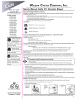
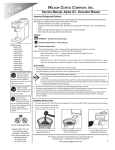
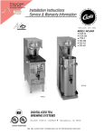
FIND OUT MORE
ON THE WEB.
W ILBUR CURTIS COMP
ANY, I NC.
OMPANY
WILBURCURTIS.COM
Alpha DS Decanter Brewer Instructions
Models Included
◆ ALPHA-1DS
◆ ALPHA-2DS
◆ ALPHA-3DS
◆ ALPHA-3DSR
◆ ALPHA-3DSL
◆ ALPHA-5DSR
◆ ALPHA-5DSL
◆ ALPHA-5DS
Important Safeguards/Conventions
This appliance is designed for commercial use. Any servicing other than cleaning and maintenance should be performed by an
authorized Wilbur Curtis service center.
• Do NOT immerse the unit in water or any other liquid
• To reduce the risk of fire or electric shock, do NOT open top or rear panel. No user serviceable parts inside. Repair should
be done only by authorized service personnel.
• Keep hands and other items away from hot parts of unit during operation.
• Never clean with scouring powders, bleach or harsh implements.
Conventions
WARNINGS – To help aavoid
void personal injur
injuryy
WARNING HOT LIQUID,
Scalding may occur.
Avoid splashing.
CAUTION: Please use
this setup procedure
before attempting to use
this brewer. Failure to follow the
instructions can result in injury or
the voiding of the warranty.
CAUTION: DO NOT
connect this brewer to
hot water. The inlet valve
is not rated for hot water.
Important Notes/Cautions – from the factor
factoryy
Sanita
tion Requirements
Sanitation
Your Curtis ADS System is FFactor
actor
actoryy Pre-Set and Read
Readyy to Go… Right from the Carton.
Following are the Factory Settings for your ALPHA™ DS Coffee Brewing Systems:
ture = 200°F
• Brew Tempera
emperature
• Brew Volume = Set to dispensing vessel requirements (60 oz)
• Warmer Setting on HIGH with Quality Timer OFF
Generally there will never be a reason to change your ADS programming. However, should you need to make slight adjustments to
meet your brewing needs, programming instructions are provided later in this manual.
System Requirements:
• Water Source 20 – 90 PSI (Minimum Flow Rate of 1 GPM)
• Electrical: See attached schematic for standard model or visit www.wilburcurtis.com for your model.
Equipment to be installed to comply with applicable federal, state, or local plumbing/electrical codes having jurisdiction.
SETUP STEPS
The unit should be level (left to right and front to back), located on a solid counter top. Connect a water line from the water filter to the
brewer. NOTE: Some type of water filtration device must be used to maintain a trouble-free operation. (In areas with extremely hard
water, we suggest that a sedimentary and taste & odor filter be installed.) This will prolong the life of your brewing system and
enhance coffee quality.
The National Sanitation Foundation requires the following water connection:
1. A quick disconnect or additional coiled tubing (at least 2x the depth of the unit) so that the machine can be moved for
cleaning underneath.
2. In some areas an approved backflow prevention device may be required between the brewer and the water supply.
WARNING TO AVOID
SCALDING, Do not
remove brewcone whil
brew light is flashing.
C
1. A 3/8” NPT x 1/4” Flare elbow has been supplied for water line connection. Use tubing sized sufficiently to provide a minimum of
1.0 GPM.
2. Connect the unit to an appropriate electrical power circuit.
3. Turn on the toggle (STANDBY/ON) switch behind the unit. The heating tank will start to fill. When the water level in the tank rises
to the correct volume, the heating elements will energize automatically. With ADS Systems there is no danger of element burnout
caused by an empty tank.
4. The heating tank will require 20 to 30 minutes to reach operating temperature (200°F) as indicated by the READY-TO-BREW
indicator.
5. Prior to brewing, dispense 12 ounces of hot water through the hot water faucet.
6. Brew a cycle of at least 12 ounces, to purge the water lines of any air that may be trapped after filling.
BREWING INSTR
UCTIONS
INSTRUCTIONS
1.
2.
3.
4.
Brewer should be ON (Confirm at rear toggle switch, then press ON/OFF button). Ready-to-Brew light should be ON.
Place empty DB-12 Decanter (not included) on warmer.
Place filter in Brewcone.
Pour ground
5. Position
6. Press Brew
coffee into
brewcone into
button.
brewcone.
brew rails.
ISO 9001 REGISTERED
WILBUR CURTIS COMPANY
Montebello, CA 90640
FOR THE LATEST SPECIFICATIONS AND INFORMATION GO TO
WWW.WILBURCURTIS.COM
1
STEPS TO
PROGRAMMING
PROGRAMMING ONLY REQUIRED IF FACTORY SETTINGS MUST BE CHANGED
Changing the ADS™ System Program
WARNING These steps involve
IMPORTANT – Before entering the program mode, allow the unit to reach brewing temperature, then press the BREW
working with hot water. Scalding
button to dispense at least 12 ounces of water. This is to clear any air that may be trapped within the water lines.
may occur if care is not taken
NOTE: For ALL functions you must first enter the programming mode.
against spilling.
Brew Temperature – Factory Pre-Set to 200°F
Function to set brew temperature, 170° to 204°F. Brew temperature will be indicated by READY-TO-BREW light blinking.
CONFIRM/RESET BREW TEMPERATURE - Factory Preset to 200º
ENTER THE PROGRAMMING MODE #1:
Press
for two seconds, then RELEASE.
ENTERING THE PROGRAM MODE #1
Turn OFF the power from the Control Panel by pressing
.
READY TO BREW
Press and HOLD
and press and RELEASE
.
will start blinking. Each blink equals 2º F, starting at 170º.
To change Temperature, press and HOLD
.
.
Continue HOLDING
until
READY TO BREW
starts blinking; RELEASE.
READY TO BREW will start QUICK flashing. Each QUICK flash equals 2º F.
After reaching 204º, temperature starts over at 170º.
RELEASE
when the desired temperature is reached.
To set and exit, press
.
BREW VOLUME - Factory Preset to Brewer Requirements
CHANGE BREW VOLUME
ENTER THE PROGRAMMING MODE #1
Press and HOLD
until hot water starts running from sprayhead; then RELEASE.
When desired volume is reached, press
To set and exit, press
again to stop flow.
.
BREW CYCLE COUNTER
TO ACCESS BREW CYCLE COUNTER
ENTER THE PROGRAM MODE #2
Turn OFF the power from the Control Panel by pressing
Press and HOLD
and press and RELEASE
.
ENTER THE PROGRAMMING MODE #2:
.
READY TO BREW
Continue HOLDING
until
READY TO BREW
STOPS blinking; RELEASE.
will now start a pattern of LONG and SHORT blinks.
This pattern identifies the number of brew cycles. SHORT blinks indicate the brew number from one [1] to nine [9].
LONG blinks separate the 1’s, 10’s, 1,000’s and 10,000’s.
LOW TEMPERATURE BREW LOCKOUT (DELTA) – Factory Preset to Delta 3
ENTER THE PROGRAM MODE #3
Turn OFF the power from the Control Panel by pressing
Press and HOLD
Continue HOLDING
RELEASE.
and press and RELEASE
until
READY TO BREW
.
.
stops blinking and remains on;
ENTER THE PROGRAMMING MODE #3
This mode will give you a choice of minimum brew temperatures.
Delta 1 allows you to brew within 5 degrees from set temperature. This provides for consistent brew
temperature and consistent water density. If Delta 1 is used, run one half decanter first, cancel and
discard water. Enter program mode #1 and change brew volume to 1/2” below collar of decanter (one
small finger width).
Delta 2 allows you to brew within 15 degrees from set temperature. If Delta 2 is used, run ½ of a decanter
first, cancel and discard water. Enter program mode #1 and change brew volume to 3/4” below collar
of decanter (between one and two small finger widths).
Delta 3 (this is factory setting) will allow you to brew at any temperature. Back to back brewing is only
possible in this mode. If Delta 3 is used, run one half decanter first, cancel and discard water.
Enter program mode #1 and change brew volume to 1” below collar of decanter (two small finger
widths). The brew cone must be empty without a filter. This will ensure proper operation at all brew
rates.
Press and HOLD
until
gives off one quic flash, then release
READY TO BREW
. You have now added a blink to
your blining light pattern.
WARMERS
By pressing and holding the
again, you add another blink.
Adjusting the Tempera
ture
emperature
NOTE: If Main Power is
turned OFF or Rear Toggle
Switch is switched to
STANDBY, the Warmer Quality Timer
must be re-programmed.
ALPHA Warmers feature two temperature settings -- HIGH and LOW (unit must be ON at the control panel). From the Warmer ON position. Press and hold the warmer button
for five seconds and the temperature will be set to LOW. LOW temperature is indicated by the “dimming” of the warmer indicator light above the Warmer Button. An
additional press of the Warmer Button will turn the warmer OFF. To return the warmer to HIGH (warmer should be ON), press and hold the warmer button for five seconds then
warmer will come on in the HIGH setting.
When the system is turned off at the ON/OFF button, it will remember the last warmer setting. Additionally, the ALPHA automatically turns the brew warmer on when the
BREW button is pressed.
Quality Timer – FFactor
actor
actoryy Set to DISABLED
ALPHA Systems feature a Quality Timer which will cause the warmer light to blink advising you coffee should be replaced. The Quality Timer can be set from DISABLED (zero)
to 50 minutes in 5 min intervals.
To set, follow these instructions:
WARMER QUALITY TIMER
PROGRAM WARMERS
Unit must be ON at the control panel.
Turn OFF the warmer at the the Control Panel by pressing one of the warmer
switches:
(Indiator light OFF).
To Determine Warmer Setting and Change Time for ALPHA Systems:
Press and HOLD
until the indicator light turns ON then OFF; release.
The light will start blinking. Count the blinks. Each blink = 5 minutes (maximum 50 minutes).
At the end of the cycle, press and HOLD
until the light begins quick flashing. The cycle will start over after 11
flashes (11 flashes is the DISABLED position).
2
When the desired time is reached, RELEASE
To set and exit, press
.
.
PARTS
DIAGRAMS
Illustrated Parts List (Alpha 3DS Model Shown)
Item
1
lA
2
2A
3
3A
4
5
5A
6
6A
7
7A
8
8A
9
10
11
12
13
14
14A
15
15A
16
17
18
19
20
21
21A
22
23
23A
23B
25
26
27
28
Part No.
WC-3621
WC-3316
WC-6812
WC-8567
WC-8578
WC-6218R
WC-2977
WC-102
WC-103
WC-8548
WC-8576
WC-826
WC-856
WC-889
WC-860
WC-2401
WC-5970
WC-8556
WC-8529
WC-1809
WC-2936
WC-2942
WC-753
WC-712
WC-5310
WC-5851
WC-5502-01
WC-1438
WC-5231
WC-917
WC-922
WC-522
WC-6266
WC-6265
WC-6267
WC-3765
WC-3763
WC-8591
CR -10
Description
BREWCONE, 7 1/8” BLK
BREWCONE W/BASKET, COMPLETE OPTIONAL
TOP WARMER ASSY 120V (ALP-3DS/DD/5DSL/DDL/DSR/1ODD/DS)
TOP WARMER ASSY 220V (ALP-3DS/DD/5DSL/DDL/DSR/1ODS)
WARMER ASSY, 120V ALPHA DD/DS
KIT, WARMER ASSY, 220V
FITTING, SPRAYHEAD PLT’D
SWITCH, TOGGLE SPST 25A 125/25OVAC RESISTIVE
SWITCH, TOGGLE DPST 25A 125/25OVAC RESISTIVE
KIT, MEMBRANE PLATE & BOARD ASSY, 120/220V ALPHA 3/5DSL/R
KIT, MEMBRANE PLATE & BOARD ASSY, 220V ALPHA 3/5DSL/R
VALVE, INLET 1.0 GPM 120V
VALVE, INLET 1.0 GPM 220V
VALVE, LIQUID DISPENSING LEFT 12OVAC 12W 12 IN WC HWR
VALVE, LIQUID DISPENSING LEFT 22OVAC 12W 12 IN WC HWR
ELBOW, 1/4 x 3/8 FLARE
COVER, BACK CTR WRAP ALPHA DS
HEAT SINK ASSEMBLY DV ALPHDS D5OOAP TCTD/PTTD
LEG, SCREW BUMPER (3/8”)
FAUCET, HOT WATER
SPRAYHEAD, RED .131 DIA
SPRAYHEAD, GREY .219 DIA
CONTROL BOARD, ALPHA DS 120/220 STD
CONTROL BOARD, 220V STRAIGHT
TUBING, 5/16 ID SILICONE GEN USE
LID, HEATING TANK
PROBE, WATER LEVEL CONTROL
SENSOR, TEMPERATURE
COMPOUND, SILICONE 5 OZ TUBE
HEATING ELEMENT, 1450W 120V
HEATING ELEMENT, 220V 3500W
THERMOSTAT, RESET
HEATING TANK COMPLETE, 120V OR 220V
HEATING TANK COMPLETE, 120/220V (DUAL VOLTAGE)
HEATING TANK, COMPLETE, 220V
KIT, VALVE REPAIR (USE WITH WC-826, WATER INLET VALVE)
KIT, VALVE REPAIR (USE WITH WC-889, DUMP VALVE)
CAPACITOR, X2 USED ON ALL ADS
FILTER PAPER, 12 CUP
ITEMS SPECIFIC TO ALPHA 1DS, 2DS,
3DSR, 3DSL, 5DSR & 5DSL
Item
29
30
32
32A
33
33A
34
34A
35
Part No.
WC-5450
WC-58058
WC-61107
WC-58019
WC-8574
WC-8575
WC-8572
WC-8573
WC-129
Description
COVER, TOP ALPHA 1DS, 3DSR & 3DSL
COVER, BOTTOM ALPHA 3DSR & 3DSL, 5DSR & 5DSL
COVER, TOP ALPHA 2DS
TOP COVER ASSY, ALPHA 2DS
PIGGYBACK ASSY, ALP-2DS 120/220V
PIGGYBACK ASSY, ALP-2DS 220V
PIGGYBACK ASSY, ALP-1DS 120/220V (NOT SHOWN)
PIGGYBACK ASSY, ALP-1DS 220V (NOT SHOWN)
SWITCH, WARMER RED ALPHA 5DS, 5DSR & 5DSL (NOT SHOWN)
3
ELECTRICAL
SCHEMA
TIC
SCHEMATIC
WARRANTY
We hereby certify that the products manufactured by the Wilbur Curtis Company, Inc., are, to thebest of our knowledge, free from all defects and faulty workmanship.
The following warranties and conditions are applicable:
• 90 Days for Labor and 1 Year Parts from Date of Purchase from Factory: This warranty covers all electrical parts, fittings and tubing.
• 40 Months or 40, 000 Pounds of Coffee on a set of Grinding Burrs. (ADS Grinders)
• 2 Years from Date of Purchase: This warranty covers electronic control boards and leaking or pitting of a stainless steel body of a Brewer or Urn.
• 90 Days from Date of Purchase: On replacement parts that have been installed on out of warranty equipment
All in-warranty service calls must have prior authorization from the manufacturer. For an RMA (Return Merchandise Authorization) number, call the Technical Service Department at 1-800-995-0417. The Wilbur Curtis
Company will allow up to 100 miles, round trip, per in-warranty service call.
CONDITIONS & EXCEPTIONS
The warranty covers original equipment at time of purchase only. The Wilbur Curtis Company, Inc., assumes no responsibility for substitute replacement parts installed on Curtis equipment that have not been purchased
from the Wilbur Curtis Company. Inc The Wilbur Curtis Company will not accept any responsibility if the following conditions are not met. The warranty does not cover and is void under these circumstances:
1) Improper operation of equipment. The equipment must be used for its designed and intended purpose and function.
2) Improper installation of equipment. This equipment must be installed by a professional, certified technician and must comply with all local electrical, mechanical and plumbing codes.
3) Wilbur Curtis Company will not be responsible for the operation of equipment at other than the stated voltages on the serial plate.
4) Abuse or neglect (including failure to periodically clean or remove lime accumulations). Manufacturer is not responsible for variation in equipment operation due to excessive lime or local water
conditions.
5) Replacement of items subject to normal use and wear. This shall include, but is not limited to, light bulbs, shear disks, “0” rings, gaskets, canister assemblies. whipper chambers and plates, mixing
bowls, agitation assemblies and whipper propellers.
6) Any faults resulting from inadequate water supply. This includes, but is not limited to, excessive or low water pressure, and inadequate or fluctuating water flow rate.
7) All repairs and/or replacements are subject to our decision that the workmanship or parts were faulty and the defects showed up under normal use.
8) All labor shall be performed during regular working hours. Overtime charges are the responsibility of the owner.
9) Charges incurred by delays, waiting time, or operating restrictions that hinder the service technician’s ability to perform service is the responsibility of the owner of the equipment.
This includes institutional and correctional facilities.
10) All claims under this warranty must be submitted to the Wilbur Curtis Company Technical Service Department before return of the unit to the factory.
11) All equipment returned to us must be repackaged properly in the original carton. No units will be accepted if they are damaged in transit due to improper packaging.
12) Damaged in transit.
13) The resetting of safety thermostats and circuit breakers, programming and temperature adjustments are the responsibility of the equipment owner.
NO UNITS OR PARTS WILL BE ACCEPTED WITHOUT A RETURN MERCHANDISE AUTHORIZATION (RMA). RMA NUMBER MUST BE MARKED ON THE CARTON OR SHIPPING LABEL.
All in-warranty service calls must be performed by an authorized service center, where service is available. Call the factory for location near you.
WILBUR CURTIS CO., INC.
6913 Acco St., Montebello, CA 90640-5403 USA
Phone: 800/421-6150
Fax: 323-837-2410
Technical Service Phone: 800/995-0417 (M-F 5:30A - 4:00P PST)
Web Site: www.wilburcurtis.com
4
10/2/01.13.0 . edr 3132 Rev NC
E-Mail: [email protected]
FOR THE LATEST SPECIFICATION INFORMATION GO TO WWW.WILBURCURTIS.COM
Printed in U.S.A.
8/01
F-3142-S Rev NC