1
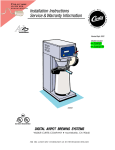
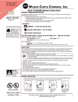
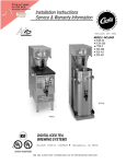
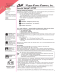
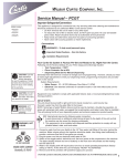
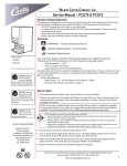
FIND OUT MORE
ON THE WEB.
WILBURCURTIS.COM
Installation Instructions
Service & Warranty Information
Revised Aug. 2002
Models Included
PC-3GT
PC-4GT
PC-5GT
PC-4GT
DRAFT
COPY
CONCEPT
SERIES
Not Released. This Version Exists as File No.
I:\DIAGRAMS\FRANK\FX-134.p65
INSTANT
CAPPUCCINO MACHINE
WILBUR CURTIS COMPANY
•
Montebello, CA 90640
C
ISO 9001 REGISTERED
FOR THE LATEST SPEC INFORMATION GO TO WWW.WILBURCURTIS.COM
F IND
OUT MORE
ON THE WEB
WWW.WILBURCURTIS.COM
W ILBUR CURTIS COMP
ANY, I NC.
OMPANY
Primo Cappuccino System Instructions
Important Safeguards/Conventions
Models Included
PC-3GT
PC-4GT
PC-5GT
This appliance is designed for commercial use. Any servicing other than cleaning and maintenance should be performed by an
authorized Wilbur Curtis service center.
• Do NOT immerse the unit in water or any other liquid
• To reduce the risk of fire or electric shock, do NOT open top panel. No user serviceable parts inside. Repair should be done
only by authorized service personnel.
• Keep hands and other items away from hot parts of unit during operation.
• Never clean with scouring powders or harsh implements.
Conventions
WARNING HOT
LIQUID, Scalding may
occur. Avoid splashing.
WARNINGS – To help aavoid
void personal injur
injuryy
Important Notes/Cautions – from the factor
factoryy
Sanita
tion Requirements
Sanitation
CAUTION: Please use
this setup procedure
before attempting to use
this appliance. Failure to follow the
instructions can result in injury or
the voiding of the warranty.
CAUTION: DO NOT
connect this unit to hot
water. The inlet valve is
not rated for hot water.
Your Curtis ADS System is FFactor
actor
actoryy Pre-Set and Read
Readyy to Go… Right from the Carton.
Following are the Factory Settings for your Primo Cappuccino Beverage System:
ture = 190°F
• Tank Tempera
emperature
• Flavor Controls= Set at 60%
• Dispensing Mode Set for Manual Dispensing
Generally there will never be a reason to change your ADS programming. However, should you need to make slight adjustments to
meet your brewing needs, programming instructions are provided later in this manual.
System Requirements:
• Water Source 20 – 90 PSI (Minimum Flow Rate of 1 GPM)
• Electrical: See attached schematic for standard model or visit www.wilburcurtis.com for your model.
Equipment to be installed to comply with applicable federal, state, or local plumbing/electrical codes having jurisdiction.
SETUP STEPS
The unit should be level (left to right and front to back), located on a solid counter top. Connect a water line from the water filter to the
brewer. NOTE: Some type of water filtration device must be used to maintain a trouble-free operation. (In areas with extremely hard
water, we suggest that a sedimentary and taste & odor filter be installed.) This will prolong the life of your brewing system and
enhance coffee quality.
The National Sanitation Foundation requires the following water connection:
1. A quick disconnect or additional coiled tubing (at least 2x the depth of the unit) so that the machine can be moved for
cleaning underneath.
2. In some areas an approved backflow prevention device may be required between the brewer and the water supply.
1. Connect a water line from your facility to the 1/4” flare water inlet fitting of the valve, behind the machine. Water volume
going to the machine should be stable. Use tubing sized sufficiently to provide a minimum flow rate of one gallon per minute.
2. Plug the power cord into an electrical outlet rated at 20A.
3. Switch on the CONTROL switch that runs power to the components in the machine. The lights (display window & row of
buttons) on the front door will activate and the heating tank will start to fill.
4. Once the water level has risen and covered the heating element, turn on the power to the heating element at the HEATING
ELEMENT switch behind the unit.
5. Water in the heating tank will require about 30 minutes to reach operating temperature (factory setting of 190°F). At this
time the READY light will come on.
6. Remove and fill the canisters with powdered cappuccino mixes.
WARNING, HOT
LIQUID
OPERA
TION INSTR
UCTIONS
OPERATION
INSTRUCTIONS
1. Choose a flavor. Place your cup under the spout beneath the desired flavor.
2. Push the dispensing button for this flavor.
3. Allow the Primo Cappuccino unit time to completely dispense the product.
C
ISO 9001 REGISTERED
WILBUR CURTIS COMPANY
Montebello, CA 90640
FILL CANISTERS DAIL
DAILYY
1. Open the front door to access canisters.
2. The canisters must be removed from the unit for filling. The canisters hold five pounds of product. Larger canisters hold 10
pounds each.
3. Reposition the canisters on the machine, aligning the gear socket with the motor shaft.
FOR THE LATEST SPECIFICATIONS AND INFORMATION GO TO
WWW.WILBURCURTIS.COM
1
Steps to Programming
Your Curtis ADS System is FFactor
actor
actoryy Pre-Set for
Optimum Performance. Usually this Does Not
Change.
Program Menus
Select
Entering the Programing Menus
Press and hold STOP/WASH for five [5] seconds. Display will
read Program Menus
Menus,(See Illustration).
Manual Dispense
Press
or > to go to Manual Dispense Select
Select.
Press
to go to Manual Dispense Select Station
Station.
Choose the station and press, the display will read Saving
PROGRAMMING SELECTIONS
Complete! To select another station for manual dispense,
press
to go to Manual Dispense Select Station or press > to continue to the next menu.
Dispense By Time
The next screen is Dispense By Time < Select >
>. Press
to select a station. Select the station and the screen will read To Begin Push Start
Start.
inish Push Stop. When Push is pressed, time will be saved
Press desired dispense button. Hot water will start to dispense and screen will display To FFinish
and you will exit back to Dispense by Time screen. Continue with additional selections or press > to continue to the next menu.
Tempera
ture (F
actor
0 °F)
F)
emperature
(Factor
actoryy set 19
190
Press and screen will show Tank Temperature. Temperature is programmable from 170°F to 204°F in 2-degree increments. Press < or > to go up or
down in degrees. Select desired temperature and then to set. Press > to continue to the next menu.
Powder % Ratio
Press
and the screen will display Powder % Ratio Select Station
Station. Press desired station. Powder ratio is programmable from 0% (Hot Water) to
100%, in 5% increments. Press < or > to increase or decrease ratio and then press to set. Press > to continue to the next menu.
Service Call (Phone number)
Press to display number and press change number or > to move places and EX to exit when complete This number will be displayed during a
Heating system SENSOR ERROR or a WATER ERROR. Press > to continue to the next menu.
Banner Name
Press
to display letters, press to change letters or > to move places and EX to exit when complete.
This feature allows up to 14 letters to be programmed for company name or regional name. Programming all blanks disables Banner Name. If programmed, Banner Name is displayed every 5 sec. on and off. Press > to continue to the next menu.
Model Select
Press
Exit
Press
to select, < or > to select desired model (PC-1, 2, 3, 4, 5) . Press
to set and exit program mode.
to select, exits program mode and returns unit to operation.
Illustrated Parts List
2
Nº
1
2
2A
3
3A
4
4A
5
6
7
8
8A
9
9A
10
10A
10B
11
11A
11B
12
Part N
Description
Nº
WC-7348
PANEL, LEFT SIDE PCGTs
CA-1097
DOOR,/WINDOW SUPPORT ASSY, PCGT-3
CA-1103
DOOR/WINDOW SUPPORT ASSY, PCGT-4/5
CA-1101
WINDOW, FRONT CLEAR PCGT-3
CA-1107
WINDOW, FRONT CLEAR PCGT-4/5
CA-1109-01 FILM, CURTIS LOGO PCGT-3
CA-1110-01 FILM, CURTIS LOGO PCGT-4/5
CA-1117
LAMP COMPLETE, W/5K BULB
WC- 778
CONTROL MODULE, PCGT-1/2/3/4/5 120V
WC-39349
LABEL ASSY, UCM & DOOR PCGT-3
WC-39350-01 LABEL, UCM PANEL PCGT4 CURTIS
WC-39351-01 LABEL, UCM PANEL PCGT5 CURTIS
WC-39350-04 MEMBRANE CNTRL PNL CURTIS PCGT4
WC-39351-04 MEMBRANE CNTRL PNL CURTIS PCGT5
CA-1098
COVER, ALCOVE PLASTIC PCGT-3
CA-1104
COVER, ALCOVE PLASTIC PCGT-4/5
CA-1115
COVER, ALCOVE PLASTIC PCGT-5
CA-1100
COVER, DRIP TRAY PLASTIC PCGT-3
CA-1106
COVER, DRIP TRAY PLASTIC PCGT-4
CA-1114
COVER, DRIP TRAY PLASTIC PCGT-5
WC-5661
LID ASSY, TANK
Nº
13
14
15
16
17
18
19
19A
20
20A
21
21A
21B
22
23
24
25
26
27
28
28A
Part N
Nº
WC-5502-01
WC-3734
WC- 904
WC-1438-101
WC- 523
WC- 102
WC-68131
WC-68130
CA-1099
CA-1105
CA-1112-05
CA-1113-05R
CA-1113-05L
CA-1011-05
CA-1065-03
CA-1026-03
CA-1005-03
CA-1009-03
CA-1037-8
CA-1002
WC-5664-05
Description
PROBE ASSY, WATER LEVEL
KIT, RPL DUMP VALVE FOR WC-880E
HEATING ELEMENT, 1.6KW W/JAMNUTS
SENSOR, TEMERATURE TANK
THERMOSTAT, MNL RESET 120/240V 25A
SWITCH, TOGGLE NON LIT 25A 120/240V
SCREEN, DRIP TRAY PCGT-3
SCREEN DRIP TRAY PCGT-4/5
DRIP TRAY, PLASTIC PCGT-3
DRIP TRAY, PLASTIC PCGT-4/5
CANISTER ASSY, 5LB PCGTs
CANISTER ASSY, 10LB RIGHT PCGTs
CANISTER ASSY, 10LB LEFT PCGTs
FITTING, BULKHEAD WATER
BUSHING, DISCHARGE
ELBOW, PC/CK/HC
STEAM TRAP
BOWL, MIXING
TUBE, EXTENSION .714 OD x3.4 YELLOW
LID, CANISTER, 5LB ROUNDED CORNERS
LID, CANISTER, 10LB PCGT’s
Nº
29
30
31
32
33
34
35
36
37
38
39
40
41
42
43
44
45
46
47
48
49
Part N
Nº
CA-1047
CA-1051-03
WC-2626-03
CA-1012-05
CA-1024-05
WC-43791
CA-1010-05
CA-1008-05
CA-1006-05
CA-1013
CA-1036
WC- 826
CA-1014-05
CA-1030-05
WC-3765
WC-39350-02
WC-39203
WC-8591
WC-7349
WC- 780
WC-8556
Description
AUGER, WIRE PCs & PCGTs
SOCKET, GEAR
BUSHING, AUGER PC/CK/HC
MOTOR, WHIPPER
PILLAR, LOCATION BLACK (NOT SHOWN)
RING, MOTOR SHAFT (NOT SHOWN)
PLATE, WHIPPER CHAMBER OPEN W/SEAL
PROPELLER, WHIPPER PCGTs
WHIPPER CHAMBER
GEAR MOTOR
GEAR, PLASTIC USE ON CA-1013
VALVE, INLET
FAN, EXTRACT 120V 29 CFM 115V 60HZ
HOSE AIR (NOT SHOWN)
KIT, INLET VALVE REPAIR USE ON WC-826
LABEL, PANEL FLAVOR CURTIS
LABEL, SERVICE & PROG (NOT SHOWN)
CAPACITOR, X2 ALL ADS MODELS
PANEL, RIGHT SIDE PCGTs
CONTROL, POWER MODULE PCGT 120V
HEAT SINK ASSEMBLY (NOT SHOWN)
Illustrated Parts List
12
13
14
1
43
40
15
16
17
D
D
18
46
35
36
2
37
C
B
3
4
48
5
38
41
6
A
7
8
9
10
39
B
20
11
19
Shaft seals should be
replaced with the groved
side facing outward.
Place a dab of food
grade lubricant in the
rear hole of the seal,
as shown at below.
47
44
28
21
22
29
30
31
23
24
25
26
Before mounting a whipper
plate, place a dab of food
grade lubricant in the rear
hole of the seal.
27
C
A
32
33
34
3
Electrical
Diagram
WARRANTY
We hereby certify that the products manufactured by the Wilbur Curtis Company, Inc., are, to thebest of our knowledge, free from all defects and faulty workmanship.
The following warranties and conditions are applicable:
• 90 Days for Labor and 1 Year Parts from Date of Purchase from Factory: This warranty covers all electrical parts, fittings and tubing.
• 40 Months or 40, 000 Pounds of Coffee on a set of Grinding Burrs. (ADS Grinders)
• 2 Years from Date of Purchase: This warranty covers electronic control boards and leaking or pitting of a stainless steel body of a Brewer or Urn.
• 90 Days from Date of Purchase: On replacement parts that have been installed on out of warranty equipment
All in-warranty service calls must have prior authorization from the manufacturer. For an RMA (Return Merchandise Authorization) number, call the Technical Service Department at 1-800-995-0417. The Wilbur
Curtis Company will allow up to 100 miles, round trip, per in-warranty service call.
CONDITIONS & EXCEPTIONS
The warranty covers original equipment at time of purchase only. The Wilbur Curtis Company, Inc., assumes no responsibility for substitute replacement parts installed on Curtis equipment that have not been
purchased from the Wilbur Curtis Company. Inc The Wilbur Curtis Company will not accept any responsibility if the following conditions are not met. The warranty does not cover and is void under these
circumstances:
1) Improper operation of equipment. The equipment must be used for its designed and intended purpose and function.
2) Improper installation of equipment. This equipment must be installed by a professional, certified technician and must comply with all local electrical, mechanical and plumbing codes.
3) Wilbur Curtis Company will not be responsible for the operation of equipment at other than the stated voltages on the serial plate.
4) Abuse or neglect (including failure to periodically clean or remove lime accumulations). Manufacturer is not responsible for variation in equipment operation due to excessive lime or local
water conditions.
5) Replacement of items subject to normal use and wear. This shall include, but is not limited to, light bulbs, shear disks, “0” rings, gaskets, canister assemblies. whipper chambers and
plates, mixing bowls, agitation assemblies and whipper propellers.
6) Any faults resulting from inadequate water supply. This includes, but is not limited to, excessive or low water pressure, and inadequate or fluctuating water flow rate.
7) All repairs and/or replacements are subject to our decision that the workmanship or parts were faulty and the defects showed up under normal use.
8) All labor shall be performed during regular working hours. Overtime charges are the responsibility of the owner.
9) Charges incurred by delays, waiting time, or operating restrictions that hinder the service technician’s ability to perform service is the responsibility of the owner of the equipment.
This includes institutional and correctional facilities.
10) All claims under this warranty must be submitted to the Wilbur Curtis Company Technical Service Department before return of the unit to the factory.
11) All equipment returned to us must be repackaged properly in the original carton. No units will be accepted if they are damaged in transit due to improper packaging.
12) Damaged in transit.
13) The resetting of safety thermostats and circuit breakers, programming and temperature adjustments are the responsibility of the equipment owner.
NO UNITS OR PARTS WILL BE ACCEPTED WITHOUT A RETURN MERCHANDISE AUTHORIZATION (RMA). RMA NUMBER MUST BE MARKED ON THE CARTON OR SHIPPING LABEL.
All in-warranty service calls must be performed by an authorized service center, where service is available. Call the factory for location near you.
4
8/7/02. 12.0 . ECN 5094 rev A
WILBUR CURTIS CO., INC.
6913 Acco St., Montebello, CA 90640-5403 USA
Phone: 800/421-6150
Fax: 323-837-2410
Technical Service Phone: 800/995-0417 (M-F 5:30A - 4:00P PST)
Web Site: www.wilburcurtis.com
E-Mail: [email protected]
FOR THE LATEST SPECIFICATION INFORMATION GO TO WWW.WILBURCURTIS.COM
Printed in U.S.A.
8/02
F-2079-S Rev A