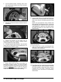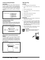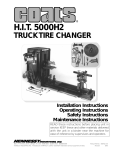
1
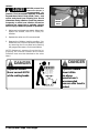
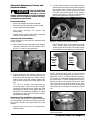
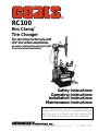
®
RC100
Rim Clamp®
Tire Changer
For servicing motorcycle and
ATV tire/wheel assemblies
as well as automotive and most light
truck tire/wheel assemblies
Safety Instructions
Operating Instructions
Installation Instructions
Maintenance Instructions
READ these instructions before placing unit in
service. KEEP these and other materials delivered
with the unit in a binder near the machine for
ease of reference by supervisors and operators.
1601 J. P. Hennessy Drive, LaVergne, TN USA 37086-3565 615/641-7533 800/688-6359
HENNESSY INDUSTRIES INC. Manufacturer of AMMCO®, COATS® and BADA® Automotive Service Equipment and Tools.
Manual Part No.: 8183186 00
Revision:
02/97
Table of Contents
Operator Protective Equipment
Definitions of Hazard Levels ................................1
Owner's Responsibility ........................................1
Principal Operating Parts .....................................2
Operating Instructions .........................................3
Bead Loosening and Demounting ................3
Mounting .........................................................6
Inflation ..................................................................7
Bead Sealing ...................................................7
Bead Seating ...................................................8
Inflation ...........................................................8
Performance, Custom, and Aluminum Wheels ..9
Custom and Special Wheels ..............................12
Personal protective equipment helps make tire
changing safer. However, equipment does not take
the place of safe operating practices. Always wear
durable work clothing during tire service activity.
Shop aprons or shop coats may also be worn,
however loose fitting clothing should be avoided.
Tight fitting leather gloves are recommended to
protect operator’s hands when handling worn tires
and wheels. Sturdy leather work shoes with steel
toes and oil resistant soles should be used by tire
service personnel to help prevent injury in typical
shop activities. Eye protection is essential during
tire service activity. Safety glasses with side
shields, goggles, or face shields are acceptable.
Back belts provide support during lifting activities
and are also helpful in providing operator
protection. Consideration should also be given to
the use of hearing protection if tire service activity
is performed in an enclosed area, or if noise levels
are high.
Tube Type Tires ...................................................12
Stages of Inflation ...............................................13
Bead Seal ......................................................13
Bead Seat ......................................................13
Inflation .........................................................13
Mis-Matched Tires and Wheels .........................13
Maintenance Instructions ..................................14
Installation Instructions .....................................15
Critical Safety Instructions .................Back Cover
Failure to follow danger,
warning, and caution
instructions may lead to
serious personal injury or death to operator or
bystander or damage to property. Do not operate
this machine until you read and understand all
the dangers, warnings and cautions in this
manual. Download a copy of the manual from
our website at www.ammcoats.com, or for
further information, contact:
WARNING
Hennessy Industries, Inc.
1601 J.P. Hennessy Drive
LaVergne, TN 37086-3565
(615) 641-7533 or (800) 688-6359
www.ammcoats.com
For additonal tire, wheel, and/or inflation information
contact the following:
RUBBER MANUFACTURERS ASSOCIATION
1400 K Street N.W.
Washington, DC 20005
(202) 682-4800
www.rma.com
TIRE GUIDES, INC.
The Tire Information Center
1101-6 South Rogers Circle
Boca Raton, FL 33487-2795
(561) 997-9229
www.tireguides.com
Definitions of Hazard Levels
Identify the hazard levels used in this manual
with the following definitions and signal words:
DANGER
Watch for this symbol:
Owner's Responsibility
To maintain machine and user safety, the
responsibility of the owner is to read and
follow these instructions:
• Follow all installation instructions.
! DANGER
It Means: Immediate hazards which will result
in severe personal injury or death.
• Make sure installation conforms to all
applicable Local, State, and Federal
Codes, Rules, and Regulations; such as
State and Federal OSHA Regulations
and Electrical Codes.
WARNING
Watch for this symbol:
• Carefully check the unit for correct
initial function.
! WARNING
It Means: Hazards or unsafe practices which
could result in severe personal injury or death.
• Read and follow the safety instructions.
Keep them readily available for
machine operators.
• Make certain all operators are properly
trained, know how to safely and
correctly operate the unit, and are
properly supervised.
CAUTION
Watch for this symbol:
! CAUTION
It Means: Hazards or unsafe practices which
could result in minor personal injury or product
or property damage.
Watch for this symbol! It means BE ALERT!
Your safety, or the safety of others, is
involved!
• Allow unit operation only with all parts
in place and operating safely.
• Carefully inspect the unit on a regular
basis and perform all maintenance as
required.
• Service and maintain the unit only with
authorized or approved replacement
parts.
• Keep all instructions permanently with
the unit and all decals on the unit clean
and visible.
DANGER
Explosion Hazard
Never exceed 40
PSI while seating
beads.
DANGER
Explosion Hazard
Never inflate
tire above
manufacturer's
recommended
pressure after bead
is seated.
RC100 Rim Clamp Tire Changer • 1
Principal Operating Parts
Know Your Unit
Compare this illustration with the unit before
placing it into service. Maximum performance
and safety will be obtained only when all
persons using the unit are fully trained in its
parts and operation. Each user should learn the
function and location of all controls. Prevent
accidents and injuries by ensuring the unit is
properly installed, operated, and maintained.
11
2
✓
Do It Now
Now is a good time to fill out the warranty
registration card. This card must be mailed
within 30 days of purchase or the warranty
may be voided.
17
12
18
10
15
1
3
8
7
19
13
9
4
6
5
1 Tower — Support for horizontal arm and vertical
slides, also air storage tank.
2 Air Gauge — Registers tire pressure when air chuck
is attached to valve stem and inflation pedal is
released.
3 Inflation Pedal — Two position pedal that allows
inflation of tires through air hose and clip-on chuck.
14
16
11 Swing Arm Adjustment Knob — Adjusts swing
arm/vertical slide assembly for proper horizontal
positioning of mount/demount head.
12 Vertical Slide Locking Handle — Locks and unlocks
vertical slide and sets correct vertical position to
maintain head/wheel clearance.
13 Bead Lifting Tool — Used to lift and position tire
bead correctly on mount/demount head.
4
Clamp Control Pedal — Three position pedal that
opens and closes rim clamps.
5
Table Top Pedal — Three position pedal that
controls rotation of table top.
14 Bead Loosener Shoe — Pivoting shoe for loosening
tire beads.
15 Oil Check Dipstick — For transmission oil level.
6 Bead Loosener Pedal — Controls operation of bead
16 ATV Riser Plate — Adjusts to raise ATV wheels to
7 Table Top — Rotating chuck for tire changing.
17 Pressure Safety Valve — The high pressure safety
8 Motorcycle or ATV Clamp Adapter — Secures wheel
18 Release Valve — Allows the manual release of air
9 Lube Bottle — Dispenser for rubber lubricant.
19 Filter/Regulator/Lubricator — Filters and lubricates
loosener shoe.
to table top for tire changing.
10
Combination Mount/Demount Head — Mounts and
demounts tire from wheel.
2 • RC100 Rim Clamp Tire Changer
centerline of bead loosener..
valve is set to exhaust at pressures above 185 PSI.
pressure from tire.
air to machine, and adjusts air pressure to prevent
wheel damage.
Operating Instructions
The unit must be properly operated and properly
maintained to help avoid accidents that could
damage the unit and injure the operator or
bystanders. This section of the Operating
Instructions manual review basic operations and
use of controls. These instructions should be
reviewed with all employees before they are
allowed to work with the machine. Keep these
instructions near the machine for easy reference.
Bead Loosening and Demounting
This machine may
operate differently
from machines you
have previously operated. Practice with a
regular steel wheel and tire combination to
familiarize yourself with the machine's operation
and function.
! CAUTION
Remember to remove all weights from both
sides of the wheel. Weights left on back side of
wheel may cause the wheel to be clamped
unlevel. This may result in the combination
mount/demount head contacting the rim causing
scratches. On alloy wheels, always rotate the
wheel one turn after setting the head to insure
proper wheel chucking.
bolt together). See Figure 4 for more
information on the drop center.
REMEMBER: The clamps on the table top
may extend beyond the table top itself. To
avoid damaging the clamps, move them to
their full inward position before positioning a
tire for bead loosening.
NOTE: Use extra care in positioning the bead
loosener shoe on larger wheels/tires, and on
alloy wheels. Make sure the shoe rests next
to but not on the rim, and not on the tire
sidewall. The riser underneath the bead
loosener will help properly position ATV
wheels.
2. Pull the bead loosener shoe away from the
machine and roll wheel into position. The
valve stem should be in the 3 o'clock
position. Position the bead loosener shoe
against the tire next to, but not on, the rim.
Depress the bead loosener foot pedal to
actuate the shoe and loosen the bead. It may
be necessary to loosen the bead in multiple
locations around the tire (Figure 2).
NOTE: Always review nicks and scratches with
owners of expensive wheel and tire
combinations prior to servicing.
IMPORTANT: Review the performance wheel
section of this manual prior to servicing
performance tire/wheel combinations.
1. Deflate tire completely by removing the valve
core from the valve stem (Figure 1).
Motorcycle
ATV
Figure 2 - Position Tire and Bead Loosener Shoe
3. Turn wheel around and repeat loosening
procedure on the other side of the wheel.
This should be the long side of the drop
center.
TIP: It will be easier to clamp the wheel to the
table top if the lower bead is loosened last.
4. Apply tire manufacturer's approved rubber
lubricant liberally to entire circumference of
both tire beads after loosening.
Figure 1 - Remove Valve Core to Deflate Tire
NOTE: Loosening the beads on a fully
inflated tire is unsafe and causes excess
movement and friction against the bumper
pads and excessive wear on pivots. Deflate
the tire completely to prolong the life of your
machine.
ATV NOTE: It may be necessary on ATV
wheels to leave 5-10 PSI in some of these
wheels to facilitate bead loosening.
NOTE: Always loosen the bead on the
narrow side of the wheel's drop center first
(motocycle wheels may not have a narrow or
long side, and some ATV wheels may may
Motorcycle
ATV
Figure 3 - Apply Rubber Lubricant to Tire Beads
RC100 Rim Clamp Tire Changer • 3
5. Determine the mounting side of the wheel.
The mounting side is the narrow side of the
drop center. (Tire removed in Figure 4 for
clarity.)
8. The mount/demount head roller should be in
contact with the rim edge. Turn the swing
arm adjusting knob to move the head away
from the rim 1/8 to 1/4 inch.
Narrow Side
Drop Center
Long Side
Motorcycle
ATV
Figure 4 - Determining Mounting Side of Wheel
6. Place tire/wheel assembly on table top with
mounting side up (Figure 5). Use the clamp
control pedal to move the clamps inwards
(push pedal down) or outwards (toggle pedal
up). Clamp motorcycle and ATV wheels from
the outside (clamps push inwards against the
outside rim edge). Place rim flange into rear
clamp and slowly move the other clamps
inward until they contact the rim. Observe
closely to prevent tire/wheel damage.
Figure 7 - Adjust Swing Arm to Position Head Roller
9. Check head positioning. Mount/demount
head should be positioned with 1/8 to 3/16"
clearance between the top of the rim edge
and the bottom of the head, and 1/8 to 1/4
inch clearance between the rim edge and the
head. This clearance will be maintained as
long as the locking handle and adjustment
knob are not changed. The operator may
swing the arm out of the way and back into
place again without needing to reposition the
head (when changing a set of the same
wheels).
1/8" to 3/16"
Motorcycle
ATV
1/8" to 1/4"
Figure 8 - Proper Mount/Demount Head Position
Figure 5 - Place Tire/Wheel Assembly on Table Top
7. Move the swing arm into position. Pull the
locking handle forward to release the slide.
Push down on the top of the vertical slide to
move the demount head into contact with
the rim edge. Push the locking handle back to
lock the slide into place. As the slide is
locked, the mount/demount head will move
upward approximately 1/8 inch from the rim
edge.
Figure 6 - Position
Mount/Demount Tool
4 • RC100 Rim Clamp Tire Changer
IMPORTANT: The vertical tool clearance may
change with machine use and should be
inspected often. Failure to maintain the
proper clearance may result in damage to the
wheel rim and/or tire.
10. Insert the smooth curved end of the bead
lifting tool over the forward end of the
demount head and below the top bead of the
tire. Use your free hand to press down on the
tire opposite the head to help with tool
insertion (Figure 9).
14. Depress the table top pedal to rotate the
wheel. The demount head will guide the
bead up and over the edge of the wheel.
Continue rotation until lower bead is
demounted.
NOTE: With tube-type tires, demount the upper
bead and remove the tube before demounting
the lower bead.
Motorcycle
ATV
Figure 9 - Insert Bead Lifting Tool
11. Push the bead lifting tool down towards the
wheel to lift the tire bead up and over the
knob portion of the demount head. The tool
may be removed if desired (Figure 10).
Motorcycle
ATV
Figure 10 - Lift Bead Over Demount Head
NOTE: Table top rotation can be stopped at any
time by removing your foot from the pedal.
NOTE: Normal table top rotation for demounting
is clockwise. Depress the table top pedal to
rotate this direction. To rotate the table top
counterclockwise, lift the pedal up with your toe.
At times during the
mounting
and
d e m o u n t i n g
procedure, the bead lifting tool may encounter
resistance or come under load. Keep one hand
firmly on the tool to avoid possible tool
disconnect. Use the reversing feature to back
out or jam ups.
! CAUTION
✓
After successfully completing the
demount process, proceed to Mounting
(page 6).
12. Depress the table top pedal to rotate the
wheel clockwise. The demount head will
guide the upper bead up and over the edge
of the wheel.
NOTE: Push down on the tire across from the
demount head during table top rotation to
utilize the drop center area of the wheel. This
reduces the tensional force on the bead
during demount.
13. Lift and hold the tire at an angle so that the
lower bead is resting in the drop center
directly across from the demount head, and
is loose below the demount head (Figure 11).
Insert the smooth curved end of the bead
lifting tool down over the forward end of the
mount/demount tool and below the lower
bead. Lift the bead up and over the knob on
the demount head (Figure 11).
Motorcycle
Figure 11 - Demounting Lower Bead
ATV
Operator Protective Equipment
Always wear durable work clothing during tire
service activity. Shop aprons or shop coats may
also be worn, however, loose fitting clothing
should be avoided. Tight fitting leather gloves
are recommended to protect the operator's
hands when handling worn tires and wheels.
Sturdy leather work shoes with steel toes and
oil resistant soles should be used by tire service
personnel to help prevent injury in typical shop
activities. Eye protection is essential during tire
service activity. Safety glasses with side shields,
goggles, or face shields are acceptable. Back
belts provide support during lifting activities
and are also helpful in providing operator
protection.
RC100 Rim Clamp Tire Changer • 5
Mounting
This information must be read and followed
carefully to prevent accidents and injuries during
mounting.
4. Place tire over wheel and move swing arm
into position. Position the tire so that the
lower bead is above the rear extension of the
mount/demount head and below the front
knob (Figure 14).
Check tire and wheel
carefully
before
mounting. Make sure
the tire bead diameter and wheel diameter
match exactly. Consult the Rubber
Manufacturer's Association for approved rim
widths for tire sizes. Mis-matched tires and
wheels explode.
! WARNING
Never Mount a tire
and wheel handed to
you
by
anyone
without checking both tire and wheel for
damage and compatibility. Be extra cautious of
persons without knowledge of tire service. Keep
by-standers out of service area.
! CAUTION
Never
mount
a
damaged tire. Never
mount a tire on a
rusty or damaged wheel. Damaged tires and/or
wheels may explode.
! WARNING
If you damage the
tire bead during
mounting, STOP!,
remove the tire and mark it as damaged. Do not
mount a damaged tire.
! CAUTION
1. Inspect the wheel closely for damage. Clean
the wheel and remove any light corrosion or
rubber residue (Figure 12). Do not attempt to
service heavily corroded wheels.
Motorcycle
ATV
Figure 14 - Position Tire Against Mount/Demount Head
5. Depress table top pedal and rotate the wheel
to mount the lower bead. Use the drop
center of the wheel to reduce the tensional
force on the bead by pressing down on the
tire directly across from the mount
head.Rotate table top until lower bead is fully
mounted.
6. For top bead, rotate the table top until the
valve stem is directly across from the mount
head. Lift the upper bead up and over the
rear of the mount head. With your left hand
press down on the tire between the mount
head and the valve stem to hold the tire in
the drop center. Depress the table top pedal
and rotate the tire until the bead is mounted.
Continue to press down on the tire during
the remaining mounting process.
Do not force the tire
onto the rim. Bead
damage could result
making the tire unsafe and/or creating the risk
of injury.
! WARNING
Motorcycle
ATV
Figure 12 - Inspect and Clean the Wheel
2. Inspect tire for damage, paying close
attention to the beads. Verify size match
between tire and wheel (Figure 12).
3. Lubricate tire beads liberally with tire
manufacturer approved lubricant (Figure 13).
NOTE: If table top rotation stalls, reverse the
table top momentarily until the tire bead is again
loose on the wheel. Reposition the mount head,
make sure the bead is correctly positioned in the
drop center of the wheel, then attempt mounting
again.
NOTE: For low profile or stiff sidewall tires, it
may be advantageous to use the bead lifting tool
to initially hold the upper bead down in the drop
center, or use drop center tools as shown in
Figure 30, page 11.
NOTE: For tube type tires, mount the lower bead
first, move swing arm out, install the tube, and
then mount the upper bead.
✓
Figure 13 - Lubricate Beads
6 • RC100 Rim Clamp Tire Changer
When you have completed the
mounting process, proceed to Inflation,
page 7.
Inflation
Bead Seating
On the RC100, tire inflation is performed in two
steps: Bead Seat and Inflation. These steps are
explained in detail on page 13. Read the
explanation of each step and understand them
thoroughly before proceeding.
Operator
should
keep hands, arms,
and entire body
away from the tire during the remaining bead
seat and inflation procedures. Do not stand over
tire, as personal injury could result.
Check for proper
inflation
gauge
operation. Accurate
pressure readings are important to safe tire
inflation. Refer to the Operating Maintenance
section of this manual for instructions.
! CAUTION
If the rim has been
clamped from the
outside for tire
mounting, release the clamps, lift the tire, and
move the clamps to the center of the table top.
! CAUTION
! WARNING
NEVER increase air
pressure to exceed
40
PSI
when
attempting Bead Seat. If operator is unable to
obtain Bead Seat, something is wrong. Deflate
tire completely, inspect both the tire and wheel,
correct any problems found, relubricate both tire
beads, and reattempt Bead Seal and Bead Seat
procedures. Follow all safety instructions in this
manual and on machine.
! WARNING
Tire failure under
pressure
is
hazardous. This tire
changer is not intended to be a safety device to
contain exploding tires, tubes, wheels, or bead
sealing equipment. Inspect tire and wheel
carefully for match, wear, or defects before
mounting. Always use approved tire bead
lubricant during mounting and inflation.
1. Once tire pressure is indicated on the air
gauge (inflation pedal in position 1; foot
removed from pedal), continue to inject air
into the tire in short intervals. Check the
pressure frequently.
The inflation pedal, located at the rear of the left
side of the machine, controls the flow of air
through the inflation hose.
Tire beads should move outward and "pop"
into their bead seat position as pressure
inside the tire increases. If this does not
happen, a problem exists. Investigate
carefully.
! DANGER
NOTE: The clip-on chuck on the end of the hose
should always be an open style with all parts in
proper working order.
Tire Pressure
Tire Inflation
Position 1 - At Rest – With the inflation hose
attached to the tire valve and the pedal in this
position, the air gauge will register the air
pressure in the tire. Whenever your foot is
removed from the pedal, it will return to this
position.
Stand back during bead seat. Keep hands,
arms, and entire body away from tire during
this procedure.
Check tire pressure
frequently. Never
exceed 40 PSI while
seating beads. Once seated, never exceed tire
manufacturer's recommended air pressure. Tires
can explode, especially if they are inflated
beyond their limits. At all pressure levels when
inflating through the valve stem, keep hands,
arms, and entire body away from inflating tire.
An exploding tire, wheel, or bead sealing
equipment may propel upward and outward
with sufficient force to cause serious injury or
death to operator or bystander.
! WARNING
Position 2 - Tire Inflation – This is the first
activated position. With the inflation hose
attached to the tire valve and the pedal in this
position, line pressure is allowed to flow through
the valve and into the tire for inflation. Tire
pressure is not indicated on the gauge in this
position.
RC100 Rim Clamp Tire Changer • 7
Inflation
NEVER exceed tire
manufacturer's
recommended air
pressure. Tires can explode, especially if inflated
beyond these limits. Keep hands, arms, and
entire body back from inflating tire. Avoid
distraction during inflation. Check tire pressure
frequently to avoid over inflation. Excessive
pressure can cause tires to explode, causing
serious injury or death to operator or bystander.
! DANGER
Manual
Release
Valve
Figure 15 - Stand Back During Beat Seat and Inflation
1. Make sure both beads are seated. When both
beads are seated, the tire is ready for
inflation.
2. Replace the valve core if it was removed.
3. Depress the inflation pedal to position 2 to
inflate the tire. Check tire pressure frequently
by removing foot from pedal and checking
the gauge onthe tower. Avoid overinflation.
NOTE: Release air pressure from the tire by
pressing the manual release valve button
(inflation hose must be attached to the valve
stem).
DANGER
DANGER
Explosion Hazard
Explosion Hazard
Never exceed 40 PSI
while seating beads.
Never inflate
tire above
manufacturer's
recommended
pressure after bead is
seated.
8 • RC100 Rim Clamp Tire Changer
Automobile Performance, Custom, and
Aluminum Wheels
Only tire technicians
with experience and
training on custom
wheels should attempt to service expensive
custom alloy or aluminum wheels and highperformance low-profile tires.
! CAUTION
2. Pull the bead loosener shoe away from the
machine and roll the tire into position against
the bumper pad. Position the tire with the
valve stem in the 3 o'clock position (in direct
line with the bead loosener shoe). Always
loosen the bead on the narrow/mounting
side of the wheel first (Figures 4 and 17).
Pre-Operation Notes:
• Ensure all weights have been removed.
•
Assistance will be required on wide wheels.
•
Clamp wheel from the outside.
•
Use ample lubricant for mount and
demounting
•
Always review wheel nicks and/or scratches
with the owner before servicing.
Aluminum and Custom Wheels
Follow instructions provided for standard steel
wheels, except:
A. After loosening and lubricating both beads,
rotate the table top until the clamps are in
the 12, 3, 6, and 9 o'clock positions.
Figure 17 - Position Tire for Bead Loosening
NOTE: Wheels with an asymmetrical hump
have a larger "ledge" type hump around the
wheel except at the valve hole making them
more difficult to mount/demount (Figure 18).
Smooth
Hump At
Valve
Hole
Figure 16 - Rotate Table Top to 12 O'clock
B. Clamp wheel from the outside. Position rim
edge into clamp at 12 o'clock position. Lower
the wheel and depress the clamp control
pedal. Slowly move the clamps inward until
they securely contact the outside edge of the
rim.
TIP: This is usually accomplished by
crouching down in front of the tire changer,
holding the wheel with the right hand, and
operating the clamp control pedal with the
left hand. This allows the operator to watch
the clamps as they move to ensure proper,
damage-free clamping.
Performance Tires and Wheels • Demounting
Follow these instructions for performance type
tires and wheels, including run-flat tires and their
associated wheels, and asymmetrical hump
wheels.
Ledge
Hump Rest of
Wheel
Figure 18 - Asymmetrical Hump Wheel
NOTE: Some wheels have a low pressure
sensor/transmitter strapped to the wheel. This is
especially true on run-flat tire/wheel systems.
The sensor is positioned directly opposite from
the valve stem. To avoid damaging the sensor,
always loosen the top bead at the valve stem
first, then loosen the bottom bead at the valve
stem, and then continue to loosen the remaining
circumference of the beads as necessary (Figure
19).
1. Remove the valve core and completely
deflate the tire.
Figure 19- Wheel with Low Pressure
Sensor/Transmitter
RC100 Rim Clamp Tire Changer • 9
3. Loosen bottom bead, starting with valve
stem positioned directly next to the loosener
shoe (Figure 20).
Figure 23 - Position Valve Stem Under Demount Head
Figure 20 - Loosen Bottom Bead
4. Liberally lubricate the bottom bead of the tire
(Figure 21).
8. Insert bead lifting tool between knob on
demount tool and tire bead. Pull lifting tool
down over wheel to lift bead up and over the
knob.
NOTE: On asymmetrical hump wheels and
stiff sidewall performance tires, it may be
necessary to use 2 optional drop center tools
(part #435685) to hold tire in the drop center
so that the bead can be lifted over the
demount tool.
Figure 21 - Lubricate Bottom Bead
5. Clamp the wheel to the table top as
described in item B on page 9. Always clamp
custom wheels from the outside.
6. Lubricate upper bead liberally. Use the bead
lifting tool to help push the tire bead down so
the bead area is easier to reach.
Figure 24 - Insert Bead Lifting Tool (Optional Drop
Center Tools Shown)
9. Hold lifting tool in place and depress the
table top control pedal momentarily to jog
the wheel a short distance.
Figure 22 - Lubricate Upper Bead
7. Move swing arm into place and adjust as
described on page 4, steps 7, 8, and 9. Increase
the distance between the demount head and the
wheel an additional 1/16 to 1/8 inch with the
adjustment knob. Locate the valve stem directly
under the demount tool before proceeding.
10 • RC100 Rim Clamp Tire Changer
Figure 25 - Pull Lifting Tool Down and Rotate Wheel
10. The lifting tool can usually be removed after
jogging the wheel a short distance. Continue
to jog the wheel to allow tire to flex where it
crosses the rim edge. Continue short
rotations until top bead is completely
demounted.
NOTE: Mounting the top bead can be very
difficult when mounting new tires on many
performance and custom wheels.
Figure 26 - Remove Drop Center Tools
11. Demount lower bead. In most cases when
demounting performance tires, the lower
bead will be less difficult. Use help to lift,
position, and hold tire. Pay close attention to
sensor/transmitter location, and position it
directly below the demount tool when
starting the lower bead demount procedure.
Figure 27 - Use Help on Lower Bead, Watch Sensor
Performance Tires and Wheels - Mounting
1. Lubricate both tire beads liberally.
Performance tires will require more
lubrication than standard passenger car tires.
Figure 29 - Mount Top Bead
4. Mount the top bead using short rotations of
the wheel. As the wheel progresses, a
second drop center tool should be added to
keep the bead in the drop center.
Figure 30 - Add Second Drop Center Tool
5. On extremely tight tire and wheel
combinations, it may be necessary to use the
hooked end of the bead lifting tool to flip the
tire over the rim flange (Figure 31).
2. Mount the lower bead. In most cases, the
lower bead will mount easily.
Figure 31 - Use Hooked End of Bead Lifting Tool
Figure 28 - Mount Lower Bead, Use Lifting Tool
3. Position the valve stem directly across from
the mount/demount tool for top bead
mounting. Lift the top bead over the rear of
the mount head. Use the lifting tool to help
push and keep the top bead in the drop
center during mounting, or use an optional
drop center tool to help hold the bead in the
drop center (Figure 28 & 29). Rotate the
wheel in short steps to mount lower bead.
6. After beads are mounted, unclamp wheel, lift
it slightly, and move the clamps to the center
of the table top. With the tire/wheel loose on
the table top, follow the detailed instructions
provided in the Inflation section of this
manual for bead sealing, bead seating, and
inflation.
RC100 Rim Clamp Tire Changer • 11
Custom and Special Wheels
Tube-Type Tires
Alloy Wheels
Some manufacturers offer wheels with little or
no drop center. These are not DOT approved.
The tire or wheel - or both - can be damaged and
the tire could explode under pressure, resulting
in serious in jury or death. If you attempt to
mount/demount this type of wheel, use extreme
caution.
Mounting
1. Avoid pinching or forcing the tube.
2. Apply rubber lubricant to the beads of the
tire.
3. Mount the bottom bead.
4. Put a small amount of air into the tube to
round it out.
5. Apply rubber lubricant to the tube.
No Drop Center
6. Insert the tube into the tire.
7. Mount the top bead.
Figure 32 - No Drop Center
Demounting
1. After tire beads are loosened, lubricate the
beads and rim liberally.
European Performance Wheels
(Asymmetrical Hump)
Some European wheels have very large humps
except near the valve hole. On these wheel, the
beads should be loosened at the valve hole on
both the upper and lower sides first.
2. Position the demount head and bead lifting
tool as described in steps 7 through 11 on
pages 4 and 5. Depress the table top pedal
and rotate only a short distance at a time.
This allows you to stop the process should
the tube get pinched.
3. After the upper bead is demounted, remove
the tube and demount the lower bead.
Valve Hole
Slight
Hump
Large
Hump
Figure 33 - Asymmetrical Hump on European Wheels
Wheels with Low Pressure Warning System
Sensors
Performance wheels on some vehicles (including
Corvette, BMW, Lamborghini Diablo) have a
pressure sensor strapped to the rim opposite the
valve hole. On these wheels, the beads should
be loosened at the valve hole on both upper and
lower sides first.
Valve Hole
Transmitter
Mountin
g Strap
Figure 34 - Wheels with Low Pressure Sensor
12 • RC100 Rim Clamp Tire Changer
✓
Do it Now
Make sure the instruction and warning
decal is clean and clearly visible to
operator.
Stages of Inflation
Review these descriptions and diagrams
carefully. Refer to them as necessary during
bead sealing, bead seating, and inflation to verify
that you are proceeding properly and safely.
Bead Sealing (machines equipped with Air Blast)
A 140 PSI air blast from the table top jets creates
an air curtain to aid in bead sealing. Never
exceed 10 PSI in the tire during bead sealing.
The tire will contain about 1/2 to 2 PSI when
bead seal is obtained.
Air flow through valve requires
about 140 PSI air pressure drop
to insure sufficient flow on difficult tires.
Requires rubber lubricant on
both upper and lower beads
Lift tire up to
assist seal on
top side
Table top jets
(if equipped)
Bead Seating
Bead seating usually occurs on the long tapered
side of the wheel first and the shorter side last.
Bead seating will usually require at least 7 PSI in
the tire. 40 PSI is the maximum safe pressure at
this stage regardless of operating pressure.
Most European import cars and many
aftermarket alloy wheels are very tight and can
be difficult to bead seat. Also note that
asymmetrical hump and run-flat tires are
extremely difficult to bead seat. Follow tire
manufacturer's recommended procedure for
bead seating.
Usually last to "pop" is top side
Do not stand over
tire during inflation.
Requires visual confirmation of bead seat
Inflation
After the beads are seated, the tire is inflated. Do
not inflate the tire above the manufacturer's
recommended pressure as stamped on the tire
sidewall. The typical inflation pressure for
automobile tires is between 24 and 45 PSI. Light
truck inflation pressure typically covers a wider
range.
MIS-MATCHED TIRES AND WHEELS
Never attempt to mount and inflate mis-matched
tires and wheels.
Mis-matched tire and
wheel combinations
explode,
causing
personal injury or death to operator and
bystanders.
! DANGER
For safety, do not attempt to mount and inflate
mis-matched tires and wheels.
Do not stand over
tire during inflation.
Half Size Tires
14.5, 15.5, 16.5,
17/5, etc.
Even SIze Wheels
14.0, 15.0, 16.0,
17.0, etc.
Even Size Tires
14.0, 15.0, 16.0,
17.0, etc.
Bead will not
seat properly
Note the gap
in this area
Note 15°
Bead Seat
Half Size Wheels
14.5, 15.5, 16.5,
17/5, etc.
RC100 Rim Clamp Tire Changer • 13
Maintenance Instructions
Read and follow all the maintenance instructions
provided in this manual to keep the machine in
good operating condition. Refer to the other
materials received with the unit and to the
service bulletins from the manufacturer for
additional instructions on proper maintenance
and service. Regular inspections and proper
maintenance are essential to preventing
accidents and injuries.
Before making any
i n s p e c t i o n ,
adjustment, or repair,
disconnect the power source and block out all
moving parts to prevent injury.
! WARNING
Keep the machine
and the immediate
work are clean. Do
not use compressed air to remove dirt and
debris from the machine. Foreign material may
be propelled into the air and into operator or
bystander causing personal injury.
! WARNING
Wear
protective
clothing and use eye
protection
when
making any adjustments or repairs to the
machine.
! CAUTION
A. The vertical slide should be cleaned with a
vaporizing solvent and then lubricated with
chassis grease once a month.
B. Check the adjustment of the mount/demount
head once a month. See instructions this
page.
C. Check the fluid level in the table top
transmission once every 3 months. If fluid
shows on dipstick, level is satisfactory. If no
fluid shows, add an SAE 80 gear lubricant
until fluid shows on dipstick.
D. The table top, clamps, mount/demount head,
and other working surfaces should be
cleaned with a vaporizing solvent every
month.
I.
Check for worn, damaged or missing parts
including grips and protective covers.
Replace them before allowing the unit to be
used.
J. On a daily basis, inspect the unit and check
to be certain that all systems are operating
normally. Detailed inspection and testing
procedures are specified for various
components at regular intervals. Set up a
chart and assign responsibility for these
items.
Replace any damaged or missing safety decals.
They are available from COATS, (615) 641-7533.
IMPORTANT: These instructions will help you
service the unit. Instructions are for a person
with some mechanical ability and training. No
attempt has been made to describe all basic
steps. For example, how to loosen or tighten
fasteners. Also basic procedures such as cycling
systems and checking operation of the
equipment are not fully described since they are
known to anyone who does mechanical and
service work. Do not attempt to perform work
beyond your ability or at which you have no
experience. If you need assistance, call an
authorized service center or contact COATS
directly.
Mount/Demount Tool Head Adjustment
To Adjust Tool Head Lift
Loosen jam nut (ref. 1) and adjust screw (ref. 2)
until lift clearance is 1/8" to 3/16". Tighten jam
nut and check.
To Adjust Lock Tightness
With lock handle unlocked, loosen jam nut (ref.
3) and adjust pin (ref. 4) until a slight firmness is
obtained, then tighten jam nut and check. Also
recheck tool head lift at this time.
Lock Plate
E. The clamps should be inspected and metal
chips and dirt removed from the serrations
once a month.
F. Check the tire pressure gauge function daily,
and check the accuracy monthly. Use a
pressurized tire and a high quality stick-type
pressure gauge. If necessary, adjust the dial
of the machine gauge. If the gauge is
defective, replace it immediately (part
number 107985). Contact COATS at (615)
641-7533. Check function of the pressure
limiter weekly.
G. Make sure all fasteners are securely
tightened.
H. make certain that all guards and covers are
in place.
14 • RC100 Rim Clamp Tire Changer
Cam
This will be the
same as tool head
Installation Instructions
Proper
unit
installation
is
necessary for safe
use and efficient operation. Proper installation
also helps protect the unit from damage and
makes service easier. Always place safety poster
and instructions near the unit.
! CAUTION
Location
Select a location using the drawings below. The
area should provide the operator with enough
space to use the equipment in a safe manner.
The area selected should be well lit, easy to
clean and should be away from oil, grease, brake
lathe chips, etc. Avoid areas where bystanders
and customers may be present.
Workspace Requirements
76"
66"
66"
Air Source
The RC100 requires a 5 CFM air source at 150
PSI. The safe operating pressure range is
between 110 PSI and 175 PSI at the machine. For
motorcycle and ATV tires, this pressure should
be regulated to 90-100 PSI at the machine.
The unit is furnished with a 1/4" pipe thread male
fitting for easy connection. This connection is
located on the right side of the rear of the
machine. A 1/4" ID hose (or pipe) for connection
to the machine is satisfactory. Sufficient air
pressure assures good performance.
Floor Mounting
The machine may be mounted to the floor if
desired. Use suitable anchors in the mounting
holes at each corner of the machine.
RC100 Rim Clamp Tire Changer • 15
Notes
16 • RC100 Rim Clamp Tire Changer
Notes
RC100 Rim Clamp Tire Changer • 17
ONE WORD FOR SAFETY
R.I.M.
READ INSPECT MOUNT
READ…
INSPECT…
MOUNT…
Mounting and inflating the
wrong size tire can get
you hurt. Read the size on
the tire and make sure it
matches the rim. Be especially careful about putting
a smaller tire on a larger
rim, such as a 16-inch tire
on a 16.5-inch rim.
Before you put any tire on
a rim, inspect the rim for
rust, tough spots, bent
edges, or cracks that
could prevent the tire from
seating right. If you spot
any of these problems,
don’t mount the tire until
the rim has been checked
by your shop foreman.
Once you’ve made sure the tire is OK
and the right size and the rim is OK,
mount the tire safely. NEVER, ever
lean over the tire when you’re inflating
it. If a tire does explode, it will go
straight up. You don’t want to be over
the tire if that happens. Also, never
over-inflate the tire, even if the bead
doesn’t seat. Never inflate over 40
PSI. If the tire hasn’t seated, something is wrong. Deflate the tire and
check it and the rim again. If it doesn’t
work the second time, try another tire.
Inflation of a mismatched
tire and rim can cause an
explosion.
Inspect the tire for bead
damage.
BE CAREFUL OF THESE SITUATIONS:
1. Damaged Bead
or Beads.
2. Rusty Wheels.
(particularly in the
bead seat area)
3. Bent or
Cracked
Wheels.
4 A. Mismatched.
(A mis-match of a 16inch tire to a 16.5inch rim causing an
explosion)
4 B. Mismatched.
(16.5-inch tire on a
16-inch rim)
5. Walk-In Tire
and Rim.
6. Back Injuries.
7. Hand or Finger
Injuries.
(Hands or fingers too
close to inflating tire
or bead seats which
may cause injury.)
8. Standing Clear.
(Never put any part of
your body over the
tire changer during
inflation.)
9. Beads will not
Seat at 40 PSI.
10. Improper
Inflation.
Remember R.I.M. (Read, Inspect, Mount) for every tire.
DANGER
FAILURE TO READ AND FOLLOW ALL WARNINGS AND INSTRUCTIONS IN THIS MANUAL
CAN LEAD TO SERIOUS PERSONAL INJURY OR
DEATH TO OPERATOR OR BYSTANDER.
THE OWNER IS RESPONSIBLE FOR MAINTAINING THE OPERATION INSTRUCTIONS AND
DECALS FOR OPERATOR REFERENCE. FOR
ADDITIONAL COPIES, CONTACT THE COATS®
COMPANY, 1601 J.P. HENNESSY DRIVE,
LAVERGNE, TENNESSEE, 37086 - (800) 688-6359.
8183186 02/97
TIRE FAILURE UNDER PRESSURE IS HAZARDOUS! This tire changer Will Not Restrain
Exploding Tires, rims or other related equipment.
TIRES CAN EXPLODE, ESPECIALLY IF INFLATED
BEYOND SPECIFIED LIMITS. DO NOT EXCEED
TIRE MANUFACTURERS RECOMMENDED AIR
PRESSURE.
AN EXPLODING TIRE, RIM, OR BEAD SEATING
EQUIPMENT MAY PROPEL UPWARD AND OUTWARD WITH SUFFICIENT ENERGY TO CAUSE
SERIOUS INJURY OR DEATH TO OPERATOR
AND/OR BYSTANDERS.
© Copyright 1997, 2001 Hennessy Industries and COATS®
All Rights Reserved
Printed in USA