1
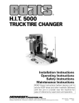
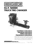
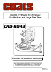
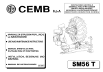
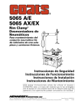
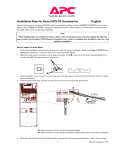
®
H.I.T. 5000H2
TRUCK TIRE CHANGER
Installation
Operating
Safety
Maintenance
Instructions
Instructions
Instructions
Instructions
READ these instructions before placing unit in
service KEEP these and other materials delivered
with the unit in a binder near the machine for
ease of reference by supervisors and operators.
1601 J. P. Hennessy Drive, LaVergne, TN USA 37086-3565 615/641-7533 800/688-6359
HENNESSY INDUSTRIES INC. Manufacturer of AMMCO®, COATS® and BADA® Automotive Service Equipment and Tools.
Manual Part No.: 8184121 00
Revision:
8/00
Safety
ii • COATS H.I.T. 5000H2 Changer
Contents
Table of Contents
Operator Protective Equipment . . . . . . . . . . . . . . . . . . . . . . . . . . . . . . . . . . . . . . . . . . . . . .iv
Definitions of Hazard Levels . . . . . . . . . . . . . . . . . . . . . . . . . . . . . . . . . . . . . . . . . . . . . . . . .iv
Safety Instructions
Bead Loosening . . . . . . . . . . . . . . . . . . . . . . . . . . . . . . . . . . . . . . . . . . . . . . . . . . . . . . . . .v
Demounting & Mounting . . . . . . . . . . . . . . . . . . . . . . . . . . . . . . . . . . . . . . . . . . . . . . . . .v
Inflation . . . . . . . . . . . . . . . . . . . . . . . . . . . . . . . . . . . . . . . . . . . . . . . . . . . . . . . . . . . . . . . .v
Installation . . . . . . . . . . . . . . . . . . . . . . . . . . . . . . . . . . . . . . . . . . . . . . . . . . . . . . . . . . . . . . .vi
Electrical Installation . . . . . . . . . . . . . . . . . . . . . . . . . . . . . . . . . . . . . . . . . . . . . . . . . . . . . . .vi
Principal Operating Parts
Specifications . . . . . . . . . . . . . . . . . . . . . . . . . . . . . . . . . . . . . . . . . . . . . . . . . . . . . . . . . . .1
Wheel Clamping . . . . . . . . . . . . . . . . . . . . . . . . . . . . . . . . . . . . . . . . . . . . . . . . . . . . . . . . . . .2
Tubeless, Duplex & Supersingle Tires
Bead Loosening . . . . . . . . . . . . . . . . . . . . . . . . . . . . . . . . . . . . . . . . . . . . . . . . . . . . . . . . .3
Demounting . . . . . . . . . . . . . . . . . . . . . . . . . . . . . . . . . . . . . . . . . . . . . . . . . . . . . . . . . . . .3
Mounting . . . . . . . . . . . . . . . . . . . . . . . . . . . . . . . . . . . . . . . . . . . . . . . . . . . . . . . . . . . . . .4
Wheels with Lock Rings
Bead Loosening and Demounting . . . . . . . . . . . . . . . . . . . . . . . . . . . . . . . . . . . . . . . . . .5
Mounting . . . . . . . . . . . . . . . . . . . . . . . . . . . . . . . . . . . . . . . . . . . . . . . . . . . . . . . . . . . . . .5
Farm Tires
Bead Loosening . . . . . . . . . . . . . . . . . . . . . . . . . . . . . . . . . . . . . . . . . . . . . . . . . . . . . . . . .6
Demounting . . . . . . . . . . . . . . . . . . . . . . . . . . . . . . . . . . . . . . . . . . . . . . . . . . . . . . . . . . . .6
Mounting . . . . . . . . . . . . . . . . . . . . . . . . . . . . . . . . . . . . . . . . . . . . . . . . . . . . . . . . . . . . . .7
Hutchinson Run Flat Tires
Demounting . . . . . . . . . . . . . . . . . . . . . . . . . . . . . . . . . . . . . . . . . . . . . . . . . . . . . . . . . . . .8
Mounting . . . . . . . . . . . . . . . . . . . . . . . . . . . . . . . . . . . . . . . . . . . . . . . . . . . . . . . . . . . . .10
Hutchinson LAV-III Military Tire
Extended Service Kit Items . . . . . . . . . . . . . . . . . . . . . . . . . . . . . . . . . . . . . . . . . . . . . . .13
Demounting . . . . . . . . . . . . . . . . . . . . . . . . . . . . . . . . . . . . . . . . . . . . . . . . . . . . . . . . . . .13
Tire Spreading . . . . . . . . . . . . . . . . . . . . . . . . . . . . . . . . . . . . . . . . . . . . . . . . . . . . . . . . .15
Mounting . . . . . . . . . . . . . . . . . . . . . . . . . . . . . . . . . . . . . . . . . . . . . . . . . . . . . . . . . . . . .16
Tire Spreading
Method A: . . . . . . . . . . . . . . . . . . . . . . . . . . . . . . . . . . . . . . . . . . . . . . . . . . . . . . . . . . . . .19
Method B: . . . . . . . . . . . . . . . . . . . . . . . . . . . . . . . . . . . . . . . . . . . . . . . . . . . . . . . . . . . . .19
Maintenance . . . . . . . . . . . . . . . . . . . . . . . . . . . . . . . . . . . . . . . . . . . . . . . . . . . . . . . . . . . . .20
Truck Tire Changer Warranty Policy . . . . . . . . . . . . . . . . . . . . . . . . . . . . . . . . . . . . . . . . .Back
Service Policy . . . . . . . . . . . . . . . . . . . . . . . . . . . . . . . . . . . . . . . . . . . . . . . . . . . . . . . . . .Back
COATS H.I.T. 5000H2 Changer • iii
Safety
WARNING
Read entire manual
before assembling,
installing, operating,
or servicing this
equipment.
WARNING
Failure to follow danger, warning, and caution
instructions may lead to serious personal injury or
death to operator or bystander or damage to property. Do not operate this machine until you read
and understand all the dangers, warnings and cautions in this manual. For additional copies of either,
or further information, contact:
Hennessy Industries, Inc.
1601 J.P. Hennessy Drive
LaVergne, TN 37086-3565
(615) 641-7533 or (800) 688-6359
www.ammcoats.com
Operator Protective
Equipment
Personal protective equipment helps make tire servicing safer. However, equipment does not take the
place of safe operating practices. Always wear durable
work clothing during tire service activity. Loose fitting
clothing should be avoided. Tight fitting leather gloves
are recommended to protect operator’s hands when
handling worn tires and wheels. Sturdy leather work
shoes with steel toes and oil resistant soles should be
used by tire service personnel to help prevent injury in
typical shop activities. Eye protection is essential during tire service activity. Safety glasses with side
shields, goggles, or face shields are acceptable. Back
belts provide support during lifting activities and are
also helpful in providing operator protection.
Consideration should also be given to the use of hearing protection if tire service activity is performed in an
enclosed area, or if noise levels are high.
iv • COATS H.I.T. 5000H2 Changer
Definitions of Hazard
Levels
Identify the hazard levels used in this manual with
the following definitions and signal words:
DANGER
Watch for this symbol:
DANGER
It Means: Immediate hazards, which will result in
severe personal injury or death.
WARNING
Watch for this symbol:
WARNING
It Means: Hazards or unsafe practices, which could
result in severe personal injury or death.
CAUTION
Watch for this symbol:
CAUTION
It Means: Hazards or unsafe practices, which may
result in minor personal injury or product or property
damage.
Watch for this symbol! It means BE ALERT! Your
safety, or the safety of others, is involved!
Safety
Safety Instructions
WARNING
Only properly trained personnel should
service tires on the H.I.T. 5000H2. Read all
safety and operating instructions thoroughly before using the tire changer.
ALWAYS remove all wheel weights and the valve
core to deflate the tire before servicing.
ALWAYS cover the electric motor and switch box
before hosing down the tire changer. Be sure water
does not enter the motor or switch box.
ALWAYS disconnect the electric power and air supply before attempting any maintenance.
ALWAYS keep all working surfaces clean and free of
tire lube buildup.
ALWAYS be aware of what each person is and will do
before attempting any two-person operation.
Bead Loosening
NEVER place anything between the bead loosener
disc and the tire/wheel.
NEVER place any part of your body between the
bead loosener disc and the tire/wheel, severe bodily
injury may result.
NEVER allow the bead loosener to contact the
wheel, wheel damage may occur.
Demounting & Mounting
NEVER stand on the working table while demounting or mounting a tire.
ALWAYS keep hands, feet, and other objects away
from moving parts while the machine in turned on.
ALWAYS place the narrow bead seat to the outside
when clamping. Failure to demount the tire from the
narrow bead seat side may cause damage to the tire
beads.
ALWAYS apply an approved rubber lubricant to rim
flanges and both tire beads before demounting or
mounting and seating the beads. NEVER use
antifreeze, silicone, or petroleum base lubricants.
ALWAYS clean and inspect the wheel.
NEVER mount a tire on a damaged or rusty wheel.
Wheel damage or rust may cause tire or wheel failure
during inflation. Explosion from failure may result in
severe injury or death of the operator and bystanders.
ALWAYS be sure the bead opposite the tool is in the
drop center before rotating the tire when demounting
or mounting to avoid damage to the tire beads.
Inflation
ALWAYS follow all applicable Local, State, and
Federal Codes, Rules, and Regulations; such as the
Federal OSHA Standard Number 1910.177.
NEVER seat beads or inflate a tire on the tire
changer. The H.I.T. 5000H2 is not designed as a safety
device or stand for bead seating or inflation.
ALWAYS use an approved inflation chamber or inflation cage.
COATS H.I.T. 5000H2 Changer • v
H.I.T. 5000H2
Installation
Electric Installation
It is not necessary to bolt the H.I.T. 5000H2 to the
floor. However, if desired, use the holes provided in
the base of the machine.
The H.I.T. 5000H2 requires 220 volts, 60 cycle, single
phase power, with a 20 amp circuit. An optional model
is available for 110 volt, single phase.
CAUTION
Most electrical codes require machinery
that is permanently installed to be wired
directly to the power source via conduit.
Remove the H.I.T. 5000H2 from the shipping pallet
and position on a relatively level and smooth floor,
preferably concrete.
Important: Read this operators manual thoroughly
before attempting to change any tires. Also, actuate
the controls several times to become familiar with
their function and direction.
vi • COATS H.I.T. 5000H2 Changer
Important: Have a licensed electrician connect the
H.I.T. 5000H2 to the power source. The licensed electrician must sign the warranty registration card to validate the warranty.
H.I.T. 5000H2
Principal Operating Parts
Pressure Adjusting
Knob
Oil Reservoir
Cap
Hydraulic
Pressure Gauge
On/Off
Switch
Wheel Chuck
Assembly
Clamp Control
Lever
Rotation Control
Lever
Compressor Assembly
Vertical Control
Lever
Inner Tire
Side Plates
Horizontal Control
Lever
Table Control
Lever
Bead Roller
Tool
Tire Spreader
Table Assembly
Combo Tool
“Tee”
Lube Bottle
& Swab
Socket & Ratchet
Release Rod
Short Nylon Web Strap
Bead Spreaders
Long Nylon Web Strap
Specifications
Working Area: 10 Foot Wide x 12 Foot Long x 8 Foot Height
Weight:
1,600 Pounds
Handles Tires: Truck - 15 Inches to 24.5 Inches Tube-type and Tubeless
Grader, Industrial and Farm - 16 Foot to 42 Inches
Military Run Flats - 15 Inches to 24.5 Inches
COATS H.I.T. 5000H2 Changer • 1
H.I.T. 5000H2
Wheel Clamping
The self-centering chuck is powered by the high pressure hydraulic system to securely lock onto the wheel.
Important: The hydraulic pressure regulator knob,
located on the swinging pod front, should normally be
set to 1500 PSI. This pressure should be reduced when
mounting or demounting weak or light weight wheels.
1. Roll the wheel onto the platform with the drop
center (or the split ring) away from the chuck. Position
the valve stem between two of the jaw clamps so the
stem will not be damaged when the wheel is clamped.
2. Rotate the chuck until one of the jaw clamps is in
the 12 o'clock position.
3. Open the jaw clamps slightly larger than the opening you are clamping, then move the jaw clamps up or
down to the approximate center of the wheel. Refer to
the wheel drawings on this page for suggested methods of clamping various types of wheels.
4. Lower the jaw clamps until you can position the
wheel on the top jaw clamp. Raise the chuck, which
will also raise the wheel off the platform.
5. Slowly retract the jaw clamps until the wheel falls
into the proper position for clamping. Clamp the wheel
by pulling the control lever toward you until the
hydraulic motor stalls. Release the handle and the
wheel is ready for mounting or demounting.
2 • COATS H.I.T. 5000H2 Changer
H.I.T. 5000H2
Tubeless, Duplex, and Supersingle Tires
Bead Loosening
1. After locking the wheel on the chuck, remove the
valve core and deflate the tire completely.
5. While the tire is still rotating, apply a liberal
amount of tire lubricant to the tire bead and the rim.
6. Raise the chuck and back the tool away from the
tire, being careful not to contact the rim.
2. Position the bead loosening disc in one of the
square holes in the carriage closest to the outer edge
of the tire.
7. Move the bead loosening disc to the rear of the
tire and repeat the steps above to loosen the rear
bead.
Note: Tire lubricant is very important in the demounting and mounting process. While the bead loosening
tool is pushing the bead away from the rim edge, liberally lube both beads and the rim. FAILURE TO APPLY
LUBE COULD RESULT IN DAMAGE TO THE TIRE
BEAD.
Note: Applying a liberal amount of lube to the tire
sidewall prior to bead loosening will make the tire
more pliable and therefore reduce the likelihood of
damage to the sidewall.
Demounting
1. If the rim has an inclined edge of 15 degrees, continue the bead loosening procedure for the rear bead
until the tire has been pushed off the rim.
3. Rotate the tire. While the tire is rotating, slowly
advance the bead loosening disc to contact the tire
bead. Adjust the chuck up or down so the disc is close
to the rim.
CAUTION
Do not contact the rim with the bead loosening disc. Damage to the rim may result.
4. Once the rim edge is cleared, the chuck may be
lowered to move the disc closer to the tire bead.
Continue moving the disc toward the machine until the
bead is loosened.
CAUTION
The bead opposite the disc must be in the
drop center of the rim. Damage to the bead
may occur if the bead is not in the drop center.
2. If the rim has no edge, or has a stiff sidewall,
retract the disc and remove it from the carriage. Place
the combo tool and tee into position near the outer rim
edge.
COATS H.I.T. 5000H2 Changer • 3
H.I.T. 5000H2
3. Position the combo tool near the edge of the rim
as shown. DO NOT CONTACT THE RIM.
3. Tighten the locking handle and move the tool into
position near the edge of the rim, as shown above.
4. Insert the bead lifting tool between the rim and
bead at a point near the right side of the tool.
4. Securely clamp the vise grip to the rim edge at a
position to the left of the combo tool. Rotate the chuck
clockwise until the vise grip hooks the inner bead and
lifts the tire.
5. Pry the bead out over the rim. Note: You may have
to assist the bead opposite the tool into the drop center. Use one of the tire tools to pry the top bead into
the drop center.
6. Rotate the wheel counterclockwise while maintaining pressure on the bead lifting tool until the first
bead is off.
7. Repeat the steps above for the rear bead.
8. Retract the tool and remove the tire.
Mounting
1. LUBE BOTH BEADS LIBERALLY.
2. Roll the tire onto the carriage and lean it back
against the rim.
4 • COATS H.I.T. 5000H2 Changer
5. Continue rotating the chuck until the first bead is
mounted. Avoid rotating the vise grip into the
combo tool.
6. Remove the vise grip and repeat the steps above
to mount the outer bead.
CAUTION
When mounting a tire, the bead must be
started in the drop center of the rim. Failure
to use the drop center could result in damage to the tire bead.
Note: It may be necessary to push the bead(s) into
the drop center during the mounting process.
Note: Tire lubricant greatly reduces the force needed
to demount or mount a tire. Liberally lube each bead
and rim edge while the bead loosener disc holds the
bead away from the rim. FAILURE TO APPLY LUBE
COULD RESULT IN DAMAGE TO THE TIRE BEADS.
H.I.T. 5000H2
Wheels with Lock Rings
Bead Loosening and Demounting
1. After chucking the wheel, position the bead
loosener disc against the sidewall within 1/4 inch of the
lock ring. Do not contact the ring.
2. Rotate the wheel and slowly advance the bead
loosener disc until the bead is loosened. LIBERALLY
LUBE THE TIRE BEAD AND RIM.
5. Rotate the wheel and slowly advance the disc to
push the tire about half way off the wheel. Push the
valve stem inside the wheel, then finish pushing the
tire off the wheel.
CAUTION
The tube will be damaged if the operator
fails to push the valve stem into the wheel
before completely removing the tire.
Mounting
1. Roll the tire onto the carriage, and align the rim to
the center of the tire.
2. Liberally lube both beads and the rim. Slowly
advance the carriage and guide the tire onto the rim.
Stop about 1/3 of the way on and insert the tube.
3. Place the bead loosening disc in the carriage.
Position it against the tire bead and push the tire onto
the rim.
4. With the disc pushing on the outer sidewall, install
the ring(s).
3. Use the ring tool to remove the lock ring(s).
4. Raise the tire and move the bead loosening disc
into position on the inner bead. Do not contact the rim.
COATS H.I.T. 5000H2 Changer • 5
H.I.T. 5000H2
Farm Tires
Bead Loosening
1. Remove the valve core. Deflate the tire away from
the machine and remove any calcium chloride or other
substances from the tire prior to rolling the wheel onto
the tire changer.
4. Continue to rotate the tire and apply a liberal
amount of lube to the bead and the rim.
5. Move the bead loosening tool to the inner bead
and repeat the above steps.
Note: Tire lubricant greatly reduces the force needed
to demount or mount a tire. Liberally lube each bead
and rim edge while the bead loosener disc holds the
bead away from the rim. FAILURE TO APPLY LUBE
COULD RESULT IN DAMAGE TO THE TIRE BEADS.
Demounting
2. After locking the wheel on the chuck, move the
bead loosening disc into position near the edge of the
rim.
1. Advance the combo tool close to the rim, with the
finger past the rim edge.
Note: Apply a liberal amount of lube to the tire sidewall. This will regain some of the original flexibility of
the rubber, thus reducing possible damage to the sidewall.
3. Rotate the wheel and slowly move the bead loosening disc into the sidewall until the bead is loosened.
6 • COATS H.I.T. 5000H2 Changer
2. With the spade tool inserted between the rim and
the outer bead, on the right of the combo tool, pry the
bead out over the rim edge.
H.I.T. 5000H2
3. Rotate the wheel counterclockwise while maintaining pressure on the spade tool until the outer bead
is demounted. Push the valve stem inside the rim and
pull the inner tube out of the tire.
Note: It is possible to roll one or both beads(s) off the
rim with the bead loosener disc instead of the combo
tool. However, care must be taken not to damage the
tube or the valve stem. By alternately rotating the
wheel first counterclockwise, then clockwise, being
careful not to pass over the valve stem, the tire may be
demounted using this method. If the tire is wide, the
rim is thin or weak, or the side wall is tough, do not use
this method since the bead or the rim may be damaged.
3. Move the combo tool into position near the edge
of the rim.
Note: Mounting of the outer bead is shown in order
to see the position of the tools. Position of the tools
will be the same for the inner bead.
4. Lean the tire against the rim and clamp the vise
grip on the edge of the rim to the left of the combo
tool. Rotate the chuck to lift off the carriage.
Note: Tire lubricant greatly reduces the force needed
to demount or mount a tire. Liberally lube each bead
and rim edge while the bead loosener disc holds the
bead away from the rim. FAILURE TO APPLY LUBE
COULD RESULT IN DAMAGE TO THE TIRE BEADS.
5. Using one of the tire tools to assist the bead into
drop center, continue rotating the chuck until the inner
bead is mounted.
Mounting
1. Lube both beads and the rim liberally.
2. Rotate the rim so the valve stem hole is directly
on the bottom, then roll the wheel onto the carriage.
6. Insert the inner tube and repeat the above steps
to mount the outer bead.
Note: Avoid damage to the valve stem by never
allowing the stem to pass the stationary tool.
COATS H.I.T. 5000H2 Changer • 7
H.I.T. 5000H2
Hutchinson Run Flat Tires
Demounting
1. By operating the carriage to the extended position, the table will be rotated to the horizontal position.
4. When the table is in the vertical position, manually
center the tire and rim so that it lies perpendicular to
the table cylinder.
5. Place the tire compressor on top of the tire and
pin it to the clevis affixed to the table cylinder.
CAUTION
Adjust the four arms of the compressor to
just clear the lock ring.Tighten all of the "T"
handles so they won't move.
WARNING
Ensure at this point that the tire has been
completely deflated and the valve core
removed from the valve stem.
2. Place the tire and rim over the table top by rolling
into place and then leaning back onto the table.
3. Again, using carriage handle, rotate table back to
vertical position. As this occurs, the tire and rim will follow and end up sitting on top of the table.
CAUTION
Ensure that table cylinder is retracted when
the above operation is done so there will be
no damage to the cylinder shaft.
6. Compress the retaining ring and tire down enough
to clear the lock ring. Using the ring tool, remove the
lock ring.
7. Extend the table cylinder and remove the compressor, lock ring, retaining ring and rim seal.
8. Rotate table to the horizontal position. Remove
tire and rim, then replace them after turning them 180
degrees.
9. Rotate table back to vertical position.
Note: Rim face should now be on bottom.
10. Reinstall compressor and pin it to the clevis
affixed to the table cylinder.
8 • COATS H.I.T. 5000H2 Changer
H.I.T. 5000H2
11. Using table cylinder, press tire and inner tire
down off of rim.
12. Remove compressor and rim from table top.
13. Rotate table to horizontal position and remove
inner and outer tire from table.
15. Using the longest of the two nylon web straps,
place the strap around the top of the inner tire and the
cross brace of the table linkage. The carriage should be
in the retracted position. Using socket and ratchet,
tighten strap as shown.
Note: The vertical cylinder should be lowered to a
point where the tire just clears the carriage.
14. Roll tire onto carriage platform and clamp bead
into deepest "V" in jaws.
CAUTION
The hydraulic pressure regulator knob,
located on the swinging pod front, should
be set at minimum pressure. Also, care
should be taken to ensure that the beads
are not overly stretched.
16. Move the carriage to the extended position,
thus pulling the inner tire out of the outer tire. If the
two tires are not separated when the carriage has
reached its extended position, further travel can be
reached by raising the vertical cylinder until the two
tires are separated.
17. Remove the web strap from the inner tire, and
remove the outer tire from the clamps of the machine.
COATS H.I.T. 5000H2 Changer • 9
H.I.T. 5000H2
Mounting
6. Raise the clamps and remove the strapped inner
tire from the side plates. Then remove the side plates
from the carriage.
1. Place the two inner tire side plates into the carriage forward holes facing each other as shown above.
2. Place the shortest nylon web strap down on the
center of the two side plates.
Note: Ensure that the ratchet end of the strap is to the
outboard of the side plates and the flat side is facing up.
3. Roll the inner tire over the strap and between the
two side plates. Ensure that the two slits in the inner
tire are placed opposite one another and parallel to the
ground.
4. Compress the inner tire by pushing down on it
with the clamps.
7. Roll the outer tire onto the carriage and clamp the
bead into the deepest "V" in jaws.
CAUTION
The hydraulic pressure regulator knob,
located on the swinging pod front, should
again be set at minimum pressure. Also, care
should be taken to ensure that the beads are
not overly stretched.
Note: The jaws should be spread to a point that the
arms are parallel to the ground. While compressing the
inner tire, ensure that the inner tire is maintained in a
vertical position.
8. Place the two bead spreaders into the lower edge
of the bead with the other end hooked into the openings of the tire ramps (angles welded to the side rails).
Then, lift the tire up until the bead is spread open
slightly.
5. After the inner tire is compressed to its lowest
point, place strap around inner tire and tighten with
socket and ratchet as shown above.
10 • COATS H.I.T. 5000H2 Changer
Note: Apply a liberal amount of lube to the front bead
of the outer tire and the edges of the spreaders in the
area of the bead.
H.I.T. 5000H2
9. Place the combo tool "tee" into the carriage with
the "tee" perpendicular to the carriage cylinder and platform on the side facing outer tire. Also, extend carriage.
10. Start inner tire into outer tire and place lower
end onto platform on side of combo tool "tee".
11. Move carriage rearward, retract, and push inner
tire into outer tire.
14. Remove short web strap from inside of outer
tire.
15. Lower both tires to carriage and remove from
machine.
16. Extend carriage, rotating table to horizontal position.
17. Place rim over table top and tire over cylinder
shaft. Apply liberal amount of tire lube to rim as shown
above.
18. Extend table cylinder shaft fully. Now retract carriage cylinder and rotate table, tire and rim to vertical
position.
19. Place retaining ring over cylinder shaft. Now
install compressor onto clevis affixed to rod end of
table cylinder.
12. When inner tire is inside outer tire, use release
rod by hooking over release bar on strap clamp as
shown above.
13. After ensuring that everything and everyone is
clear, release strap with quick pull on release rod.
WARNING
Inner tire will expand rapidly, and with much
force. Ensure that release rod is used when
releasing catch. FAILURE TO DO SO COULD
RESULT IN SERIOUS INJURIES.
20. Press both tires down over rim. Push tire down
below lock ring groove.
COATS H.I.T. 5000H2 Changer • 11
H.I.T. 5000H2
21. Remove compressor and retaining ring.
22. Place rim seal down around rim and under bead.
23. Place retaining ring, and lock ring, on top of tire.
24. Install compressor onto clevis affixed to rod end
of table cylinder.
27. Raise table cylinder and remove compressor.
28. Extend carriage cylinder rotating table to horizontal position.
29. Remove mounted tire from machine.
ALWAYS follow all applicable Local, State, and Federal
Codes, Rules, and Regulations; such as the Federal
OSHA Standard Number 1910.177.
NEVER seat beads or inflate a tire on the tire changer.
The H.I.T. 5000H2 is not designed as a safety device or
stand for bead seating or inflation.
ALWAYS use an approved inflation chamber or inflation cage.
DANGER
25. Press retaining ring down on rim seal and outer
tire bead down below lock ring groove.
26. Install lock ring and insure that it is down properly in lock ring groove.
12 • COATS H.I.T. 5000H2 Changer
Tire failure under pressure can be hazardous. Place the wheel inside an approved
inflation chamber or cage before inflating.
Use an approved remote inflation valve,
hose, and gauge. ALWAYS wear safety goggles for eye protection. Do not stand beside
the wheel or cage during inflation. Keep
hands and other parts of the body out of the
cage during inflation. Observe the tire pressure frequently. Do not exceed the manufacturer's recommended maximum inflation
pressure. Failure to follow these instructions may cause the tire and rim to separate
with tremendous force, resulting in serious
personal injury or death.
H.I.T. 5000H2
Hutchinson LAV-III Military Tire
Extended Service Kit Items
Hennessy Model 8090011 (GM 10603931) - H.I.T.
5000H2 Tire changer with extended kit.
Hennessy Kit 183970 (GM 10603930) - Extended
service kit ordered separately.
Item
No.
Part
No. Qty. Description
1
183959 1
Wing Set, LAV-III
2
183971 1
End Plate, LAV-III
3
183972 1
4" Strap & Buckle Assembly
4
183967 1
Spreader-Straight, LAV-III
5
184125
Screwdriver, KD Tool
6
184047 1
Yoke, Ram Extension
7
109626 1
Locking Pin, Cylinder Extension
8
110852
1
Offset Roller
110829
3
Clamp Jaws, #183970 Kit only (not
shown)
1
Note: Due to a design change, be sure to replace the
jaws on a H.I.T. 5000H model older than 1993. New
jaws are supplied in the 183970 kit. Also, replace the
jaws on a 1993 or newer production H.I.T. 5000H
model only if the ones on the machine are worn.
Demounting
1. Place the support table over the ram at the end of
the machine with the center shaft upward. Extend the
ram slightly to keep it in place.
2. Install the ram extension yoke, locking it and the
plate in position with the extra clevis pin.
3. Extend the carriage, moving the end plate into a
vertical position.
4. Stand the wheel upright and walk it into place,
against the end plate, with the wheel bolts facing outward.
5. With another person holding the wheel in place,
move the carriage in, bringing the end plate and wheel
up into a horizontal position.
WARNING
ALWAYS be aware of what each person is
and will do before attempting any two-person operation.
COATS H.I.T. 5000H2 Changer • 13
H.I.T. 5000H2
10. With another person holding the wheel in place,
extend the carriage to move the wheel and end plate
back to the vertical position.
WARNING
ALWAYS be aware of what each person is
and will do before attempting any two-person operation.
11. Roll the wheel around and onto the carriage.
6. Remove the pressure sensor tubing. Remove the
wheel nuts.
7. Extend the ram to full length, install the yoke
extension, and tire compressor making sure that the
legs will not catch on the edge of the rim.
8. Actuating the ram downward, move the tire off of
the bead seat.
12. Move the carriage inward to position the wheel
with the jaws in the center. Expand the arms so that
the outer notch in the jaws clamp onto the inner rim of
the wheel.
CAUTION
Use care to avoid contact with the studs
and air intake pipe, which can result in damage to the rim.
13. Raise the wheel and place the super single/dual
wheel roller assembly in the carriage hole closest to
the body of the machine behind the tire.
9. Remove the tire compressor and upper rim section.
14 • COATS H.I.T. 5000H2 Changer
H.I.T. 5000H2
again be set at minimum pressure. Also,
care should be taken to ensure that the
beads are not overly stretched.
CAUTION
Always keep your hands out of the jaw area.
20. Expand the arms and move the last jaw into
place. This may require using a screwdriver from the
back to guide the last bead into a secure position.
21. When all three jaws are properly holding the
bead, expand the arms as much as possible but not
exceeding 1500 psi.
22. Move the carriage all the way in and lower the
tire to the carriage.
14. Lower the wheel to the point where the roller
assembly can be moved forward without catching on
the rim.
15. Move the carriage out slowly while rotating the
tire, which will move the tire and insert off of the rim.
23. Guide the 4 inch wide strap between the tire
and the run flat insert at top dead center and loop it
back through the center hole. Connect the strap
around the forward cross bar on the machine’s carriage.
16. Remove the rim from the tire changer and set
aside.
17. Rotate the arms until one jaw is straight up.
18. Roll the tire and insert back onto the carriage.
Lean the tire assembly away from the machine and
move the carriage inward. When the tire is over the
jaws, raise the arms until the top jaw securely hooks
the bead of the tire.
24. Raise the tire to full height and move the carriage all the way out. If the insert does not come clear
in one stroke, bring the tire down and the carriage in
allowing the strap to be shortened. If the insert is
almost out, take up some slack by rotating the tire two
or three revolutions; twisting the strap.
19. Raise the tire and rotate until a second jaw has
hooked the bead.
CAUTION
The hydraulic pressure regulator knob,
located on the swinging pod front, should
CAUTION
Stand back when removing the run flat
insert, which can clear the tire quickly.
25. Remove the tire from the machine by retracting
the arms.
COATS H.I.T. 5000H2 Changer • 15
H.I.T. 5000H2
Mounting
1. Re-clamp a new tire onto the jaws of the tire
changer.
2. Place the two bead spreaders into the lower edge
of the bead with the other end hooked into the openings of the tire ramps (angles welded to the side rails).
On a new tire this may be difficult. Also, a third bead
spreader is provided that may be hooked between the
bead and the carriage.
shape. Tighten the buckle until the widest part of the
insert is at or close to 20 inches / 51 cm across. Note:
The smaller the cross section, the easier it is to install
the run flat insert into the tire.
6. Liberally grease the run flat insert and tire bead
with an approved tire grease.
3. Then, move the carriage back until the bead is
spread open slightly.
4. On the floor spread out the 4 inch wide strap with
the buckle facing down. Lay the run flat insert on the
strap as close to the buckle as possible and with one
of the three relief grooves lined up on the strap. Bring
the long end of the strap over the insert and install it in
the buckle.
5. Working the handle on the buckle, draw the insert
together allowing the sides to come up into a banana
16 • COATS H.I.T. 5000H2 Changer
7. Lift the run flat insert and put one end in the tire
far enough for the buckle to be beyond the bead of the
tire. Rotate the insert until the buckle is facing down.
Note: the larger end of the insert should be in the tire
and at the top.
8. Install the ‘T’ arm in the carriage. Install the wing
set guide into the ‘T’.
9. Move the carriage forward pushing the insert into
the tire. Stop once the bottom edge of the insert is
past the edge of the bead.
H.I.T. 5000H2
10. Move the carriage back out allowing the insert
to drop fully into the tire. Note: This may require adjusting the height of the tire while moving the carriage
inward.
11. Remove the ‘T’ arm from the carriage.
12. Move the carriage back into the machine and
lower the tire assembly onto the carriage.
13. Release the jaws by collapsing the arms.
Remove the tire assembly from the tire changer.
19. Move the tire to the rim, leaning the tire slightly
towards the rim.
20. Lift the rim, catching the insert and then the tire.
14. Lay the tire and insert on the floor with the strap
buckle facing up and use the long tire bar to release the
lock on the strap.
CAUTION
Do not attempt to release the lock by hand.
The run flat insert expands rapidly.
CAUTION
Damage to the insert may occur if care is
not taken to clear the edge of the rim.
21. Keep pressure on both sides of the tire, while
rotating the tire and rim slowly, until the tire and insert
are on the rim. This may require using the screwdriver
to guide the last part of the insert into place.
15. Re-clamp the large rim section onto the tire
changer.
16. Clean the rim thoroughly and remove any light
nicks in the metal. Significant damage may require the
replacement of the wheel.
17. Liberally grease the rim to aid in the installation
of the tire and insert assembly.
18. Roll the tire back onto the carriage.
22. Remove the tire and rim assembly from the tire
changer’s jaws and then move the wheel to the end of
the machine.
COATS H.I.T. 5000H2 Changer • 17
H.I.T. 5000H2
23. Extend the carriage, moving the end plate into a
vertical position.
24. Stand the wheel upright and walk it into place,
against the end plate, with the wheel bolts facing outward.
25. With one person holding the wheel in place,
move the carriage in, bringing the end plate and wheel
up into a horizontal position.
29. Draw the sections together using a cross pattern
on the wheel bolts. Torque to wheel manufacturer’s
specifications.
30. With someone to stabilize the wheel, extend
the carriage to move the wheel and end plate back to
the vertical position.
31. Remove mounted tire from machine.
ALWAYS follow all applicable Local, State, and Federal
Codes, Rules, and Regulations; such as the Federal
OSHA Standard Number 1910.177.
CAUTION
Be careful not to cut the insert or bend the
rim flange when clearing the edge of the
rim.
26. Use the screwdriver to guide the second edge
of the insert, which has a recess inside, over the lip of
the rim.
27. Install a new seal in the lower rim section using
liberal amounts of tire grease.
28. Place the second rim section on top of the
assembly.
18 • COATS H.I.T. 5000H2 Changer
NEVER seat beads or inflate a tire on the tire changer.
The H.I.T. 5000H2 is not designed as a safety device or
stand for bead seating or inflation.
ALWAYS use an approved inflation chamber or inflation cage.
DANGER
Tire failure under pressure can be hazardous. Place the wheel inside an approved
inflation chamber or cage before inflating.
Use an approved remote inflation valve,
hose, and gauge. ALWAYS wear safety goggles for eye protection. Do not stand beside
the wheel or cage during inflation. Keep
hands and other parts of the body out of the
cage during inflation. Observe the tire pressure frequently. Do not exceed the manufacturer's recommended maximum inflation
pressure. Failure to follow these instructions may cause the tire and rim to separate
with tremendous force, resulting in serious
personal injury or death.
H.I.T. 5000H2
Tire Spreading
There are two methods of spreading the tire with the
roller tool.
Method A:
Method B:
1. With the first bead removed, hook the roller tool
over the outer bead and move the tool away from the
rim to spread the beads and gain access to the inside
of the tire.
1. With the tire completely demounted and the rim
removed from the clamps, hook the inner bead over
the clamps and the roller tool over the outer bead.
Move the tool away from the inner bead to gain access
to the inside of the tire.
Note: The wheel can be rotated with the roller tool still in place,
but the tool should be moved toward the wheel slightly. This will
relieve some of the pressure on the bead, thus avoiding any
damage, which might occur from over stretching the bead.
DANGER
Tire failure under pressure can be hazardous. Place
the wheel inside an approved inflation chamber or
cage before inflating. Use an approved remote inflation valve, hose, and gauge. ALWAYS wear safety
goggles for eye protection. Do not stand beside the
wheel or cage during inflation. Keep hands and other
parts of the body out of the cage during inflation.
Observe the tire pressure frequently. Do not exceed
the manufacturer's recommended maximum inflation pressure. Failure to follow these instructions
may cause the tire and rim to separate with tremendous force, resulting in serious injury or death.
COATS H.I.T. 5000H2 Changer • 19
H.I.T. 5000H2
Maintenance
1. Using a grease gun and chassis grease, lubricate
chuck hub bushing once every month.
3. Using a grease gun and chassis grease, lubricate
the disk shaft on the bead roller tube once every
month.
2. Remove the side panels and lubricate the four
posts that guide the carriage up and down. Also, with
a grease gun, lubricate the bushing sprocket tube.
Lubricate these parts at lease once every month.
4. Grease chain and check the tension once every
month and adjust if necessary.
5. Check hydraulic reservoir once every week. With
all hydraulic cylinders retracted, the oil level should be
approximately two inches below the top of reservoir.
Add COATS hydraulic oil (P.N. 120454) to this level.
6. Change the oil filter once every six months. Screw
off the filter and replace with service part number
001631.
20 • COATS H.I.T. 5000H2 Changer
H.I.T. 5000H2
Notes
COATS H.I.T. 5000H2 Changer • 21
Truck Tire Changer Warranty Policy
The COATS Company warrants the H.I.T. 5000H2 Truck Tire Changer to be free of defects in workmanship and
material for a period of twelve (12) months from the date of installation. Labor will be covered by the COATS
Company for a period of 90 days from the date of installation.
Upon inspection by COATS Company or its authorized representative, any defect in workmanship and/or material within the warranty period will be:
Replaced in the field by the user, parts supplied free of charge by the COATS Company, LaVergne, Tennessee,
for the first 12 months of operation. Labor is covered by the COATS Company for the first 90 days of operation.
This warranty is in lieu of all other warranties, expressed or implied, and of all other obligations and/or liabilities,
and no person is authorized to make any other representation or assume any other obligation on behalf of the
manufacturer.
This warranty shall not apply if damage is due to accident, negligence, alteration, abuse or misuse, worn parts,
installation by unlicensed electrician, or has not been operated in accordance with the manufacturer's instructions
for operation. Parts replaced under warranty will assume the remainder of the unit's warranty period. Only parts
and accessories manufactured by the COATS Company will be warranted as stated above and this warranty shall
not apply to the tire changer or any parts thereof if parts and accessories not manufactured by COATS Company
are used as replacements for or in substitution of COATS Company manufactured parts and accessories.
To validate warranty:
1. A licensed electrician must install all electrical requirements and sign the attached warranty registration card.
2. The owner must fill out the post-paid warranty registration card and return it to COATS Company within thirty
(30) days of installation.
Failure to perform 1 above will void warranty coverage on electrical and hydraulic components. Failure to perform
2 may void entire warranty.
Service Policy
Upon recognition of a problem, review the Maintenance Instructions and Service Manual.
If further assistance is required, call:
(800) 688-6359
or
your nearest
Hennessy Regional
Office
The COATS Company will supply a replacement part-no charge- when it is determined by the factory or an
authorized representative that the part is defective in workmanship and/or material and is covered by the warranty
policy. The owner has the option to send the defective part to the COATS Company for inspection, repair or
replacement. All returns to the factory must be authorized by the COATS Company prior to return. Freight to the
factory will be paid by the owner. If the machine is serviced by COATS authorized personnel, labor charges will be
covered for a period of 90 days after the date of installation.
8184121 8/00
© Copyright 2000 Hennessy Industries and COATS
All Rights Reserved
Printed in USA