1
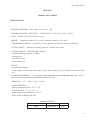
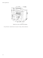
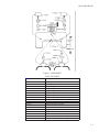
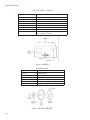
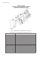
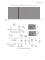
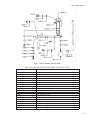
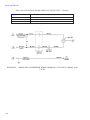
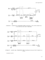
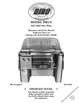
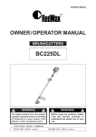
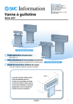
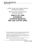
S6161-LQ-FSE-010
0910-LP-103-2000
[ SGML Version See Change Record ]
TECHNICAL MANUAL
TENDERIZER, MEAT
ELECTRIC
DISTRIBUTION STATEMENT E: DISTRIBUTION AUTHORIZED TO DOD COMPONENTS
ONLY; CRITICAL TECHNOLOGY; DATE OF PUBLICATION. OTHER REQUESTS SHALL
BE REFERRED TO THE NAVAL SEA SYSTEMS COMMAND (SEA-09B2).
WARNING: THIS DOCUMENT CONTAINS TECHNICAL DATA WHOSE EXPORT IS
RESTRICTED BY THE ARMS EXPORT CONTROL ACT (TITLE 22. U.S.C. SEC. 2751 ET.
SEQ.) OR EXECUTIVE ORDER 12470. VIOLATIONS OF THESE EXPORT LAWS ARE
SUBJECT TO SEVERE CRIMINAL PENALTIES.
DESTRUCTION NOTICE: DESTROY BY ANY METHOD THAT WILL PREVENT DISCLOSURE OF CONTENTS OR RECONSTRUCTION OF THE DOCUMENT.
PUBLISHED BY DIRECTION OF COMMANDER, NAVAL SEA SYSTEMS COMMAND
21 APR 1987
TITLE-1 / (TITLE-2 Blank)@@FIpgtype@@TITLE@@!FIpgtype@@
@@FIpgtype@@TITLE@@!FIpgtype@@
TITLE-2
@@FIpgtype@@BLANK@@!FIpgtype@@
S6161-LQ-FSE-010
RECORD OF CHANGES
CHANGE NO.
DATE
TITLE OR BRIEF DESCRIPTION
ENTERED BY
NOTE
THIS TECHNICAL MANUAL (TM) HAS BEEN DEVELOPED FROM AN INTELLIGENT ELECTRONIC
SOURCE KNOWN AS STANDARD GENERALIZED MARKUP LANGUAGE (SGML). THERE IS NO
LOEP. ALL CHANGES, IF APPLICABLE, ARE INCLUDED. THE PAGINATION IN THIS TM WILL NOT
MATCH THE PAGINATION OF THE ORIGINAL PAPER TM; HOWEVER, THE CONTENT IS
EXACTLY THE SAME. ANY CHANGES RECEIVED AFTER RECEIPT OF THIS TM WILL ONLY FIT
IN THIS PAGINATED VERSION.
RECORD OF CHANGES-1 / (RECORD OF CHANGES-2 Blank)
RECORD OF CHANGES-2
@@FIpgtype@@BLANK@@!FIpgtype@@
S6161-LQ-FSE-010
TABLE OF CONTENTS
Chapter/Paragraph
1
Page
MODELS PRO-9 SERIES . . . . . . . . . . . . . . . . . . . . . . . . . . . . . . . .
1-1
SPECIFICATIONS . . . . . . . . . . . . . . . . . . . . . . . . . . . . . . . . . . . . .
1-1
INSTRUCTION SHEET FOR THE BIRO-SIR STEAK MODEL PRO-9
TENDERIZER . . . . . . . . . . . . . . . . . . . . . . . . . . . . . .
TO INSTALL OR REPLACE PORTABLE UNIT: . . . . . . . .
TO REMOVE PORTABLE UNIT: . . . . . . . . . . . . . . . .
TO REMOVE STRIPPERS: . . . . . . . . . . . . . . . . . . . .
TO REMOVE BLADE ASSEMBLIES: . . . . . . . . . . . . . .
TO REPLACE STRIPPERS: . . . . . . . . . . . . . . . . . . . .
TO TIGHTEN BELT: . . . . . . . . . . . . . . . . . . . . . . . .
OILING: . . . . . . . . . . . . . . . . . . . . . . . . . . . . . . .
.
.
.
.
.
.
.
.
.
.
.
.
.
.
.
.
.
.
.
.
.
.
.
.
.
.
.
.
.
.
.
.
.
.
.
.
.
.
.
.
.
.
.
.
.
.
.
.
.
.
.
.
.
.
.
.
1-12
1-13
1-13
1-13
1-13
1-13
1-13
1-13
LIMITED WARRANTY: . . . . . . . . . . . . . . . . . . . . . . . . . . . . . . .
WARRANTY: . . . . . . . . . . . . . . . . . . . . . . . . . . . . . . . . .
DURATION OF WARRANTY: . . . . . . . . . . . . . . . . . . . . . . .
PARTS NOT COVERED BY WARRANTY: . . . . . . . . . . . . . . . .
EXCLUSION OF WARRANTIES AND LIMITATION OF REMEDIES:
REGISTRATION CARDS: . . . . . . . . . . . . . . . . . . . . . . . . . .
HOW TO GET SERVICE: . . . . . . . . . . . . . . . . . . . . . . . . . .
.
.
.
.
.
.
.
.
.
.
.
.
.
.
1-13
1-13
1-14
1-14
1-14
1-14
1-14
i
S6161-LQ-FSE-010
LIST OF TABLES
Table
ii
Title
Page
APPROX. WEIGHTS: . . . . . . . . . . . . . . . . . . . . . . . . . . . . . . . . . . .
1-1
CASE TOP PARTS
. . . . . . . . . . . . . . . . . . . . . . . . . . . . . . . . . . . .
1-3
HOPPER PARTS . . . . . . . . . . . . . . . . . . . . . . . . . . . . . . . . . . . . . .
1-4
PULLEY AND BELT PARTS (See Parts List For Correct Motor) . . . . . . . . . . .
1-5
STANDARD DUTY TRANSMISSION ASSEMBLY PARTS LIST . . . . . . . . . .
1-6
WRAPAROUND CASE PARTS
. . . . . . . . . . . . . . . . . . . . . . . . . . . . .
1-8
PRO-9 SD AND HD BASE FRAME PARTS LIST (REAR VIEW) . . . . . . . . . .
1-9
TROUBLE SHOOTING CHART . . . . . . . . . . . . . . . . . . . . . . . . . . . . .
1-14
PARTS NOT MANUFACTURED BY BIRO
1-15
. . . . . . . . . . . . . . . . . . . . . .
S6161-LQ-FSE-010
LIST OF ILLUSTRATIONS
Figure
Title
Models Pro-9 Series, Specifications Diagram
Page
. . . . . . . . . . . . . . . . . . . . . .
1-2
. . . . . . . . . . . . . . . . . . . . . . . . . . . . . . . . . . . . . . .
1-3
1
CASE PARTS
2
HOPPER
. . . . . . . . . . . . . . . . . . . . . . . . . . . . . . . . . . . . . . . . . .
1-4
3
PULLEY AND BELT . . . . . . . . . . . . . . . . . . . . . . . . . . . . . . . . . . .
1-4
4
STANDARD DUTY TRANSMISSION ASSEMBLY . . . . . . . . . . . . . . . . . .
1-6
5
TENDERIZER CRADLE PARTS . . . . . . . . . . . . . . . . . . . . . . . . . . . . .
1-7
6
WRAPAROUND CASE . . . . . . . . . . . . . . . . . . . . . . . . . . . . . . . . . .
1-8
7
BASE FRAME (REAR VIEW) . . . . . . . . . . . . . . . . . . . . . . . . . . . . . .
1-9
SCHEMATIC - 1 MODEL PRO-9 TENDERIZER WIRING DIAGRAM 115-220
VOLTS/1 PHASE 50-60 CYCLE . . . . . . . . . . . . . . . . . . . . . . . . . . .
1-10
SCHEMATIC - 2 MODEL PRO-9 TENDERIZER WIRING DIAGRAM 115-220
VOLTS/1 PHASE 50-60 CYCLE WITH IN LINE CIRCUIT BREAKER . . . . .
1-11
SCHEMATIC - 3 MODEL PRO-9 TENDERIZER WIRING DIAGRAM
220-380-440 VOLTS/3 PHASE 50-60 CYCLE . . . . . . . . . . . . . . . . . . . .
1-11
iii
S6161-LQ-FSE-010
SAFETY SUMMARY
GENERAL SAFETY NOTICES The following general safety notices supplement the specific warnings
and cautions appearing elsewhere in this manual. They are recommended precautions that must be understood
and applied during operation and maintenance of the equipment covered herein. Should situations arise that are
not covered in the general or specific safety precautions, the commanding officer or other authority will issue
orders as deemed necessary to cover the situation.
DO NOT REPAIR OR ADJUST ALONE Under no circumstances should repair or adjustment of energized equipment be attempted alone. The immediate presence of someone capable of rendering aid is required.
Before making adjustments, be sure to protect against grounding. If possible, adjustments should be made with
one hand, with the other hand free and clear of equipment. Even when power has been removed from equipment
circuits, dangerous potentials may still exist due to retention of charges by capacitors. Circuits must be grounded
and all capacitors discharged prior to attempting repairs.
TEST EQUIPMENT Make certain test equipment is in good condition. If a test meter must be held,
ground the case of the meter before starting measurement; do not touch live equipment or personnel working on
live equipment while holding a test meter. Some types of measuring devices should not be grounded; these
devices should not be held when taking measurements.
INTERLOCKS Interlocks are provided for safety of personnel and equipment and should be used only
for the purpose intended. They should not be battle shorted or otherwise modified except by authorized maintenance personnel. Do not depend solely upon interlocks for protection. Whenever possible, disconnect power at
power distribution source.
WARNING
TO: MACHINE PURCHASERS, OPERATORS AND OPERATIONS
SUPERVISORS
READ AND UNDERSTAND THIS LABEL BEFORE REMOVING THIS
LABEL FROM THIS BIRO MACHINE
READ information manual supplied with this BIRO machine.
DO NOT electric wire machine, have only a qualified and certified electrician wire this machine, as required. Be sure machine is grounded. Failure to
ground this machine could result in electric shock.
DO NOT use this machine for non-food products.
DO NOT attempt to operate machine until unit has been inspected and
demonstrated by the seller-recognized BIRO Representative.
DO NOT attempt to operate this machine unless you have been properly
trained. Improper use or operation of this machine could result in bodily
injury.
iv
S6161-LQ-FSE-010
SAFETY SUMMARY - Continued
DO NOT leave machine in operation - unattended.
DO NOT tamper, bypass, remove fixed guards, safety interlock electrical
switches or other safety devices.
DO NOT at any time force feed machine.
DO NOT alter or modify machine in any way from its original form.
ALWAYS disconnect power supply before removing shrouds, removable
guards, covers, doors, fences, panels for servicing, cleaning or any other reason.
USE only BIRO parts and accessories, properly installed.
MACHINE OPERATING MANUALS as supplied with this unit are available from BIRO.
FAILURE TO COMPLY WITH THIS NOTICE AND WARNING COULD
RESULT IN BODILY INJURY. (Page 1-12)
CAUTION
- TO REPLACE BLADE ASSEMBLIES: Replace rollers with delrin bearing ends into cradle first. Keep flat portion of bearings up so they will fit in
the bearing stop studs. (See tenderizer cradle diagram.) Then align the first
blade on the bearing side of the front blade assembly, fitting between the
first and second blades on the bearing side of the rear blade assembly. (Page
1-13)
v / (vi Blank)
vi
@@FIpgtype@@BLANK@@!FIpgtype@@
S6161-LQ-FSE-010
CHAPTER 1
MODELS PRO-9 SERIES
SPECIFICATIONS
MOTORS STANDARD:
SD 1/2 HP-115V.. 60 cycle, 1 Ph.
MOTORS AVAILABLE - NET EXTRA:
CASE:
HOPPER:
SD-HD 1/2 HP, 115/220 volts, 50 cycle, 1 phase.
Stainless steel side panels and case top.
Transparent standard on 1 Ph. units. Aluminum standard on 3 Ph. units.
″TRANSMISSION″ DRIVE:
CUTTING GROUP:
On SD units, V belt, adjustable. On HD units, timing belt, adjustable.
Stainless steel blades and spacers. Stainless steel combs.
CUTTING GROUPS - AVAILABLE NET EXTRA:
Tenderizer/Knitting group (std. on PRO-9)
Scoring Group
Prick Punch Group
Stew Cutting Group
SAFETY:
Grounded cord and plug
Safety switch to shut off motor when hopper is raised. Special safety devices as required by state and/or localities.
STANDARD EQUIPMENT: Cord and plug, tenderizing/knitting group. On HD units only: same as above,
plus heavy duty transmission with ball bearings and heavier gears.
APPROVALS:
U.L. - N.S.F. - C.S.A. - U.S.D.A.
CHARACTERISTICS:
Hopper opening dimension 1 3/8″ x 7 1/2″
Overall dimension 13″ x 16″ x 16 1/2″
Roller lengths on all standard units - 8 3/16″
Roller speeds: 85 RPM on SD units
APPROX. WEIGHTS:
APPROX. WEIGHT
GROSS
NET
PRO-9
1/2 SD-65 lbs.
54 lbs.
1-1
S6161-LQ-FSE-010
Models Pro-9 Series, Specifications Diagram
All specifications contained herein are subject to change without notification.
1-2
S6161-LQ-FSE-010
Figure 1 CASE PARTS
CASE TOP PARTS
Figure Item Number
Description
T3006-2
TA3006-2
T3061
T3062
T3064
T3066
T3067
T3068
T3069-1
T3069-1C
T3101-1
T3103
T3105
T3186
T3186-1
T3187
T3187-1
T3187-2
Case Top Stainless
Case Top Assy. w/o Switches
Hopper Hinge Nut
Hopper Hinge Washer
Hopper Hinge Spring
Hopper Hinge RH
Hopper Hinge LH
Hopper Hinge Lock Washer
Panhead Screw 10-24 x
Cover Side Screw Clip
Waterproof Toggle Cap Nut
On and Off Plate
Waterproof Safety Switch Cap Nut
Toggle Switch. 1 Phase
Toggle Switch. 3 Phase
Thermal Circuit Breaker. 8 Amp
Thermal Circuit Breaker. 10 Amp
Thermal Circuit Breaker. 12 Amp
1-3
S6161-LQ-FSE-010
CASE TOP PARTS - Continued
Figure Item Number
Description
T3187-3
T3188
T3189
T3190
T3200
T3200-1
T3211
T3290-2
Thermal Circuit Breaker. 5 Amp
Waterproof Reset Button Seal
″Press to Reset″ Plate
Circuit Breaker Lock Washer
Safety Switch. 1 Phase
Safety Switch. 3 Phase
Shakeproof Washer UL
Switches & Wiring Harness Assembly. (1PH)
115v (3 PH also available)
Figure 2 HOPPER
HOPPER PARTS
Figure Item Number
Description
T3059-3
T3059-4
T3076
T3090
T3096
T3096-1
Caution Decal
Warning Decal
BIRO SirSteak Decal
NSF Decal
Aluminum Hopper (3 PH only)
Transparent Hopper w/Decals
Figure 3 PULLEY AND BELT
1-4
S6161-LQ-FSE-010
PULLEY AND BELT PARTS (See Parts List For Correct Motor)
Figure Item Number
Description
T3020
TA3020-6
TA3020-6K
T3021-1
T3024-1
T3024-2
T3024-6A
T3024-7A
T3024-6-1A
Driven Pulley (4 x ½)SD Only (85 RPM)
Driven Timing Pulley w/Bushing (4 x ½)HD Only (115/140 RPM)
Timing Belt & Pulley Kit. (60 HZ) HD Only (115 RPM)
Driven Pulley Spring Pin SD & HD
Motor Pulley. 50 Cycle (3 x ) SD Only (85 RPM)
Motor Pulley. 60 Cycle (2½ x ) SD Only (85 RPM)
Motor Timing Pulley. 60 Cycle (115 RPM)(2 x )HD Only
Motor Timing Pulley Bushing(″ I.D.)H.D. only
Motor Timing Pulley. 50 Cycle (115 RPM)(2½ x )HD Only (Also Used on 60 Cycle 140 RPM)
Motor Pulley Key
Motor Pulley Set Screw
Motor. ½ HP 115-60-1 (SD) Only
Motor. ¾ HP 230-60-1 (HD) Only
Motor. ½ HP 115/230-60-1 (HD) Only
Motor Belt. 20″ (50 Cycle. SD Only) (Cog.)
Motor Belt. 19″ (60 cycle) (SD Only) Cog.
Motor Belt. 18¼ Special Only
Motor Timing Belt. (60 Cycle)(115 RPM)(47 Teeth). HD only
Motor Timing Belt. (50 Cycle)(115 RPM)(50 Teeth). HD only (also used on 60 cycle 140RPM)
T3025
T3027
T3045-1
T3045-3
T3045-11
T3079A
T3079-2A
T3079-3
T3079-6
T3079-6-1
1-5
S6161-LQ-FSE-010
Figure 4 STANDARD DUTY TRANSMISSION ASSEMBLY
STANDARD DUTY TRANSMISSION ASSEMBLY PARTS LIST
1-6
Figure Item Number
Description
T3007-3
T3008-1
T3009-3-4
*
T3012
*
T3014
T3015
T3016-1A
T3017
T3019-2
T3020
T3021-1
T3023-1-2
T3023-1-2S
T3026-1
T3034
T3052
T3078
T3081
T3088
Gear Box Cover, SD (#52,902 on)
Gear Box Cover Screw SD, SN, 31,600 on
Gear Box Cover Gasket (#52,902 on)
Knife Drive Gear & Pinion, SD
Knife Drive Gear, Front, SD
Idler Gear & Pinion
Driven Pulley Gear & Shaft, SD (#52,167 on)
Key Lock Screw, ½
Driven Pulley Shaft Ball Bearing
Driven Pulley (4 x ½) SD
Driven Pulley Roll Pin
Idler Gear Shaft, SD, (#52,902 on)
Idler Gear Shaft Screw (#52,902 on)
Coupling Shaft Bearing (#43479 on)
Key Lock Screw, ¼″
Idler Gear Shaft Washer
Idler Gear Retaining Ring
Idler Gear Bushing
Gear Box Vent
S6161-LQ-FSE-010
STANDARD DUTY TRANSMISSION ASSEMBLY PARTS LIST - Continued
Figure Item Number
Description
T3104-2
T3106-1
T3168-3
TA3168-3
*
T3169
T3169-10
*
T3170
T3170-10
T3175
T3175-1
Silicon Washer (#43479 on)
Pulley Shaft Oil Seal
Frame Less Bearings, SD (#52,902 on)
Frame Assembly with pulley (#52,902 on)
Knife Drive Coupling, Front, w/Pin
Knife Drive Coupling & Gear Assembly, Front
Knife Drive Coupling, Back, w/Pin
Knife Drive Coupling & Gear Assembly, Back
Knife Drive Coupling Pin (30,000 to 32,452 - 42,834 on)
Knife Drive Coupling Pin (32,452 to 42,834)
*
Gear - Coupling are supplied less the threaded key lock screw hole when ordered separately due to thread misalignment.
Figure 5 TENDERIZER CRADLE PARTS
1-7
S6161-LQ-FSE-010
Figure 6 WRAPAROUND CASE
WRAPAROUND CASE PARTS
1-8
Figure Item Number
Description
T3005
T3056
T3069-1C
T3248-1
T3248-4
T3249
T3249-1
T3250
Case, S.S.
Lock Washer 1/4
Cover Side Screw Clip
Cradle Rest Bar
Cradle Rest Thrust Plate
Cradle Rest Bar Screw, RH
Cradle Rest Bar Screw, LH
Case Joining Strip
S6161-LQ-FSE-010
Figure 7 BASE FRAME (REAR VIEW)
PRO-9 SD AND HD BASE FRAME PARTS LIST (REAR VIEW)
Figure Item Number
Description
T3001-4
T3004-4
T3001/04-4
T3022-3
T3046
T3048
T3048-1
T3052
T3056
T3111-2
T3057
T3069
T3070
T3071
T3072
T3108-1
T3108-4
T3111-1
TA3111
Base Plate (#52884 on)
Gear Housing Bracket (#52884 on)
Base Plate & Gear Housing Bracket Assembly #52884 on
Frame Positioning Lock Screw (#040299 on)
Motor Screw (5/16 x ¾ carr.)
Motor Screw Nut (5/16-18)
Motor Screw Washer (5/16)
Idler Gear Shaft Washer
Lock Washer (¼)
Base Leg, 4 ″ SS (shpbrd)
Lock Washer (5/16)
Cover Side Screw (8-32)
Case Screw (½)
Case Screw (¾)
Case Screw Nut (¼-20)
Motor Cord & Plug (115V) (3 PH also available)
Motor Cord & Plug (220V)
Base Foot
Base Foot Assembly
1-9
S6161-LQ-FSE-010
PRO-9 SD AND HD BASE FRAME PARTS LIST (REAR VIEW) - Continued
Figure Item Number
Description
T3180
T3197-2
T3212
Cord Clamp
Motor Shim
Grounding Shakeproof Washer
SCHEMATIC - 1 MODEL PRO-9 TENDERIZER WIRING DIAGRAM 115-220 VOLTS/1 PHASE 50-60
CYCLE
1-10
S6161-LQ-FSE-010
SCHEMATIC - 2 MODEL PRO-9 TENDERIZER WIRING DIAGRAM 115-220 VOLTS/1 PHASE 50-60
CYCLE WITH IN LINE CIRCUIT BREAKER
SCHEMATIC - 3 MODEL PRO-9 TENDERIZER WIRING DIAGRAM 220-380-440 VOLTS/3 PHASE 50-60
CYCLE
WARNING NOTICE
1-11
S6161-LQ-FSE-010
WARNING
TO: MACHINE PURCHASERS, OPERATORS AND OPERATIONS
SUPERVISORS
READ AND UNDERSTAND THIS LABEL BEFORE REMOVING THIS
LABEL FROM THIS BIRO MACHINE
READ information manual supplied with this BIRO machine.
DO NOT electric wire machine, have only a qualified and certified electrician wire this machine, as required. Be sure machine is grounded. Failure to
ground this machine could result in electric shock.
DO NOT use this machine for non-food products.
DO NOT attempt to operate machine until unit has been inspected and
demonstrated by the seller-recognized BIRO Representative.
DO NOT attempt to operate this machine unless you have been properly
trained. Improper use or operation of this machine could result in bodily
injury.
DO NOT leave machine in operation - unattended.
DO NOT tamper, bypass, remove fixed guards, safety interlock electrical
switches or other safety devices.
DO NOT at any time force feed machine.
DO NOT alter or modify machine in any way from its original form.
ALWAYS disconnect power supply before removing shrouds, removable
guards, covers, doors, fences, panels for servicing, cleaning or any other reason.
USE only BIRO parts and accessories, properly installed.
MACHINE OPERATING MANUALS as supplied with this unit are available from BIRO.
FAILURE TO COMPLY WITH THIS NOTICE AND WARNING COULD
RESULT IN BODILY INJURY.
INSTRUCTION SHEET FOR THE BIRO-SIR STEAK MODEL PRO-9 TENDERIZER
Important:
1-12
Must have Serial Number when ordering parts
S6161-LQ-FSE-010
TO INSTALL OR REPLACE PORTABLE UNIT: Hold cradle (portable unit) with left hand, preferably by
means of the two strippers (back and front) in position. Place cradle onto the two cradle support bars with left
end of cradle in first. Push cradle all the way back in the machine, then slide to the left so that both blade assemblies will line up with the coupling drive ends and cradle is resting on both cradle support bars. Then slide cradle
to left so cradle lock lever will fall into position and cradle will be locked. Be sure lock lever is down.
TO REMOVE PORTABLE UNIT: Release cradle lock lever on right end of cradle and slide cradle to the right
while holding cradle with left hand by the front and back strippers. Then bring cradle forward with the right end
first while still resting on the two cradle support bars and remove cradle from machine.
TO REMOVE STRIPPERS: Front stripper - Simply raise stripper by both ends and roll out in a forward
motion. Back stripper - Simply raise stripper by both ends and roll out in a backward motion.
TO REMOVE BLADE ASSEMBLIES: With cradle out of the machine, remove both front and back strippers.
Spread both blade assemblies, or rollers from driver, or open end first and draw out of cradle. Notice that back
roller has a larger diameter bearing than the bearing on the front roller, therefore you cannot get the rollers in
improperly or reversed.
CAUTION
- TO REPLACE BLADE ASSEMBLIES: Replace rollers with delrin bearing ends into cradle first. Keep flat portion of bearings up so they will fit in
the bearing stop studs. (See tenderizer cradle diagram.) Then align the first
blade on the bearing side of the front blade assembly, fitting between the
first and second blades on the bearing side of the rear blade assembly.
TO REPLACE STRIPPERS: Back stripper - Place stripper evenly between blades with longer edge of horizontal top bar to the right and insert the bars into the forwardmost set of rear receiving slots.
For knitting - the back stripper should be placed in the backwardmost set of rear receiving slots.
Front stripper - place stripper evenly between blades with longer edge of horizontal top bar to the right and
insert the bars into the forward set of receiving slots.
TO TIGHTEN BELT: Loosen 4 nuts that hold motor in. Slide motor back slightly and tighten nuts. Make no
other adjustments to tighten belt.
OILING: Motor - Simply put a few drops of light oil in cups at both ends of motor every six months.
Gear Box - Use 2.0 oz. of #140 EP oil for standard unit. Use 2.5 oz. of #140 EP oil for heavy duty unit.
Remove vent plug to fill.
LIMITED WARRANTY:
WARRANTY: The BIRO Manufacturing Company warrants that Model Pro-9 will be free from defects in
material and workmanship under normal use and with recommended service. BIRO will replace defective parts,
1-13
S6161-LQ-FSE-010
which are covered by this limited warranty, provided that the defective parts are authorized for return, shipping
charges prepaid, to a designated factory for inspection and/or testing.
DURATION OF WARRANTY: The warranty period for all parts covered by this limited warranty is one year
from the date of purchase, except as noted below.
PARTS NOT COVERED BY WARRANTY: The following are not covered by this limited warranty: wearable
parts such as the Knife Blades in the Tenderizing or Stew Cutting groups; e.g., Item No. T3300, Stew Cutting
Blade, Item No. T3036, Scoring Blade, and the Item No. T3336, Star Roller. This limited warranty does not apply
to machines sold as used, rebuilt, modified, or altered from the original construction in which the machine was
shipped from the factory. (Water contaminated electrical systems are not covered under this limited warranty.)
BIRO is not responsible for service charges or labor required to replace any part covered by this limited warranty
or for any damages resulting from misuse, abuse, lack of proper or recommended service.
EXCLUSION OF WARRANTIES AND LIMITATION OF REMEDIES: BIRO gives no warranties other than
those expressly stated in this limited warranty. THE IMPLIED WARRANTY OF MERCHANTABILITY, THE
IMPLIED WARRANTY OF FITNESS FOR PROCESSING OF FOOD PRODUCTS, AND ALL OTHER
IMPLIED WARRANTIES ARE SPECIFICALLY EXCLUDED. BIRO IS NOT LIABLE FOR CONSEQUENTIAL OR INCIDENTAL DAMAGES, EXPENSES, OR LOSSES. THE REMEDIES PROVIDED IN THIS
BIRO LIMITED WARRANTY ARE PURCHASER’S SOLE AND EXCLUSIVE REMEDIES AGAINST BIRO.
REGISTRATION CARDS: You must sign, date and complete the warranty card supplied with each machine.
The warranty card must be returned to The Biro Manufacturing Company for proper registration. If no warranty
card is returned to BIRO, the warranty period will begin from the date the machine was originally shipped from
the factory.
HOW TO GET SERVICE:
1. Contact the agency from whom you purchased the machine.
2. Consult the yellow pages of the phone directory for the nearest authorized dealer.
3. Or call BIRO Service Department (419) 798-4451 who will put you in contact with the nearest service agency.
TROUBLE SHOOTING CHART
TROUBLE
Motor fails to start
POSSIBLE CAUSE
no power
fuse blown
switch
thermal circuit breaker
Machine loses power
loose belt
Cradle does not fit in machine misaligned blade assemblies
readily
1-14
REMEDY
plug power cord in
replace fuses with new ones, check power source,
Fig. #1
replace with new switch see Schematic #2
check reset button, replace circuit breaker-see
Schematic #2
loosen motor bolts, slide motor back evenly,
tighten motor bolts securely, Fig 5
back blade assembly has 43 blades, front has
42-both should mesh evenly when in cradle, if
they don’t, reverse the assemblies (back to front
and front to back) so that the front has 42
S6161-LQ-FSE-010
PARTS NOT MANUFACTURED BY BIRO
Item Number
Manufacturer’s Identification
T3045-1
motor, BKOOD, 1/2hp, 115-60-1
General Electric, Fort Wayne, IN 46804
motor, 5K112, 1/2hp, 220-50-1
Westinghouse Electric Corp. 2025 East 4th, Lima, Ohio 45802
toggle switch, #7561K6
Cutler Hammer Inc., Milwaukee, WI 53216
safety switch #T100S
McGill Mfg., Valparaiso, IN
motor belt #4L200
Goodyear Co., Akron, Ohio 44305
ball bearing #S5KDD
Fafnir Bearing Co., New Britain, CT 06053
oil seal #471526
Federal Mogul, Southfield, MI 48076
thermal circuit breaker
Circuit Breaker Co. ETA 7400 N Croname, Chicago, IL 60648
T3045-2A
T3186
T3200
T3079A
T3019-2
T3106-1
T3187-3
1-15 / (1-16 Blank)
1-16
@@FIpgtype@@BLANK@@!FIpgtype@@