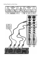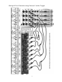
1
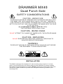
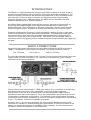
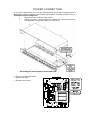
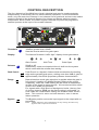
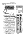
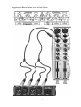
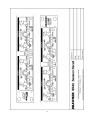
DRAWMER
MX40
QUAD PUNCH GATE
OPERATORS MANUAL
CONTENTS
SAFETY CONSIDERATIONS
page 3
INSTALLATION
page 3
INTRODUCTION
•
Audio Connections
•
Power Connection
page 4
page 4
page 5
CONTROL DESCRIPTIONS
•
Punch Gate
•
Key Filter
•
Linking
page
page
page
page
OPERATION
page 8
IF A FAULT DEVELOPS
CONTACTING DRAWMER
page 12
page 12
TECHNICAL SPECIFICATION
page 13
BLOCK DIAGRAM
page 14
SESSION RECALL
page 15
1
6
6
7
7
COPYRIGHT
This manual is copyrighted © 2011 by Drawmer Electronics, Ltd. With all rights
reserved. Under copyright laws, this manual may not be duplicated in whole
or in part without the written consent of Drawmer.
ONE YEAR LIMITED WARRANTY
Drawmer Electronics Ltd., warrants the MX40 Quad Punch Gate to conform
substantially to the specifications of this manual for a period of one year from
the original date of purchase when used in accordance with the specifications
detailed in this manual. In the case of a valid warranty claim, your sole and
exclusive remedy and Drawmer’s entire liability under any theory of liability will
be to, at Drawmer’s discretion, repair or replace the product without charge,
or, if not possible, to refund the purchase price to you. This warranty is not
transferable. It applies only to the original purchaser of the product.
For warranty service please call your local Drawmer dealer. Alternatively call
Drawmer Electronics Ltd. at +44 (0)1709 527574. Then ship the defective
product, with transportation and insurance charges pre-paid, to Drawmer
Electronics Ltd., Coleman Street, Parkgate, Rotherham, S62 6EL UK. Write
the RA number in large letters in a prominent position on the shipping box.
Enclose your name, address, telephone number, copy of the original sales
invoice and a detailed description of the problem. Drawmer will not accept
responsibility for loss or damage during transit.
This warranty is void if the product has been damaged by misuse, modification
or unauthorised repair.
THIS WARRANTY IS IN LIEU OF ALL WARRANTIES, WHETHER ORAL OR
WRITTEN, EXPRESSED, IMPLIED OR STATUTORY. DRAWMER MAKES
NO OTHER WARRANTY EITHER EXPRESS OR IMPLIED, INCLUDING,
W ITHOUT LIMITATION, ANY IMPLIED W ARRANTIES OF
MERCHANTABILITY, FITNESS FOR A PARTICULAR PURPOSE, OR NONINFRINGEMENT. PURCHASER’S SOLE AND EXCLUSIVE REMEDY UNDER
THIS WARRANTY SHALL BE REPAIR OR REPLACEMENT AS SPECIFIED
HEREIN.
IN NO EVENT WILL DRAWMER ELECTRONICS LTD. BE LIABLE FOR ANY
DIRECT, INDIRECT, SPECIAL, INCIDENTAL OR CONSEQUENTIAL
DAMAGES RESULTING FROM ANY DEFECT IN THE PRODUCT,
INCLUDING LOST PROFITS, DAMAGE TO PROPERTY, AND, TO THE
EXTENT PERMITTED BY LAW, DAMAGE FOR PERSONAL INJURY, EVEN
IF DRAWMER HAS BEEN ADVISED OF THE POSSIBILITY OF SUCH
DAMAGES.
Some states and specific countries do not allow the exclusion of implied
warranties or limitations on how long an implied warranty may last, so the
above limitations may not apply to you. This warranty gives you specific legal
rights. You may have additional rights that vary from state to state, and country
to country.
In the interests of product development, Drawmer reserve the right to modify
or improve specifications of this product at any time, without prior notice.
2
DRAWMER MX40
Quad Punch Gate
SAFETY CONSIDERATIONS
CAUTION - M AINS FUSE
TO REDUCE THE RISK OF FIRE REPLACE THE MAINS FUSE ONLY WITH
THE SAME TYPE, WHICH MUST BE A CLASS 3, 230 VOLT, TIME DELAY
TYPE, RATED AT 63mA WHERE THE MAINS INPUT VOLTAGE SWITCH IS
SET TO 230 VOLTS AC. AND 125mA WHERE THE MAINS INPUT VOLTAGE
IS 115 VOLTS AC.
ALL FUSES MUST COMPLY WITH IEC 127-2.
THE FUSE BODY SIZE IS 20mm x 5mm.
CAUTION - MAINS CABLE
DO NOT ATTEMPT TO CHANGE OR TAMPER WITH THE SUPPLIED MAINS
CABLE.
CAUTION - SERVICING
DO NOT PERFORM ANY SERVICING. REFER ALL SERVICING TO
QUALIFIED SERVICE PERSONNEL.
WARNING
TO REDUCE THE RISK OF FIRE OR ELECTRIC SHOCK DO NOT EXPOSE
THIS EQUIPMENT TO RAIN OR MOISTURE.
INSTALLATION
The MX40 is designed for standard 19" rack mounting and occupies 1U of rack
space. Avoid mounting the unit directly above power amplifiers or power supplies
that radiate significant amounts of heat. Always connect the mains earth to the unit.
Use fibre or plastic washers to prevent the front panel becoming marked by the
mounting bolts.
3
INTRODUCTION
The MX40 is a highly flexible but compact quad Gate suitable for a wide range of
professional applications including studio, live sound and audio installations. The
input and output connections are electronically balanced on XLR connectors and
low-distortion VCAs are used to maintain the highest possible signal quality.
Although optimised for +4dBu operation, the MX40 will work equally well with
systems operating at the -10dBu standard.
Any Noise Gate considerably improves the sound of percussive instruments by
producing fast leading edges to the signal and then shutting off after a predetermined time. The combination of this fast rising edge, and the silence which
follows the gated signal, creates a dramatic improvement to the original signal.
Drawmer pioneered the frequency conscious gating common to many noise gate
clones now available in audio processing equipment. The MX40 has a new spin on
this feature where both controls have been amalgamated into a single intuitive
control, of course with a Key Listen facility. This allows fast and simple setup of
frequency selective triggering where unwanted signals are prevented from triggering
the gate.
AUDIO CONNECTIONS
Input and Output audio connections are provided via balanced XLRs at a level of
+4dBu. This applies to both inputs and outputs. The wiring convention being:
Pin 1 Ground;
Pin 2 Hot(+);
and Pin 3 Cold(-).
For use with unbalanced systems, the Cold pin 3 must be grounded at both input and
output inside the XLR connectors. For connection to a patch bay, input sockets
should be wired ‘fully normalised’.
The key input is an unbalanced ¼" (TRS) jack socket. For connection to a patch bay
this socket should be wired ‘fully normalised’ to prevent erratic triggering.
Interference: If the unit is to be used where it maybe exposed to high levels of
disturbance such as found close to a TV or radio transmitter, we advise that the unit
is operated in a balanced configuration. The screens of the signal cables should be
connected to the chassis connection on the XLR connector as opposed to connecting
to pin1. The MX40 conforms to the EMC standards.
Ground Loops: If ground loop problems are encountered, never disconnect the
mains earth, instead, try disconnecting the signal screen on one end of each of the
cables connecting the outputs of the MX40 to the patchbay. If such measures are
necessary, balanced operation is recommended.
4
POWER CONNECTION
If, for some reason, the unit is to be operated at a mains input voltage which is
different to that as supplied, the following procedure must be carried out by a
qualified technical engineer.
1:
Disconnect the unit from the mains.
2:
Using a number 1 size pozidrive screwdriver, remove the seven
self-tapping screws that retain the top cover.
Accessing the internal power switch and fuse
3. Set the voltage rating and
replace the fuse.
4. Replace the cover.
5
CONTROL DESCRIPTION
The four channels of the MX40 are virtually identical and may be used completely
independently or linked as pairs for stereo-channel operation. In the linked stereo
mode, only the controls of channel 1 and channel 3 are functional and serve as master
controls, though all the channel Bypass, Key Listen and Range switches remain
independent. W hen linked, the control signal is derived only from the programme
material present at the input of the master channel.
Threshold
-60dB to greater than +20dB
Sets the level at which the gate opens.
Display
The famous Drawmer “traffic light” display shows gate status.
Gate Closed
Hold Time
Gate Open
Release
25mS to 4S.
Additionally some envelope hold time is built into the system
which varies with the release time setting.
Peak Punch
Peak Punch is a dynamic feature which accelerates the leading
edge as the gated signal opens, adding more than 6dB of gain for
approximately 10mS with proprietary release characteristics.
Range
Determines how much gain reduction is applied when the gate is
fully closed. A setting of -90dB effectively silences the signal
completely, while the -20dB setting will still allow an attenuated
version of the signal to pass through. We recommend this switch
is left in the -90dB (out) position.
For signals with a high levels of background noise, the very fact
of closing down to -90dB can be disconcertingly noticeable. In
such cases the -20dB switch setting can achieve better results.
Note: This control is active on both channels, even in stereo
linked operation.
Bypass
The Bypass position routes the input signal to the output with no
processing.
N o te :
T h e s e s w itc h e s a re in d e p e n d e n t o f a n y lin k in g a n d w ill o n ly
b y p a s s th e ir re s p e c tive c h a n n e l.
6
Key Filter
Key Listen
In normal operation, the filter only affects the way the MX40
responds to the incoming programme material - it does not have
any direct effect on the output signal, but when Key listen is
enabled, the effect of the key filter on the programme material is
heard at the output. These switches are independent of any
linking and enable Key Listen of only their respective channel.
Trigger Freq.
50Hz to 8KHz with a width (or ‘Q’) of one octave.
Use Key Filter to hear the filter, and tune into the loudest part of
the trigger source sound.
Ext Key
When in the Ext(ernal) Key position, the LED will be illuminated
and the common external key source buss is used to control the
gate action, making it possible to gate one sound according to the
signal dynamics of another, independent signal. If released, this
switch causes the gate to respond to the dynamics of the signal
present at the channel signal input socket.
If no Ext Key input is plugged into the unit, then Channel 1's
audio signal becomes the default trigger source available to all
channels selected by the Key Input.
Filter In
This switch is used to enable the control of the key trigger filter. It
is normal that this switch would be selected except where the
internal (or external) control signal has a broad spectrum of audio
information that the narrow pass-band of the filter would
otherwise restrict trigger information.
Linking
Slave Link
The Link buttons are located between odd/even channels, and
when depressed, cause the channel on the right (channel 2 or 4)
to be controlled by the left-hand channel (channel 1 or 3). In
linked mode, the red status LED beneath the Slave Link switch
will be illuminated, and the Ext Key and Peak Punch LEDs of the
slave channel will be extinguished. This indicates which controls
of the slave channel are still operative.
7
OPERATION
Use the following diagrams as a guide to using the MX40.
Typical Setup
8
Triggering a Bass Guitar from a Kick Drum
9
Adding Depth to a Kick Drum
10
Gating all Four Channels using Channel 1 as the Trigger
11
IF A FAULT DEVELOPS
For warranty service please call Drawmer Electronics Ltd. Or their nearest authorised
service facility, giving full details of the difficulty. On receipt of this information,
service or shipping instructions will be forwarded to you. No equipment should be
returned under the warranty without prior consent from Drawmer or their authorised
representative.
For service claims under the warranty agreement a service Returns Authorisation
(RA) number will be given. W rite this RA number in large letters in a prominent
position on the shipping box. Enclose your name, address, telephone number, copy of
the original sales invoice and a detailed description of the problem.
Authorised returns should be prepaid and must be insured. All Drawmer products are
packaged in specially designed containers for protection. If the unit is to be returned,
the original container must be used. If this container is not available, then the
equipment should be packaged in substantial shock-proof material, capable of
withstanding the handling for the transit.
CONTACTING DRAWMER
Drawmer Electronics Ltd., will be pleased to answer all application questions to
enhance your usage of this equipment. Please address correspondence to:
Drawmer (Technical Help line) : Coleman St.: Parkgate : Rotherham : S62 6EL : UK
or, E-mail us on :
[email protected]
Drawmer dealers, Authorised service departments and other contact information can
be obtained from our web pages on
http://www.drawmer.com
12
TECHNICAL SPECIFICATIONS
(All measurements reference +4dBu operating level)
INPUT IMPEDANCE
20KÙ (Balanced)
KEY INPUT IMPEDANCE
20KÙ (Unbalanced)
INPUT CMR
>-40dB
MAXIMUM INPUT LEVEL
+21dBu
MAXIMUM KEY INPUT LEVEL
+21dBu
OUTPUT IMPEDANCE
50Ù (Balanced)
MAXIMUM OUTPUT LEVEL
+21dBu
BANDWIDTH
<10Hz to 22KHz -1dB
NOISE
Wideband
(worst case)
22Hz - 22KHz
AV
-100dB
-105dB
RMS
-104dB
-106dB
DISTORTION
Gate Open with +4dBu input
100Hz
1KHz
10KHz
< 0.04%
< 0.02%
< 0.04%
POWER REQUIREMENTS
115Volt or 230Volt at 50-60Hz, 15 W atts
FUSE RATING
63mA for 230Volt, 125mA for 115Volt
CONFORMING TO IEC 127-2
FUSE TYPE
20mm x 5mm, Class 3 Slo-Blo, 250Volt working
CASE SIZE
482mm (w) x 44mm (h) x 175mm (d)
WEIGHT (incl packaging)
3.7 Kgs
13
BLOCK DIAGRAM
14
15
16