1
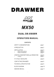
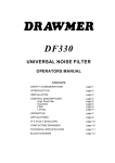
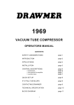
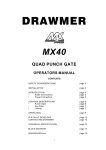
MULTI-CHANNEL
SURROUND DYNAMICS
OPERATORS MANUAL
CONTENTS
SAFETY CONSIDERATIONS
page 1
INTRODUCTION
page 2
INSTALLATION
page 2
POWER CONNECTION
Page 2
AUDIO CONNECTIONS
Page 3
CONTROL DESCRIPTIONS
page 5
OPERATION
page 8
IF A FAULT DEVELOPS
page 10
CONTACTING DRAWMER
page 10
TECHNICAL SPECIFICATION
page 11
BLOCK DIAGRAM
page 12
i
COPYRIGHT
This manual is copyrighted © 2001 by Drawmer Electronics, Ltd. With all rights
reserved. Under copyright laws, this manual may not be duplicated in whole or
in part without the written consent of Drawmer.
ONE YEAR LIMITED WARRANTY
Drawmer Electronics Ltd., warrants the Drawmer “Six-Pack” audio processor to
conform substantially to the specifications of this manual for a period of one year
from the original date of purchase when used in accordance with the
specifications detailed in this manual. In the case of a valid warranty claim, your
sole and exclusive remedy and Drawmer’s entire liability under any theory of
liability will be to, at Drawmer’s discretion, repair or replace the product without
charge, or, if not possible, to refund the purchase price to you. This warranty is
not transferable. It applies only to the original purchaser of the product.
For warranty service please call your local Drawmer dealer. Alternatively call
Drawmer Electronics Ltd. at +44 (0)1709 527574. Then ship the defective product,
with transportation and insurance charges pre-paid, to Drawmer Electronics Ltd.,
Coleman Street, Parkgate, Rotherham, S62 6EL UK. Write the RA number in large
letters in a prominent position on the shipping box. Enclose your name, address,
telephone number, copy of the original sales invoice and a detailed description
of the problem. Drawmer will not accept responsibility for loss or damage during
transit.
This warranty is void if the product has been damaged by misuse, modification
or unauthorised repair.
THIS WARRANTY IS IN LIEU OF ALL WARRANTIES, WHETHER ORAL OR
WRITTEN, EXPRESSED, IMPLIED OR STATUTORY. DRAWMER MAKES NO OTHER
WARRANTY EITHER EXPRESS OR IMPLIED, INCLUDING, WITHOUT LIMITATION,
ANY IMPLIED WARRANTIES OF MERCHANTABILITY, FITNESS FOR A
PARTICULAR PURPOSE, OR NON-INFRINGEMENT. PURCHASER’S SOLE AND
EXCLUSIVE REMEDY UNDER THIS WARRANTY SHALL BE REPAIR OR
REPLACEMENT AS SPECIFIED HEREIN.
IN NO EVENT WILL DRAWMER ELECTRONICS LTD. BE LIABLE FOR ANY DIRECT,
INDIRECT, SPECIAL, INCIDENTAL OR CONSEQUENTIAL DAMAGES RESULTING
FROM ANY DEFECT IN THE PRODUCT, INCLUDING LOST PROFITS, DAMAGE TO
PROPERTY, AND, TO THE EXTENT PERMITTED BY LAW, DAMAGE FOR
PERSONAL INJURY, EVEN IF DRAWMER HAS BEEN ADVISED OF THE
POSSIBILITY OF SUCH DAMAGES.
Some states and specific countries do not allow the exclusion of implied
warranties or limitations on how long an implied warranty may last, so the above
limitations may not apply to you. This warranty gives you specific legal rights.
You may have additional rights that vary from state to state, and country to
country.
In the interests of product development, Drawmer reserve the right to modify or
improve specifications of this product at any time, without prior notice.
ii
SIX-PACK” OPERATORS’ MANUAL
1
DRAWMER Six-Pack
Multi-Channel
Surround Dynamics
SAFETY CONSIDERATIONS
CAUTION - MAINS FUSE
TO REDUCE THE RISK OF FIRE REPLACE THE MAINS FUSE ONLY WITH A
FUSE THAT CONFORMS TO BS EN 60127-2:1991 SHEET III. 250 VOLT
WORKING, TIME DELAY TYPE AND BODY SIZE OF 20mm x 5mm.
THE MAINS INPUT FUSE MUST BE RATED AT T500mA. .
CAUTION - MAINS CABLE
DO NOT ATTEMPT TO CHANGE OR TAMPER WITH THE SUPPLIED MAINS
CABLE.
CAUTION - SERVICING
DO NOT PERFORM ANY SERVICING. REFER ALL SERVICING TO QUALIFIED
SERVICE PERSONNEL.
WARNING
TO REDUCE THE RISK OF FIRE OR ELECTRIC SHOCK DO NOT EXPOSE THIS
EQUIPMENT TO RAIN OR MOISTURE.
2
“SIX-PACK” OPERATORS’ MANUAL
INTRODUCTION
The Drawmer SixPack is a six channel Expander/Compressor/Limiter with extensive
linking facilities which allow for the various configurations commonly used in
multi-channel surround processing as well as the more conventional stereo and
single channel operation.
Each channel has a program adaptive expander, with variable threshold and
release times, followed by a soft knee compressor with optional auto attack
and release as well as the normal manual controls. A variable threshold,
zero-overshoot limiter provides total protection against even the fastest
transients and is particularly valuable in live sound applications for driver
protection.
An optional 125Hz filter on channel 6 may be used to create the LFE channel
from a 5-1 mono mix.
Each channel of the SixPack has balanced XLR inputs and outputs, with relay
hard wire bypass, so signals still pass through the unit when the power is off.
Powered by a universal switch mode power supply, the SixPack operates from
mains voltages between 85 - 250v, eliminating the need to make any changes
when touring and allowing the unit to remain fully operational during large
fluctuations in the mains power supply.
INSTALLATION
The “Six-Pack” is designed for standard 19" rack mounting and occupies 3U of rack
space. Avoid mounting the unit directly above power amplifiers or power supplies
that radiate significant amounts of heat. Fibre or plastic washers may be used to
prevent the front panel becoming marked by the mounting bolts.
POWER CONNECTION
The unit will be supplied with a power cable suitable for domestic power outlets in
your country. For your own safety it is important that you use this cable. The unit
should always be connected to the mains supply earth using this cable
Powered by a universal switch mode power supply, the SixPack operates from
mains voltages between 85 - 250v, eliminating the need to make any changes
when touring and allowing the unit to remain fully operational during large
fluctuations in the mains power supply.
SIX-PACK” OPERATORS’ MANUAL
3
AUDIO CONNECTIONS
Both the input and output connectors may be used either balanced or unbalanced,
the wiring convention for XLR connectors being: pin 2 hot, pin 3 cold and pin 1
ground. Unbalanced operation is achieved by shorting pin 3 of the XLR connector
to ground (pin 1) at both input and output.
Interference:
If the unit is to be used where it maybe exposed to high levels
of disturbance such as found close to a TV or radio transmitter,
we advise that the unit is operated in a balanced configuration.
The screens of the signal cables should be connected to the
chassis connection on the XLR connector as opposed to
connecting to pin1. The “Six-Pack” conforms to the EMC
standards.
Ground Loops:
If ground loop problems are encountered, never disconnect the
mains earth, but instead, try disconnecting the signal screen on
one end of each of the cables connecting the outputs of the SixPack to the patchbay. If such measures are necessary, balanced
operation is recommended.
4
“SIX-PACK” OPERATORS’ MANUAL
Connecting the Six-Pack to a 5.1 Surround Mixing Desk
SIX-PACK” OPERATORS’ MANUAL
5
CONTROL DESCRIPTION
All six channels of the “Six-Pack” are identical and may be used completely
independently or linked for 5.1 surround operation.
EXPANDER
Threshold:
Range -70dB to +20dB.
This control sets the level below which expansion starts
to take place. When the expander starts to operate, the
red status LED will come on. Note: because the expansion
ratio varies with signal level, it is possible to arrive at a
situation where the red expansion LED may be illuminated
when little or no perceived gain reduction is taking place.
This means that the expansion Threshold may need to be
set a little higher than it would with a conventional
expander and final setting is best done by ear. The adaptive expansion system used
in the “Six-Pack” means, however, that setting up is not over-critical and the gating
action is far more progressive.
Release:
A release time of between 0.05 to 1 Second may be selected depending
on the material being processed. Percussive material with little or no
reverb is generally treated using a faster release setting, whereas
material with slow decays or a significant amount of added
reverberation will usually respond better to a longer release setting.
COMPRESSOR
Threshold:
Determines the input level above which
gain reduction will be applied and may be
set in the range -40 to +20dB. Soft knee
compression takes place for signals
exceeding the threshold level by up to 10dB
above which level, conventional 'ratio'
compression is applied.
Ratio:
Sets the final compression ratio that will be
applied once the 10dB 'soft-knee' region is
exceeded. The ratio may be continuously
adjusted from 1.2:1 to infinity:1 allowing
the possibility of true hard limiting.
Release:
Sets the rate at which the system gain returns to normal after the input
signal level has fallen below the threshold. This may be set in the range
0.05 seconds to 5 seconds.
Attack:
Sets the rate at which the compressor will respond to input signals that
exceed the threshold level. This may be set in the range 0.5mS to
100mS.
6
“SIX-PACK” OPERATORS’ MANUAL
Auto:
When selected, Auto disables the Attack and Release controls and
continually optimises the attack and release times to suit the d
of the material being processed. In general, this setting will produce
the least obtrusive level control on signals with widely varying
dynamics or complete mixes.
Gain:
The output level may be attenuated or amplified by up to 20dB to
compensate for level changes caused by compression and limiting.
This control comes before the Peak limiter detector and this fact
should be taken into account when setting the Peak limiter threshold.
Gain Reduction
Meter:
An eight segment LED bargraph meter continuously monitors the gain
reduction applied by the compressor/limiter over the range 0 to 30dB.
Output
Level Meter This is an 8 segment LED bargraph level meter that monitors the level
of the output signal over the range -20dB to +15dB.
Bypass:
This switch causes a 'hard-wire' bypass function of all signal
processing for this channel, where the input socket is routed directly
to the output socket. This feature enables the unit to pass audio even
with no power applied to the “Six-Pack”. Normally the switch is used
to compare the raw unprocessed signal verses with any expansion,
compression and limiting of the audio input.
When in bypass the level metre shows the unmodified input signal
coming into that particular channel.
PEAK LIMITER
Level:
Sets an absolute limit to the level that the output signal will not
be permitted to exceed. This limiter is very fast acting enabling
it to control any peaks without audible distortion. If the output
signal is so high as to cause the limiter to operate for more than
20mS, the system gain is automatically reduced to bring the
signal back within range. The system gain is then returned to
normal over a period of approximately one second. The
compressor Gain control should be used to ensure that the peak
limiter operates only rarely if at all, if it is to be used purely for
peak protection. Alternatively, it may be deliberately driven into
limiting to produce creative effects. The red LED comes on
when the limiter is active.
SIX-PACK” OPERATORS’ MANUAL
7
LINKING
Link:
Pressing the link switch on any channel causes it to
be linked to and completely controlled from, the
previous channel (to the left). Therefore, pressing
link on channel 2, will link channels 1 and 2, with
channel 1 being the master channel. In addition,
pressing link on channels 2 and 3 will link channels
1,2 and 3 with channel 1 being the master.
All channels show Master or Linked status.
Channel 1 is always a master channel.
The following diagram shows the more commonly used linking configurations:
8
“SIX-PACK” OPERATORS’ MANUAL
OPERATION
The unit should be connected in line with the signal to be processed via suitable
insert points. For single channel use, each channel may be considered as being
completely independent and set up accordingly. For use with stereo or multichannel signals such as complete mixes or submixes, the unit should be switched
to Link mode and all setting up done using the master channel controls.
Setting up is simpler if the Expander is initially turned off and the Peak Limiter
threshold set to maximum. This allows the Compressor/Limiter to be set up in
isolation. The ratio setting depends on how firmly the signal dynamics need
controlling; as a rule, higher ratios provide a higher degree of control but also tend
to be more audible in operation when high levels of gain reduction are required. The
integral soft-knee feature of the “Six-Pack” renders these effects far less
pronounced, but this factor should still be taken into consid
In general, a higher compression ratio may be used than on a conventional
compressor without compromising the sound quality.
If the Attack and Release controls are switched to Auto, setting up is now simply a
matter of adjusting the Threshold control until the desired amount of gain reduction
occurs. This is judged partly by ear and partly by observing the gain reduction
meter. In general, a maximum gain reduction of between 8dB and 12dB will be
adequate. If more gain reduction appears necessary, consider applying a
conservative degree of compression during recording and then further compression
while mixing.
Compressing during a mix does increase the subjective level of tape and other
background noises during pauses and quiet passages but, unless the noise
contamination is serious, the expander section will be able to attenuate it to a very
high degree without compromising the wanted signal.
At this point, the Auto control may be switched off if it is desired to set the attack
and release times manually. The longer the attack time, the longer the compressor
takes to respond to increases in signal level and a slow attack time is often used to
accentuate the beginning of percussive or plucked sounds such as drums, basses
and guitars. A fast attack time will bring the input signal under control very quickly.
The release time should be set short enough so that the system gain has returned
to normal before the next peak occurs and, in general, it should be set as short as
possible before audible gain pumping occurs.
At this point, the expander threshold may be set up and you should adjust the
release time settings to the least obtrusive in operation. For all but sharp percussive
sounds, a longer setting is likely to give the best results. Set the threshold using a
piece of program material that contains pauses and adjust the threshold to be as low
a dB level as possible while still attenuating the noise during pauses. Listen carefully
to how the sounds come in after the pauses and how cleanly they fade away again.
If you can hear the expander changing the sound in an unacceptable way, then the
threshold is probably set too high.
Because the expander is self-adapting to the programme dynamics, it should be
possible to obtain far more satisfactory results than are possible with conventional
expanders. By the same token, do not assume that because the expander threshold
SIX-PACK” OPERATORS’ MANUAL
9
LED flickers during a piece of quiet but wanted material that it is having a detrimental
i
effect. When it first comes
ears!
Finally, set the Gain control to give the required output level using the level meter
to guide you. Av o i d r u n n i n g a t v e r y h i g h o u t p u t l e v e l s a s t h i s r e d u c e s t h e a v a i l a b
amount of signal head room and could lead to distortion in extrem e c a s e s . O n c e t h e
gain is correct, set the Peak Limiter Level control so that the limiter LED only lights
briefly on extreme signal peaks. Alternatively, set the Peak limiter Level to the
desired value and then adjust the compressor Gain control to ensure minimum
limiter activity.
If required, the expander may be used on its own with the compressor and limiter
functions disabled. The Peak limiter has no sep
Level control fully clockwise will prevent any unwanted limiter
bypass the compressor section turn the compressor Threshold up to its maximum
of +20dB (fully counter-clockwise), set the Ratio to its lowest setting of 1.2:1 and
adjust the Gain to approximately 0dB.
10
“SIX-PACK” OPERATORS’ MANUAL
IF A FAULT DEVELOPS
For warranty service please call Drawmer Electronics Ltd. Or their nearest authorised
service facility, giving full details of the difficulty. On receipt of this information,
service or shipping instructions will be forwarded to you. No equipment should be
returned under the warranty without prior consent from Drawmer or their authorised
representative.
For service claims under the warranty agreement a service Returns Authorisation
(RA) number will be given. Write this RA number in large letters in a prominent
position on the shipping box. Enclose your name, address, telephone number, copy
of the original sales invoice and a detailed description of the problem.
Authorised returns should be prepaid and must be insured. All Drawmer products
are packaged in specially designed containers for protection. If the unit is to be
returned, the original container must b
the equipment should be packaged in substantial shock-proof material, capable of
withstanding the handling for the transit.
CONTACTING DRAWMER
Drawmer Electronics Ltd., will be pleased to answer all application questions to
enhance your usage of this equipment. Please address correspondence to:
Drawmer (Technical Help line) : Coleman St.: Parkgate : Rotherham : S62 6EL : UK
or, E-mail us on :
[email protected]
Drawmer dealers, Authorised service departments and other contact information can
be obtained from our web pages on
http://www.drawmer.co.uk
SIX-PACK” OPERATORS’ MANUAL
11
TECHNICAL SPECIFICATIONS
(Measurements taken at +4dBu operating level where applicable)
INPUT IMPEDANCE
20K S
MAXIMUM INPUT LEVEL
+20dBu
OUTPUT IMPEDANCE
50 S (bal), 100 S (unbal)
MAXIMUM OUTPUT LEVEL
+20dBu
BANDWIDTH
<10Hz to 22KHz -1dB
NOISE AT UNITY GAIN with Expander Off
Wideband
22Hz - 22KHz
CCIR ARM
IEC A
Q-Pk CCIR
AV
-90dB
-95dB
-95dB
-97dB
-84dB
RMS
-88dB
-93dB
-93dB
-95dB
-82dB
DISTORTION
Unity Gain, +4dBu input
+14dBu input, 10dB Gain Red.
100Hz
1KHz
10KHz
< 0.03%
< 0.02%
<0.03%
< 0.1%
< 0.1%
< 0.1%
POWER REQUIREMENTS
115Volt or 230Volt at 50-60Hz, 9 Watts
FUSE RATING
32mA for 230Volt,
63mA for 115Volt
CONFORMING TO BS EN 60127-2:1991 SHEET III
FUSE TYPE
20mm x 5mm, Class 3 Slo-Blo, 250Volt working
CASE SIZE
482mm (w) x 44mm (h) x 200mm (d)
WEIGHT (incl packaging)
3.2 Kgs
12
“SIX-PACK” OPERATORS’ MANUAL
BLOCK DIAGRAM