1
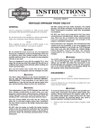
Table of Contents 175XR2 Jet Drive Installation Manual Page General Information . . . . . . . . . . . . . . . . . . . . . . . . . 2 Notice to Installer . . . . . . . . . . . . . . . . . . . . . . . . . 2 Installation Products . . . . . . . . . . . . . . . . . . . . . 2 Torque Specifications . . . . . . . . . . . . . . . . . . . . . 2 Serial Number Decal Location . . . . . . . . . . . . . . 3 Corrosion Protection . . . . . . . . . . . . . . . . . . . . . . 3 Installation Requirements . . . . . . . . . . . . . . . . . . . . 3 Battery/Battery Cables . . . . . . . . . . . . . . . . . . . . 3 Boat Construction . . . . . . . . . . . . . . . . . . . . . . . . 4 Engine Compartment Ventilation . . . . . . . . . . . . 4 Exhaust System . . . . . . . . . . . . . . . . . . . . . . . . . . 4 Fuel Delivery System . . . . . . . . . . . . . . . . . . . . . 5 Instrumentation . . . . . . . . . . . . . . . . . . . . . . . . . . . 5 Wiring Diagrams . . . . . . . . . . . . . . . . . . . . . . . . . . 6 Impeller Selection . . . . . . . . . . . . . . . . . . . . . . . . 7 Remote Control and Cables . . . . . . . . . . . . . . . . 7 Steering Helm and Cable . . . . . . . . . . . . . . . . . . 7 Mercury Jet Drive Hull Dimensions 175XR2 . . . . . 8 Installing Jet Pump . . . . . . . . . . . . . . . . . . . . . . . . . 10 Steering Cable Adjustment . . . . . . . . . . . . . . . . 12 Shift Cable Adjustment . . . . . . . . . . . . . . . . . . . 13 Bilge Siphon Feature . . . . . . . . . . . . . . . . . . . . . . . 15 Installing Bilge Siphon . . . . . . . . . . . . . . . . . . . . 15 Water By-Pass System . . . . . . . . . . . . . . . . . . . . . 15 Installing Powerhead . . . . . . . . . . . . . . . . . . . . . . . 16 Battery Connection . . . . . . . . . . . . . . . . . . . . . . 17 Throttle Cable Adjustment . . . . . . . . . . . . . . . . 18 Oil Injection System . . . . . . . . . . . . . . . . . . . . . . 18 Bleeding Air from Oil Injection Pump . . . . . . . 19 Adjusting Oil Injection Pump . . . . . . . . . . . . . . 19 Turn-Key Start Feature . . . . . . . . . . . . . . . . . . . . . . 20 Trim Plate Adjustment . . . . . . . . . . . . . . . . . . . . . . 20 Pre-delivery Inspection . . . . . . . . . . . . . . . . . . . . . . 21 NOTICE to COMMISSIONING DEALER Pre-delivery Preparation Instructions Must Be Performed Before Delivering Boat to the Product Owner. NOTICE to INSTALLER After Completing Installation, These Instructions Should Be Placed with the Product for the Owner’s Future Use. NOTICE to INSTALLER The United States Coast Guard does not have a method to determine the maximum recommended horsepower for Inboard Jet Boats. Therefore, it is the responsibility of the boat manufacturer to install the Mercury Jet Drive, as well as any other Jet Drive model, in a boat which has been determined to be of suitable size, weight, construction, and hull configuration for the power chosen. The Mercury Jet Drive, in particular, brings a new level of performance to the jet boat category and is capable of propelling many hulls at speeds exceeding 50 miles per hour. In selecting the proper Jet Drive package for a particular application, please consider the overall performance capability of the craft. Your boat may react to and handle differently with each Jet Drive model. PLEASE carefully test and evaluate the overall handling characteristics of the boat package before distribution for sale. If you have application or installation questions, please contact your Mercury Marine OEM Sales Coordinator. The Sales Coordinator will arrange to provide the necessary assistance. Please assess your boat’s performance completely before making the Jet Drive model selection. Safe boating is good for everyone. 2003 Mercury Marine The following are registered trademarks of Brunswick Corporation: AutoBlend, Force, Jet-Prop, Mariner, Merc, MerCathode, MerCruiser, Mercury, Mercury Marine, Quicksilver, RideGuide, Sport Jet, and Thruster. Printed in U.S.A. -1- 90-10164040 1203 We could not possibly know of and advise the marine trade of all conceivable procedures by which an installation might be performed and of the possible hazards and/or results of each method. We have not undertaken any such wide evaluation. Therefore, anyone who uses an installation procedure and/or tool, which is not recommended by the manufacturer, first must completely satisfy himself that neither his nor the product’s safety will be endangered by the installation procedure selected. General Information Notice to Installer Throughout this publication, Warnings and Cautions (accompanied by the International Hazard Symbol) are used to alert the installer to special instructions concerning a particular service or operation that may be hazardous if performed incorrectly or carelessly. –– Observe Them Carefully! All information, illustrations, and specifications contained in this manual are based on the latest product information available at time of publication. As required, revisions to this manual will be sent to all OEM boat companies. These Safety Alerts, alone, cannot eliminate the hazards that they signal. Strict compliance to these special instructions when performing the service, plus common sense operation, are major accident prevention measures. ! INSTALLATION PRODUCTS ! WARNING Loctite 271 Liquid Neoprene Dielectric Grease Perfect Seal Special Lube 101 Hazards or unsafe practices which COULD result in severe personal injury or death. ! CAUTION 92-823089--1 92-25711--2 92-823506--1 92-34227--1 92-13872A1 Hazards or unsafe practices which could result in minor personal injury or product or property damage. Torque Specifications IMPORTANT: Indicates information or instructions that are necessary for proper installation and/or operation. 10 mm Fasteners (Powerhead to Pump) 47 Nm (35 lb. ft) Reverse Stop Screw 14 Nm (120 lb. in.) Forward Stop Screw 14 Nm (120 lb. in.) Ride Plate to Pump Screws 8.5 Nm (75 lb. in.) NOTE: Tighten all fasteners, not listed, securely. This installation manual has been written and published by the service department of Mercury Marine to aid installers when installing the products described herein. It is assumed that these personnel are familiar with the installation procedures of these products, or like or similar products manufactured and marketed by Mercury Marine. Also, that they have been trained in the recommended installation procedures of these products which includes the use of mechanics’ common hand tools and the special Mercury Marine or recommended tools from other suppliers. Drive Housing Cover to Drive Housing fasteners 47 Nm (35 lb. ft.) -2- Serial Number Decal Location Corrosion Protection A serial number decal is located on the side of the flywheel cover and on top of the cylinder block. This power package is equipped with anodes to help protect it from galvanic corrosion under moderate conditions. See the Operator’s Manual for location of anodes. a OGXXXXXX 19XX Installation Requirements b OGXXXXXX d XX IMPORTANT: The Jet Drive is considered an INBOARD engine. The boat it is installed in must meet industry standards (ABYC, NMMA, etc.), federal standards and Coast Guard regulations for INBOARD engine installations c Battery/Battery Cables IMPORTANT: Boating industry standards (ABYC, NMMA, etc.), federal standards and Coast Guard regulations must be adhered to when installing battery. Be sure battery cable installation meets the pull test requirements and that positive battery terminal is properly insulated in accordance with regulations. 28238 a b c d - Engine Serial Number Model Year Year Manufactured Certified Europe IMPORTANT: Engine electrical system is negative (–) ground. It is recommended (required in some states) that battery be installed in an enclosed case. Refer to regulations for your area. IMPORTANT: The Pump Unit Serial Number sticker must be taken out of the envelope affixed to the pump unit and applied to the flywheel cover decal. 1. Select a battery that meets all of the following specifications: The engine serial number and pump serial number are different and unique. The engine serial number is located aft of the flywheel cover. The pump unit serial number is stamped in a plug located above the shift cable hole on the starboard side of the pump housing. a. 12-volt marine type. b. 670 Marine Cranking Amps (MCA) or 520 Cold Cranking Amps (CCA) minimum. c. Reserve capacity rating of at least 100 minutes. e 2. Select proper size positive (+) and negative (–) battery cables using chart. Battery should be located as close to engine as possible. 175 IMPORTANT: Terminals must be soldered to cable ends to ensure good electrical contact. Use electrical grade (resin flux) solder only. Do not use acid flux solder, as it may cause corrosion and a subsequent failure. Cable Length Up to 1.1 m (3-1/2 ft) 1.1 - 1.8 m (3-1/2 - 6 ft) 1.8-2.3 m (6 - 7-1/2 ft) 2.3-2.9 m (7-1/2 - 9-1/2 ft) 2.9-3.7 m (9-1/2 - 12 ft) 3.7- 4.6 m (12 - 15 ft) 4.6 - 5.8 m (15 - 19 ft) 28237 e - Pump Unit Serial Number -3- Cable Gauge 4 (25mm2) 2 (35mm2) 1 (50mm2) 0 (50mm2) 00 (70mm2) 000 (95mm2) 0000 (120mm2) Boat Construction Exhaust System IMPORTANT: All applicable U.S. Coast Guard regulations for INBOARD engines must be complied with, when constructing engine compartment. IMPORTANT: It is the responsibility of the boat manufacturer, or installing dealer, to properly locate the engine. Improper installation may allow water to enter the exhaust manifold and combustion chambers and severely damage the engine. Damage caused by water in the engine will not be covered by Mercury Marine Limited Warranty, unless this damage is the result of defective part(s). Care must be exercised in the design and construction of the engine compartment. Seams must be located so that any rain water or splash, which may leak through the seams, is directed away from the engine and carburetor cover. Also, the passenger compartment drainage system should not be routed directly to the engine compartment. Water that runs on or is splashed in the carburetor cover may enter the engine and cause serious damage to internal engine parts. The engine must be properly located to ensure that water will not enter the engine through the exhaust system. Determine the correct engine height by taking measurements (a) and (b), with boat at rest in the water and maximum load aboard. Subtract (b) from (a) to find (c). If (c) is less than specified in chart, boat construction must be altered to properly lower waterline relative to exhaust elbow. IMPORTANT: Mercury Marine will not honor any warranty claim for engine damage as a result of water entry. Engine Compartment Ventilation Engine compartment must be designed to provide a sufficient volume of air for engine breathing and also must vent off any fumes in engine compartment in accordance with industry standards (ABYC, NMMA, etc.), federal standards and U.S. Coast Guard regulations for inboard engines. Pressure differential (outside engine compartment versus inside engine compartment) should not exceed 51 mm (2 in.) of water (measured with a manometer) at maximum air flow rate. b a c d Engine Compartment Specifications Model 175XR2 Engine Air Requirements at Wide Open Throttle Physical Engine Volume* 487 ft.3/min. (0.230 m3/sec.) 1.33 ft.3 (38 L) a b c d - From Waterline to Top of Transom From Highest Point on Exhaust Manifold to Top of Transom (a) minus (b) = (c) Waterline at Rest (at Maximum Load) Model * Physical engine volume is used in flotation calculations and is representative of the amount of flotation the engine provides. 175XR2 For serviceability, it is recommended that an additional 152 mm (6 in) minimum (per side) of clearance be allowed between powerhead and engine compartment walls. -4- c = (a) minus (b) (c) must be 203 mm (8 in.) or more. Fuel Delivery System Instrumentation ! CAUTION ! WARNING Boating standards (NMMA, ABYC, etc.), federal standards and U. S. Coast Guard regulations for INBOARD engines must be adhered to when installing fuel delivery system. Failure to comply could result in severe personal injury or death. If a fused accessory panel is to be used, it is recommended that a separate circuit (properly fused) be used from the battery to the fuse panel with sufficient wire size to handle the intended current load. NOTE: The charging system on these engines is capable of producing 12 amps maximum charge at 3500 RPM. The electrical load of the boat should not exceed this capacity. ! CAUTION Remove plastic plug from fuel inlet fitting. Attach fuel line to fuel fitting with U.S. Coast Guard approved hose clamp. Inspect for fuel leaks. We recommend the use of Mercury Precision or Quicksilver Instrumentation and Wiring Harnesses. Refer to Mercury Precision Parts Accessories Guide for selection. 1. Fuel tank should be mounted below carburetor level (if possible) or gravity feed may cause carburetor fuel inlet needles to unseat, and flooding may result. If other than Mercury Precision or Quicksilver electrical accessories are to be used, it is good practice to use waterproof ignition components (ignition switch, lanyard stop switch, etc.). A typical jet boat of this nature will see water splashed on these components. Therefore, precautions must be taken to avoid ignition failure due to shorting out of ignition components. 2. Fuel pickup should be at least 25 mm (1 in.) from the bottom of the fuel tank to prevent picking up impurities. 3. Fuel lines used must be U.S. Coast Guard approved (USCG type A1), fittings and lines must not be smaller than 8 mm (5/16 in.) I.D. 4. On installations requiring long lines or numerous fittings, larger size lines should be used. ! WARNING Sudden stopping of engine (shorting ignition components) while boat is underway will cause loss of steering control due to loss of thrust. This loss of steering control may cause property damage, personal injury or death. 5. Fuel line should be installed free of stress and firmly secured to prevent vibration and/or chafing. 6. Sharp bends in fuel line should be avoided. 7. A flexible fuel line must be used to connect fuel line to engine fuel pump to absorb deflection when engine is running. A warning horn must be incorporated in the wiring harness (see wiring diagram) to alert the user of an overheat, low oil condition or oil pump failure. 8. A primer bulb is not necessary with this application. If a primer bulb is used, it must be U.S. Coast Guard approved for inboard engine applications. IMPORTANT: If a warning horn system is not installed by the boat manufacturer, Mercury Marine will not honor any warranty claims for engine damage as a result of overheating or lack of engine oil. Route instrumentation wiring harness back to engine, making sure that harness does not rub or get pinched. If an extension harness is required, be sure to secure connection properly. Fasten harnesses to boat at least every 460 mm (18 in), using appropriate fasteners. -5- Wiring Diagrams INSTRUMENTATION, TYPICAL INSTALLATION SHOWN REFER TO GAUGE MANUFACTURER’S INSTRUCTIONS FOR SPECIFIC CONNECTIONS. a b h c f e g i Temperature Sender (Included With Gauge) a - Temperature Gauge b - Key Switch c - Tachometer Gauge d - Emergency Stop Switch e - Tachometer Harness (P/N 84-86396A8) (Not Included With Key/Choke Harness Kit) f - Connect Wires Together With Screw and Hex Nut (2 Places) Apply Liquid Neoprene to Connections and Slide Rubber Sleeve Over Each Connection. g - To Neutral Start Safety Switch In Remote Control Box h - Speedometer Gauge i - Overheat/low oil horn P Liquid Neoprene T Dielectric Grease -6- d • Impeller Selection IMPORTANT: Installed impeller must allow engine to run in its specified maximum wide open throttle RPM range. Protected against water intrusion and/or corrosion as the cable end (at the pump) is submersed in water with the boat at rest. A cable bellows is provided with the cable (P/N 64-858342A_). Follow installation procedures for proper sealing of cable. The jet drive comes equipped with a standard stainless steel impeller which allows the engine to operate in its specified operating range. The shift cable end (at the pump) is submersed in water. It should be sealed against water intrusion, protected against corrosion and be able to withstand the shift loads imparted on it by the reverse gate. If a different impeller is installed in place of the standard impeller, it is the responsibility of the installer to ensure engine RPM remains in specified range. Specified engine WOT RPM range is listed in Operation and Maintenance Manual attached to the engine. Follow shift cable adjustment procedure for proper adjustment. THROTTLE CABLE Remote Control and Cables The throttle cable must have one end compatible with the control box. The other end must have Mercury style connectors. To ensure proper shift and throttle operation, we recommend the use of the Jet Drive Remote Control (P/N 850696). This remote control has been qualified by Mercury Marine to be used with the Jet Drive and provides the following required features: Follow throttle cable adjustment procedures for proper adjustment. • Start in gear protection Steering Helm and Cable • Neutral RPM limit at 2,000 RPM Note: This applies to dual lever remote controls as well as single lever remote controls STEERING HELM • The steering helm must limit steering cable travel to 88.9 ± 2.5 mm (3-1/2 in. ± 1/8). High strength mechanism to accommodate loads transmitted to the remote control • Shift cable travel of 76 mm 3 mm (3 in. 1/8) • Ability to use 40 series shift cable ! WARNING Failure to limit steering cable travel at the helm, could pre-load the cable resulting in premature failure of a steering component, causing loss of steering. This loss of steering could cause property damage, personal injury or death. If a remote control other than the Jet Drive Remote Control (P/N 850696) is used, the remote control must meet the above criteria as well as the design criteria outlined in the ABYC manual pertaining to MiniJet Boats (Standard P-23). STEERING CABLE The steering cable to be used MUST MEET the following criteria: SHIFT CABLE The shift cable to be used MUST MEET the following criteria: • 40-Series Cable • 40 Series bulkhead fitting at output end • Allow for a minimum of 76 mm (3 in.) of travel. • A means of attaching and locking the cable to the shift cable bracket (provided). • Cable end at pump must allow for a 1/4-28 thread adaptor, clevis pin and cotter pin (all provided) to connect cable to the reverse gate. -7- • 60 Series Steering Cable • 60 Series bulkhead fitting at output end • Allow for a minimum of 95.3 mm (3-3/4in.) of travel. • Cable end at pump must allow for a 5/16 in. threaded adaptor shouldered thru-bolt and locknut to connect the cable to the steering arm. • A means of attaching and locking the cable to the steering cable bracket (provided). • Protected against water intrusion and/or corrosion as the cable end (at the pump) is submersed in water with the boat at rest. • The steering cable should be able to withstand the steering loads imparted on it by the rudder. Mercury Jet Drive Hull Dimensions 175XR2 A cable bellows is provided with the cable (P/N 64-835457A_). Follow installation procedures for proper sealing of cable. HULL OPENING CUT OUT The pump to powerhead opening in the hull is the most important factor to consider in a Jet Drive installation. There are three areas of concern: A locking tab is provided by Mercury to be used with a cable having threads and locknuts located 287 mm (11.31 in.) from cable end at pump with cable at center of travel. 1. Location (a) of the pump to powerhead hull cut out relative to the boat bottom for proper ride plate seal fit. Follow steering cable adjustment procedure for proper adjustment. 2. Dimensional control of the cutout - corner radii (b), straightness (c) and size (d) for proper grommet installation, and corner radii (e) for ride plate seal fit. 3. Flatness and thickness of the area around the hull cut out for proper grommet sealing (see drawing on next page). Tunnel Dimensions (in inches) 1 1/16 +/– 1/16 e c d 12 1/8 +/– 1/16 b 2 9/16 +/– 1/16 14 11/16 +/– 1/16 7 1/16 +/– 1/16 16 1/4 +/– 1/16 a 3/4 +/– 1/16 c d 14 5/16 +/– 1/16 4.07 .06 a 3 13/16 +/– 1/16 3 5/8 +/– 1/16 a a - Location b - Corner Radii c and d - Size and Straightness e - Corner Radii for Ride Plate a 28249 -8- METHODS OF CONTROLLING LOCATION AND SIZE If the tunnel area in the plug is correct, the boat bottom mold should repeat and reproduce the tunnel area which will aid the cut out process. CHECKING MOUNTING FLANGE THICKNESS AND FLATNESS Use a flat plate that will contact the flange at the reference points (b) and a .030 in. feeler gauge to check flatness. A reference area for the cut out can be produced on the plug and bottom mold as a raised area or a cutting guide. Additional sanding and / or resin / filler may be required to maintain the flatness specification. A simple slotted go / no go gauge (c) will check the flange thickness. Location pins (a) that would project into the internal hull area could simplify the cut out process. These location pin holes could allow the use of a 1-1/2 inch diameter hole saw to cut the four corner radii and use of a reciprocating saw or router template to connect the four holes. b Recommended Flange Flatness: 0.030 Inch Maximum Between Reference Points A a a A 1 1/2 Inch Dia. Hole Saw a a 1/2 1/2 1/2 1/2 1 Inch Minimum Flange Width GO Mounting Flange Thickness Specifications Max. Size NO GO c Min. Size Use Grommet P/N: Section A-A 28250 1/4” a - Location Pins in Hull Mold b - Flange Flatness Specification c - Go – No Go Gauge for Thickness 3/8” -9- +0.050 –0.030 +0.050 –0.030 25-820663-250 25-820663-375 3. Install tab washer and nut on cable after guiding through wear ring. Locate tab washer in tab hole. Coarse cable adjustment is made using these nuts. Do not tighten until after final steering adjustment is made. Installing Jet Pump Hull Cutout ! CAUTION c The hull cutout dimensions are critical for proper sealing between Jet Pump and boat. Measure cutout thickness and overall dimensions before attempting a Jet Pump installation. 1. Install tunnel grommet (a) in cut-out of boat. Two different size grommets are available depending on cutout thickness. a e d 54899 c - Tab Hole d - Nut e - Tab Washer 4. Route shift cable through the starboard side hole in flange of pump housing. ÀÀ ÀÀ ÀÀ ÀÀ ÀÀ ÀÀ ÀÀ ÀÀ ÀÀ ÀÀ Use Grommet P/N: 1/4” +0.050 –0.030 25-820663-250 3/8” +0.050 –0.030 25-820663-375 2. Route steering cable through the port side hole in flange of pump housing. Install nut on cable before routing cable through wear ring. IMPORTANT: Ensure that the shift lever in the control box is set for 76 mm (3 in.) of travel. NOTE: It is easier to adjust the shift and steering cables before installing pump unit in boat. 54900 a b a - Shift Cable b - Wear Ring - 10 - 5. Spray soapy water on tunnel grommet, both side foam exhaust seals, ride plate seal and sides of boat tunnel. 7. Install gasket and cover (d) on jet pump. Align holes in cover with locating pins in housing and secure with four (4) M10 x 1.5 nuts . NOTE: Before torquing fasteners, check side exhaust seals and ride plate seal for proper fit in tunnel. 8. Torque nuts to 47 Nm (35 lb ft). a b b a a - Gasket and Cover b - M10 x 1.5 Nuts (4) d a b c d - c Tunnel Grommet Boat Tunnel Foam Exhaust Seals (One Each Side) Ride Plate Seal NOTE: When installing pump in tunnel, be sure cables are below tunnel grommet flange on pump to prevent pinching of cables between pump and boat. 6. Install jet pump by pushing unit through opening in tunnel grommet. Ride plate seal should fit snug in boat tunnel without any gaps along perimeter. b a a - Jet Pump b - Tunnel Grommet - 11 - 6. Attach steering cable to steering arm with bolt, washer and locknut. Torque nut to 20.3 Nm (180 lb in.). Steering Cable Adjustment 1. Slide bellows assembly over cable and thread on cable completely. Do Not tighten. c e 54456 d 2. Thread cable end adaptor on steering cable 14 turns (to allow for adjustment). a ! WARNING Cable end adaptor must be installed a minimum of nine (9) turns. Failure to install cable end adaptor on steering cable a minimum of nine (9) turns could result in loss of steering control of boat, personal injury, or death. f b 54902 a b c d e f a - Bellows Nut Forward Stop Bolt Locknut Flat Washer Cable Nuts 7. Tighten cable nuts. 8. Check steering adjustment to ensure that the helm limits cable travel for maximum left and right turns. Correct if required. 54902 9. Secure cable nut with tab washer. a - Cable End Adaptor 10. Apply Perfect Seal to end threads and cable conduit end. 3. Center rudder assembly on nozzle. 4. Center steering wheel by turning wheel lock to lock and positioning wheel midway between locks. 19 5. Adjust cable end adaptor until thru-hole in adaptor lines up with threaded hole in steering arm. This is the steering cable fine adjustment. Cable end adaptor MUST be installed on steering cable a minimum of nine (9) turns. 19 - 12 - Perfect Seal NOTE: Removing the oil film from the shift cable is necessary to prevent the bellows from sliding on the cable. 11. Turn bellows nut out and tighten against cable end adaptor. b a 3. Apply Perfect Seal to cable conduit ahead of the threads. Perfect Seal 19 19 54908 a - Bellows Clamp b - Bellows Nut Tight Against Jam Nut a a - Remove Oil Film From This Area 12. Turn rudder to port to compress bellows as much as possible. Pull bellows over cable conduit and secure with bellows clamp. 4. Slide the bellows over the shift cable end. Position and install the bellows onto the cable conduit as shown. Fasten ends with clamp and cable tie. 13. Seal the thru-hull fitting. b c a a a - Thru-Hull Fitting 1 in. (25.4 mm) Shift Cable Adjustment a - Bellows b - Clamp c - Cable Tie IMPORTANT: The shift cable MUST BE properly adjusted. The shift cable is adjusted so that the reverse gate is not pre-loaded against either the forward or reverse stop. Pre-load in either position may cause failure of the stop and/or premature wear of the shift cable or control box components. It may also cause stiffness of the throttle control. 5. Loosen the lock nuts and unfasten the top end of the shift cable retainer. NOTE: Locknuts do not have to be removed to open retainer. 1. Thread the cable barrel onto the shift cable. b a a - Shift Cable Retainer b - Plastic Barrel Holder a a - Cable Barrel 2. Use a degreaser and clean off all oil film from the area on the shift cable shown. - 13 - 6. Install shift cable end in slot of the reverse gate and secure with clevis pin, flat washer, and cotter pin. Bend over ends of cotter pin. ! WARNING Disengagement of the shift cable can result in the boat suddenly shifting into reverse. This unexpected action could cause occupants to be thrown forward in the boat or to be ejected overboard. Serious injury or death could result. c b a 9.5 – 12.7 mm (3/8 in. – 1/2 in.) a - Clevis Pin b - Flat Washer c - Cotter Pin a ! WARNING The shift cable must be adjusted correctly so that the reverse gate does not interfere with water flow coming out of the rudder. If the reverse gate hangs down into the water flow, a vibration may be felt in the control box. If this occurs, reduce throttle immediately and readjust the cable. Improper adjustment may result in pump damage including loss of the reverse gate. Failure to properly adjust the shift cable could result in loss of neutral and reverse, property damage, personal injury or death. c b a - Cable Barrel b - Locknuts c - Shift Cable Retainer 8. Adjust the reverse stop (located on starboard side of the nozzle) so that the stop just touches the reverse gate with the control handle in reverse position. Torque reverse stop screw to 14 Nm (120 lb in.). 7. Adjust shift cable as follows: a. Position the control box into forward position. b. Position the bottom edge of the reverse gate 9.5 to 12.7 mm (3/8 - 1/2 in.) above the rudder. With the reverse gate at this position, adjust the cable barrel to fit into the barrel holder. 9. Check shift cable/reverse gate adjustment as follows: c. After adjusting the shift cable, secure the cable barrel in place with the shift cable retainer. Fasten the retainer by tightening both locknuts. a. Shift the control box a few times from the forward position to reverse position. b. Return the control handle back to forward and check for the 9.5 to 12.7 mm (3/8 to 1/2 in.) clearance space between the reverse gate and rudder. If necessary, readjust the cable barrel. IMPORTANT: The shift cable retainer must be fastened with self-locking nylon insert locknuts. These locknuts must never be replaced with common nuts (non-locking) as they could vibrate off, freeing the shift cable to disengage. - 14 - 10. Seal the thru-hull fitting to prevent any water leaks. Water By-Pass System The water by-pass system is designed to improve powerhead cooling at idle speed. a 1. Locate the water by-pass components (provided). a - Steering Cable Thru-Hull Fitting a Bilge Siphon Feature a - Thru-Hull Fitting b - Brass Nut c - Hose Clamp The Jet Drive incorporates an automatic bilge siphoning feature. The bilge siphon is working whenever the engine is running above idle speeds. Maximum performance of the bilge siphon is realized above 3,000 RPM. A hose is attached to the jet pump nozzle. The hose is routed to the engine compartment and placed in the bilge. Water exiting the nozzle creates a suction or vacuum in the hose creating the bilge siphon, drawing water out of the boat. c b IMPORTANT: The thru-hull fitting must be correctly positioned in the boat transom as instructed in Step 3. 2. Cut the cable tie and uncoil the water by-pass hose. a Installing Bilge Siphon Uncoil siphon hose from clamp on exhaust manifold. Hose should remain attached to clamp on manifold. Loop siphon hose over clamp on exhaust manifold. Place siphon hose in bilge. a - Water By-Pass Hose b 3. Select the mounting location for the thru-hull fitting as follows: 2 in. (50 mm) Minimum Top View of Transom c A d 28237 A Back View of Transom b - Siphon Break c - Manifold Clamp d - Pick Up Screen The siphon break must be located above the water line. The siphon break has a .020 in. hole which must be kept open. ! WARNING Failure to locate siphon break above the water line and keep hole open could result in water entering the bilge through the siphon system causing property damage, personal injury or death. - 15 - • The thru-hull fitting must be mounted in either side of the transom within the zones marked A. • The thru-hull fitting must be located a Minimum of 50 mm (2 in.) above the water line when boat is at its maximum load. • The water by-pass hose must slope down towards the thru-hull fitting at a minimum rate of 25 mm (1 in.) drop per 12 inches (300 mm) of hose. • The thru-hull fitting should be positioned so the water spray will be pointed downward. 4. After the location has been selected for the thruhull fitting, drill a 14.3 mm (9/16 in.) diameter hole. Installing Powerhead 1. Install gasket on drive housing cover. 5. Apply Marine Sealer to entire length of threads and under the head of the thru-hull fitting. Fasten the fitting into the transom with the brass nut (provided). b a b c a b c d a - d 28242 Gasket Drive Housing Cover O-Ring Slinger “TOP” Facing Up c 2. Install drive housing cover O-ring. a - Thru-Hull Fitting b - Brass Nut c - Marine Sealer 3. Check that slinger is on driveshaft. Ensure “TOP” is facing up on gasket. 4. Lubricate drive shaft splines with Special Lubricant 101. 6. Connect the water by-pass hose to the thru-hull fitting with the hose clamp (provided). Make sure the hose slopes at a minimum rate of 25mm (1 in.) drop per 300 mm (12 in.) of hose. 5. Lower powerhead on drive housing cover. Align driveshaft splines with crank shaft splines, and powerhead mounting studs with adapter plate holes. b a a - Hose Clamp b - Water By-Pass Hose - 16 - 6. Secure powerhead to drive housing cover with eight (8) M10 x1.5 nuts. Torque fasteners to 47 Nm (35 lb ft) following the torque sequence given. Repeat torque sequence to ensure all fasteners retain their torque. Battery Connection NOTE: Engine electrical system is negative (–) ground. 1. Connect positive (+) battery cable (usually red) to starter solenoid using protective boot (provided). 2. Connect negative (–) battery cable (usually black) to engine ground at forward starter motor bolt. ! WARNING U.S. Coast Guard regulation #33 CFR 183.445 requires that the positive battery cable connection at the starter solenoid terminal be protected by either a boot (“b” shown following), or protective shield. 28237 a a TOP VIEW 8 3 7 2 6 1 5 4 28238 b a a - Positive Battery Cable Attaching Location b - Boot Protector for Positive Battery Cable 28242 a - M10 x 1.5 Nuts – Torque to 47 Nm (35 lb ft) 7. Connect fuel line to fuel inlet fitting, secure with U.S. Coast Guard approved hose clamp (183.532). 28237 c c - Forward Starter Bolt (Engine Ground) b 3. Connect battery cables to battery. Make sure that all battery terminal connections are tight; then, spray terminals with a battery connection sealant to help prevent corrosion. 55087 b - Fuel Inlet Fitting - 17 - 4. Attach remote control harness plug to engine harness plug. Reinstall harness plug in clip. Oil Injection System 1. Mount the oil reservoir in a suitable location. Use the oil tank hold down kit provided. 28243 2. Oil hoses must be arranged so they cannot become pinched, kinked, sharply bent or stretched during operation of the engine. 3. Remove (and discard) the shipping cap from hose fitting. a 4. Connect oil hose from remote oil tank (hose with blue stripe) to fitting. Secure with cable tie. 28237 b NOTE: The fitting barb on the vent does not get connected to a hose. a - Engine Harness Plug b - Clip 5. Remove (and discard) shipping cap from pulse fitting. Throttle Cable Adjustment (Using Morse MV3 Control Box) 6. Connect the second oil hose from remote oil tank to pulse fitting. Secure with sta-strap. 1. Insert throttle cable anchor in the top retainer hole and close retainer cover. a 2. With throttle arm in the idle position (against stop) and remote control in forward (with no throttle advance), rotate throttle cable end until it lines up with anchor pin. Attach cable to pin and secure with latch. Tighten jam nut. b c 28237 a - Hose Fitting b - Vent c - Pulse Fitting b c a a - Throttle Lever Anchor Pin b - Barrel Retainer Cover c - Jam Nut - 18 - BLEEDING AIR FROM OIL INJECTION PUMP OUTLET HOSE Any air bubbles in outlet hose in most cases will be purged out of the system during operation of the engine. NOTE: If air bubbles persist, they can be purged out of the hose by removing link rod and rotating the pump arm full clockwise while operating engine at 1000 to 1500 RPM: If necessary, gently pinch the fuel line between the fuel tank and the fuel pump T fitting. This will cause the fuel pump to provide a partial vacuum which will aid in removal of the air. Reinstall link rod. 7. Fill remote oil tank with the recommended oil. Tighten fill cap. a 28243 a - Fill Cap a 8. Remove fill cap from the engine oil tank and fill the tank with oil. Reinstall the fill cap. b c c b d 50047 a b c d - Bleed Screw Outlet Hose Link Rod Pump Arm 50047 b - Fill Cap c - Engine Mounted Oil Reservoir Adjusting Oil Injection Pump When throttle linkage is at idle position, alignment mark on oil injection arm should be in-line with mark on casting as shown. If necessary, adjust link rod. 9. Loosen the fill cap on the engine mounted oil tank. Run the engine until all the air has been vented out of the tank and oil starts to flow out of the tank. Re-tighten fill cap. ! CAUTION a Be certain that the fill caps on the engine oil tank and remote oil tank are installed tight. An air leak, at one of the caps on the remote oil tank, will prevent oil flow to the engine oil tank. A loose fill cap on the engine oil tank will cause oil leakage. b c 50060 a - Link Rod b - Alignment Mark c - Casting Mark Bleeding Air from Oil Injection Pump and Oil Injection Outlet Hose BLEEDING AIR FROM OIL INJECTION PUMP With engine not running, place a shop towel below the oil injection pump. Loosen bleed screw three to four turns and allow oil to flow from bleed hole. Re-tighten bleed screw. This procedure allows the pump to fill with oil. - 19 - Turn-Key Start Feature The Jet Drive utilizes an automatic enrichner to start a cold engine. The enrichner is controlled by the ECM (Electronic Control Module). There are no adjustments for the Turn Key Start Feature. IMPORTANT: The Turn Key Start relies on closed throttle plates at idle. Ensure throttle plates are fully closed at idle. Trim Plate Adjustment The Jet Drive trim plate is factory set for general applications. Should a particular boat experience porpoising problems, the trim plate can be adjusted as follows: 1. Loosen both jam nuts on trim plate (one starboard and one port). a a - Jam Nut with Washer (Two: One On Each Side) 2. Turn both screws the exact same number of turns. Tighten both jam nuts against trim plate. The distance from top of nut to bottom of boss should be equal on both sides. ! WARNING Adjusting the trim plate may affect boat handling (steering). Overly sensitive steering or reduced turning ability could result from trim plate adjustments. Boat handling characteristics also vary with the load distribution in the boat. Use caution after adjusting: check for acceptable handling characteristics under all loading conditions. Failure to adequately test the boat could result in inadequate steering control resulting in property damage, personal injury or death. - 20 - Pre-delivery Inspection On the water test (continued) Not Check/ Applicable Adjust Not Check/ Applicable Adjust CHECK BEFORE RUNNING Water hose connection/torqued Cover plate & adaptor plate fasteners torqued Battery charged & secure All electrical connections tight All fuel connections tight Throttle, shift, & steering adjusted correctly and fasteners torqued Steering operational throughout entire range Acceleration test WOT:___________RPM Boat handling Post water test Shift cable adjusted to keep reverse gate 9.5 to 12.7 mm (3/8-1/2 in.) above rudder in forward w/ slack pulled out of cable Carb throttle shutters open & close completely Pump housing oil level full (See Owner’s Manual) Oil injection reservoir full and bled Warning system operational On the water test Forward-Neutral-Reverse operational Starter neutral safety switch operational Lanyard stop switch operational All gauges read properly No fuel or oil leaks No water leaks No exhaust leaks Ignition timing set to specs Idle:____________RPM Idle mixture adjusted - 21 - No fuel, oil, water or exhaust leaks Re-torque adapter plate fasteners Re-check shift cable adjustment. Readjust as necessary