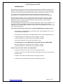
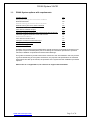
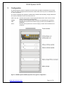
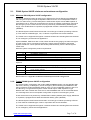
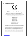
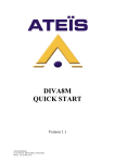
1
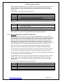
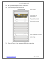
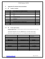
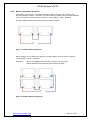
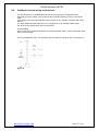
DIVA8 System VACIE D E L I V E R I N G Y o u r M E S S A G E DIVA8 SYSTEM VACIE Reference System Guide DIVA8MG2-M/S-10VRS01-V03R03 www.ateis-europe.com ATEÏS Europe BV - Sydneystraat 42 - 3047BP ROTTERDAM - NETHERLANDS Phone +31 (0)10 2088690 - Fax +31 (0)10 2088699 P.O. box 12172, 3004 GD, ROTTERDAM - Chamber of commerce: 24465391 Rotterdam www.ateis-europe.com Page 1 of 30 DIVA8 System VACIE INTRODUCTION: 4 1.1. DIVA8 SYSTEM OPTIONS WITH REQUIREMENTS 5 2. CONFIGURATION 6 2.1. DIVA8 SYSTEM VACIE MINIMUM AND MAXIMUM CONFIGURATION 2.1.1. MINIMUM DIVA8 SYSTEM VACIE CONFIGURATION 2.1.2. TYPICAL DIVA8 SYSTEM VACIE CONFIGURATION 2.1.3. MAXIMUM DIVA8 SYSTEM VACIE CONFIGURATION 7 7 7 8 3. INSTALLATION REQUIREMENTS 9 3.1. MECHANICAL AND ELECTRICAL 3.2. CABLING INTERCONNECTIONS 3.3. POWER REQUIREMENTS 9 9 10 4. DIVA8 SYSTEM VACIE PRODUCT DESCRIPTION 11 4.1.1. DIVA8G2M MASTER UNIT 4.1.2. DIVA8S SLAVE UNIT 4.2. DPAFOUR125 OR DPAFOUR125, D-‐CLASS AMPLIFIER 4.3. SPA 2.120 AND 2.240, AB-‐CLASS AMPLIFIER 4.4. PSSG2 AND PSS-‐TOUCH-‐G2 4.5. CD16 AND CD8 4.6. CABINET 4.7. MINIMAL RACK REQUIREMENTS FOR ALTERNATIVE RACKS 11 11 12 12 12 13 14 14 5. INTERFACING WITH CIE 18 6. APPENDIX A, PRODUCT DOCUMENTATION 19 6.1. A1 PRODUCT REFERENCE GUIDES 6.2. A2 WIRING EXAMPLES FIGURE 1 AND 2 6.3. A3 MINIMUM DIVA8 SYSTEM VACIE CONFIGURATION 6.4. A4 TYPICAL DIVA8 SYSTEM VACIE CONFIGURATION 6.4.1. TYPICAL DIVA8 SYSTEM VACIE RACK VIEW 6.5. FIGURE 6: TYPICAL DIVA8 SYSTEM VACIE RACK CONFIGURATION 6.5.1. TYPICAL DIVA8 SYSTEM VACIE BLOCK DIAGRAM 19 20 21 22 22 22 23 7. APPENDIX B, ELECTRICAL DOCUMENTATION 24 7.1. B1 INSTALLER CHECKLIST 7.2. B3 POWER REQUIREMENTS 7.3. POWER SONIC BATTERIES 24 24 25 www.ateis-europe.com Page 2 of 30 DIVA8 System VACIE 7.3.1. B4 BATTERY SPECIFICATIONS, POWER SONIC 7.3.2. BATTERY CASCADING INSTRUCTION 7.4. ADDITIONAL EXTERNAL WIRING REQUIREMENTS 7.5. B5 RITTAL RACK DETAILS, TYPICAL DIVA8 SYSTEM CONFIGURATION 7.6. CE VACIE STICKER LOCATION 25 26 27 28 29 8. INTERNATIONAL SALES AND SERVICE POINTS 30 Figure 1: DIVA8 System VACIE equipment rack, typical configuration ......................................6 Figure 2: DIVA8M Master unit and DIVA8S Slave unit in single amplifier configuration ..........20 Figure 3: DIVA8M Master unit and DIVA8S Slave unit in multi amplifier configuration ............20 Figure 4: Minimum DIVA8 System VACIE RACK configuration ..............................................21 Figure 5: Minimum DIVA8 System VACIE block diagram ........................................................21 Figure 6: Typical DIVA8 System VACIE RACK configuration ..................................................22 Figure 7: 24VDC/75AH arrangement........................................................................................26 Figure 8: 24VDC/150AH arrangement......................................................................................26 www.ateis-europe.com Page 3 of 30 DIVA8 System VACIE Introduction: DIVA8 System VACIE (Voice Alarm and Indicating Equipment) is designed to respond to the European standard EN54-16 to provide emergency announcements and commercial paging st systems in accordance with the standards that will become mandatory from March 31 2011. In accordance to the CEN/CENELEC Internal Regulations, the national standards organizations of the following countries are bound to implement this European Standard: Austria, Belgium, Bulgaria, Cyprus, Czech Republic, Denmark, Estonia, Finland, France, Germany, Greece, Hungary, Iceland, Ireland, Italy, Latvia, Lithuania, Luxembourg, Malta, Netherlands, Norway, Poland, Portugal, Romania, Slovakia, Slovenia, Spain, Sweden, Switzerland and the United Kingdom. The DIVA8M System includes Control and Indicator Equipment, Multi Channel Amplifiers and Emergency desk and Wall Station paging consoles. All certified components are to be combined in one central equipment cabinet. DIVA8 System is NOT designed for decentralised multi-cabinets applications. The following components are part of the integrated DIVA8M System VACIE concept: • DIVA8 System: DIVA8M Master unit, 5inx8out matrix, A/B-loudspeaker line out, incl. secured firemen microphone • DIVA8 System: DIVA8S Slave unit, additional 8out matrix, A/B- loudspeaker line out • D-Class Amplifiers 19”: DPAfour125, Power amplifier, 4x125W D-Class Amplifiers 19”: DPAfour250, Power amplifier, 4x250W • Power Sonic batteries: PS-12750 12V75AH (Max. 4 pcs) OR INSTEAD OF D-Class AMPLIFIERS, ANALOGUE AB-Class AMPLIFIERS: • AB-Class Amplifiers 19”: SPA2.120, Power amplifier, 2x120W AB-Class Amplifiers 19”: SPA2.240, Power amplifier, 2x240W Optional and positioned outside of the VACIE Rack: • Consoles: PSS-G2, Colour touch screen remote paging console • Consoles: PSS-Touch-G2, Wall mounted programmable Colour touch screen remote paging console • Consoles: CD-8, Wall mounted remote 8-zone paging console • Consoles: CD-16, Wall mounted remote 16-zone paging console www.ateis-europe.com Page 4 of 30 DIVA8 System VACIE 1.1. DIVA8 System options with requirements Audible warning voice alarm condition Delay(s) to entering the Phased evacuation Manual silencing of the voice alarm condition Manual reset of the voice alarm condition Output to alarm devices Voice alarm condition output Indication of faults related to the transmission path of t he CIE Indication of faults related to voice alarm zones Disablement condition Voice alarm manual control Interface to external control device(s) Emergency microphones Redundant amplifiers Yes No Yes No Yes No Yes Yes Yes No Yes Yes Yes Yes Installers and operators of the DIVA8 System should review the functionality and interconnect principles unique to DIVA8 System prior to reviewing the information presented in operation manuals, installation requirements and associated drawings. This guide is intended to provide users with a reference to the documentation that can provide a good understanding of the system architecture, the purpose and specifications of individual equipment that make up the VACIE, the operation of the system and the installation processes required. Please refer to 7.1 Appendix A1, for reference to support documentation. www.ateis-europe.com Page 5 of 30 DIVA8 System VACIE 2. Configuration The DIVA8 System VACIE is supplied in a RITTAL DK type 24HE 19”rackframe with an IP30 rating. The rack is equipped with access doors at both sides with a key-lock for ACCESS level 2, 3 and 4 protection. The rack is equipped with amplifiers, DPAfour250 or SPA2.240 and battery charger, BECS150 and remote controllers can be connected, such as: PSS-Touch-G2 PSSG2 CD8 CD16 Remote security wall- mounted programmable Colour touch screen remote paging console with ACCESS level 2 Remote security desktop Paging console with ACCESS level 2 protection Remote security wall-mount 8-zone Paging console with ACCESS level 2 protection. Remote security wall-mount 16-zone Paging console with ACCESS level 2 protection. Figure 1: DIVA8 System VACIE equipment rack, typical configuration www.ateis-europe.com Page 6 of 30 DIVA8 System VACIE 2.1. DIVA8 System VACIE minimum and maximum configuration 2.1.1. Minimum DIVA8 System VACIE configuration A minimum standard system will service up to 8 Emergency Zones following the BS5839 for A/B wiring and requires a single loudspeaker cable for zone A or two loudspeaker cables in case of A and B zoning. The DIVA8 System VACIE should require at least ONE amplifier of type DPAfour125 or SPA2.120 and assigned to service the speaker configuration required in the emergency zones. These devices are to be powered by certified battery-backed power supply, such as BECS150 or equivalent, equipped with at least a 75AH/24VDC battery pack (1800WH). The DIVA8 System VACIE should be housed in an IP30 type of cabinet (according to EN 542). This could be a Rittal DK type, 12U, of cabinet or equivalent with forced ventilation. The VACIE can be supported throughout a network infrastructure including Ethernet Switches for non-emergency remote service applications. Optional PSSG2, PSS-Touch-G2 or CD8, CD16 remote security paging consoles with higher or lower priority can be connected for emergency paging purpose outside of the DIVA8 System VACIE rack. These optional devices are powered directly from the DIVA8 System VACIE rack. Minimum system configuration product requirements: 1x 1x 1x 1x 2x VACIE Equipment rack, 12U with forced ventilation DIVA8MG2, Master unit DPAfour125 or SPA2.120, Power amplifier BECS 150 or equivalent EN54-4 Battery charger PowerSonic, PS-12750 12V75AH battery or equivalent 1x 1x PSSG2, Security remote desktop paging console PSS-Touch-G2, Security remote wall- mounted programmable Colour touch screen remote. CD8, Security 8-zone remote wall mount paging console CD16, Security 16-zone remote wall mount paging console Optional: 1x 1x Please refer to 7.3 Appendix A3 Minimum DIVA8 System VACIE configuration 2.1.2. Typical DIVA8 System VACIE configuration The typical system configuration will contain ONE DIVA8MG2 Master unit and ONE DIVA8S Slave unit, servicing 16 Emergency zones. Emergency Zones following the BS5839 for A/B wiring requires a single loudspeaker cable for zone A or two loudspeaker cables in case of A and B zoning. The typical DIVA System VACIE should require TWO amplifiers of type DPAfour125 / 250 or SPA2.120 / 240. One for the DIVA8MG2 and one for the DIVA8S Slave unit. All assigned to service the speaker configuration required in the emergency zones. These devices are to be powered by certified EN54-4 battery-backed power supply, BECS150 or equivalent, equipped with at least 75AH/24VDC battery pack (1800WH) The DIVA8 System VACIE should be housed in an IP30 type of cabinet (according to EN 542). This could be a Rittal DK type of 24U or equivalent with forced ventilation. The VACIE can be supported throughout a network infrastructure including Ethernet Switches for non emergency remote service applications. www.ateis-europe.com Page 7 of 30 DIVA8 System VACIE Optional PSSG2, PSS-Touch-G2 or CD8, CD16 remote security paging consoles with higher or lower priority can be connected for emergency paging purpose outside of the DIVA8 System VACIE rack. These optional devices are powered directly from the DIVA8 System VACIE rack. Typical system configuration product requirements: 1x 1x 1x 2x 1x 2x VACIE Equipment rack, 24U with forced ventialtion DIVA8MG2, Master unit DIVA8S, Slave unit DPAfour250 or SPA2.240, Power amplifier BECS 150 or equivalent EN54-4 Battery charger PowerSonic, PS-12750 12V75AH battery or equivalent 1x 1x PSSG2, Security remote desktop paging console PSS-Touch-G2, Security remote wall- mounted programmable Colour touch screen remote. CD8, Security 8-zone remote wall mount paging console CD16, Security 16-zone remote wall mount paging console Optional: 1x 1x Please refer to 7.4 Appendix A4 Typical DIVA8 System VACIE configuration 2.1.3. Maximum DIVA8 System VACIE configuration A maximum system configuration will contain ONE DIVA8MG2 Master unit and FIFTEEN DIVA8S Slave units, servicing 128 Emergency zones. Emergency Zones following the BS5839 for A/B wiring requires a single loudspeaker cable for zone A or two loudspeaker cables in case of A and B zoning. The maximum DIVA System VACIE should require a minimum of TWO amplifiers of type DPAfour250 or SPA2.240 up to a maximum of 16. ONE for every DIVA8MG2 or DIVA8S Slave unit, generating a total power distribution of 8KW over 128 zones A/B. All assigned to service the speaker configuration required in the emergency zones. These devices are to be powered by certified battery-backed power supply, BECS150, equipped with at least 150AH/24VDC battery pack per 6 amplifiers of type DPAfour250. The DIVA8 System VACIE should be housed in an IP30 type of cabinet (according to EN 542). This could be TWO Rittal DK type of 40U cabinet or equivalent with forced ventilation. The VACIE can be supported throughout a network infrastructure including Ethernet Switches for non emergency remote service applications. Optional PSSG2, PSS-Touch-G2 or CD8, CD16 remote security paging consoles with higher or lower priority can be connected for emergency paging purpose outside of the DIVA8 System VACIE rack. These optional devices are powered directly from the DIVA8 System VACIE rack. Maximum system configuration product requirements: 2x 1x 15x 17x 3x 12x www.ateis-europe.com VACIE Equipment rack, 40U with forced ventilator DIVA8MG2, Master unit DIVA8S, Slave unit DPAfour250 or SPA2.240, Power amplifier BECS 150 or equivalent EN54-4 Battery charger PowerSonic, PS-12750 12V75AH battery Page 8 of 30 DIVA8 System VACIE Optional: 1x 1x 1x 1x PSSG2, Security remote desktop paging console PSS-Touch-G2, Security remote wall- mounted programmable Colour touch screen remote. CD8, Security 8-zone remote wall mount paging console CD16, Security 16-zone remote wall mount paging console 3. Installation requirements 3.1. Mechanical and electrical In order to ensure that the standards compliance of the DIVA8 System VACIE are not compromised, the interconnections to the Fire Detection System the FACIE, power supplies, remote paging consoles, network infrastructure and other VACIE components must be installed in accordance with the provisions of applicable electricity, cabling and safety directives. This includes the DIVA8 System VACIE operation manuals for each piece of equipment and this guide. The information contained in the appendices of this document, 7.1- A1, is the most important and provides detailed specifications and requirements for component parts. The DIVA8 System VACIE must be installed and commissioned by those who have completed the appropriate training courses conducted by ATEÏS. Once the installation and commissioning process is completed, software access to the VACIE is restricted to authorised service personnel only at Access level 4. In case multiple ‘linked’ cabinets for the DIVA8 System VACIE are used, the DIVA8MG2 Master unit and DIVA8S Slave unit are designed to be connected together and to be powered by the BECS150 EN54-4 battery charger or equivalent in each rack. Power supplies and Ethernet switches which comply with all applicable standards must be provided to support the system and the units interconnected in accordance with those standards. The system installer should be aware of the local standards and specific clauses that apply. 3.2. Cabling Interconnections Ethernet and interconnecting cabling must be installed appropriately to support standards compliance of the DIVA8 System VACIE. Specifically, any cabling between devices or that goes to remote accessories like loudspeakers and paging consoles must support the DIVA8 line detection strategy. In order to comply, DIVA8 System VACIE is equipped with impedance measuring on outgoing lines. Loudspeakers For the loudspeaker lines, a twisted pair of sufficient size needs to be used in order to ensure no bigger voltage losses than 10%. A pair is used for the A group and a second pair for the B group loudspeaker lines. (A&B in case of BSI5839 compliance) Remote consoles The paging consoles are using a standard FTP-CAT5-cable. The shield is very important and needs to be connected at both ends, rack side and paging console or junctionbox side. CIE The DIVA8 System VACIE provides an interface between the CIE and the VACIE rack. The cables that provide interconnection between the VACIE rack and CIE should be installed as a cable loom. www.ateis-europe.com Page 9 of 30 DIVA8 System VACIE Fault monitoring Typical standards compliant installations may require full monitoring. (See: Options with requirements. 1.1) The DIVA8 System VACIE monitors system health and detects alarm and fault inputs. It provides an interface to external fault contacts and alarm inputs from the CIE, and also provides an alarm/fault sounder and required secured G.F. contacts. The DIVA8 System VACIE has a voltage free relay contact (G.F.-General Fault) that is opened on system fault detection and when power is completely removed. For standards compliance, this contact is fault-secured to provide a fault indication to the CIE. Please refer to Appendix Contents Page 7.1, A1, for reference to support documentation 3.3. Power requirements The DIVA8 System VACIE is using a single 240VAC supply that is connected to separate power fuses inside. From here it is distributed towards the BECS150 Battery charger(s) and DPAxx or SPAxx Power amplifier(s). The power requirements of the DIVA8 System VACIE are easily computed due to the overall efficiency of 82% of the main power consuming devices like Amplifiers. (Rated power amplifiers x 1.20) + (BECS150 x 1.2) = Min. AC-power requirements. Please refer to Appendix Contents Page 7.1, A1, for reference to support documentation www.ateis-europe.com Page 10 of 30 DIVA8 System VACIE 4. DIVA8 System VACIE product description 4.1.1. DIVA8G2M Master unit The DIVA8M Master unit houses: audio digital signal processing (DSP), a matrix, a digital message player, a fully monitored fireman microphone, amplifier monitoring with switchover to backup amplifier and loudspeaker line monitoring. It can process and route one PSSG2xx or one CD16 remote security microphone console and two 0 dB audio inputs, plus one Mic/Line input, into 2 different channels (Music + Paging). Each input is fitted with volume controls and equalizers. All audio inputs feature contact and VOX activation (ideal when using the cordless microphone, for example). Up to 45 minutes of digital messages can be downloaded and recorded as WAV files directly from a computer into DIVA8M Master unit. Two messages can be played simultaneously in different zones. One of the messages can be used as a chime for the PSS paging console. Nine monitored alarm inputs making it possible to obtain the preprogrammed routings. Each DIVA8M - Master unit has eight output zones with a+b wiring. Each zone can be routed manually or automatically to one of the system’s audio channels (Music and Paging). The number of zones can be extended up to 128 zones with DIVA8S (Slave-unit). The two Music channels can be switched ON/OFF in each zone separately. In case of Evacuation, the Music channel can be used as a second alarm channel. From the front panels, the user can manually route the fireman microphone signal and three digital messages into the selected zones, adjust the audio level and switch (ON/OFF) the music in each zone separately. In case of evacuation, the zones attenuators are automatically bypassed. One output contact per zone (eight per unit) can be activated each time the zone is occupied with a source having a higher priority than the music (Alarm or microphone paging…) All DIVA components and peripherals are constantly monitored (without music interruption). All incidents are recorded into a data file which can be consulted on the DIVA8M master units display or on a PC. Also any detected fault and alarm status are signalled by general fault and alarm output contacts. A local loudspeaker enables selective listening to all the sources and the system’s output signals. The setup of a DIVA8 System is realised through a PC computer at ACCESS LEVEL 3 and 4 using the DIVA8 System configuration software (Windows compatible). Access can be password-protected. The routing and the level of the music sources can be controlled directly from the PSSG2 paging console. For more specific product information please see the following document: • DIVA8MG2-‐M/S-‐10UMS01-‐V01R01 DIVA8M Users manual 4.1.2. DIVA8S Slave unit DIVA8S is a Slave unit for the DIVA8M master unit. It increases the number of paging zones by 8 zones for each Slave unit added in the system. The maximum number of Slave units are 15, which means a complete system (master plus slaves) of up to 128 zones. The DIVA8S also extends the amount of input and output contacts. It includes 9 alarm inputs triggered either by dry contact or voltage (software setting), 8 logic input contacts, 2 external fault input contacts and 8 output contacts. The DIVA8S offers the same power capacity as the DIVA8 master unit being 1000 W of audio power (100 V) on each amplifier channel (voice and paging). For maximum flexibility, the DIVA8 master unit amplifiers can share their power with all the DIVA8 Slave units for economical power distribution, or additional amplifiers can be added to the DIVA8S Slave units when more output power is needed. The 100 V amplifier signal is simply linked to slaves to create a 100 V signal bus. (Appendix 0 A2: Figure 1 and 2 for wiring examples.) All the zones and amplifier channels in the DIVA8 System can be constantly monitored (software setting). www.ateis-europe.com Page 11 of 30 DIVA8 System VACIE For more specific product information please see the following document: • DIVA8MG2-‐M/S-‐10UMS01-‐V01R01 DIVA8M Users manual 4.2. DPAfour125 or DPAfour125, D-Class amplifier The DPAfour125 / 250 is a 2U high 19” rack mountable, 4-channel class-D power amplifier, transformer isolated for 100 V, 70 V, 50 V and low-impedance distributed loudspeaker systems. Each amplifier can deliver up to 2x500 Watt when used in bridged mode or as 4 individual channels of 125 or 250 Watt. This amplifier has a dual voltage mains 110/230 VAC and a 24 VDC battery back-up input which allows it to be used in combination with a BECS150 battery backup system for maximum availability and durability in the VACIE system. There are 2 types of power amplifiers available in the DPA four range of products. DPAfour125, 4x125Watt or 2x250Watt in bridge mode. DPAfour250, 4x250Watt or 2x500Watt in bridge mode. For more specific product information please see the following document: • 4.3. DPA-‐10UMS01-‐V01R01 Users manual SPA 2.120 and 2.240, AB-Class amplifier The SPA 2.120 / 240 is a 2U high 19” rack mountable, 2-channel class-AB power amplifier, transformer isolated for 100 V, 70 V, 50 V distributed loudspeaker systems. Each amplifier can deliver up to 2x240 Watt. This amplifier has a dual voltage mains 110/230 VAC and a 24 VDC battery back-up input which allows it to be used in combination with a BECS150 battery backup system for maximum availability and durability in the VACIE system. There are 2 types of power amplifiers available in the SPA range of products. SPA 2.120, 2x120Watt. SPA 2.240, 2x240Watt. For more specific product information please see the following document: • 4.4. SPA-‐10UMS01-‐V01R02 Users manual PSSG2 and PSS-Touch-G2 The PSS -G2 paging console with Access level 2 protection is a remote and secured paging console for call-paging, pre-recorded messages broadcasting and DSP matrix parameter control. The PSS-G2 units connect using a secured audio and data link between paging console and DIVA8 System devices. Its back-lit touch screen is designed for simple and userfriendly operating. The 3-hardware-keys can be freely assigned within the DIVA8 System control software. Various operating levels with password protection make the PSS-G2 a versatile device that fits well in a commercial shoppingcenter as for an industrial high security environment. All paging parameters needed for site operating can be programmed: zones assigned to the different buttons, name of zones, group of zones, messages triggering, levels adjustments and pre-call chime but also for fader control, button control or event control. The PSSG2 allows for a total of 168 keys over 12 pages allow zone or group of zones selections. Each key contains a green colour changing field indicating that the zone is occupied by a different. The PSS-Touch-G2 has the same functionality as the PSSG2 but is equipped with fist firemen’s microphone in a metal surfacemount wall-box. For more specific product information please see the following document: • PSSG2-‐10UMS01-‐V01R01 Users manual www.ateis-europe.com Page 12 of 30 DIVA8 System VACIE 4.5. CD16 and CD8 The CD16 Wall-mount heavy duty remote paging console with Access level 2 protection is a remote and secured paging console for call-paging, is compatible with DIVA8 System and communicates over a dedicated RS485 carrying power, audio and DATA. The unit comprises of 16 zones / 16 buttons with fist firemen’s microphone in a metal surface mount wall-box. It provides robust IP-30 protection. Each CD16 contains a PSM Master PCB with extension keypad and uses the same architecture as for the PSM series of microphone consoles. Each DIVA8 System can handle up to 32x CD16 units with a maximum of 10 pieces on one line in Master/Slave configuration. (Note that only the Master unit is considered as secured unit under the EN54-16, Slaves are not. DIVA8 System can only handle one secured CD16 or one secured PSSG2 at one time). The buttons can represent a single zone or a group of zones. All buttons can be programmed with drag & drop features from the DIVA8 System GUI and the PTT button can be programmed for Push-To-Talk or for latching functionality. The unit offers “Hold” and “Busy” LED signal indication in addition to the zone LED’s. These zone LED’s allow the easy identification of selection / Busy signals for the user. In addition, to comply with EN 54-16, separate POWER, FAULT and EVAC indicators are provided. The RS485 communication protocol offers daisy chaining of up to 300 m on a simple STP-CAT5 cable, and yet makes outlets easy to connect via a standard RJ45 connector. For more specific product information please see the following document: • CD16-‐10UMS01-‐V01R01 Users manual www.ateis-europe.com Page 13 of 30 DIVA8 System VACIE 4.6. Cabinet Typically the DIVA8 System VACIE is housed within one cabinet or two linked system cabinets of max. 40U for a maximum configuration. (See 2.1 for typical, minimum and maximum configuration description). A cabinet containing for a typical configuration contains all required components: - DIVA8MG2 Master unit - DIVA8S Slave unit - DPAfour 125 / 250 power amplifiers - SPA 2.120 / 240 power amplifiers - BECS150 EN54-4 battery charger and backup device or equivalent - Power Sonic batteries, 2 pieces for 24VDC75AH or 4 pieces for 24VDC150AH capacity or equivalent. - Forced ventilator mounted in the top of the cabinet If multiple DIVA8S Slave units and DPAxx or SPAxx amplifiers are required to drive a large number of loudspeakers servicing a large multi-zoned area then an additional cabinet may be added as appropriate. In order to ensure that the DIVA8MG2 System VACIE is able to be installed in a wide variety of physical locations all rack components are manufactured in IP30 rated ‘rack mount’ enclosures. To ensure correct operation, the installer needs to ascertain that access level requirements are met. To maintain standards compliance, installers must follow the Ateis installer guidelines. In some circumstances cabinet construction must limit access to rear terminals and wiring of equipment to achieve specified access levels. Please refer to 8.5 Appendix B5 Rittal Rack details for a typical DIVA8 System configuration 4.7. Minimal rack requirements for alternative racks The system cabinet must meet the following minimum requirements where an alternative cabinet is used: • Comply with Class 3k5 of EN 60721-3-3:1995 as amended by EN 60721-3-3:1995/A2:1997. • Complies with EN 60297-3-100 and be constructed with a minimum of 16-gauge steel, with a fully welded rack frame with fixed front to back equipment chassis carriers. • Have a transparent lockable front door with a maximum frame size around the transparent window such that it indications are viewable at the limits specified in EN54-16: 2008. • Have a minimum IP rating of IP 30 in accordance with EN 60529: 2000, with the front hinged door in both the open and closed position • Removable / hinged panel(s), that are provided to gain access to part of the equipment, other than that detailed above, must use of alternative key or different lockable mechanism to that used for the front door. www.ateis-europe.com Page 14 of 30 DIVA8 System VACIE 5. EC Declaration of conformity 0359-‐CPD-‐0140 EC Declaration of Conformity ATEÏS Technologies Inc, 8F, No. 256, Sec. 2, Chung-‐De Rd., Taichung 406, Taiwan, R.O.C. as manufacturer having sole responsibility, hereby declares that the following product versions comply with the applicable provisions of the DIRECTIVES. In case of alterations to the product, not agreed upon and not directed by ATEÏS Technologies Inc, this declaration is no longer valid. Product: DIVA8 SYSTEM VACIE comprising Models; DIVA8MG2, Master Controller DIVA8SG2, Slave Controller PSS-‐G2, Console device CD8-‐G2, Console device CD16-‐G2, Console device DPAfour125, Power amplifier DPAfour250, Power amplifier SPA-‐2120, Power amplifier SPA-‐2240, Power amplifier Powersonic, PS-‐12750 12V75AH battery, Mounted in the bottom of the enclosure DK7820.XXX Rittal System cabinet* XXX – denotes cabinet size The system cabinet must meet the following minimum requirements where an alternative cabinet is used: • Comply with Class 3k5 of EN 60721-‐3-‐3:1995 as amended by EN 60721-‐3-‐3:1995/A2:1997. • Complies with EN 60297-‐3-‐100 and be constructed with a minimum of 16-‐gauge steel, with a fully welded rack frame with fixed front to back equipment chassis carriers. • Have a transparent lockable front door with a maximum frame size around the transparent window such that it indications are viewable at the limits specified in EN54-‐16: 2008. • Have a minimum IP rating of IP 30 in accordance with EN 60529: 2000, with the front hinged door in both the open and closed position • Removable / hinged panel(s), that are provided to gain access to part of the equipment, other than that detailed above, must use of alternative key or different lockable mechanism to that used for the front door. www.ateis-europe.com Page 15 of 30 DIVA8 System VACIE Conditions of use: Suitable for indoor applications To be used in conjunction with a compliant EN54-‐4 power supply unit Applicable Directive: In compliance with the Directive 89/106/EEC of the council of European Communities of 21 December 1988 on the approximation of laws, regulations and administrative provisions of the Member States relating to the construction products (Construction Products Directive – CPD), amended by the Directive 93/68/EEC of the Council of European Communities of 22 July 1993. Evaluation standard: EN54-‐16:2008 Fire detection and fire alarm systems – Part 16: Voice Alarm Control and Indicating Equipment Provided Options: -‐ Audible warning -‐ Phased evacuation -‐ Manual rest of the voice alarm condition -‐ Voice alarm condition output -‐ Indication of faults related to the transmission path of the CIE -‐ Indication of faults related to the voice alarm zones -‐ Interface to external control device(s) -‐ Emergency microphones -‐ Redundant amplifiers Ancillary Functions: Background music/audio and zone paging (2-‐simultaneous channels) Notified body (Test and Certification): Intertek Testing & Certification Limited Intertek House, Cleeve Road, Leatherhead, Surrey, KT22 7SB, UNITED KINGDOM Notified Body number: 035 First placed on the market by: ATEÏS Europe BV Sydneystraat 42 3047BP ROTTERDAM NETHERLANDS Telephone: +31 10 2088690 Fax: +31 10 2088699 Email: info@ateis-‐europe.com Issued: March 2012 Authorized Representative: J.H.E. Haak (Managing Director) Authorized signature: D E L I V E R I N G Y o u r M E S S A G E www.ateis-europe.com Page 16 of 30 DIVA8 System VACIE 5.1. First power-up and Maintenance This section describes the standard electrical and mechanical safety test that are to be performed before powering up the DIVA8 System VACIE and on regular intervals with a maximum of 12 months. • • • • • • • A: VACIE Rack & Electrical Safety Tests Inspect for the EN54-2 for the outside of the rack if it complies to the IP30 standards Inspect for EN54-16 compliance notification at the front of the rack Inspect for EN54-4 compliance on the charger Inspect on EN54-24 compliance for the loudspeakers Inspect in the front and back door are closed at ACCESS level 2, front door and 3, back door Inspect for GOOD visibility of the VACIE indicators (EN54-2) Inspect and measure the VACIE rack assembly earth (ground) bonding (EN54-1) • B: Amplifier Assembly Inspect the general physical condition of the assembly, including the terminations for loose connections • Inspect and check the performance of each power amplifier • Inspect and check the condition of the back-up batteries, including recording the block voltages off charger and conduct a discharge test to determine the maximum capacity. • Inspect and check the operation of the charging equipment, including the fault sensing • • Inspect the stored message generator modules and check the output for the quality of reproduction, together with correct operation within the system Inspect and check the input pre-amplification / mixing equipment. Record and compare the settings with the latest recorded data. Note any deviations for investigation. Any changes made at this time to be noted • Inspect and check the operation of the fire panel interface, in conjunction with Clients engineer. • • Inspect and check the function of any equalization. Record and compare the settings of the controls with the latest recorded data. Any deviations to be noted and investigated With the evacuation broadcast in operation utilizing a dummy load when the main speakers cannot be used, check the output level of each power amplifier. Record and compare the results with the latest data • Check the system automatic fault monitoring and test by introducing faults C: Loudspeakers • Measure the total loudspeaker load for each circuit, record and compare with the previous measurements. Investigate any unexpected changes • Carry out subjective listening and audibility tests in all areas where access is not prohibited. Record SPL levels D: Microphone Control Units • Inspect and check the condition as well as the correct operation of the switches/touch fields • • Inspect the physical conditions of the microphone Broadcast a test message, or if prohibited, use a monitor loudspeaker to access the results subjectively E: Spare Modules • Inspect and check any spare modules contained in the amplifier assembly and/or held elsewhere F: System Condition • Cosmetic cleaning of the control and amplification equipment G: Site Changes • Inspect any areas which have changed since a previous (as identified by the Client) to determine the suitability of the loudspeaker coverage in those areas H: Log Book www.ateis-europe.com Page 17 of 30 DIVA8 System VACIE • Enter summary details of the visit in the logbook on completion I: Work Sheets • Obtain a signature by a responsible person to verify that the system is being left in a satisfactory condition on completion of the work J: Reporting • 6. Following the visit a report with any recommendations will be provided Interfacing with CIE A. VACIE Inputs from CIE • The typical DIVA8 System VACIE provides for up to 16 secured voice alarm inputs, ONE voice alarm silence and ONE voice alarm reset secured input. These inputs and associated circuitry have been designed so that a fault on these inputs will not cause a change of operation. B. Voice Alarm Silence • The voice alarm silence provides the ability to mute all active emergency messages. To activate a voice alarm silence a contact is received from the CIE. Upon activation the active emergency messages will immediately mute and remain in this state until either: 1. A second alarm input is detected and the alarm silence is removed 2. The voice alarm reset is activated C. Voice Alarm Reset • The voice alarm reset provides a reset function to remove all active voice alarms. This input is activated by contact coming from the CIE. D. VACIE Outputs to CIE • Voice Alarm Active This constant active output provides indication of when an emergency message is playing in response to a voice alarm input. • General Fault This contact opens when the power to the VACIE is completely removed, a fault is generated by the BECS150 – Battery charger or the DPAxx or SPAxx amplifier(s) or any detection on loudspeaker lines and remote paging consoles PSSxx / CDxx or any kind of processing fault in the DIVA8MG2/DIVA8S www.ateis-europe.com Page 18 of 30 DIVA8 System VACIE 7. Appendix A, product documentation 7.1. A1 Product reference guides 19 PSSG2-‐10SGS01-‐V01R01 DIVA8 System VACIE reference guide DIVA8 System VACIE rack drawing package DIVA8 System VACIE short guide DIVA8 Users Manual DIVA8 Technical datasheet; Processor, memory & exception guide DIVA8 Service Manual DIVA8 Software Guide BECS150 Users Manual BECS150 Technical datasheet; Processor, memory & exception guide BECS150 Software Guide DPA Users Manual DPA Technical datasheet; Processor, memory & exception guide DPA Software Guide SPA Users Manual SPA Technical datasheet; Processor, memory & exception guide SPA Software Guide PSSG2 Users Manual PSSG2 Technical datasheet; Processor, memory & exception guide PSSG2 Software Guide 17 CD16-‐10UMS01-‐V01R01 CD16 Users Manual 18 CD16-‐10TSS01-‐V01R01 19 CD16-‐10SGS01-‐V01R01 CD16 Technical datasheet; Processor, memory & exception guide CD16 Software Guide 23 24 25 1 2 3 4 5 DIVA8MG2-‐M/S-‐10VRS01-‐V03R03 DIVA8MG2-‐M/S-‐10VRS02-‐V01R01 DIVA8MG2-‐M/S-‐10VRS03-‐V01R01 DIVA8MG2-‐M/S-‐10UMS01-‐V01R01 DIVA8MG2-‐M/S-‐10TSS01-‐V01R01 6 DIVA8MG2-‐M/S-‐10SMS01-‐V01R01 7 DIVA8MG2-‐M/S-‐10SGS01-‐V01R01 8 BECS150-‐10UMS01-‐V01R01 9 BECS150-‐10TSS01-‐V01R01 10 BECS150-‐10SGS01-‐V01R01 11 DPA-‐10UMS01-‐V01R01 12 DPA-‐10TSS01-‐V01R01 13 DPA-‐10SGS01-‐V01R01 14 SPA-‐10UMS01-‐V01R01 15 SPA-‐10TSS01-‐V01R01 16 SPA-‐10SGS01-‐V01R01 17 PSSG2-‐10UMS01-‐V01R01 18 PSSG2-‐10TSS01-‐V01R01 www.ateis-europe.com Page 19 of 30 DIVA8 System VACIE 7.2. A2 Wiring examples Figure 1 and 2 Figure 2: DIVA8M Master unit and DIVA8S Slave unit in single amplifier configuration. DPAxx or SPAxx Figure 3: DIVA8M Master unit and DIVA8S Slave unit in multi amplifier configuration. DPAxx or SPAxx www.ateis-europe.com Page 20 of 30 DIVA8 System VACIE 7.3. A3 Minimum DIVA8 System VACIE configuration Figure 4: Minimum DIVA8 System VACIE RACK configuration Figure 5: Minimum DIVA8 System VACIE block diagram www.ateis-europe.com Page 21 of 30 DIVA8 System VACIE 7.4. A4 Typical DIVA8 System VACIE configuration 7.4.1. Typical DIVA8 System VACIE rack view 7.5. Figure 6: Typical DIVA8 System VACIE RACK configuration www.ateis-europe.com Page 22 of 30 DIVA8 System VACIE 7.5.1. Typical DIVA8 System VACIE block diagram www.ateis-europe.com Page 23 of 30 DIVA8 System VACIE 8. Appendix B, electrical documentation 8.1. B1 Installer checklist Item 1 2 3 Requirements Are you aware of the applicable standards? Did you read the Ateis applicable reference guides? Does the VACIE rack provide ACCESS level 2 protection at the front? Does the VACIE rack provide ACCESS level 3 protection at the rear? Does the VACIE rack carry a clear VACIE EN54-16 compliance marking at the front? Are the VACIE mandatory indicators clearly visible according to the EN54-2? Did you checked the MAINS and DC provisions? Is the MAINS of sufficient capacity? Check power calculation Are the BATTERIES of sufficient capacity? Loudspeaker cabling is of sufficient size? Cabling to remote devices is of sufficient quality? 4 5 6 7 8 9 10 11 12 8.2. B3 Y/N Power requirements The power requirements of the DIVA8 System VACIE are easily computed due to the overall efficiency of 82% on AC. (Rated power amplifiers x # x 1.20) + (BECS150 x # x 1.2) = Min. AC-power (W). • Please refer to Appendix Contents at 7.1, A1, for reference to support documentation Product Power requirements DIVA8MG2 DIVA8S DPA four 125 DPA four 125 DPA four 125 DPA four 250 DPA four 250 DPA four 250 SPA 2.120 SPA 2.120 SPA 2.120 SPA 2.240 SPA 2.240 SPA 2.240 PSSG2 & PSS-Touch-G2 CD16 & CD8 24VDC ± 20% 24VDC ± 20% 240VAC/24VDC ± 15% 240VAC/24VDC ± 15% 240VAC/24VDC ± 15% 240VAC/24VDC ± 15% 240VAC/24VDC ± 15% 240VAC/24VDC ± 15% 240VAC/24VDC ± 15% 240VAC/24VDC ± 15% 240VAC/24VDC ± 15% 240VAC/24VDC ± 15% 240VAC/24VDC ± 15% 240VAC/24VDC ± 15% 24VDC ± 20% 24VDC ± 20% www.ateis-europe.com Power consumption 17W 9W 526W MAX 40W @ 20kHz 2.5W Idle 1052W MAX 40W @ 20kHz 2.5W Idle 644W MAX 299W @ 20kHz 55W Idle 1311W MAX 575W @ 20kHz 129W Idle 10W Nominal 6W Nominal Page 24 of 30 DIVA8 System VACIE 8.3. Power Sonic Batteries 8.3.1. B4 Battery specifications, Power Sonic Physical Specifications PS-12750 12V75AH Nominal Voltage Nominal Capacity 12V 75.0AH Dimensions 259± 2mm 168± 2mm 208± 2mm 212± 2mm Length Width Container Height Total Height (with terminal) Weight Approx. 21.0kg Standard Terminal T6 Note: Battery needs to be supported by a 30x30mm profile. (see drawing) www.ateis-europe.com Page 25 of 30 DIVA8 System VACIE 8.3.2. Battery cascading instruction Total battery voltage to be connected to the EN54-4 battery charger and monitoring unit should be 24VDC ( 19VDC – 26.5VDC). To achieve this, two Power sonic PG-12V75 batteries can be connected in series as shown in figure 7. (Total capacity: 75AH - 1800WH) Important: Red and blue wires should be equal in size and length. Figure 7: 24VDC/75AH arrangement Higher capacity can be obtained by applying a series-parallel circuit as shown in figure 8. (Total capacity: 150AH - 3600WH) Important: BLACK and GREEN wires should be equal in size and length. RED and BLUE wires should be equal in size and length. Figure 8: 24VDC/150AH arrangement www.ateis-europe.com Page 26 of 30 DIVA8 System VACIE 8.4. Additional external wiring requirements For all external wiring, shielded cables should be used except for loudspeaker wires. Especially for longer cables, care should be taken that this shielding is firmly connected to earth. Logic inputs,connected externally with wires longer than 3m, should be provided with ferrite clamps. (f.i. Wurth STER-TEC & STAR-FIX LFS or equivalent to cover the 300k-1GHz range) For all other long cables this is also recommended. Internal cabling : High current wires should be separated from audio and data cabling. Use of a separate cable duct is recommended. For long loudspeaker wires, it is advised to add an external surge protection circuit.(figure x) Figure X www.ateis-europe.com Page 27 of 30 DIVA8 System VACIE 8.5. B5 Rittal Rack details, typical DIVA8 System configuration 8.6. Forced air ventilator to be integrated in the top-panel of the cabinet. Rittal RACK, IP30 Frondoor glazed, backdoor blinded steel Rittal System chassis 1x DK 7820.300 Rittal Side panels 2x TS 8170.235 Rittal 19-inch supports 4x DK 7827.120 Rittal forced air ventilator, 230VAC 1x SK 3149.420 www.ateis-europe.com 4x TS 8612.060 Page 28 of 30 DIVA8 System VACIE CE VACIE sticker location The sticker shown below (figure 1) will be affixed on the right top corner of the glass front of the Diva Vacie system rack, as shown in figure 2. Figure 1 - CE marking & CPD nr Figure 2 – Sticker location on the system rack www.ateis-europe.com Page 29 of 30 DIVA8 System VACIE 9. International sales and service points www.ateis-europe.com Page 30 of 30