1
EURODESK
SL3242FX-PRO/SL2442FX-PRO
User Manual
A50-24413-00002
EURODESK SL3242FX-PRO/SL2442FX-PRO
Important Safety Instructions
1) Read these instructions.
2) Keep these instructions.
3) Heed all warnings.
4) Follow all instructions.
5) Do not use this apparatus near water.
6) Clean only with dry cloth.
**
This symbol, wherever it appears, alerts you to the
presence of uninsulated dangerous voltage inside the
enclosure - voltage that may be sufficient to constitute
a risk of shock.
!!
This symbol, wherever it appears, alerts you to important operating and maintenance instructions in the
accompanying literature. Please read the manual.
Caution
++ To reduce the risk of electric shock, do not remove the
top cover (or the rear section). No user serviceable parts
inside. Refer servicing to qualified personnel.
Caution
++ To reduce the risk of fire or electric shock, do not expose
this appliance to rain and moisture. The apparatus shall
not be exposed to dripping or splashing liquids and no
objects filled with liquids, such as vases, shall be placed
on the apparatus.
Caution
++ These service instructions are for use by qualified service personnel only. To reduce the risk of electric shock
do not perform any servicing other than that contained in
the operation instructions. Repairs have to be performed
by qualified service personnel.
7) Do not block any ventilation openings. Install in accordance with the manufacturer’s instructions.
8) Do not install near any heat sources such as radiators,
heat registers, stoves, or other apparatus (including
amplifiers) that produce heat.
9) Do not defeat the safety purpose of the polarized or
grounding-type plug. A polarized plug has two blades
with one wider than the other. A grounding-type plug
has two blades and a third grounding prong. The wide
blade or the third prong are provided for your safety. If
the provided plug does not fit into your outlet, consult an
electrician for replacement of the obsolete outlet.
10) Place the power cord so that it is protected from being
walked on and sharp edges. Be sure that the power cord is
protected particularly at plugs, convenience receptacles
and the point where it exits from the apparatus.
11) The apparatus shall be connected to a MAINS socket
outlet with a protective earthing connection.
12) Where the MAINS plug or an appliance coupler is used
as the disconnect device, the disconnect device shall
remain readily operable.
13) Use only attachments/accessories specified by the
manufacturer.
14) Use only with the cart, stand, tripod, bracket, or table
specified by the manufacturer, or sold with the apparatus.
When a cart is used, use caution when moving the cart/
apparatus combination to avoid injury from tip-over.
15) Unplug this apparatus during lightning storms or when
unused for long periods of time.
16) Refer all servicing to qualified service personnel. Servicing is required when the apparatus has been damaged in
any way, such as power supply cord or plug is damaged,
liquid has been spilled or objects have fallen into the apparatus, the apparatus has been exposed to rain or moisture,
does not operate normally, or has been dropped.
2
EURODESK SL3242FX-PRO/SL2442FX-PRO
Foreword
Table of contents
1. Introduction.......................................................................... 4
Dear Customer,
Welcome to the team of
EURODESK users and
thank you very much for
expressing your confidence in BEHRINGER
products by purchasing
this mixing console.
It is one of my most pleasant tasks to write this letter to you, because it is
the culmination of many
months of hard work delivered by our engineering team to reach a very
ambitious goal: to present
you two outstanding mixing consoles that give you
maximum flexibility and
performance with a unique
sound character and broad
range of striking functions. The task to design the new SL series
certainly meant a great deal of responsibility, which we assumed by
focusing on you, the discerning user and musician. It also meant a
lot of work and night shifts to accomplish this goal. But it was fun,
too. Developing a product usually brings a lot of people together,
and what a great feeling it is when everybody who participated in
such a project can be proud of what we’ve achieved.
It is our philosophy to share our joy with you, because you are
the most important member of the BEHRINGER team. With your
highly competent suggestions for new products you’ve greatly
contributed to shaping our company and making it successful.
In return, we guarantee you uncompromising quality as well as
excellent technical and audio properties at an extremely favorable
price. All of this will enable you to fully unfold your creativity without
being hampered by budget constraints.
We are often asked how we can make it to produce such highgrade devices at such unbelievably low prices. The answer is
quite simple: it’s you, our customers! Many satisfied customers
means large sales volumes enabling us to get better conditions
of purchase for components, etc. Isn’t it only fair to pass this
benefit back to you? Because we know that your success is our
success, too!
I would like to thank all people whose help on “Project SL” has
made it all possible. Everybody has made very personal contributions, starting from the designers of the unit to the many staff
members in our company and finally to you, the user of BEHRINGER products.
My friends, it’s been worth the trouble!
Thank you very much,
1.1 Before you get started................................................... 4
1.1.1 Shipment.............................................................. 4
1.1.2 Initial operation.................................................... 4
1.1.3 Online Registration.............................................. 4
1.2 The manual................................................................... 4
2. Control elements and connections.................................... 5
2.1 Mono input channels..................................................... 5
2.1.1 Microphone and line inputs.................................. 5
2.1.2 Equalizer.............................................................. 5
2.1.3 Aux/FX send buses.............................................. 5
2.1.4 Mono channel fader
and further control elements................................ 6
2.2 Stereo channels............................................................ 6
2.2.1 Channel inputs..................................................... 6
2.2.2 Stereo channel equalizer..................................... 6
2.2.3 Stereo channel aux/FX send buses..................... 6
2.2.4 Stereo channel fader
and othercontrol elements................................... 7
2.3 Stereo channels 21 - 24 (SL2442FX-PRO)
or 29 - 32 (SL3242FX-PRO)......................................... 7
2.4 Subgroups 1 - 4............................................................. 7
2.5 Mono out section for subwoofer applications................ 8
2.6 Main out section............................................................ 8
2.6.1 Talkback............................................................... 9
2.6.2 Phones & control room........................................ 9
2.7 CD/tape......................................................................... 9
2.8 Master aux send 1 and 2............................................... 9
2.9 Graphic 9-band stereo equalizer................................. 10
2.10 Effects section........................................................... 10
2.11 Rear panel..................................................................11
3. Digital effects processor.................................................. 11
4. Wiring examples................................................................ 12
4.1 Studio set-up............................................................... 12
4.2 Live set-up................................................................... 13
5. Audio connectors.............................................................. 14
6. Presets............................................................................... 15
7. Specifications.................................................................... 16
Uli Behringer
8. Warranty ............................................................................ 17
3
EURODESK SL3242FX-PRO/SL2442FX-PRO
1. Introduction
++ We recommend that you use a flight case to give the unit
optimum protection during use or transport.
Congratulations! With the EURODESK you have acquired a stateof-the-art mixing console that sets new standards. Right from the
very start it has been our goal to design a revolutionary unit that
can be used for a great variety of applications. And indeed, this
overwhelming mixing console gives you plenty of functionality and
a broad range of connection and expansion options.
BEHRINGER is a company with its roots in professional recording
studio technology. For many years now we have been successful
in developing products for studio and live use. These include microphones and studio gear of all kinds (compressors, enhancers,
noise gates, tube processors, headphone amplifiers, digital effects,
DI boxes, etc.), monitor and P.A. speakers as well as professional
live and recording mixers. Our entire technical know-how has gone
into your EURODESK mixing console.
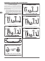
FBQ Feedback Detection System
++ Always use the original box to prevent damage during
storage or transport.
++ Make sure that children cannot play unsupervised with
the unit or its packaging.
++ Please ensure proper disposal of all packing
materials.
1.1.2 Initial operation
Ensure adequate air supply and to avoid overheating do not place
the unit near radiators etc.
++ Blown fuses must be replaced by fuses of the correct
rating! Please refer to the "SPECIFICATIONS" section
for the applicable rating.
One of the most outstanding features of this console
is the FBQ Feedback Detection System, which is
part of the graphic equalizer. This ingenious circuit
makes it possible to detect and subsequently
eliminate feedback frequencies very quickly. FBQ
increases the brightness of the EQ fader LEDs for the frequency
bands where feedback is occurring. What used to be a tedious
search for feedback frequencies is now mere child’s play.
For connection to the mains use the enclosed power cord with cold
connector which complies with the relevant safety regulations.
IMP “Invisible” Mic Preamp
==130 dB of dynamic range and hence an
unbelievable amount of headroom,
++ We would like to point out that high volume levels
may damage your hearing and/or your headphones/
loudspeakers. To avoid switch-on/off thumps from the
console and any downstream devices, always make
sure that your power amp(s) or active speakers are the
last components that are switched on and the first to
be switched off. Always make sure that the appropriate
volume is set.
== a bandwidth from below 10 Hz to above 200 kHz for the crystalclear reproduction of even the slightest details,
Important notes concerning installation
The microphone channels are equipped with
BEHRINGER’s brand-new high-end IMP Invisible Mic Preamps, which offer you:
== extremely noise and distortion-free circuitry for absolutely
natural sound and neutral signal reproduction,
== perfect adaptation to any microphone on the market (upto 60
dB gain and +48 V phantom power), and
== the possibility of pushing the dynamic range of your 24-bit/192kHz HD recorder to the max and thus achieving ultimate
audio quality.
What is more, the EURODESK comes with two effects processors using 24-bit A/D and D/A converters and the effects algorithms of our renowned 19"
multi-effects device VIRTUALIZER PRO DSP2024P.
Each processor offers 99 presets with first-class room
simulations, delay and modulation effects as well as compressor,
tube distortion and numerous other effects available—all with
excellent audio quality!
The mixer is equipped with a state-of-the-art integrated switch-mode power supply. Unlike conventional
designs, this supply automatically adapts to supply
voltages between 100 and 240 V. With its considerably higher efficiency, it is also more economical in
terms of power consumption than standard power supply units.
++ Please make sure that all devices are properly grounded.
For your own safety, never remove or disable the ground
conductors from the devices or on the power cords. The
unit must always be connected to the mains outlet with
a protective grounding connection.
++ The sound quality may diminish within the range of powerful broadcasting stations and high-frequency sources.
Increase the distance between the transmitter and the
device and use shielded cables for all connections.
1.1.3 Online Registration
Please register your new BEHRINGER equipment right after your
purchase by visiting http://www.behringer.com and read the terms
and conditions of our warranty carefully.
Should your BEHRINGER product malfunction, it is our intention
to have it repaired as quickly as possible. To arrange for warranty
service, please contact the BEHRINGER retailer from whom the
equipment was purchased. Should your BEHRINGER dealer
not be located in your vicinity, you may directly contact one of
our subsidiaries. Corresponding contact information is included
in the original equipment packaging (Global Contact Information/
European Contact Information). Should your country not be listed,
please contact the distributor nearest you. A list of distributors
can be found in the support area of our website (http://www.
behringer.com).
Registering your purchase and equipment with us helps us process
your repair claims more quickly and efficiently.
Thank you for your cooperation!
1.1 Before you get started
1.2 The manual
1.1.1 Shipment
Your product was carefully packed at the factory to ensure safe
transport. Nevertheless, if the box is damaged inspect the unit
immediately for signs of damage.
++ If the unit is damaged please do NOT return it to us,
but notify your dealer and the shipping company immediately; otherwise, claims for damage or replacement
may not be granted.
4
This manual is designed to give you an overview of all control elements and at the same time inform you in detail about how to use
them. To provide you with a clear structure, we have grouped the
control elements according to their function. They can easily be
found on the enclosed numbered illustrations. If you need more
detailed information on specific topics, please visit our web site
at www.behringer.com. The product-related information pages
and the ULTRANET-based glossary explain the relevant audio
engineering terminology in full detail.
Introduction
EURODESK SL3242FX-PRO/SL2442FX-PRO
2. Control elements and connections
This chapter describes the various control elements of your mixing
console. All controls and connections are explained in full detail.
2.1 Mono input channels
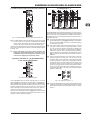
2.1.1 Microphone and line inputs
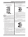
signal and the LEVEL SET LED, which will illuminate when
the optimum operating level has been set.
{5} Mono channels are equipped with a high-slope LOW CUT
filter eliminating unwanted low-frequency signals, such as
floor rumble (18 dB/oct., -3 dB at 80 Hz).
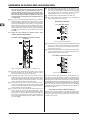
2.1.2 Equalizer
All mono input channels are equipped with a 3-band equalizer.
The maximum boost/cut of the individual bands is 15 dB, in mid
position the EQ is set to neutral.
Fig. 2.2: Equalizer section of input channels
Fig. 2.1: Connectors and controls of the mic/line inputs
{1}
Each mono input channel is
equipped with a balanced microphone input
on an XLR connector, which provides +48 V
phantom power for condenser microphones at
the touch of a button (see rear panel).
++ Be sure to switch off your audio system before you
activate the phantom power supply to prevent audible
switch-on thumps from reaching your monitor speakers. Please also note the information given in chapter
2.11 “Rear panel”.
{2} Each mono input also has a balanced line input on 1/4" TRS
connectors. Of course, these inputs can also be used with
unbalanced plugs (1/4" TS connector).
{3} The INSERT I/O connector is used to process a signal with
dynamic processors or equalizers. This insert point isprefader, pre-EQ and pre-aux send.
Unlike reverb and other effects, which are usually added to
the dry signal, dynamic processors process the entire signal.
So, aux send buses are not the best solution here. Instead,
dynamic processors and equalizers are inserted into the
signal path. Once processed, the signal then re-enters the
mixing console at the same point where it left. Signal interruption only occurs if a plug is inserted into the corresponding
jack (1/4" stereo plug: tip = signal output, ring = input). All
mono input channels are equipped with insert points. They
can also be used as pre-EQ direct outputs, without signal
flow interruption. For this you need a cable with a 1/4" TS
connector on the recorder/effects processor end, and a
bridged stereo 1/4" TRS connector on the console end (tip
and ring interconnected).
{4} The TRIM control adjusts the input gain. Be sure to set this
control fully counter-clockwise before you connect or disconnect a signal source to or from one of the inputs.
TRIM has a dual scale: the first scale has a gain from +10
to +60dB for the MIC input.
The second scale has a gain from +10 to -40dBu for the line
input. For devices with a nomal line output level of-10 dBV
or +4 dBu the setting is as follows: with TRIM fully counterclockwise connect the external device and adjust the output
level recommended by the manufacturer. If available, the
output level display of the external device should read 0 dB
with signal peaks. For +4 dBu increase TRIM, for -10 dBV
increase it further. The fine-tuning can be done with a music
{6} The HI control in the EQ section controls the high frequency
range of the respective channel. It is a shelving-type filter
which can boost or cut all frequencies above a fixed frequency (12 kHz).
{7} The MID control allows you to raise or lower the mid-range
level. It is a semi-parametric peak filter, which boosts or cuts
the frequency range around a variable mid-range frequency.
Use the FREQ control to select the mid-range frequency
from 100 Hz to 8 kHz. Then use the MID control to boost or
cut the selected frequency range.
{8} The LOW control boosts or cuts the low-frequency range.
Like the HI filter it is a shelving-type filter, which raises or
lowers the level of all frequencies below a specific frequency
(80 Hz).
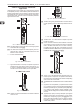
2.1.3 Aux/FX send buses
Aux sends enable you to take the signals from one or multiple
channels and collect them on one bus. This signal is then present
at one of the aux send jacks, from where it can be routed to an
active monitor speaker or external effects device, for example.
The FX returns are subsequently used as a return bus for the
processed signal.
Fig. 2.3: AUX/FX send controls in the channel strips
{9} On each channel, the AUX 1 and AUX 2 controls allow
you to determine the level of the aux signals sent from the
channel. The main aux send signal comprising the aux send
signals from all channels can then be adjusted with the corresponding master AUX SEND controls (51), and is present
at the AUX SEND outputs (52). Both aux sends are mono,
post-EQ, with a gain of up to +15 dB.
(10) Press the PRE switch to set all aux sends to pre-fader. In
this case, the volume of the aux signals is no longer dependent on the fader position, so you can create completely
independent monitor mixes.
Control elements and connections
5
EURODESK SL3242FX-PRO/SL2442FX-PRO
++ For most applications when controlling an external effects device from one of the aux buses, the aux sends
must be set post-fader, so that the effect volume in a
channel depends on the position of the channel fader.
Otherwise, the effect signal would still be audible, even
if the channel was turned down completely. For this type
of application it is advisable to leave the PRE switch out
(= not pressed).
(11) FX 1 and FX 2 controls provide a direct route to the built-in
effects processor. Additionally, they can be used to control
an external effects unit, via the FX SEND 1 and 2 outputs
(similar to the AUX SEND 1 and 2 jacks). To ensure that the
internal effects processor and the FX SEND outputs actually get a signal, the corresponding FX control must not be
set fully counter-clockwise (-oo), and the master FX SEND
(see (60)) must be turned up. The FX buses are hard wired
post-fader.
(16) The SUB switch routes the signal to the respective subgroups. Your EURODESK features 4 subgroups (1-2 and
3-4). With the PAN control on the input channel (see (12))
you can determine to which of the two groups the signal is
routed (hard left: sub 1 or 3, hard right: sub 2 or 4).
(17) The MAIN switch routes the signal to the main mix.
(18) The channel fader governs the level of the channel signal
as part of the main mix (or submix).
2.2 Stereo channels
2.2.1 Channel inputs
++ Please also read chapter 2.10 “Effects section” and3
“DIGITAL EFFECTS PROCESSOR”.
2.1.4 Mono channel fader and further control
elements
Fig. 2.5: Stereo channel inputs
(19) Each stereo channel is equipped with two balanced line-level
inputs on 1/4" TRS connectors for the left and right channels.
The channels can also process mono signal, as long as you
use the “LEFT” jack only.
(20) All stereo channel strips have a TRIM control for gain adjustment. Its scale ranges from +20 to -20 dB and allows you to
adapt the input level to the line inputs.
2.2.2 Stereo channel equalizer
Fig. 2.4: Channel fader, pan control, mute button, etc.
(12) The PAN control determines the position of the channel
signal in the stereo mix as well as the subgroup to which
the channel signal is routed (see chapter 2.4).
(13) Use the MUTE switch to mute the channel signal, so it is no
longer part of the main mix. At the same time, all aux buses
set to post-fader are muted for the respective channel, while
the pre-fader monitor buses remain operative. The MUTE
LED is illuminated when the channel is muted.
(14) The CLIP LED illuminates when the channel overloads.
In this case, please reduce the input gain using the TRIM
control. This LED also illuminates when you activate the solo
function with the SOLO switch below.
(15) The SOLO switch routes the channel signal to the solo bus
(Solo In Place) or the PFL bus (Pre Fader Listen). Thus,
you can monitor a channel signal without affecting the main
output signal. The signal to be monitored is taken either pre
(PFL, mono) or post-panorama control (Solo, stereo) and
post-channel fader (depending on the position of the SOLO/
PFL switch (40)).
6
Fig. 2.6: Stereo channel equalizer
The stereo channels are equipped with a stereo equalizer. The
filter types and cutoff frequencies for HIGH and LOW filters are
the same as on the mono channels. Instead of one semi-paramtric
midrange band, the stereo channels have two separate midrange
bands ((21) HIGH MID and LOW MID) with fixed mid-frequencies
(3 kHz and 400 Hz). Stereo EQs are preferable for processing the
frequency response of stereo signals. With two mono equalizers
you might encounter problems with different settings between the
left and right channels.
2.2.3 Stereo channel aux/FX send buses
Basically, the aux and FX buses on the stereo channels are the
same as on the mono channels. Since aux buses are always mono,
the signal from a stereo channel is first mixed to mono before it
is routed to the aux bus.
Control elements and connections
EURODESK SL3242FX-PRO/SL2442FX-PRO
2.4 Subgroups 1 - 4
2.2.4 Stereo channel fader and othercontrol elements
Fig. 2.9: Subgroups 1 - 4
Fig. 2.7: Channel fader, balance control, mute switch, etc.
(22) The BAL(ANCE) control has the same function as the PAN
control on the mono channels. It determines the relative
volume of the left and right input signals before they are
routed to the stereo main mix bus (or to two subgroups).
All other control elements of the stereo channels work in the same
ways as their counterparts on the mono channels (faders, MUTE
switches, etc.).
++ Please note: When you route a stereo channel to the
subgroups using the SUB switches, please be sure to
set the BAL control to its mid position, so that the signal
is sent to two subgroups and remains stereo.
2.3 Stereo channels 21 - 24 (SL2442FX-PRO)
or 29 - 32 (SL3242FX-PRO)
The EURODESK has 4 subgroups enabling you to create mono or
stereo mixes from multiple input signals. Subgroups are controlled
from one (mono) or two (stereo) subgroup faders. Additionally, it
is possible to connect the subgroup outputs as tape sends to a
multi-track recorder.
(25) The subgroup faders determine the volume of the subgroup
signal at the subgroup output (28). Depending on the position
of the routing switch (27) you can thus control the subgroup
volume in the main mix.
(26) The SOLO switch routes the subgroup signal to the solo
bus (Solo In Place) or PFL bus (Pre Fader Listen), so that
you can monitor the subgroup signal without affecting the
main or sub output signals. The signal to be monitored is
taken either pre (PFL, mono) or post-subgroup fader(Solo,
stereo), depending on the position of theSOLO/PFL switch
(40)). The SOLO LED illuminates when the SOLO switch is
pressed.
(27) Use the routing switches for the subgroups to send the
subgroup signal to the main mix. You can route it to the
left stereo side (=LEFT pressed), to the right stereo side
(=RIGHT pressed) or to both (=LEFT and RIGHT pressed).
For example, when you have created a stereo submix using
subgroups 1 and 2, be sure to route group 1 to the left and
group 2 to the right side to maintain proper stereo positioning. If it is a mono submix with just one subgroup, route it to
the left and right sides of the main mix to make the signal
audible on both sides.
Fig. 2.8: Auxiliary stereo channels
Your EURODESK has two stereo channels with an aux send
section ((23) AUX 1 and AUX 2) and one LEVEL control (24). For
these channels, the aux buses are hard-wired to pre-fader and are
therefore particularly useful for monitoring. They have no routing
switches and are always sent to the main mix. Like the normal
stereo channels they have two line-level inputs on1/4" TRS connectors for the left and right channels, and a SOLO switch.
Fig. 2.10: Subgroup outputs 1 - 4
(28) These four SUBGROUP OUT (puts) carry the signals of the
individual subgroups. For multi-tracking connect the outputs
to the inputs of a multi-track recorder (see chapter 4.1 “Studio
set-up”).
Similar to the CD/TAPE inputs (see (49)) the auxiliary stereo
channels can be connected to CD players, tape decks, etc., for
example, to feed in playback material.
Control elements and connections
7
EURODESK SL3242FX-PRO/SL2442FX-PRO
2.5 Mono out section for subwoofer
applications
Using this auxiliary mono output you can route the main mix signal
to a separate power amp. The tunable low-pass filter allows you to
limit the signal content to the low-frequency range to get a perfect
subwoofer signal. This signal is mono because very low frequencies disperse quickly, so there would be no benefit to position this
signal in the stereo mix.
Fig. 2.14: XLR main out connectors
(34) The MAIN OUT(puts) are balanced XLR connectors with a
nominal operating level of +4 dBu and provide the main mix
signal.
Fig. 2.15: Main out connectors and main insert
(35) The MAIN OUT 1/4" TRS connectors outputs also provide
the main mix signal.
Fig. 2.11: Mono out fader and low-pass filter
(29) The MONO fader controls the volume of the signal present
at the MONO OUT (see (32)).
(30) The FREQ control adjusts the cut-off frequency of the lowpass filter (30 to 200 Hz). Frequencies above cut-off are
filtered out when activated.
(36) Like the channel inserts, the MAIN INSERT connectors
can be used to connect a dynamics processor or equalizer
for further processing of the mix signal. The MAIN INSERT
refers to the Main Outs (XLR and 1/4" TRS connectors),
the MONO OUT (see (32)) and, if the MAIN switch in the
PHONES/CONTROL ROOM section is pressed, also to the
PHONES/CTRL ROOM output (see (46)).
(31) Use the LOW PASS FILTER switch to activate the filter
function (LED illuminates).
Fig. 2.12: Mono out connector
(32) The MONO OUT connector provides the line-level mono
signal for connection to the inputs of a power amp or active
speaker. You can also use this output as a monitor bus, e.g.
to connect a headphone amplifier. In this case, the signal
should of course not be limited by the low-pass filter.
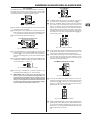
2.6 Main out section
Fig. 2.16: Level meter
(37) The red “+48 V” LED illuminates when phantom power is on.
Phantom power is required for the operation of condenser
microphones, and can be switched on with the corresponding
switch on the rear of the console.
(38) The POWER LED is illuminated when the console is switched
on.
(39) The high-precision level meter accurately indicates the output
signal level. For example, when you press the SOLO switch
on one of the input channels, its signal level will be displayed
here, either pre-fader (PFL) or post-fader (SOLO), depending
on the position of the SOLO/PFL switch (see (40)). In PFL
mode only the left display is active, because the PFL signals
are mono.
Fig. 2.13: Main out fader
(33) Use this high-precision MAIN fader to control the output level
of the main mix.
8
(40) The SOLO/PFL switch determines whether the monitored
signal is pre (PFL) or post-fader (SOLO) after pressing the
SOLO/PFL switch (the LED illuminates). The level meter
indicates the corresponding signal (see (39)). When you
adjust a signal with the TRIM control, it is advisable to select
PFL mode, so that the level shown is independent of the
channel fader position.
Control elements and connections
EURODESK SL3242FX-PRO/SL2442FX-PRO
2.7 CD/tape
2.6.1 Talkback
The talkback function of the EURODESK allows you to communicate with the musicians in the recording room or on the stage.
The talkback signal is present at the AUX SEND outputs, which
are particularly useful for monitor/headphone mixes.
Fig. 2.20: CD/tape
(47) TO MAIN controls the volume of, for example, a CD player
connected to the CD/tape input connectors (see (49)).
Fig. 2.17: Talkback section
(41) The LEVEL control determines the volume of the talkback
signal at the AUX 1/2 outputs.
(42) Use the TALK TO AUX 1/2 switch to activate the built-in talkback microphone. Its signal is sent to the AUX SEND jacks
1 and 2. Keep the switch pressed while you’re speaking.
(48) When the STANDBY switch is pressed, all input channels
are muted. Only the CD/tape signal will be routed to the
main mix. In this way, you can prevent the microphones from
pickung up unwanted sounds or noise that would interfere
with CD playback during a break. The main mix and channel faders can remain in their normal positions while playing
back music from CD (using the CD/TAPE INPUTs (49)), so
you don’t lose your mix.
(43) This is the built-in talkback microphone.
2.6.2 Phones & control room
Fig. 2.21: CD/tape connectors
Fig. 2.18: Phones/control room section
(44) The PHONES/CTRL R control adjusts the volume of the
headphones connected to the PHONES/CTRL ROOM OUT
jack (see (46)). If you have an active monitor speaker or
power amp connected here, you can also control the monitor
volume.
(45) These switches select the signal sent to the PHONES/CTRL
ROOM jack. Available sources are: MAIN, CD/TAPE, AUX
1/2 and subgroups 1 - 2 and 3 - 4.
(49) The CD/TAPE INPUT RCA connectors are for the connection
of CD players, tape decks or other line-level sources. The
signal volume is adjusted with the TO MAIN control.
(50) The CD/TAPE OUTPUT RCA connectors provide the stereo
main mix signal to a tape deck or DAT recorder to record
your mix. The signal is taken pre-fader, so that it will not be
influenced by the fader positions.
2.8 Master aux send 1 and 2
Fig. 2.19: Phones/control room output
(46) Connect your headphones or monitor speaker to the
PHONES/CTRL ROOM OUT 1/4" TRS connector.
++ IMPORTANT! High volume levels may damage your
hearing and/or your headphones/loudspeakers. To
avoid switch-on/off thumps from the console and any
downstream devices, always make sure that the power
amp(s) or active speaker(s) are the last components that
are switched on and the first to be switched off. Always
make sure that the appropriate volume is set.
Fig. 2.22: Master aux sends
(51) These are the master AUX SEND controls 1 and 2 for adjusting the volume level sent to the corresponding aux send
connectors (see (52)). This way, you can control the mix of
all AUX 1 or AUX 2 signals of the input channels. The AUX
SEND section also has a SOLO switch.
Fig. 2.23: Master aux send outputs
(52) Use the AUX SEND outputs 1 and 2 to take the masterAUX
SEND signals and route them to an external effects device
or your monitor speakers. Subsequently, you can return the
effect signal, e.g. via the STEREO FX RETURN inputs (see
(67)) or specific input channels.
Control elements and connections
9
EURODESK SL3242FX-PRO/SL2442FX-PRO
2.9 Graphic 9-band stereo equalizer
(59) The EffeCt displays show the currently selected presets.
(60) This is the master FX 1 (or 2) SEND control for adjusting
the volume of all FX send signals at the correspondingFX
send jacks (see (66)) and at the inputs of the built-in effects
processor. Use it to control the master signal of allFX 1/FX
2 signals from the input channels. When neither of the FX
SEND controls is turned up, the effects processor will not
receive a signal.
(61) Turn the FX 1 (or FX 2) control to select an effects preset.
Then, push it briefly to confirm your selection and activate
the new effect.
Fig. 2.24: The graphic stereo equalizer
(53) Your EURODESK is equipped with a graphic 9-band stereo
equalizer processing either the main or the AUX 1 signal.
Use the EQ to adapt the sound to the room acoustics.
(54) Use the EQ IN switch to switch the equalizer on. In this case,
the fader LEDs illuminate.
(55) With the MAIN/AUX 1 switch you can determine the signal
to be processed, either main or AUX 1.
(56) Press the FBQ IN switch to activate the FBQ Feedback
Detection System. The frequencies causing feedback are
indicated by the brightly lit fader LEDs, while all other LEDs
are darker. Simply lower the level of the brightly lit faders
until feedback disappears.
++ When the switch is in the “AUX 1” position (see (55)),
the EQ fader LEDs show both the MAIN and the AUX
1 signal simultaneously. However, if feedback occurs
in one of the signals, those signals without feedback
will be faded out to enable clear identification of where
feedback is occurring. If the MAIN signal happens to be
the one carrying feedback, put the switch (55) to “MAIN”
and then use the 9-band EQ to remove the feedback.
(62) The FX 1 (or 2) TO AUX 1 controls allow you to add the effect
signal from the built-in effects processor (FX1 or FX2) to the
AUX 1 monitor signal. Naturally, the effects processor must
be provided with an input signal (i.e. the FX controls in the
channel strips plus the FX SEND controls and the channel
faders must be turned up).
(63) This is the FX 1 (or 2) TO AUX 2 control adding the effect
signal from the effects processor to the AUX 2 monitor signal.
See (62) for further details.
(64) The FX 1 (or 2) TO MAIN control routes the effect signal
either to the main mix or the subgroups 1 and 2 (or 3 and 4),
depending on the position of the selector switch (see (65)).
When it is hard left, no effect signal will be audible. Here,
too, the FX controls in the channel strips plus theFX SEND
controls and the channel faders must be turned up.
(65) These selector switches route the effect signal to the main
mix or to the subgroups 1-2 or 3-4. If the MAIN/SUB switch
is not pressed, the effect signal is sent to the main mix and
the SUB 1/2 / SUB 3/4 switch below is inoperative. If the
upper switch is pressed (SUB), however, the lower switch
determines whether the effect signal is routed to subgroups
1 and 2 (SUB 1/2) or 3 and 4 (SUB 3/4).
2.10 Effects section
Fig. 2.26: FX send and return connectors
(66) The FX SEND 1 and 2 connectors also provide the master FX
send signals, for example, to connect them to the inputs of an
external effects device. However, these are “dry” signals only
with no “effect signals” from the built-in effects processor!
(67) The Stereo FX RETURN inputs 1 and 2 return the effect
signals from external effects processors and add them to
the main mix.
Fig. 2.27: Footswitch connectors
Fig. 2.25: The digital effects processor
(57) Here you will find a list of all multi-effects presets (see also
chapter 3 “DIGITAL EFFECTS PROCESSOR”).
(68) The FOOTSW(ITCH) connector allows you to connect a
standard dual footswitch to separately enable/disableFX 1 or
FX 2. The tip of the 1/4" plug controls FX 1, the ring controls
FX 2.
(58) The FX LED level meters show the effects processor’s
input signal. Be sure that the clip LED only illuminates with
signal peaks. If it is lit all the time, the effects processor is
overloading and hence producing unpleasant distortion.
10
Control elements and connections
EURODESK SL3242FX-PRO/SL2442FX-PRO
3. Digital effects processor
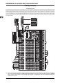
2.11 Rear panel
Fig. 3.1: List of all effects presets
99 FIRST-CLASS PRESETS
Fig. 2.28: The rear panel of the EURODESK
(69) Use the POWER switch to put the mixer into operation.
This switch should always be in the “Off” position when you
connect your unit to the mains.
++ Please note: The POWER switch does not fully disconnect the unit from the mains. To disconnect the unit
from the mains, pull out the main cord plug or appliance coupler. When installing the product, ensure the
plug or appliance coupler is readily operable. Unplug
the power cord when the unit is not used for prolonged
periods of time.
(70) With the PHANTOM switch you can activate the phantom
power supply for the XLR connectors of the mono channels
for condenser microphones. The +48 V-LED (37) illuminates
when phantom power is on. In most cases, dynamic microphones can still be used as long as they are connected in
a balanced configuration. If in doubt, please contact the
manufacturer of your microphone!
(71) The mains connection is a standard IEC receptacle. An appropriate power cord is supplied with the unit.
(72) FUSE HOLDER. Before connecting the unit to the mains,
ensure that the voltage setting matches your local voltage.
Blown fuses should only be replaced by fuses of the same
type and rating. Please also read the information given in
chapter 6 “SPECIFICATIONS”.
(73) SERIAL NUMBER.
Here is the list of all multi-effects presets. The built-in
effects processor offers you various standard effects
such as reverb, chorus, flanger, delay and a variety
of combination effects from our renowned studio
effects processor VIRTUALIZER PRO DSP2024P.
Use theFX control on the channels and the FX SEND control to
supply the effects processor with signals. A built-in digital stereo
effects processor has the benefit of no external wiring, thus reducing the risk of ground loops or level differences. Handling is
therefore much easier.
PARALLEL FX
The effects presets 1 to 70 provide classic “add-to-mix” effects. So,
when you turn up the FX 1 (or 2) TO MAIN control, you create a
mix of the (dry) channel signal and the effect signal. The balance
between the two signals can be set with the FX send and FX 1/2
TO MAIN controls.
This also applies to adding effect signals to the AUX 1 (or 2) monitor mix, with the exception that the mix here is adjusted with the
AUX 1 (or 2) control in the channel strip and the FX TO AUX 1 (or
2) potentiometer. Of course, the effects processor must receive
a signal from the channel using the FX 1 (or 2) control. Make
sure that the PRE switch in the corresponding channel strip(s) is
pressed. Otherwise, the AUX buses will be set post-fader making
the volume of the AUX monitor signal dependent on the position
of the channel fader(s).
INSERT FX (channel is muted)
Effects presets #71 and higher process the entire signal, unlike
the “add-to-mix” effects. When you use an insert preset, be sure
to separate the respective channel from all buses (SUB button
and MAIN button not pressed) and only route the effect signal to
the main mix (FX 1/2 control, FX SEND 1/2 control and FX TO
MAIN 1/2 control).
++ The channel fader of the corresponding channel remains
active and governs (in combination with the FX controls)
the signal level sent to the built-in effects processors.
Digital effects processor
11
EURODESK SL3242FX-PRO/SL2442FX-PRO
4. Wiring examples
4.1 Studio set-up
The following wiring example shows a studio set-up for 4-track-recording: the drums are mixed down to two subgroups and then
routed via the subgroup outputs to two tracks of the multi-track recorder. The remaining two subgroups are used to record the guitar,
keyboard (stereo channel) and two vocal signals on the remaining two tracks. The four return paths from the recorder are connected
to four separate mono input channels on the EURODESK. The built-in compressor is used only for the bass, which is why this input
channel is separate from all buses (SUB and MAIN switch not pressed). The bass signal is directly routed from the built-in effects
processor to the respective subgroups (FX TO MAIN control). The MAIN/SUB switch in the FX1 section is pressed, but NOT the SUB
1/2 SUB 3/4 button.
Fig. 4.1: Wiring the console for studio operation
++ Please make sure that none of the subgroup routing switches (1-2 and 3-4) is pressed in the channels connected to
the recorder returns. Otherwise, a feedback loop will be created as soon as you start recording. Only press the MAIN
switch on these input channels, so that the tape return signals are routed to the main outs and Phones/CTRL room
outputs of the console.
12
Wiring examples
EURODESK SL3242FX-PRO/SL2442FX-PRO
4.2 Live set-up
Fig. 4.2: Wiring the console for live operation
This example shows a classic live set-up. As in the studio example, four drum microphones, bass, keyboard (stereo channel), guitar
and two vocal microphones are connected. The four drum channels (kick drum, snare, overhead L, overhead R) are mixed down to
two subgroups and then routed to the main mix. This way, it is possible to conveniently control the volume of the entire drums in the
main mix with the two subgroup faders. The built-in compressor insert effect is used for the bass. The corresponding input channel is
separate from all buses and the bass signal is routed directly from the internal effects processor to the main mix bus. The MAIN/SUB
switch must not be pressed in this case and the position of the SUB 1/2 SUB 3/4 switch is irrelevant.
Wiring examples
13
EURODESK SL3242FX-PRO/SL2442FX-PRO
5. Audio connectors
The inputs and outputs of the BEHRINGER EURODESK are
designed as unbalanced 1/4" TS connectors—except for the balanced line inputs of the mono and stereo channels and the main
out connectors. Of course, all inputs and outputs work with both
balanced and unbalanced connectors. The tape ins and outs are
stereo RCA connectors.
++ Please ensure that only qualified personnel install and
operate the EURODESK. During installation and operation, the user must have sufficient electrical contact to
earth. Electrostatic charges might affect the operation
of the unit.
Fig. 5.5: ¼" TS footswitch connector
Fig. 5.1: ¼" TS connector
Fig. 5.6: ¼" TRS connector for headphones
Fig. 5.2: ¼" TRS connector
Fig. 5.7: Insert send and return ¼" TRS connector
Fig. 5.3: RCA cable
Fig. 5.4: XLR connectors
14
Audio connectors
EURODESK SL3242FX-PRO/SL2442FX-PRO
6. Presets
Effect
Description
PARALLEL EFFECTS
Cathedral
Very dense and long reverberation of a large cathedral.
Plate
Simulates the sound of early plate reverberators.
Concert
Simulates a small theater or large concert hall.
Stage
Very dense reverb, especially for live applications.
Room
You can clearly hear the walls of the room.
Adds spaciousness to the sound; signals sound natural, not
Studio
"flat".
Small Hall
Simulates a small, lively (strongly reflecting) hall.
Ambience
Reproduces a middle-sized room without late reflections.
Early Reflections
Very dense reverb with pronounced early reflections.
Spring Reverb
Simulates a classic spring reverberation.
Gated Reverb
Reverb that is synthetically cut off
Reverse Reverb
Reverb with reversed envelope, i.e. it slowly gets louder.
Application examples
Solo instruments / vocals in slow pieces.
A classic for drums (snare) and vocals.
Creates an "atmosphere" (e.g. radioplay voices).
Dissipates the sound of keyboard pads, for example.
Reverb effect that isn't directly noticeable.
Gives a sound source more "class" in the mix.
Chorus
Slight detuning of the original signal.
Flanger
A slightly delayed signal is added to the original signal,
producing phase shifting of the signals.
Phaser
Another phase-shift effect.
Rotary Speaker
Delay
Chorus & Reverb
Flanger & Reverb
Phaser & Reverb
Rotary Speaker &
Reverb
Simulation of a classic effect for electronic organ.
Delay of the input signal with several repetitions.
Combination of chorus and reverb.
Flanger combined with a reverb effect.
Phaser combined with a reverb effect.
Perfect for processing drums.
Extremely versatile effect.
Drums, percussion, slap bass
Extremely versatile effect.
Produces a very "crisp" snare sound.
Produces a very spaced out vocal sound.
Extremely versatile effect (guitar, vocals, bass, keyboards etc.).
Extremely versatile effect (guitar, vocals, bass, keyboards etc.).
Extremely versatile effect (guitar, vocals, bass, keyboards etc.).
Organ / keyboards.
Extremely versatile effect.
A classic effect for vocals.
All-purpose effect.
All-purpose effect.
Rotary Speaker effect combined with reverb.
Organ/keyboards/electric guitar.
Delay & Reverb
Delay combined with reverb.
Delay & Chorus
Delay & Flanger
Widens the signals and produces interesting repetition
effects.
Similar to Delay & Chorus, but with audible up/downward
modulation.
The most common combination for vocals, solo guitar,
etc.
Makes vocals stand out in the mix. Good intelligibility is
preserved.
Ideal for creating a slightly spaced out sound.
INSERT EFFECTS
Compressor
Expander
Gate
Ultramizer
Ultrabass
Panner
Exciter
Auto Filter
Tube Distortion
Guitar Amp
Vinylizer
Test Tone
Soft or loud passages are raised or lowered in level
respectively.
No dynamics limitation (see Compressor), but quite the opposite: interference (noise, hum, etc.) is reduced in level.
A gate opens for a specific period of time to make a specific
signal pass, and then closes abruptly.
Extremely efficient compression through automatic adaptation of compression parameters.
Combines sub-harmonics processor, bass exciter and
limiter.
The signal "wanders" between the sides of the stereo basis.
Adds synthetic harmonics to the signal, resulting in increased presence and "loudness".
Level-dependent boost of a specific frequency band, similar
to auto-wah effect for electric guitars.
Simulates the tube distortion of classic guitar amplifiers.
Guitar amp simulation.
Adds the clicks and noise of old vinyl records.
1-kHz test tone.
Presets
Single signals, especially from microphones.
Single signals, especially from microphones.
"Controls" feedback-prone microphones / eliminates
interference.
Gives mix signals a constant output level.
Gives keyboard sounds some special "class" / sound
effect for electric basses.
Special effect, e.g. for radioplay soundtracking.
Both mix and single signals. Improves intelligibility of
vocal signals.
DJ-ing / sound effects for live events / electric guitar or
bass.
Electric guitar / vocals / keyboards.
Electric guitar or bass.
DJ-ing / sound effects for live events.
Makes P.A. level setting easier.
15
EURODESK SL3242FX-PRO/SL2442FX-PRO
7. Specifications
Subgroup outputs
Type
Impedance
Max. output level
Mono inputs
Microphone inputs (IMP “Invisible” Mic Preamp)
Type
Mic E.I.N.1(20 Hz - 20 kHz)
@ 0 Ω source resistance
@ 50 Ω source resistance
@ 150 Ω source resistance
Frequency response
<10 Hz - 160 kHz
<10 Hz - 200 kHz
Gain range
Max. input level
Impedance
Signal-to-noise ratio
Distortion (THD+N)
Line input
Type
Impedance
Gain range
Max. input level
XLR connector, electronically balanced,
discrete input circuit
-134 dB / 135.7 dB A-weighted
-131 dB / 134 dB A-weighted
-129 dB / 130.5 dB A-weighted
Main fader closed
Channel muted
Channel fader muted
Frequency response (Mic In → Main Out)
<10 Hz - 70 kHz
<10 Hz - 130 kHz
Stereo inputs
Type
Impedance
Gain range
Max. input level
CD/Tape in
Type
Impedance
Max. input level
LOW
MID
HIGH
LOW CUT
EQ stereo channels
LOW
LOW MID
HIGH MID
HIGH
Channel inserts
Type
Max. input level
AUX/FX Send
Type
Impedance
Max. output level
FX Returns
Type
Impedance
Max. input level
16
Type
Impedance
Max. output level
Main Inserts
Type
Max. input level
Mono output
Type
Impedance
Max. output level
Low pass
Phones/CTRL room output
Type
Max. output level
CD/Tape Out
Type
Impedance
Max. output level
+0 dB / -1 dB
+0 dB / -3 dB
2 x ¼" TRS jack, balanced
approx. 20 kΩ balanced, 10 kΩ
unbalanced
-20 dB to +20 dB
+22 dBu @ 0 dB GAIN
DSP
Type
Converter
Sampling rate
80 Hz / ±15 dB
400 Hz / ±15 dB
3 kHz / ±15 dB
12 kHz / ±15 dB
Power consumption
Fuse (100 - 240 V~, 50/60 Hz)
Mains connector
¼" mono jack, unbalanced
approx. 10 kΩ
+22 dBu
¼" TRS jack, unbalanced
+22 dBu
¼" mono jack, unbalanced
approx. 120 Ω
+22 dBu
variable30 Hz to 200 Hz, 18 dB/oct.
¼" TRS jack, unbalanced
+19 dBu / 150 Ω (+25 dBm)
RCA connector
approx. 1 kΩ
+22 dBu
Texas Instruments
24-bit delta-sigma, 64/128-times
oversampling
46 kHz
50 W
T 2.0 A H 250 V
Standard IEC receptacle
Physical/weight
SL3242FX-PRO
Dimensions (H x W x D)
Weight (net)
3.9" x 35.3" x 16.1" (100 mm x 896 mm
x 410 mm)
25.4 lbs (11.5 kg)
SL2442FX-PRO
Dimensions (H x W x D)
¼" TRS jack, unbalanced
+22 dBu
¼" mono jack, unbalanced
approx. 120 Ω
+22 dBu
¼" TRS jack, electronically balanced
approx. 240 Ω balanced, 120 Ω
unbalanced
+28 dBu
Main mix @ -∞, channel fader @ -∞
-100 dB / -102.5 dB
A-weighted
Main mix @ 0 dB, channel fader @ -∞
-82 dB / -85 dB A-weighted
Main mix @ 0 dB, channel fader @ 0 dB -72 dB / -75 dB A-weighted
Power supply
80 Hz / ±15 dB
100 Hz - 8 kHz / ±15 dB
12 kHz / ±15 dB
80 Hz, 18 dB/oct.
XLR connector, electronically balanced
approx. 240 Ω balanced, 120 Ω
unbalanced
+28 dBu
Main mix system data3(Noise)
RCA connector
approx. 10 kΩ
+22 dBu
Equalizer
EQ mono channels
Main outputs (¼")
¼" TRS jack, electronically balanced
approx. 20 kΩ balanced, approx. 10 kΩ
unbalanced
-10 dB to +40 dB
+22 dBu @ 0 dB GAIN
90 dB
84 dB
85 dB
Type
Impedance
Max. output level
-1 dB
-3 dB
+10 dB to +60 dB
+12 dBu @ +10 dB GAIN
approx. 2.6 kΩ balanced
110 dB / 112 dB A-weighted (0 dBu In @
+22 dB GAIN)
0.004 % / 0.003 % A-weighted
Fade-out attenuation2(Crosstalk attenuation)
Main outputs (XLR)
¼" mono jack, unbalanced
approx. 120 Ω
+22 dBu
Weight (net)
3.9" x 26.9" x 16.1" (100 mm x 682 mm
x 410 mm)
18.8 lbs (8.5 kg)
1
Equivalent Input Noise
2
Measuring conditions: 1 kHz rel. to 0 dBu; 20 Hz - 20 kHz; line input; main output;
unity gain.
3
20 Hz - 20 kHz; measured at main output. Channels 1 - 4 unity gain; EQ flat; all channels on main mix; channels 1/3 as far left as possible; channels 2/4 as far right as
possible; reference = +6 dBu.
BEHRINGER is constantly striving to maintain the highest professional standards.
As a result of these efforts, modifications may be made from time to time to existing
products without prior notice. Specifications and appearance may differ from those
listed or illustrated.
Specifications
EURODESK SL3242FX-PRO/SL2442FX-PRO
8. Warranty
§ 1 Other warranty rights and national law
1. This warranty does not exclude or limit the buyer’s statutory rights
provided by national law, in particular, any such rights against the seller
that arise from a legally effective purchase contract.
2. The warranty regulations mentioned herein are applicable unless
they constitute an infringement of national warranty law.
§ 2 Online registration
Please do remember to register your new BEHRINGER equipment right
after your purchase by visiting http://www.behringer.com and kindly
read the terms and conditions of our warranty carefully. Registering
your purchase and equipment with us helps us process your repair
claims quicker and more efficiently.
Thank you for your cooperation!
§ 3 Warranty
1. BEHRINGER (BEHRINGER International GmbH including all
BEHRINGER subsidiaries, except BEHRINGER Japan) warrants
the mechanical and electronic components of this product to be free
of defects in material and workmanship for a period of one (1) year*
from the original date of purchase, in accordance with the warranty
regulations described below. If the product shows any defects within
the specified warranty period that are not excluded from this warranty
as described under § 5, BEHRINGER shall, at its discretion, either
replace the product by providing a new or reconditioned product or
repair the product using suitable new or reconditioned parts. In the
case that other parts are used which constitute an improvement,
BEHRINGER may, at its discretion, charge the customer for the additional cost of these parts. In case BEHRINGER decides to replace
the product, this warranty shall apply to the replacement product for
the remaining initial warranty period, i.e one year* from the date of
purchase of the initial product.
2. If the warranty claim proves to be justified, the product will be
returned to the user freight prepaid.
3. Warranty claims other than those indicated above are expressly
excluded.
§ 4 Return authorization number
1. To obtain warranty service, the buyer (or his authorized dealer) must
call BEHRINGER during normal business hours BEFORE returning
the product. All inquiries must be accompanied by a description of
the problem. The buyer or his authorized dealer will receive a return
authorization number.
2. Subsequently, the product must be returned in its original shipping
carton, together with the return authorization number. The return shipment address will be indicated by BEHRINGER.
2. If the product needs to be modified or adapted in order to comply
with applicable technical or safety standards on a national or local
level, in any country which is not the country for which the product was
originally developed and manufactured, this modification/adaptation
shall not be considered a defect in materials or workmanship. The
warranty does not cover any such modification/adaptation, irrespective of whether it was carried out properly or not. Under the terms of
this warranty, BEHRINGER shall not be held responsible for any cost
resulting from such a modification/adaptation.
3. Free inspections and maintenance/repair work are expressly excluded from this warranty, in particular, if caused by improper handling
of the product by the user. This also applies to defects caused by normal wear and tear, in particular, of faders, crossfaders, potentiometers,
keys/buttons, tubes, guitar strings, illuminants and similar parts.
4. Damage/defects caused by the following conditions are not covered
by this warranty:
== improper handling, neglect or failure to operate the unit in
compliance with the instructions given in BEHRINGER user
or service manuals.
== connection or operation of the unit in any way that does not
comply with the technical or safety regulations applicable in
the country where the product is used.
== damage/defects caused by force majeure or any other condition
that is beyond the control of BEHRINGER.
5. Any repair or opening of the unit carried out by unauthorized personnel (user included) will void the warranty.
6. If an inspection of the product by BEHRINGER shows that the
defect in question is not covered by the warranty,
7. Products which do not meet the terms of this warranty will be repaired exclusively at the buyer’s expense. BEHRINGER will inform the
buyer of any such circumstance. If the buyer fails to submit a written
repair order within 6 weeks after notification, BEHRINGER will return
the unit. Costs for freight and packing will be invoiced separately
C.O.D. When the buyer has sent in a written repair order such costs
will also be invoiced separately.
§ 6 Warranty transferability
This warranty is extended exclusively to the original buyer (customer of
retail dealer) and is not transferable to anyone who may subsequently
purchase this product. No other person (retail dealer, etc.) shall be
entitled to give any warranty promise on behalf of BEHRINGER.
§ 7 Claim for damages
Failure of BEHRINGER to provide proper warranty service shall not
entitle the buyer to claim (consequential) damages. In no event shall
the liability of BEHRINGER exceed the invoiced value of the product.
* Customers in the European Union please contact BEHRINGER
Germany Support for further details.
3. Shipments without freight prepaid will not be accepted.
§ 5 Warranty regulations
1. Warranty services will be furnished only if the product is accompanied by a copy of the original retail dealer’s invoice. Any product
deemed eligible for repair or replacement under the terms of this warranty will be repaired or replaced.
Technical specifications and appearance are subject to change without notice. The information contained herein is correct at the time of printing. All
trademarks (except BEHRINGER, the BEHRINGER logo, JUST LISTEN and ULTRABASS) mentioned belong to their respective owners, and such
use neither constitutes a claim of the trademarks by BEHRINGER nor affiliation of the trademark owners with BEHRINGER. BEHRINGER accepts no
liability for any loss which may be suffered by any person who relies either wholly or in part upon any description, photograph or statement contained
herein. Colors and specifications may vary slightly from product. Our Products are sold through authorized dealers only. Distributors and dealers are
not agents of BEHRINGER and have absolutely no authority to bind BEHRINGER by any express or implied undertaking or representation. This manual
is copyrighted. No part of this manual may be reproduced or transmitted in any form or by any means, electronic or mechanical, including photocopying
and recording of any kind, for any purpose, without the express written permission of BEHRINGER International GmbH.
ALL RIGHTS RESERVED. © 2007 BEHRINGER International GmbH, Hanns-Martin-Schleyer-Str. 36-38, 47877 Willich-Muenchheide II, Germany. Tel.
+49 2154 9206 0, Fax +49 2154 9206 4903
Warranty
17