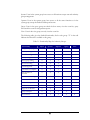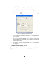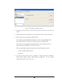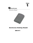
1
Volume
1
EverAccess
User’s Manual
FLEX Series Access Control
Management Software
Flex1.0
EVERFOCUS ELECTRONICS CORPORATION
Flex1.0
Instruction Guide
© 2004 Everfocus Electronics Corp
1801 Highland Ave Duarte CA 91010
Phone 626.844.8888 • Fax 626.844.8838
All rights reserved. No part of the contents of this manual may be reproduced or transmitted in any
form or by any means without written permission of the Everfocus Electronics Corporation.
Table of Contents
CHAPTER 1
Introduction ....................................................................................................................................... 1
About This Guide............................................................................................................................... 1
How to Use This Guide?............................................................................................................ 1
About the software ........................................................................................................................... 2
Program Layout.......................................................................................................................... 2
How to Start ............................................................................................................................... 3
System Requirements ............................................................................................................... 3
Basic Steps to Setup the System.................................................................................................... 4
CHAPTER 2
Installation ......................................................................................................................................... 5
Installation process .......................................................................................................................... 5
Uninstall the program ....................................................................................................................... 8
CHAPTER 3
Authority Management ................................................................................................................... 10
User and Authority Group............................................................................................................... 10
Manage Users and Authorities ...................................................................................................... 12
Adding a User........................................................................................................................... 12
Deleting a User ........................................................................................................................ 14
Edit User’s Properties ............................................................................................................. 15
CHAPTER 4
Controller Configuration ................................................................................................................. 16
Controller Configuration Dialog ..................................................................................................... 16
Add a Controller............................................................................................................................... 17
Delete a Controller .......................................................................................................................... 18
Update the Status of Controllers................................................................................................... 19
Configure a Controller..................................................................................................................... 19
Specify the Location of a Controller ...................................................................................... 19
Change the Serial Port for a Controller ................................................................................. 19
Configure Doors ....................................................................................................................... 20
Edit Door Location Information .............................................................................................. 20
Set Door Open Time ................................................................................................................ 21
Set Door Held Open Time ....................................................................................................... 21
Configure Readers ................................................................................................................... 22
Set Related Door...................................................................................................................... 22
Set Keypad and In/Out Properties.......................................................................................... 23
Set System Reader Property .................................................................................................. 23
Configure Alarms ..................................................................................................................... 24
Alarm Setting 1 Tab: ........................................................................................................ 25
Alarm Setting 2 Tab: ........................................................................................................ 25
Alarm Setting 3 Tab: ........................................................................................................ 27
Configure an Alarm .......................................................................................................... 29
Miscellaneous Configurations ................................................................................................ 31
Configure Fire Alarm Control .......................................................................................... 32
Enable/Disable Arm Zone Inputs .................................................................................... 33
Set System Time .............................................................................................................. 33
Enable Auto Daylight Saving Time ................................................................................. 34
Set Arm Delay Time ......................................................................................................... 34
Exit Controller Configurations................................................................................................ 34
CHAPTER 5
Holiday Setting ................................................................................................................................ 36
Date Types ....................................................................................................................................... 36
Recurrent Types.............................................................................................................................. 36
Date Type Setting Dialog................................................................................................................ 37
Add a Date........................................................................................................................................ 38
Edit a Date ....................................................................................................................................... 40
Delete a Date ................................................................................................................................... 40
Store Date Type Setting to Controllers......................................................................................... 40
CHAPTER 6
Access Group Setting ..................................................................................................................... 41
Introduction to Access Groups...................................................................................................... 41
Control Group Setting Dialog ......................................................................................................... 42
Configure an Access Group ........................................................................................................... 43
Select a Controller................................................................................................................... 43
Select an Access group .......................................................................................................... 43
Set Access to Doors ................................................................................................................ 43
Set Access Authority............................................................................................................... 44
"Apply to Days" Shortcut ........................................................................................................ 45
An Example Setup........................................................................................................................... 46
Download the setting data to controllers..................................................................................... 48
CHAPTER 7
Door Access Setting ....................................................................................................................... 49
Introduction to Door Access Settings........................................................................................... 49
Door Access Setting Dialog ........................................................................................................... 49
Configure Verification Level at Doors ........................................................................................... 51
Select a Controller................................................................................................................... 51
Select a Door............................................................................................................................ 51
Set Door Access ...................................................................................................................... 51
"Apply to Days" Shortcut ....................................................................................................... 51
"Apply to Doors" Shortcut....................................................................................................... 53
Example ........................................................................................................................................... 54
Download Door Access Setting to Controller............................................................................... 55
CHAPTER 8
Cardholder Management ................................................................................................................ 57
Enter Card Management Dialog Box ............................................................................................. 57
Card Management Toolbar ..................................................................................................... 59
Basic Steps for Setting up Cardholder Database................................................................. 60
Register Cards ................................................................................................................................. 60
Register Cards Manually ......................................................................................................... 60
Register Cards Automatically ................................................................................................ 61
Register Cards on Controller .................................................................................................. 62
Edit Card to Controller Relationship ............................................................................................. 62
Automatically Enroll Cards to Controllers ............................................................................ 63
Manually Apply Cards to Controllers ..................................................................................... 63
Remove Cards from Controllers ............................................................................................. 64
Edit Cardholders’ Profiles ............................................................................................................... 65
Edit Cardholders’ Profiles ....................................................................................................... 66
Select Cardholder’s Photo ...................................................................................................... 67
Filter Cardholders............................................................................................................................ 68
Edit Card Access Attributes........................................................................................................... 69
Edit Access Attributes of a card ............................................................................................ 69
Card Access Attributes Dialog ............................................................................................... 70
Edit Access Attributes of a batch of cards........................................................................... 72
Delete Card(s).................................................................................................................................. 74
Delete a card............................................................................................................................ 74
Delete All Cards ....................................................................................................................... 74
Cardholder Reports ......................................................................................................................... 75
Print Cardholder Reports ........................................................................................................ 75
Export Cardholder Reports in HTML format ......................................................................... 76
Export Cardholder Reports in Excel Format ......................................................................... 76
Edit Department List....................................................................................................................... 77
CHAPTER 9
Data Communication with Controller............................................................................................ 79
Downloading Data from the Computer to the Controller ............................................................ 79
Uploading Data from the Controller to the Computer ................................................................. 82
CHAPTER 10
Database Maintenance................................................................................................................... 85
Backup Database Files................................................................................................................... 85
Restore Database Files .................................................................................................................. 87
Purge Out-of-date Data ................................................................................................................... 89
CHAPTER 11
Event Log ......................................................................................................................................... 92
Event Logs Information .................................................................................................................. 92
View Event Logs.............................................................................................................................. 95
Sort Event Logs ............................................................................................................................... 97
Search Event Logs .......................................................................................................................... 98
Print Event Logs .............................................................................................................................. 99
Export Event Logs......................................................................................................................... 101
Event Warning Message ............................................................................................................... 101
CHAPTER 12
Device Control ............................................................................................................................... 104
Resources List............................................................................................................................... 104
Remote Arm/Disarm: ..................................................................................................................... 105
Remote Set/Reset the Alarm:....................................................................................................... 107
Remote Open Door........................................................................................................................ 107
CHAPTER 13
Adding Company Logo and Door Status Check ......................................................................... 110
Change Company Logo................................................................................................................. 110
Check Door Status ........................................................................................................................ 112
Notes .............................................................................................................................................. 115
Chapter
1
Introduction
This chapter describes the content of this user manual, and explains the fundamental
functionalities and the basic operations of the software. This chapter will present:
•
Basic information about this user’s manual
•
A basic introduction to the software
•
A basic introduction to the steps to setup the access control system.
About This Guide
The installation of an access control system can be divided into two major phases: the
hardware installation and the software configuration.
For installation information on the EverAccess Flex Series access control system’s
hardware, please refer to the EverAccess Flex controller manual for details and
instructions.
The software configuration is introduced in this guide, including how to use EverAccess
Flex Series Software, how to configure the whole access control system, how to check
the event log and how to remotely control the devices.
How to Use This Guide?
The guide basically follows the procedure to setup the whole access control system.
From adding a controller to the system to viewing the event logs, all details are
described in this guide, chapter by chapter. Reading the manual before installing the
system is recommended.
For first-time users of the EverAccess software, this introduction chapter is a must-read.
It provides an overall picture of the software, including items such as the system PC
requirements for the software, how to start the software and the basic steps to setup the
system in the software. After reading this chapter, users will be familiar with general
concepts of the software, and will have an idea of where to find more detailed
information that they might need in the future.
More experienced users can go directly to the relevant chapters to acquire the
information that they need for system configurations.
1
About the software
EverAccess Flex Series Software is designed to work with the EverAccess Flex series
access control hardware. The software provides a simple yet powerful interface to allow
system administrators and other users to manage the EverAccess system with ease and
flexibility.
The fundamental goal of EverAccess Flex software is to provide ease-of-use, so it is
designed in a very straightforward, simple-to-understand manner. The program layout
is described below.
Program Layout
Fig. 1.1 shows the main user interface of EverAccess Flex Series Software. The event
logs, system resources and the device remote control are shown in the main interface.
System
resources
Remote device
control
Event logs
Fig. 1.1 Program Layout
Fig. 1.2 shows the menu list under menu item “Management”. All major configurations
are listed under this menu. Click each menu item to bring up the dialog for each specific
configuration.
2
Fig. 1.2 Menu Items Under “Management”
The next section introduces how to start EverAccess Flex software.
How to Start
To start EverAccess Flex software on your computer, follow the steps below:
1. After the installation is complete, go to the “Start” menu Æ “All Programs” Æ
“EverAccess Flex Series Access Control System”. Click “EverAccess Flex
Software”.
2. A system login dialog box will appear after the initialization flash screen, to
prompt users to enter a name and password, shown as Fig. 1.3:
Fig. 1.3 Login Dialog Box
3. Type in the login name and the password, and click the Login button to enter
the software.
Note: Use login name “admin” and password “admin” to login to the system for
the first time. Remember to change the administrator password after the first login.
The system PC requirements for the software are explained in the next section.
System Requirements
In order to install and run EverAccess Flex software, the computer will need to have the
following minimum specifications:
Minimum requirements:
•
CPU: Pentium II 100MHz
•
Memory: 64M system RAM
3
•
Free hard drive space: 100M bytes free space
•
Screen resolution: 1024x768
•
An available serial port (in the event that the computer does not have a serial
port, a third party USB-to-Serial converter cable may be used.)
•
An available USB port (1.1 or above)
Basic Steps to Setup the System
In this section, the basic steps to setup the system will be addressed. The related chapter
in which detailed descriptions are outlined is given for reference.
To setup a new system, follow the basic steps below. Note that the procedure does not
have to be followed in the future when making system or maintenance changes.
1. Install the software. (Chapter 2)
2. Setup the users who will use the software and set the authority for these users.
(Chapter 3)
3. Add the controller(s) into the system. Based on the hardware installation and
wiring, configure the door, reader(s) and alarm(s) in the controller(s). (Chapter 4)
4. Build a plan of access rules:
a. Setup the holiday and other date types. (Chapter 5)
b. Setup the access groups and the access authority for each group.
(Chapter 6)
c. Setup the door access settings, such as unlock schedule, etc. (Chapter 7)
5. Setup the cardholder database (Chapter 8):
a. Enroll the cards
b. Edit cardholders’ profiles
c. Set card access attributes, such as access groups and so on.
6. Make sure the hardware wiring is correct. Now the system is ready to go. Users
can check the real-time event logs (Chapter 11) and remotely control the device
like doors from the main interface. (Chapter 12).
4
Chapter
2
Installation
The following chapter describes the installation procedure. The main objective of this
chapter is to explain:
•
How to install the software
Installation process
Insert the software CD into the management PC’s CDROM drive. On the PC, double
click on “My Computer”, and then on the appropriate drive for the CDROM. Now
double click “Setup.exe” in the software CD, and the following display should appear:
Fig. 2.1
To cancel the installation, simply click the cancel button shown in the dialog above.
Otherwise, the dialog box shown in the figure 1.2 will appear:
5
Fig. 2.2
If you wish to change the destination folder click “Browse” in this dialog. To continue
with the installation click “Next”. This will take you to the next step of the installation
as shown in the following figure:
Fig. 2.3
The program folder can be changed in this dialog box. For typical installations, use the
default program folder (EverAccessFlex). Click “Next” to continue the installation. Fig.
1.4 and Fig 1.5 show the dialog boxes indicating that the installation is complete.
6
Fig. 2.4
Fig. 2.5
Click “Finish” to complete the installation.
7
Uninstall the program
To uninstall the program, go to “Control panel” in Windows. Select “Add or Remove
Programs”, then choose “EverAccess Flex Software”. Click “Remove”, and the
following dialog box will appear.
Fig. 2.6
Select “Remove” and click “Next”. The software will prompt the user to confirm the
deletion as shown in the figure below:
Fig. 2.7
Click “Yes” to confirm the deletion, and all the program components will be removed
from the computer. A dialog box will appear to confirm that the deletion is complete, as
pictured below:
8
Fig. 2.8
9
Chapter
3
Authority Management
This chapter introduces the concept of managing users and authority groups in the
EverAccess Flex Software. In this chapter you will learn:
•
The definition of a user and an authority group
•
The authority groups provided in the software
•
The permissions for those groups
•
User management, including adding a user, deleting a user and editing the user
properties.
User and Authority Group
A User of Flex series access control software is a person who operates the software at
any user interface. Each user is defined by four properties: name, login name, password
and the authority group to which the user belongs.
The name should be the real name of the user. The login name is the identity that users
need to type into the login dialog to enter the system. The password is the password
that users need to provide when they login the system. The authority group will be
introduced below.
Please note that users are different from cardholders. Cardholders are the people who
enter or exit from the physical access control system, like a building or an area. But users
operate the software to monitor or configure the physical access control system.
The authority group defines the user’s access level over the operations in the software.
Different authority groups have different operating privileges in the software.
Flex series access control software offers five authority groups: Super, System, Operate,
Query, and View. There is no limit to the number of users in each group.
Super: Users in the super group can execute all the functionalities of the software. The
main functions include the user and authority group management, controller
configuration, holidays setting, access group setting, door zone setting, card
management, database backup and restore, etc.
10
System: Users in the system group have access to all functions except user and authority
group management.
Operate: Users in the operate group have access to all the same functions as in the
system group except the database backup and restore.
Query: Users in the query group can check the door status, view the event list, query
and search the event list and generate reports.
View: Users in the view group can only view the event list.
The following table gives the detailed functionality list for each group. “Y” in the cells
indicates the function is available to this group.
Table 3.1 Functionality Map for Authority Groups
Functionality
Super
System
Operate
Change company logo
Y
Y
Y
Authority management
Y
Controller configuration
Y
Y
Y
Holiday setting
Y
Y
Y
Access group setting
Y
Y
Y
Door zone setting
Y
Y
Y
Card management
Y
Y
Y
Upload data to computer
Y
Y
Y
Download data to
controller
Y
Y
Y
Communication setting
Y
Y
Y
Door status check
Y
Y
Y
Y
Database backup
Y
Y
Database restore
Y
Y
Purge out-of-date data
Y
Y
Query and report
Y
Y
Y
Y
View event list
Y
Y
Y
Y
11
Query
View
Y
Manage Users and Authorities
Click “Management” in the menu, and then click “Authority Management”. The user
and authority management dialog box will pop up, shown as below:
Function
button bar
User property
area
User list
Fig. 3.1 Authority management dialog
The top part in the dialog is the function button bar. The middle area shows the
properties of the selected user for the purpose of editing. The bottom area presents the
whole user list. The small black triangle at left indicates the currently selected user.
, button “Bw”
, button “Fw”
、button “BT”
are
The button “Top”
used to jump the first user record, the previous user record, the next user record and the
last user record, respectively. Alternatively, click on any user to designate it as the
currently selected one.
Adding a User
The basic steps to adding a user are explained below:
1. In the function bar, click the “Add” button
. After clicking the “Add”
button, the user interface in the figure below will appear. At this time, only the
user property area responds to the user’s operation until the editing is finished.
2. Fill in the user name and the login name. These will be used when logging in to
the system.
12
3. Enter a password. Retype it to confirm.
4. Select a group for this new user.
5. Click “OK” to add the new user. Click “Cancel” to exit without saving.
Fig. 3.2 Add a user
Please note that both passwords must be the same, otherwise an error message will be
displayed as shown in the following figure:
Fig. 3.3
Please note that the name of users can be left empty. But the login name cannot be
empty, since the login name is used for users to login the system. If users leave the login
name empty, after “OK” button is clicked, the following error message will be shown:
Fig. 3.4
13
Once the user is successfully added, the new user will be shown in the user list as
displayed in figure 2.5.
Fig. 3.5 A sample of a user added successfully
Deleting a User
To delete a user, follow the steps below:
1. Select the user to be deleted in the user list.
in the function button bar. A dialog will be shown
2. Click the “Del” button
to prompt users to confirm the deletion, as shown in next figure.
3. Click “Yes” to delete the user. Click “No” to cancel without deleting.
Fig. 3.6 Confirm message
14
Edit User’s Properties
In the browsing status, the properties in the user property area cannot be edited. To edit
a user’s property, follow these steps:
1. Select the user to be edited in the user list.
2. Click the “Edit” button in the user property area. When the dialog enters the
editing mode, any of the information can be edited. Please note that every user
must have a login name and password. At this time, only the user property area
respond to users’ operation until the editing operation is finished.
3. Click “OK” to confirm the editing and finish the editing operation. Click
“Cancel” to discard all the changes and return to the browsing mode.
Fig. 3.7 Edit a user’s property
15
Chapter
4
Controller Configuration
This chapter introduces how to configure a controller. In this chapter you will learn:
•
How to add or delete a controller in the software.
•
How to configure a controller.
Controller Configuration Dialog
To configure the controller, click “Management” in the menu, then click “Controller
Configuration”, the controller configuration dialog box will appear as shown in the
figure below:
Controller
setting area
Function
button bar
Controller list
Fig. 4.1 Controller configuration dialog Status bar
16
There are four basic areas in the controller configuration dialog box:
The function button bar is located at the top left, and provides the basic operation to
the controllers. The functions for the buttons
、
、
、
are adding a
controller, deleting a controller, search for all the listed controllers and refresh a
specified controller, respectively.
The controller list is located at the bottom left. It shows the basic information of a
controller, such as the RS485 address of the controller, the max number of the readers
that the controller can carry, the com port to which the controller is connected, and the
location description of the controller.
The controller setting area is located at the right part of the controller setting dialog. In
this area, users can change the settings of each controller, including the location
description, the connected com port, the door setting, the reader setting, the alarm
setting and the miscellaneous settings.
The status bar is located at the bottom of the controller setting dialog. It shows how
many controllers are online and how many doors are currently being managed.
To close this dialog, click the button in the function button area or click the ?? button at
the top right corner.
Please note that all the changes done in this dialog will be automatically transferred to
the controller in real-time if the controllers are online. Users do not have to download
the controller setting manually to the controller.
Add a Controller
To add a controller, follow the steps as below:
1. Click the button “Add”
in the function button bar. A new line will be
added in the controller list as shown in the figure below:
Fig 4.2 Add a controller
2. Enter a 4 digit address for the controller that is being added in the address field
(shown as the blue field in the figure above), and select the correct serial port to
which the controller is connected as shown in the following figure:
17
Fig 4.3 Select the COM port for the new added controller
3. Click the “Search and submit” button to allow the software to search the
network for the controller with the given address on the given COM port. The
search result, (controller online/offline status) will be shown in the On/Off line
field. And the controller will be added to the controller list after the searching as
shown in the figure below:
Fig 4.4 The result of the new added controller
If you wish to add a controller that is not currently online, click “Submit” to add
the controller to the list directly without searching the network. The status of
the controller will be set as “offline” automatically.
Click “Cancel” to cancel the attempt to add a new controller.
Please note that the new added controller will be assigned the default location
description “Unknown”. Users can change it in the controller setting area. Please refer
to the section “Set door location” for more details.
Delete a Controller
To delete a controller, click the “Del” button
in the function bar. A message box
will pop up to ask the user to confirm the deletion as shown below:
Fig. 4. 5 Delete controller prompt
18
Click “OK” to continue to delete this controller. Otherwise, click “Cancel” to keep the
controller.
Update the Status of Controllers
There are two methods of reconnecting to controllers on the network. To search for a
specific controller, click “Search”
in the function bar. To search the network for
all controllers, click “Search all”
the controller list.
to refresh the status of all the controllers listed in
After the button is clicked, the software will try to connect to controllers in the list and
refresh the controller status The connection and the settings of the specified controller
will be shown after the search is completed.
Configure a Controller
All the configurations for a controller can be managed in the controller setting area. The
details of how to configure a controller are introduced below.
Specify the Location of a Controller
Users can change the location description of a controller. To name a controller location,
follow the steps as below:
1. Select a controller in the controller list
2. Click the “Modify” button at the top right corner of the controller setting area.
Please note that while in the modification mode, users cannot add or delete a
controller, or update controllers’ status.
3. Change the location of the controller in the text box as shown in the following
figure:
Fig 4.6 Set the controller location
4. Click “OK” to confirm the change.
Change the Serial Port for a Controller
Similar to the process of editing the controller location description, click the “Modify”
button to change the COM port for a controller:
1. Select a controller from the controller list.
19
2. Click the “Modify” button at the top right corner of the controller setting area.
Please note that while in the modification mode, users cannot add or delete a
controller, or update a controllers’ status.
3. Click the COM port box to change the COM port for this controller. Refer to
the next figure:
Fig 4.7 Set the COM port of a controller
4. Click “OK” to confirm the change.
Configure Doors
In the door setting tab of the controller setting area, users can configure the door
settings of the specified controller, including door location description, door open time
and door held open time. A screenshot of door setting tab is shown in the following
figure.
Fig 4.8 Door setting tab for a controller
Edit Door Location Information
To edit the door location description, follow the steps below:
1. Select a controller in the controller list.
2. Click the cell of the location of the door that is being changed.
3. Click the “Modify” button in the cell and change the location description, as
shown in the following figure:
20
Fig 4.9 Set the door location
4. Click the “OK” button to confirm the change.
Set Door Open Time
Door open time indicates how long the door relay will remain open once an access
request is granted. To change the door open time, follow the steps below:
1. Select a controller in the controller list.
2. Click the cell of the door open time to be modified.
3. Click the “Modify” button in the cell and change the door open time, as shown
in the following figure:
Fig 4.10 Change the door open time
4. Click the “OK” button to confirm the change.
Set Door Held Open Time
Door held open is the maximum amount of time (in seconds) a door can remain open
before an event or alarm is triggered. To change the Door held open time:
Fig. 4.11 Set the door held open time
1. Click and select a controller from the controller list.
2. Click the “Door held open” cell to be modified.
3. Click the “Modify” button that appears in the cell.
4. Change the door held open time.
21
5. Click “Ok” in the cell to change the door held open time.
Configure Readers
In the “Reader setting” tab of the controller setting area, users can configure the reader
setting of the specified controller. Configurable settings include door location, keypad,
system reader and in/out. A screenshot of reader setting tab is shown in the following
figure.
Fig. 4.12 Reader setting tab
Set Related Door
To set a door location, follow the steps below:
1. Click to select a controller from the controller list.
2. Click the cell of the location of the reader being changed.
3. Click the arrow in the cell and change the location descriptor.
Fig. 4.13 Set the related door of a reader
22
Set Keypad and In/Out Properties
The “Keypad” column setting is used to identify whether or not the reader is a keypad
reader. The “In/Out” column setting is used to identify whether the reader is an
entrance or an exit reader.
To change the “keypad” setting or the “In/Out” setting:
1. Point the mouse over the cell to be modified.
2. Double click the mouse to switch the setting from
Yes to No or vice versa. Yes means the reader is a keypad reader and No means
the reader is not a keypad reader.
In to Out or vice versa. In means entrance and Out means exit.
Double click
Double click
Fig. 4.14 Set keypad and In/Out properties of a reader
Set System Reader Property
The “System Reader” column setting is used to identify whether or not the reader is a
system reader.
To change the “System Reader” setting:
1. Point the mouse over the cell being changed.
2. Double click the mouse to switch the setting from:
Yes to No or vice versa. Yes means the reader is a system reader and No means
the reader is not a system reader.
23
Double click
Fig. 4.15 Set the system reader property of a reader
Configure Alarms
The EverAccess Flex controller consists of two basic components: one main module
and one door module. Up to 3 additional door modules and 1 alarm module can be
added to expand beyond 2 doors.
These three types of modules are all equipped with an alarm function. The main module
has 2 alarm inputs, corresponding to fire alarm and Alarm In 0. It has 2 alarm outputs as
well, called Main Alarm Output and Auxiliary Alarm Output respectively.
Each door module has 2 alarm outputs, which usually react to alarm events at the
corresponding door. However, it can be set to react to other alarm events as well. Alarm
outputs on the door module can connect to 5A external alarm devices.
The alarm module has 8 alarm inputs and 8 alarm outputs. 8 alarm inputs can connect
to external alarm input devices, such as PIR motion sensors, glass break sensors, etc. 8
alarm outputs can connect to 2A external alarm devices.
The EverAccess Flex controller tracks all events in the access control system, whether
allowed or disallowed, normal or abnormal. For example, all access granted events and
all denied access events are recorded.
Some events are critical and must trigger an alarm output, like the firm alarm input, the
zone alarm input, etc. But some events are not important and should not trigger an
alarm output, like access denied due to an invalid time. These settings all depend on the
users’ requirements. The controller collects all events that might trigger the alarm output
and provides the full capacity to enable or disable the alarm output based on these
events.
Sometimes a user may wish to allocate a particular event to a particular alarm output, or
allocate alarm inputs in a certain area to multiple alarm outputs. The Flex controller
delivers all the function and flexibility needed to do so. Users can define whether certain
events will trigger an alarm, and can further specify to which alarm output that event is
allocated.
24
All events that might trigger an alarm are listed and explained below. These events are
located under the “Alarm setting 1”, “Alarm setting 2” and “Alarm setting 3” tabs in the
Controller Configuration window. How to set a particular alarm is explained in the next
section, entitled “Configure a General Alarm”.
Alarm Setting 1 Tab:
Fig. 4.16 Alarm setting 1 tab
Note: The content in Alarm setting tab will be only shown when the alarm module is
installed in the controller.
Alarm setting 1 tab shows the relationship between all the alarm outputs and the alarm
inputs from Zone Alarm 1~8:
The zone alarm reacts to 8 alarm inputs on the alarm module. The alarms are triggered
according to the settings for each different Arm zone setting in the “ArmZone 1~8”
columns.
Alarm Setting 2 Tab:
Alarm setting 2 tab shows the relationship between all the alarm outputs and the alarm
inputs coming from the main module of EverAccess Flex controller, such as fire alarm
and etc. All the alarm inputs are explained as below:
•
Fire Alarm:
When a fire alarm input occurs, the controller generates a fire alarm output(s)
according to the settings in the “Fire Alarm” column.
•
System PIN Fail:
25
A System PIN Fail event will be generated when a user enters an incorrect PIN
three times consecutively when attempting to enter the system setting.
The controller generates alarm output(s) according to the settings in the
“System PIN Error” column.
Fig. 4.17 Alarm setting 2 tab
•
Arm PIN Fail:
An ARM PIN Fail event is generated when an incorrect ARM PIN is entered
three times consecutively.
The controller generates alarm output(s) according to the settings in the
“ArmZone PIN error” column.
•
Alarm In 0:
An Alarm In 0 event is generated when Alarm In 0 input is active.
The controller generates alarm output(s) according to the settings in the “Alarm
In 0” column.
•
Remote Alarm:
A System administrator can directly generate alarm signals using the control
software when he observes an abnormal condition through a surveillance
system.
26
The controller generates alarm output(s) according to the settings in the
“Remote Alarm” column
Alarm Setting 3 Tab:
Fig. 4.18 Alarm setting 3 tab
Alarm setting 3 tab shows the relationship between all the alarm outputs and the alarm
inputs that are coming from each reader or door (from door module), such as door
forced open and etc. All the alarm inputs are explained as below:
•
Unknown Card:
Unknown card refers to a card that is not recognized by the system. An
Unknown Card event will be generated when an unknown card is presented to
any reader.
The controller generates alarm output(s) according to the settings in the
“Unknown Card” column.
•
Expired Card:
Any card in the system can be assigned a valid date. After the valid date passes
the controller will automatically set the card as an expired card. An expired card
cannot gain access to the system. At the same time, an Expired Card event will
be generated if an expired card is presented to a reader.
The controller generates alarm output(s) according to the settings in the
“Expired Card” column.
•
Invalid Card:
27
To disable a card, the user can designate a card as an invalid card. An invalid
card cannot gain access to the system. At the same time, an Invalid Card event
will be generated when an invalid card is presented to a reader.
The controller generates alarm output(s) according to the settings in the
“Invalid Card” column.
•
Invalid Door:
Each card belongs to an access group. For each group, the system administrator
can assign access privileges to certain doors for certain time zones. An Invalid
Door event will be generated when a card is presented at any door at which it
does not have the right to pass.
The controller generates alarm output(s) according to the settings in the
“Invalid Door” column.
•
Invalid Time:
Each card belongs to an access group. For each group, the system administrator
can assign access privileges to certain doors for certain time zones. An Invalid
Time event will be generated when a card is presented at any door during a time
period in which it does not have the right to pass.
The controller generates alarm output(s) according to the settings in the
“Invalid Time” column.
•
Card Anti-Passback Fail:
Anti-Passback (APB) is an access control function whereby a cardholder is
prevented from “passing back” his card to another person to gain entry into the
same area twice, without leaving. Facilities are typically fitted with both Entry
and Exit readers when Anti-Passback is implemented.
A cardholder must alternate usage between entry and exit readers. If the
cardholder attempts to pass through an entry reader twice consecutively, his
access will be denied and the system will generate an illegal event when the
cardholder’s card is configured as APB enabled.
Be careful when enabling this function in a system if there are doors with single
side readers. Cards with APB enabled will not allow the user to access doors
unless they have both and entry and an exit reader.
For a detailed description of Anti-Passback, please refer to the Anti-passback
(APB) section in this chapter. A Card Anti-Passback Fail event will be generated
28
when the APB property of a card is set as enabled and that card is presented
twice consecutively on any enter-door reader or exit-door reader.
The controller generates alarm output(s) according to the settings in the “APB
Fail” column.
•
Card PIN Fail:
A Card PIN Fail event is generated when a PIN-enabled card is presented at a
reader and an incorrect PIN is entered three times consecutively.
The controller generates alarm output(s) according to the settings in the “Card
PIN error” column.
•
Door Forced Open:
A Door Forced Open event is generated when the door sensor indicates to the
controller that a door is opened, but no legitimate card has been presented and
a request to exit has not been pressed.
The controller generates alarm output(s) according to the settings in the
“Forced Open” column.
•
Overtime:
An overtime event occurs when a door is held open for longer than the allowed
time (as set by the system administrator).
The controller generates alarm output(s) according to the settings in the
“Overtime” column.
•
Reader Lost:
A Reader Lost event will be generated when controller detects that the card
reader appears to have been disconnected from the system.
The controller generates alarm output(s) according to the settings in the
“Reader Lost” column.
Configure an Alarm
All the events can be allocated to any alarm relay output on main module, door module,
and alarm module. The detailed configuration method is introduced in this section.
1. Select the Tab that includes the alarm configuration being changed. For
example, choose “Alarm Setting 1” for “Fire Alarm”. The “Fire Alarm” column
29
setting is used to configure the outputs when a signal from the Fire Alarm input
is activated.
2. To change the “Fire Alarm” setting:
a. Point the mouse over the cell being changed.
b. Double click the mouse to switch the setting from:
Yes to No or vice versa. Yes indicates there is an alarm output (relay
energized) No indicates there is no alarm output (relay not energized).
Double Click
Fig. 4.19 Configure an alarm
3. For the door module alarm configurations under “Alarm setting 3” tab, there is
one difference. A third option is introduced only for the door module alarm
outputs. Follow the steps bellow:
a. Point and click the mouse over the cell being changed.
b. For the door module outputs, an option to select from a menu appears,
follow the steps as below:
Click on the arrow and choose from Y, N or R.
30
Y indicates there is alarm output (relay energized)
N indicates there is no alarm output (relay not energized).
R refers specifically to alarm output relay on the door module,
indicating that alarm output will be generated only if the event occurs
on the corresponding door.
c. For the alarm module outputs with no menu option, follow the steps as
below:
Double click the mouse to switch the setting from:
Yes to No or vice versa. Yes indicates there is an alarm output (relay
energized). No indicates there is no alarm output (relay not energized).
Fig. 4.20 Configure an alarm
Miscellaneous Configurations
There are three more alarm configurations in the controller configuration window,
including: fire alarm control, set system time and set ARM delay time. The controller
configuration window is located under “Management” Æ “Controller Configuration”
Æ “Other setting” tab.
31
Fig. 4.21 Other setting tab
Configure Fire Alarm Control
EverAccess software allows the user to choose which door to open and close during a
fire alarm.
The box next to “Door behavior under fire alarm:” allows the user to change the door
setting during a fire alarm. To change the setting:
•
Point and click to change each box representing a particular door in the
controller. A door can be closed or open.
O: the door is Fail safe and is opened in the event of a fire alarm.
C: the door is Fail secure and is closed in the event of a fire alarm.
Fig. 4.22 Set door behavior under fire alarm
32
Enable/Disable Arm Zone Inputs
EverAccess software allows the user to choose which Arm zone is active (arm zone
input enabled) or inactive (arm zone input disabled) during a trigger from an alarm input.
The box next to “Arm zone valid” allows the user to change the Arm setting during a
triggered alarm. To change the setting:
•
Point and click to change each box representing a particular Arm zone. The
numbers inside the box represent each particular Arm zone.
Button pressed indicates the arm zone input is enabled
Button lifted up indicates the arm zone input is disabled
Fig. 4.23 Enable/Disable arm zone inputs
Set System Time
EverAccess software allows the user to set the date format. EverAccess software also
allows the user to activate or deactivate daylight saving time.
The box under to “Date format” allows the user to set the date format.
•
Point and click the small circle to change the date format.
YYYY-MM-DD: 2005-01-01 or MM-DD-YYYY: 01-01-2005
•
YYYY represents year.
•
MM represents month.
•
DD represents day.
Fig. 4.24 Set date format
33
Enable Auto Daylight Saving Time
The box under to “Auto daylight saving time” allows the user to activate or deactivate
the automatic daylight saving time.
•
Point and click the small circle to activate or deactivate the auto daylight saving
time.
Off: deactivate daylight saving time.
On: activate daylight saving.
Fig. 4.25 Set auto daylight saving
Set Arm Delay Time
When an ARM enabled card is swiped to pass a door, system will not generate an alarm
within the time delay period so that cardholder has time to disarm the system. This time
delay period is called arm delay time. EverAccess software allows the user to set the
Arm delay time.
The box next to “Arm delay time (Sec):” allows the user to change the Arm delay time.
1. Point and click the “Modify” button.
2. Type in the Arm delay time in seconds in the box provided.
3. Click the “Cancel” button to leave without changing the Arm delay time.
4. Click “OK” to confirm change of Arm delay time.
Fig. 4.26 Set arm delay time
Exit Controller Configurations
There are two ways to exit from the controller configuration window:
34
1. Click the “Close” button
on the top menu or
2. Click the small “X” box on the top right hand corner.
35
Chapter
5
Holiday Setting
This chapter addresses how to manage holidays in the EverAccess Flex Software. In
this chapter you will learn:
•
The definition of a date type
•
The definition of three types of holidays
•
How to assign a holiday or remove a holiday from the list
Date Types
EverAccess Flex controller assigns all the dates with a date type. For each date type, an
individual access rule can be applied (refer to chapter 6 for access control group
settings). The EverAccess Flex controller supports 10 date types. They are: Sunday
through Saturday, holiday, date type II and date type III, where Sunday through
Saturday are automatically set based on the calendar. Users can customize the settings
for holiday, date type II and date type III, and assign the date for these three date types
based on their requirements.
In this manual, holiday, date type II and date type III are all considered holidays.
Holiday setting indicates the setting on these three date types. The EverAccess Flex
Controller can support up to 255 holidays.
Recurrent Types
EverAccess Flex software allows the flexibility to set holidays according to three
different criteria. There are three recurrent types defined in the software that are
explained below:
1. One Time Holiday
A One Time Holiday is a holiday that will occur once, and will not recur in
subsequent years. An example is a floating holiday that is assigned as a one time
vacation day.
2. Date Holiday
36
A Date Holiday is a recurrent holiday that occurs on the same date every year. The
user assigns a month and a day of the month. For instance, Christmas Day, which
occurs on December 25, is a Date Holiday. Independence Day and New Years Day
are other examples.
3. Day of Week Holiday
Day of week holiday is another recurrent holiday type. It defines a certain day of a
certain week, in a certain week of a month. Thanksgiving is an example of a Day of
Week holiday, falling on the 4th Thursday of November. With Day of Week Holiday,
users do not have to change this type of holiday every year.
Tips: The holiday settings should be assigned during system initialization and should be
double checked at the beginning of each year.
Date Type Setting Dialog
To open the holiday setting dialog, click “Management” in the main menu, and select
the “Access Group Setting” menu item under the main user interface. A dialog box will
appear, as shown as Fig. 5.1. Set the date types in the “Date type setting” tab, as shown
in Fig. 5.2.
Fig. 5.1 Open Date Type Setting Dialog
There are three basic areas in the date type setting dialog box:
1. Function button bar, where users can add or remove a holiday, or close the
dialog box.
2. Holiday setting area, where users can define the properties of a newly added
holiday or an existing holiday. Properties include holiday type, the exact date,
remarks, etc.
3. Holiday list, which lists all the holidays in the system. Click on an item or click
the up and down arrow buttons to select an item.
37
Function
button bar
Holiday
setting area
Holiday list
Fig. 5.2 Layout of Date Type Setting Tab
Add a Date
To add a date, follow the below steps:
in the function button bar to enable all the
1. Click the button “Add”
interface components in the holiday setting area.
2. Click one of three buttons “One time holiday”, “Set date holiday” and “Day of
week holiday” to set the recurrent type of the date to be added.
3. For the one time holiday type and date holiday type, users need to choose year,
month and date type, then pick a date from the calendar and give the
description of the date in the remark field. Click “Confirm” to add this date into
holiday list or click “Cancel” to cancel without saving.
Fig. 5.3 and 5.4 are the examples of adding a date with one-time holiday and
date holiday respectively. In Fig. 5.3, July 8, 2005 is assigned as a one-time
holiday due to the 20 year celebration of the company establishment. The date
type is assigned as type II, since an access rule other than a normal holiday may
be applied to that date.
38
Fig. 5.3 Add a holiday with recurrent type of “One time holiday”
Fig. 5.4 shows that Xmas is set as a holiday with date holiday type, which means
December 25 of next year will be a holiday again. Users do not have to reset it
next year. And the date type of Xmas is assigned as Holiday, which indicates the
specific access control rules for “Holiday” date type will be applied to Xmas.
Fig. 5.4 Add a holiday with recurrent type of “Date holiday”
4. For the recurrent type of “Day of week holiday”, users need to choose month,
week and the day of week to pick up a specific date. An example is given in Fig.
5.5.
Fig. 5.5 Add a holiday with recurrent type of “Date holiday”
In Fig. 5.5, Thanksgiving Day is being added into the system as a holiday with
recurrent type of “Day of week holiday”. It is defined as the fourth Thursday of
November. And the date type is assigned as “Holiday”, which defines the
specific access rule.
39
Edit a Date
If a holiday needs to be edited, simply select a holiday from the list and click the “Edit”
button in the holiday setting area. Users can change the attribute of this holiday.
Delete a Date
To delete a holiday in the list, select it first, then click the “Del” button
function button bar. The holiday will be erased from the database immediately.
in the
Store Date Type Setting to Controllers
After configuring the holiday setting, click the “Close” button
to close the dialog
box and go back to the main interface. If the holiday setting has been changed, a dialog
that prompts users to download the setting to the controllers will appear, as shown in
the following figure:
Fig. 5.6 Download Date Type Settings to Controllers
Select the controllers that the date type setting will apply to, and add them into “Target
controller” field (refer to Chapter “Data Communication with Controller” for the
detailed operation for downloading dialog).
Then click “Download Now” button
to start downloading the
new settings. The download progress will be shown in the dialog box.
After the transmission is finished, acknowledge the prompt message box and click
“Close without downloading” button to close the dialog box and go back to the main
interface.
40
Chapter
6
Access Group Setting
This chapter provides detailed instructions for the management of access group settings
and other related topics. In this chapter, you will learn:
•
The concept of an access group and the related operations
•
How to configure an access group
Introduction to Access Groups
First, the concept of an access group will be explained. The access group, under the
control of a controller, is a set of cards, in which everyone owns the same access
authority.
Access authority defines the access permissions for all the times zones for each date
type in all 10 date types. For details about date types, please refer to the chapter on
“Holiday Setting”.
Time zone defines a period of time. In the EverAccess Flex controller, the minimum
length of each time zone is five minutes. 10 time zones can be assigned to each date
type. The details of time zones are given in the following subsection, “Configure an
Access Group”.
Four types of access permissions are defined in the system: “Entry/Exit”, “No
Entry/Exit Only”, “Entry Only/No Exit” and “No Entry/No Exit”. Please refer to
subsection “Configure an Access Group” for details.
Each EverAccess Flex controller can manage as many as 64 groups. Each access group
is specific to a controller. This flexibility allows the ability to give one cardholder
different access privileges at different locations or in different areas.
In this chapter we will introduce the steps to manage access authorities at each door
zone for specified times.
41
Control Group Setting Dialog
In the main menu of the Flex Series Software, choose Management->Access group
setting, as shown in Fig. 5.1. Then click the “Control Group Setting” tab, as displayed in
Fig 6.1.
1
6
2
7
3
4
5
Fig. 6.1 The Control Group Settings tab
1. The controller list: A list of currently available controllers is given in the
dropdown box
2. The access group list: The index numbers for available groups (between 1 and
64)
3. The door zone list: This lists all doors managed by the controller selected in the
Controller List. Check or uncheck the boxes to add or remove the door from
the access group’s privileges.
4. Date Type Buttons: 10 date types are available including weekday, weekend and
holiday etc. Click each button to setup the access authority for each date type.
5. Time zone for door management: Used to setup the access permissions. There
are 10 bars for 10 date types. Only one time zone bar can be changed at a time.
Click the Date Type button to edit the Time Zone for that particular Date Type.
42
To select a period of time, point the mouse to the desired start time, press and
hold the mouse button, drag to the desired end time, and then release the
mouse button.
The default access permission for each time zone bar is “both allowed”, which
indicates the selected access group can both enter and exit from the checked
doors in the door list.
6.
“Copy” and “Paste” Buttons: These buttons provide a simple way to duplicate
time zone configurations for different date types.
“Close” Button: This button closes the Access Group Settings screen and
returns the user to the main menu.
“Apply to days” button: This button provides a simple way to duplicate time
zone configurations for different dates and date types.
7. Access Permissions Buttons: There are 4 different permissions for doors:
a. Green for “Entry/Exit”
b. Yellow for “No Entry/Exit Only”
c. Blue for “Entry Only/No Exit”
d. Red for and “No Entry/No Exit”
Configure an Access Group
In this section we will introduce how to set up an access group by selecting the doors,
setting the date type and time zones, and setting the access permission. Finally we will
give a detailed hypothetical example to illustrate how to set up access authority.
Select a Controller
Select the controller to be configured from the controller list shown in Fig. 6.1. Note
that only the currently online controllers are shown in the controller list.
Select an Access group
Choose the group is about to be set from the access group list shown in Fig. 6.1. The
combo box contains the group index from 1 to 64.
Set Access to Doors
Check the doors that the group chosen above is allowed to access. Uncheck the doors
that the group chosen above is prohibited to access.
43
Set Access Authority
In this part we will discuss in details how to set the access authority of each group.
Before introducing the detailed configuration steps, the access permission and time
zone are first explained.
The 4 types of access permissions are illustrated in point 7 in Fig. 6.1. Each
permission is identified as one of four different colors.
•
“Entry/Exit” indicating the cardholder can either enter or exit from the
specified door;
•
“No Entry/Exit Only” indicating the cardholder can exit only from the
specified door;
•
“Entry Only/No Exit” indicating the cardholder can only enter the specified
door;
•
“No Entry/No Exit” indicating the cardholder can not either enter or exit from
the specified door.
As explained before, a time zone defines a period of time with certain access
permissions. The 24 hours in each date type can have up to 10 time zones with different
access permissions. The minimum duration of each time zone is 5 minutes. To define a
time zone, when the specified time zone bar is enabled, move the mouse to time of the
desired start time, press and hold the left mouse button, drag the mouse to the desired
end time, and then release the mouse button.
The detailed steps to set access authority are introduced below:
1. Select a date type
Select a “date type” by clicking the buttons of the date types shown as in point
4 in Fig. 6.1 before setting up its access authority in the time zone, for example,
“Monday”.
2. Set time zones and access authorities for the date type
a. Selecting the access authority by clicking the button shown as point 7 in Fig.
6.1, for example, “No Entry/No Exit”.
b. Move the mouse pointer to the beginning time of the time zone in the
timing bar of the specified date type (“Monday”).
c. Press and hold the left mouse button and drag the cursor to the right, until
it reaches the desired end time. While the cursor is moving, the time will be
shown above the bar. The duration increases by 5 minutes per step.
d. After releasing the left mouse button, the end time prompt is shown, and a
time zone with the specified access permission is finished.
e. Repeat steps a, b, c and d to setup all the time zones for this date type.
44
3. Repeat 1 and 2 to set more access authorities for all the date types.
Tip: If two date types are to have the same access authority setting, the system
provides a shortcut setting scheme. Use the “copy” and “paste” buttons to
quickly replicate an authority setting.
Take date type II and type III as an example of having the same access
authorities. Type II is set up, and the user wants to create the same authorities for
type III. Here are the steps to use the “Copy” and “Paste” buttons:
a. Choose “Type II” date type by clicking the button for “Type II”
b. Click the button “Copy” shown as in point 6 in Fig. 6.1
c. Choose the date type by clicking the button “Type III”
d. Click “Paste”. Then the access authority for “Type III” will be set as the same
as that of “Type II”.
“Apply to days” Shortcut
If one or more days are to have the same authority settings, there is a short cut provided
in the software.
For example, say the user wants to take the authority settings that have been assigned to
Monday, and apply them to other days of the week. The user should:
a. Choose “Monday” by clicking the button for “Monday”
b. Click the “Apply to days” button as shown in point 6 in Fig. 6.1. A new box
will appear, as shown below.
45
c. Click the box corresponding to the days to which the “Monday” settings are
to be applied.
d. Click “Apply” to change the access times of the days.
An Example Setup
Now we give an example to illustrate how to set up the access authority for access
groups: Assume controller 0001, which is in charge of the access of 8 doors altogether,
is installed in Company A’s access control system. The cards of all the employees are
divided into two groups: Group 1 and Group 2.
The cardholders of Group 1, all of whom are manager level employees, can access any
door at all times.
The cardholders of Group 2, who are general employees, can be
•
“Entry/Exit” for Door 7 and 8 in the duration from 8:00 to 17:00 during the
weekdays;
•
“Entry Only/No Exit” for Door 7 and 8 from 7:00 to 8:00 am;
•
“No Entry/Exit Only” for Door 7 and 8 from 17:00 to 18:00;
•
“Entry/Exit” for any other time.
According to the requests, the access authority of Group 1 is shown in Fig. 6.2 and that
of Group 2 is shown in Fig. 6.3
46
Fig 6.2
Fig 6.3
47
Download the setting data to controllers
Once finished configuring the access authority setting for the access groups, click the
close button shown as 8 in Fig. 6.1. The dialogue box of “Download Data to
Controller” will pop up, as shown in Fig. 6.4.
Figure 6.4 The dialogue box for “Download Data To Controller”
Follow the steps below to download the updated control data to the controllers.
1. Choose the controllers that need to be updated. Click on the controllers whose
settings have been modified, from the “controller list”. The chosen one is
highlighted.
2. Adding to the “target controller”. Click the “Add” button. The controller is
then shown in the list of “target controller”. Repeat steps 1 and 2 until all the
controllers that need to be updated are shown in the “target controller” list. Or
the user can easily add all the online controllers to the “target list” by clicking
the “All” button.
3. Select the databases. The boxes of databases needed for the door zone setting
update are automatically checked already, i.e. control group setting and day I/O
setting. If any other databases require update, please check the corresponding
boxes. For details, please refer to the chapter of “Data Communication with
Controllers”.
4. Download data to controller. By clicking the button of “Download Now”
, a progress bar of data transmission appears on the screen.
After the complement of the data transmission, a popup dialogue box,
indicating the finish of the transmission, is shown on the screen. Close it and
the dialogue of “Download Data to Controller”
5. Return to the main menu of system. Having finished the group setting and data
download, the system will return to the main menu of monitoring.
48
Chapter
7
Door Access Setting
The EverAccess Flex Series controller provides flexible control of each door in the
system. Each door can be assigned on of three access verification levels: always
unlocked, only a card required to access, of card plus PIN required to access. This
chapter introduces the door access settings. This chapter will explain:
•
The concept of door access settings
•
How to configure the door access settings
Introduction to Door Access Settings
To make the access control more flexible and convenient for system managers,
EverAccess Flex controller and software also provide simple solutions to set up the
door access setting. Door access setting indicates the total access control at a door,
encompassing the whole set of specified verification level, time zones and date type.
The system supports 3 different verification levels for the door access:
•
Unlocked (Door remains unlocked)
•
Card or PIN (Presenting a card OR entering a PIN number)
•
Card (Presenting a card only)
•
Card plus PIN (Presenting a card AND entering a PIN number).
Similar to the access group setting, users can assign a door access rule for each door to a
time zone. Up to 10 time zones can be assigned on a certain date type. In other words,
users can define any door control rules as above on 10 different durations on each date
type.
Door Access Setting Dialog
In the main menu of the controller’s software, choose Management->Access group
setting, as shown in Fig. 5.1. Then click the tab of “Door Access Setting”, as shown in
Fig 7.1. The tab consists of the components listed below:
49
1
4
2
5
6
3
Figure 7.1 Door Access Setting Tab
1. The combo box of controller list. The box contains all the controllers which are
currently online
2. Door list. The doors managed by the controller chosen in the controller list will
be shown here.
3. Date Type buttons. Totally 10 type buttons are available including weekdays,
weekends and holidays etc.
4. The “Copy” and “Paste” buttons. Similar to what is introduced in the “Access
Group Setting” chapter; these two buttons provide a simple way to duplicate
the door access setting.
5. “Apply to days” button: This button provides a simple way to duplicate time
zone configurations for different dates and date types.
6. Apply to doors” button: This button provides a simple way to duplicate time
zone configurations for different doors.
7. Verification Levels. There are 3 levels: magenta for normally open, cyan for card
or PIN (present a card or PIN to gain access), yellow for card (present a card to
gain access), green for card plus PIN (present a card AND enter a PIN to gain
access).
50
8. The timing bar for each date type. The default for each bar is the 3rd
verification level, e.g. card plus PIN
9. Close button. Exits the “Door Access Setting” menu and returns the user to the
main interface.
Configure Verification Level at Doors
In this section we will introduce how to configure a door access setting by selecting the
doors, setting date type, time zones and the verification levels. Finally we will give an
example to illustrate how to set up the door access setting.
Select a Controller
Select the controller, which takes charge of the door about to be set, by clicking the
controller in the combo box shown as 1 in Fig. 7.1
Select a Door
Select the door about to be set from the door list shown as 2 in Fig. 7.1.
Set Door Access
For information on the concept of a time zone, please refer to the chapter “Access
Group Setting”. In this part we will discuss in details how to set the access rules for
each door following the steps as below:
1. Select the date type.
Select the “date type” by clicking the date type buttons shown as 3 in Fig. 7.1
before setting up its verification levels in the time zone. Say, we choose
“Monday”.
2. Set time zones and verification level for the date type
a. Selecting the verification level by clicking the buttons of verification levels
shown as 5 in Fig. 7.1, say “Unlocked”.
b. Move the mouse pointer to the beginning time of the time zone in the
timing bar of the specified date type (“Monday”).
c. Press the left button of mouse till the ending in the direction from left to
right. During the dragging process, the time pointed by the mouse will be
shown above the bar and the duration is increased by the step size of 5
minutes. Say, we chose the period from 8:00am to 5:00pm.
d. After releasing left button of the mouse, the prompt of the ending time is
shown, and a time zone with the specified verification level is finished. In
another word, we have assigned the specified door unlocked on Monday
from 8:00am to 5:00pm.
51
e. Repeat a, b, c and d to setup all the time zones and verification levels for
this date type.
3. Repeat 1 and 2 to set more door access rules for all the date types.
Tip: If two date types are about to have the same door access setting, the system
provides a shortcut setting scheme by using the “copy” and “paste” buttons.
Take date type II and type III as an example, whose door access setting are of the
same. Now we have type II done and type III intact. Here are the steps to use
“Copy” and “Paste” buttons:
a. Choosing “Type II” date type by clicking the button of “Type II”
b. Click the button “Copy” shown as 4 in Fig. 7.1
c. Choose the date type by clicking the button of “Type III”
d. Click “Paste”. Then the access authority of “Type III” will be set as the same
as the one of “Type II”.
By repeating the instructions from “select a controller” and “select a door”, the door
access setting for all the doors controlled by all other controllers can be accomplished in
the same way.
“Apply to days” Shortcut
If one or more days are to have the same authority settings, there is a short cut provided
in the software.
For example, say the user wants to take the access authority settings that have been
assigned to Monday, and apply them to other days of the week. The user should:
a. Choose “Monday” by clicking the button for “Monday”
b. Click the “Apply to days” shown in point 4 in Fig. 7.1. A new box will appear.
c. Click the box corresponding to the days to which the “Monday” settings are to
be applied.
d. Click on Apply to change the access times of the days.
52
“Apply to doors” Shortcut
If one or more doors are to have the same authority settings as another door, there is a
short cut provided in the software.
For example, say the user wants to apply the access authority settings for “Front door”
to some or all other doors. The following shortcut will accomplish this.
a. Choose “Front door” by clicking on “Front door”
b. Click the “Apply to doors” shown in point 4 in Fig. 7.1. A new box will
appear.
c. Click the boxes corresponding to the doors to which the “Front door” settings
should be applied.
d. Click on Apply to change the access times of the doors.
53
Example
Figure 7.2 An example: door access setting for the front door
Now we give an example to illustrate how to set up the door access setting. Assuming
controller 0000, which is in charge of the access of 8 doors altogether, is installed in
Company A’s access control system.
Among the 8 doors:
•
The front door can be accessed by “card plus PIN” during “holidays” and card
only during weekdays.
•
The back door’s access during holidays need “card plus PIN”. It requires card
for the time other than business hours. It is in the status of “Unlocked” for
business hours. The business hour is weekday from 8:00am to 5:00pm.
According to the requests, the approve scheme of “Front Door” is shown in Fig. 7.2
and that of “Back Door” is shown in Fig. 7.3
54
Figure 7.3 An example: door access setting for Door 8
Download Door Access Setting to Controller
Having done the door access setting for the doors, click the close button in Fig. 7.1. The
dialogue box of “Download Data to Controller” is popped up, as Fig. 7.4 shows.
Fig. 7.4 Download Door Access Settings to Controller
Follow the steps below to download the data to the controllers:
1. Choose the controllers needing update. Click the controllers, whose settings
have been modified, from the “controller list”. The chosen one is highlighted.
55
2. Adding to the “target controller”. Click the “Add” button. The controller is
then shown in the list of “target controller”. Keep doing 1 and 2 till all the
controllers need updating are in the list of “target controller”. Or the user can
easily add all the online controllers to the “target list” by clicking the button of
“All”.
3. Select the databases. The boxes of databases needed for the door access setting
update are automatically checked already, i.e. control group setting and day I/O
setting. If any other databases require update, please check the corresponding
boxes. For details, please refer to the chapter of “Data Communication with
Controllers”
4. Download data to controller. By clicking the button of “Download Now”
, a progress bar of data transmission appears on the screen.
After the complement of the data transmission, a popup dialogue box,
indicating the finish of the transmission, is shown on the screen. Close it and
the dialogue of “Download Data to Controller”
5. Return to the main menu of system. Having finished the group setting and data
download, the system will return to the main menu of monitoring.
56
Chapter
8
Cardholder Management
This chapter covers Cardholder Management. In this chapter, you will learn:
•
How to register and remove cards
•
How to edit cardholder information
•
How to apply cards to controllers
•
How to edit the access attributes of cards
•
How to generate cardholder reports
Enter Card Management Dialog Box
Under the main interface of the control software, select management in the main menu
and then select Card Management to enter the card management dialog box, as shown
in Figure 8.1 below.
Figure 8.1 Menu entry of card management
Figure 8.2 shows the layout of the card management dialog box, with all components
explained as follows:
57
1
3
2
6
7
4
Figure 8.2 Cardholder management dialog 5
1: Toolbar for card management function. The function for each button is briefly
explained in the following subsection.
2: The cardholder list. Click the scrollbar at the bottom of the cardholder list to view
more cardholder information.
3: Cardholder’s photograph
4: Controller List displays the controllers that are currently online but in which the card
has not been registered. For more information about the relationship between cards and
controllers, refer to the section “Card and Controller Relationship” in this chapter.
5: The access attributes of the currently selected card in the card list.
6: Toolbar for card access attributes
7: Card registration functions
58
Card Management Toolbar
Figure 8.3 shows the Card Management Toolbar. Using this toolbar, users can perform
basic operations such as add, delete, search, edit, etc. A brief introduction to each button
and its function is given below.
Figure 8.3 Card management toolbar
Top button: press this button to select the first entry in the card holder list.
Previous button: click this button to select the previous entry in the card holder
list.
Next button: click this button to select the next entry in the card holder list.
Bottom button: press this button to select the last entry in the cardholder list.
Search button: press it to filter the cardholder list in order to view specific
cardholders based on selected criteria.
Batch edit button: press it to edit the access attributes of every cardholder
currently displayed. This button can be used to edit the attributes of every
cardholder, or can be used in conjunction with the Search button to edit the
attributes of a selected group of cardholders.
Edit button: press it to enter the edit card list mode.
Photo button: the quick launch button to edit a cardholder’s photo.
Department button: press this button to bring up the department data editing
window.
Delete button: press it to delete a card (cardholder).
Delete All button: press this button to delete all cardholders.
Print button: press it to print the cardholder report
Export button: press it to export cardholder’s personal profile data in Excel file
format to be used in other systems.
59
Close button: press this button to close card management dialog box and go back
to the main window.
Basic Steps for Setting up Cardholder Database
When setting up a cardholder database in a new system, users should follow the steps
below:
1. Determine which cards should be registered in which controllers (applicable
only when the system has multiple controllers).
2. Register cards (manually or automatically).
3. Edit cardholder profiles.
4. Edit card(s)’ access attributes.
The details of each step will be addressed in the following sections.
Register Cards
Each cardholder must posses a valid, registered card. It is important to register each
card in the database correctly, to ensure proper operation. There are three ways to
register a card into the system, each method is explained below.
Note: before registering cards, determine to which controller each card will be assigned.
Register Cards Manually
Figure 8.4 Card manual register dialog
The steps to register cards manually are described as below:
1. As shown in Figure 8.4, press
2. Type in the card number to be registered. This is the 8 digit number printed on
to confirm. This card number will be added in the
the card. Press
Cardholder’s personal profile database.
60
If the number entered belongs to a card that is already registered, a dialog box
will pop up to indicate that the card already exists.
The user can now edit the cardholder’s personal profile or continue to register
additional cards and edit at a later time. To facilitate the registration of cards with
consecutive numbers, the card number will automatically increase by one digit after
pressing
. The user can press
to register the automatically generated
card number, or enter new card number.
Note that the card number must be 8 decimal digits. All cards in EverAccess system
have a card number printed on them, which can be entered directly. Compatible cards
from other vendors can be used in EverAccess system but the printed number on cards
may not conform to the format of 8 decimal digits. In that case, use the automatic
registration method described in the following section or read the card number using
the controller first and then manually register the card.
Register Cards Automatically
This mode is only available when a desktop reader (EverAccess desktop reader, part
number: ERS-871) is installed. For information on the connection between a system
reader and a computer/controller, refer to desktop reader manual and controller manual.
The steps to register cards through a desktop reader are explained below:
1. As shown in Figure 8.4, select the serial port to which the desktop reader
connects (for example COM1 in the figure)
2. Press
. The system will prompt a request to present the card, as
shown in Figure 8.5.
Figure 8.5: Present card dialog box in auto registration mode
3. Now the user can present the card to the desktop reader. The card number will
be added in the cardholder database.
4. Repeat step 3 to register multiple cards. The cardholders’ information for these
cards can be edited later.
If the user presents a card that is already registered to the system reader, a dialog
box will pop up to indicate that the card already exists.
61
5. Once all cards have been registered, press
registration.
to exit the auto
Register Cards on Controller
Cards can also be registered to individual EverAccess Flex controllers (Refer to Flex
controller manual). Note that all cards registered to the controller are not included in the
card database of this software. Users must upload those cards’ data from the controller
to the software and have them properly configured (Refer to “Data communication
with controller” for how to upload card data). Otherwise, those cards registered on the
controller can only work in default mode.
Edit Card to Controller Relationship
In a big system, there can be multiple controllers that control multiple areas. In certain
scenarios, a card will be assigned to have access rights to only some of the areas. Card
to controller relationship defines the controllers in which a card has access rights.
If a card is applied to a controller, then the cardholder may access the area that the
controller controls, according to the settings assigned by the system administrator. If a
card is not applied to a controller, then the cardholder does not have access rights to the
doors that are controlled by that particular controller.
To enroll a card in a particular controller, select the desired card in the cardholder list.
The card access attributes of the cardholder on various controllers and a list of all
controllers not containing the card will be displayed. An example is shown in Figure 8.6:
Figure 8.6: Card access attributes setting
In this example, there are 3 controllers in the system, and the card shown in the figure is
enrolled in controller 0001 and 0002. The card is not currently enrolled in controller
0003. Consequently, the cardholder cannot access the area controlled by controller 0003.
There are two methods of editing the ‘card to controller’ relationship. Both are
explained below.
62
Automatically Enroll Cards to Controllers
The first way to apply cards to controllers is to automatically apply them when the cards
are enrolled into the system. To do that, check the “Auto Add” button in the card
attribute toolbar. Then register cards. All cards registered will be automatically applied to
all the controllers in the controller list.
Note that the cards will be applied to all the controllers in the list when registering cards
if “Auto Add” is checked. So if you want to only apply the cards to some of the
controllers, you can either remove the cards later, or you can manually apply the cards
to controllers, which is described in the next subsection.
Fig. 8.7: Check the “Auto Add” button to apply cards to controllers automatically
Manually Apply Cards to Controllers
Fig. 8.8: Card access attributes setting
To manually apply cards to a controller, follow the steps below:
1. Select the card to be enrolled from the cardholder list.
The access attributes are listed in the card access attributes area, as shown in Fig.
8.8. The figure shows that the system has 3 controllers: number 0001, 0002 and
0003. Card access attributes are empty, indicating that the selected card is not
registered to any controller.
2. In the controller list, check the controller(s) that the card will be applied to. For
example, check two controllers 0001 and 0002 as in Figure 8.9.
63
3. Press the
button on card attribute toolbar to register the card on the
selected controllers 0001 and 0002 by default mode (For default mode, refer to
section of card access attributes setting). Controllers that have already registered
the selected card will no longer appear in the controller list as in Figure 8.10.
Figure 8.9: Check controllers to apply the cards to
Figure 8.10: Card applied to selected controllers
4. Or press
to apply the selected card to all controllers instead of selecting
desired controllers in the controller list. The result of pressing “All” is shown in
Fig. 8.7.
Remove Cards from Controllers
To remove a card from controllers, follow the steps described below:
1. Select the cardholder in the cardholder list whose card’s attributes are going to
be set.
2. Select a controller in the card access attribute list by clicking the table.
button to delete the card from the selected controller. A
3. Press the
confirmation dialog box will pop up as in Figure 8.11. Press “Yes” to perform
the deletion. The removed controller will appear in the controller list. Press
“No” to cancel the operation.
64
Figure 8.11: Dialog box to confirm deletion of card from selected controller
4. Or press
button to remove the card from all controllers. A confirmation
dialog box will pop up as in Figure 8.12. Press “Yes” to delete the card from all
controllers. The deleted controllers will appear in the controller list. Press “No”
to cancel the delete operation.
Figure 8.12: Dialog box to confirm deletion of card from all controllers
Edit Cardholders’ Profiles
For each individual card in the system, two categories of information are associated to it.
The first category is the cardholder’s personal profile. The second category is the card
access attributes.
For the cardholder’s profile, the system stores the following information for each
cardholder:
•
Employee No.
The employee No. is stored as a string, which does not have to be digits.
•
First Name, Last Name
•
Card No.
All cards registered in the system will have their card numbers added into the
cardholder’s personal profile database at registration. System uses the card
number to uniquely identify each cardholder.
•
Gender
•
Address, City, State, Zip code
65
•
Phone Number
•
Email
•
Position
•
Department
•
Photo
Edit Cardholders’ Profiles
Normally the card management dialog shows the basic information of the cardholder
profile at the left part of the dialog, as shown in Fig. 8.13 and the information is in uneditable mode.
Figure 8.13: Cardholder’s personal profile database
To edit cardholders’ profiles, follow the steps below:
1. Click the edit button
Figure 8.14.
to switch the cardholder profiles to edit mode as in
2. Select a field to edit and input desired text or select the right option in that field.
Fields that accept text include Employee No, First Name, Last Name, Address,
City, State, Zip Code, Phone number, Email, Position and Picture.
Gender and Department fields are scroll-down menus. The Department value
of a cardholder is one of existing departments. Refer to introduction on “Edit
Department” section for how to set up department data.
Input the path of the cardholder’s photo in the Picture field or input according
to the method in the introduction of next subsection.
66
Click the scrollbar at the bottom to show more fields.
3. After all editing is complete, press
Figure 8.2.
again to go back to the main window in
Figure 8.14: Editing mode of cardholder’s personal profile
Select Cardholder’s Photo
EverAccess Flex software provides a quick way to select cardholder’s photo. Follow the
steps below to edit a cardholder’s photo:
1. While in the uneditable mode of the card management dialog, select the desired
cardholder in the list
2. Click the Photo button
in the function button bar
3. The cardholder photo selection window will appear as in Figure 8.15. Choose
the appropriate photo file and press OK. It is recommended that a photo be
ready before editing the cardholder’s personal profile. The JPG file format is
recommended for the photo file.
67
Figure 8.15: Cardholder photo selection window
Filter Cardholders
EverAccess Flex software provides a function that allows users to filter the cardholder
in the cardholder list for a more concentrating check or a better view. To filter the
cardholders in the list, follow the steps as below:
1. At the uneditable mode of the card management dialog, press search button
to bring up the search criteria dialog box, as shown in Figure 8.16.
Figure 8.16 Search criteria dialog box
2. Select keyword type in “Field” and comparison mode in “Condition”; input
desired value to compare in Value
Figure 8.16 shows an example to search all cardholders whose gender is male.
There are following 5 comparison modes: >, <>, <, is exactly and contains.
Note that when comparing the string type of value, the ASCII characters order
is followed.
3. Click “And” or “Or” button to add more conditions in the “Condition text”
field.
If there are multiple conditions in the “Condition text” field, the combination
of the conditions will be used to search the records. A search condition can also
be removed by clicking “Del” button.
68
4. Press
button to start search
All database entries satisfying this condition will show up in the cardholder list.
An example for the search result of condition in Fig. 8.16 is shown as in Figure
8.17. The
button in the toolbar will be changed to
filter result is given in the list.
button when the
Figure 8.17 Filter results for the example in Fig. 8.16
5. . Press
again to show all the cardholders
Edit Card Access Attributes
Cardholder’s personal profile introduced in last section does not include access control
rights of cardholder that are introduced in the card access attributes. This section will
explain how to set access control rights for a cardholder on various controllers.
In the cardholder list, click an entry to select the desired cardholder to set its card access
attributes that are shown in the “Card access attributes” area at the lower right part of
the card management dialog. The card access attributes of the cardholder on various
controllers and a list of all controllers not containing the card will be displayed as in
Figure 8.18, as explained in section “Set Card to Controller Relationship”.
Figure 8.18 Card access attributes setting
Edit Access Attributes of a card
To edit access rights for a card, follow the blow steps:
69
1. At the uneditable mode of card management dialog, select the desired
cardholder from the cardholder list.
2. Select the desired controller from the list. For example, in Fig. 8.18, controller
0001 is selected.
3. Click the edit button
in the toolbar for card access attributes to bring up
the card access attribute dialog box as in Figure 8.19.
Figure 8.19 Card access attributes dialog box
4. Edit the access attributes in the dialog. The details of the operation are given in
the next subsection.
5. Click “OK” to .confirm the editing and close the dialog. The desired settings
will be transmitted to the controller and stored in database. Click “Cancel” to
discard the changes and exit.
6. Repeat steps 2 to 5 to set the card access attributes on all the controllers that the
card is applied to.
Card Access Attributes Dialog
Refer to the dialog sample in Fig. 8.19, basic information about the cardholder such as
Employee No., Card No. and Name are shown in the upper part of the dialog box.
These information are set when setting up the cardholder personal profile and cannot
be changed here.
70
Shown below the basic information are editable card access attributes of the cardholder
on a particular controller. Figure 8.19 shows that card access attributes of cardholder
Mirna on controller 0001 are being edited. Note that a cardholder may have different
card access attributes on different controllers, which need to be edited respectively.
Other options are card properties that are briefly introduced below. Refer to controller
manual for detailed meaning of these properties.
Card_EN: whether the registered card is enabled. Check the check box to enable the
card. The following card properties will work only if the card is enabled.
Arm_EN: whether the cardholder has the right to arm, disarm, and reset alarm on the
selected controller. If Arm_EN is checked, the cardholder has the arm right.
Otherwise not. Refer to controller manual for what arm, disarm, and reset
alarm mean.
APB_EN: whether anti-passback is enabled for the cardholder. If APB_EN is checked,
anti-passback is enabled for the cardholder. Otherwise not.
Note: Anti-Passback (APB) is an access control function whereby a
cardholder is prevented from “passing back” his card to another person to
gain entry into the same area twice, without leaving. Facilities are typically
fitted with both Entry and Exit readers when Anti-Passback is implemented.
A cardholder must alternate usage between entry and exit readers. If the
cardholder attempts to pass through an entry reader twice consecutively, his
access will be denied and the system will generate an illegal event when the
cardholder’s card is configured as APB enabled. Be careful to enable this
function in the system with only single side readers installed somewhere.
Take the following example. Controller 0001 manages one zone, which has
door 1, 2, 3 and 4. All 4 doors are equipped with 2 readers: entry and exit
respectively. For a cardholder with anti-passback enabled, he can both enter
and exit the zone from any door in the zone. If the cardholder enters the
zone from door 1, the cardholder can now only exit the zone from any door.
If somehow the card is swiped to enter the zone from the entry reader of
door 1, 2, 3, 4 once again, the anti-passback rule is violated and the access
request will be denied.
PIN_EN: whether personal PIN is enabled. If PIN_EN is checked, PIN is enabled for
the cardholder. Otherwise not. When PIN is enabled, cardholder is required
to input personal PIN when swiping the card to enter/exit the door.
Cardholder can edit 6-digit personal PIN in the Access password menu.
Press Edit and enter 6-digit PIN in the PIN field. Enter the desired PIN in
Confirm PIN field again and press Confirm.
Administrator: reserved for fingerprint controller (future product)
71
Finger_EN: reserved for fingerprint controller
Card_Expiration: whether the card has an expiration date. If Card_Expiration is
checked, the card has an expiration date. The expiration time can be set in
the Expiration time menu. The minimal time interval is 10 minutes.
Group:
access control group setting. System assigns 01-64 access control groups for
all cardholders and applies different access control rules for different groups
(Refer to access control rules aforementioned in the manual). Note that a
cardholder can be assigned to different groups on different controllers.
Access PIN: the cardholder will be required to input the PIN if the PIN is enabled or
the door access setting requires a PIN. Click “Edit” button to edit the PIN.
Type in the PIN in “PIN” field and repeat it in “Confirm” field. Then click
“Confirm” button to confirm the change. (“Edit” button will show
“Confirm” after it was clicked.)
Access Right: whether a cardholder has the right to enter different zones of the
controller. Each zone corresponds to a button. If the button is pressed down,
the cardholder has the right to enter this zone. Otherwise not.
Once a card is applied to a controller, it will have the properties shown in Figure 8.19,
which are called the default card properties. Card_EN is enabled, Group is set to 01,
and all other properties are disabled. It has the access right to all zones of the controller.
Edit Access Attributes of a batch of cards
In some situation, a cardholder may have exact same access attributes in multiple
controllers, or multiple cardholders have the exact same access rights in one more
multiple controllers. EverAccess Flex software provides an efficient way to edit the
access attributes for a batch of cards. The procedure is as follows:
1. Filter the cardholder in the list. Only keep the cardholders whose access attributes
will be edited altogether.
2. Click the
8.20.
button to bring up the controller selection dialog box as in Figure
72
Figure 8.20 Controller selection dialog box
Figure 8.21 Card access attributes dialog box
3. Select the controller that has same access properties for selected cardholders. Press
Next to bring up card access attributes dialog box as in Figure 8.21. Note that there
is no cardholder and controller information at the top of the dialog.
4. Edit card access attributes according to description above.
Note that card properties edited here are card access attributes of multiple
cardholders on multiple controllers.
5. After editing all card properties, press Ok button to transmit desired settings to
selected controllers. A progress bar will show up until transmission is completed.
73
Delete Card(s)
EverAccess Flex software provides two ways to delete cardholders from the database:
delete one card a time, or delete all the cards in the database. The details of deleting
cards are introduced as below.
Delete a card
To delete a card, the steps are addressed as follows:
1. Select the cardholder in the list that will be removed from the database.
2. Click the delete button
in the toolbar.
3. A confirmation dialog box will pop up as in Figure 8.22. Press “Yes” to delete
the cardholder. The card information will also be deleted from all controllers
containing this card. Press “No” to cancel the delete operation.
Figure 8.22 Confirmation of deletion dialog box
Delete All Cards
To remove all the cardholders from the database, follow the steps as below:
1. Click
button in the toolbar.
2. A confirmation dialog box will prompt to enter the system administrator
password as in Figure 8.23.
3. Type in the correct password, and press “Yes” to delete personal profile data of
all cardholders in the system. All card data in controllers will be deleted at the
same time. Press “No” to cancel the delete operation. Caution must be
exercised because the deletion is irrecoverable.
74
Figure 8.23 Dialog box to confirm deletion of all cardholders
Cardholder Reports
The cardholders report can be printed or exported as either HTML format file or
Microsoft Excel format file in EverAccess Flex software. The details are addressed in
this section.
Figure 8.24 Cardholder report print preview window
Print Cardholder Reports
To print the cardholder reports, follow the steps as below:
1. Filter the cardholders that are going to be included in the report. Refer to
section “Filter cardholders” for how to filter cardholders in the list.
2. Click the print button
in the toolbar to bring up the print preview window
as in Figure 8.10. Note that the computer that is running the EverAccess Flex
software has to have a printer installed to show the preview.
3. Press
button in the print preview window to start printing.
75
Export Cardholder Reports in HTML format
To export the cardholder in html file:
1. Follow the steps 1 and 2 to bring up the print preview window.
2. Click the
Fig. 8.25.
export button to bring up the save as HTML dialog as shown in
Fig. 8.25 Export cardholders report to a HTML file
3. Give a name to the file and click “OK” to export the cardholder report as a
HTML format file.
Export Cardholder Reports in Excel Format
To export the cardholder report into an excel format file, follow the steps as below:
1. Filter the cardholders that are going to be included in the report. Refer to
section “Filter cardholders” for how to filter cardholders in the list.
2. Click the export button
in the toolbar to bring up the dialog of exporting
to an excel file, as in Figure 8.26
3. Type in the file name and click “OK” to export. Note that the computer that is
running the EverAccess Flex software has to have a Microsoft Excel installed to
export the file..
76
Figure 8.26 Dialog of exporting cardholder report to excel file
Edit Department List
EverAccess Flex software supports a simple department list and provides a simple
interface to edit the department list. The detailed procedure is introduced as follows:
1. Click department button
in Figure 8.27.
to bring up the department data edit window as
2. Enter the department information and give the remark if needed.
3. Press “ESC” or click the cross button at the right top corner to close the
department edit window. All the changes will be automatically stored.
77
Figure 8.27 Department data edit window
78
Chapter
9
Data Communication with
Controller
This chapter explains how to download data from the computer to the controller or
upload data from the controller to the computer. This is all done using the EverAccess
Flex Software. In this chapter you will learn:
•
How to download data from the computer to the controller.
•
How to upload data from the controller to the computer.
Downloading Data from the Computer to the
Controller
The option for downloading data from the computer and onto the controller is located
under the Management menu. To download data from the computer to the controller,
follow the steps as below:
1. Click on “Management” and a menu will appear, shown as the following figure.
Fig. 9.1 Menu entry for downloading data from the computer to the controller
2. Click on “Download Data To Controller” and a window titled “Download Data To
Controller” appears, shown as the figure below:
79
Fig. 9.2 The dialog of data downloading
3. There are five databases that can be selected for downloading from the computer to
the controller. Click on the small square box to check the database(s) that you wish
to download. Databases included:
•
•
Card File: All card information that can be found under Management → Card
Management window, include:
Card number
Employee number
Employee name
Card enabled
ARM enabled
APB enabled
Pin enabled
Card expiration
Card group number
Card password
Card expiration date
Card door access rights
Data Type Setting: All data type information that can be found under
Management → Access Group Setting → Date type setting type. , include:
Holidays and their date type (Holiday, types II or III).
•
Control Group Setting: All control group setting information that can be found
under Management → Access Group Setting → Control Group Setting Tap.
This information is for each different controller.
Setting of door permission keys at different times/dates.
Permission keys include: Entry allowed, exit allowed, both allowed and both
disallowed.
Times/dates include: Holiday (types I, II or III) and weekdays (sun-sat).
•
Day I/O Setting Database: All Day I/O information that can be found under
Management → Access Group Setting → Door Access Setting Tap. This
80
information is for each different controller, which is the setting of verification
level of doors at different times/days.
Verification Levels include: Normal Open, Card, Card Plus PIN.
Time/Days include: Holiday (types I, II or III) and weekdays (sun-sat).
•
Controller Setting Database: All Controller Setting information that can be
found under Management --> Controller Configuration. There are two main
categories: Controller List and Controller Attributes Setting.
In controller list, information includes:
Controller number
Number of reader
COM Port number
Location of controller
In controller attributes setting, information includes:
Controller address
Location
COM Port number
Door Setting
Reader Setting
Alarm Setting 1
Alarm Setting 2
Alarm Setting 3
Other Setting
4. Select one or more controller from the Controller List to be moved to the Target
Controller List, shown as the figure below.
•
Click on “Add>” to add selected controllers.
•
Click “<Del” to remove selected controllers.
•
Clicking “ALL>>” moves all controllers at once.
•
Clicking “<<Clear” removes controllers from list.
Fig. 9.3 Select target controllers
81
5. Click the “Download Now” box to start downloading. To exit without
downloading click “Close Without Downloading”. This process may take up to
three minutes. When the downloading is done, a small box stating “Data
transmission finished!” appears.
Fig. 9.4
6. Click “OK” to close the small window.
7. Click the small box with an “x” on the upper right hand corner to close the
“Download Data To Controller” window.
Uploading Data from the Controller to the
Computer
The option for uploading data from the controller to the computer is located under the
Management menu. To upload data from the controller to the computer, follow the
steps below:
1. Click on “Management” and a menu will appear.
Fig. 9.5 Menu entry of uploading data
2. Click on the “Upload Data To Computer” and new window titled “Upload Data to
Computer” appears.
82
Fig. 9.6 The dialog of uploading data from the controller to the computer
3. There are two databases that can be selected for uploading from the controller to
the computer. Click on the small square box to check the database(s) that you wish
to upload. Databases included:
•
•
Card File Database: All card information as below:
Card number
Employee number
Employee name
Card enabled
ARM enabled
APB enabled
Pin enabled
Card expiration
Card group number
Card password
Card expiration date
Card door access rights
Controller Setting Database: All Controller Setting information. There are two
main categories: Controller List and Controller Attributes Setting.
Controller List:
Controller number
Number of reader
COM Port number
Location of controller
Controller Attributes Setting:
Controller address
Location
COM Port number
Door Setting
Reader Setting
Alarm Setting 1
Alarm Setting 2
Alarm Setting 3
Other Setting
83
4. Select one or more controller from the Target Controller to be moved to the
Controller List.
•
Click on “Add>” to add selected controllers.
•
Click “<Del” to remove selected controllers.
•
Clicking “ALL>>” moves all controllers at once.
•
Clicking “<<Clear” removes controllers from list.
Fig. 9.7 Select target controllers
5. Click the “Begin” box to start uploading. To exit without uploading click “Close”.
This process may take up to three minutes. When the uploading is done, a small
box stating, “Upload data successfully” appears.
Fig. 9.8
6. Click “OK” to close the small window.
7. Click the small box with an “x” on the upper right hand corner to close the
“Upload Data To Computer” window.
84
Chapter
10
Database Maintenance
This chapter explains the database maintenance feature in the EverAccess Flex software.
All data information collected by the controller is saved in various database files. These
database files can be backed-up, restored or deleted. In this chapter you will learn:
•
How to backup database files.
•
How to restore database files.
•
How to delete database files.
Backup Database Files
The option for backing up files is located under the Maintenance menu. To back the
database, follow the steps as below:
1. Click on “Maintenance” and a menu appears.
Fig. 10.1 Menu entry for database backup
2. Click on the “Backup Files” and a new window titled “Backup Files” appears.
85
Fig. 10.2 The dialog of database backup
3. From the pull down menu, choose the drive where to save the backup files.
For example, in the figure above, drive C is selected.
4. From the path menu, click and choose a folder to save the files.
5. There are two ways of selecting the database files.
If you wish to back up all database files, click on “All” to select all database files.
Also, clicking “Del All” removes the checks from selected database files.
If you wish to backup particular database files, click on the small square box to
check and select the database(s) you wish to backup.
There are two different databases that can be backed up. Databases include:
•
Card/Controller/TimeZone File
•
Event File
6. To start the backup process click on “Backup”. When the process is finished a
small window appears stating “Backup database completed!”. To exit without any
backup process-taking place, click on the “Close” box.
86
Fig. 10.3
7. Now the backup files requested are saved in the location desired. Click “OK” to
close the small window.
8. Click “Close” to close the window.
Restore Database Files
The option for restoring database files is located under the Maintenance menu. To
restore the database, follow the steps as below:
1. Click on “Maintenance” and a menu appears.
Fig. 10.4 Menu entry of database restore
2. Click on the “Restore Files” and a new window titled “Restore Files” appears.
87
Fig. 10.5 The dialog of database restore
3. From the pull down menu, choose the disk location where the restore files are
located.
4. From the path menu, click and choose a specific path location of the restore files.
5. There are two ways of selecting the database files.
If you wish to restore all database files, click on “All” to select all database files.
Also, clicking “Del All” removes the checks from selected database files.
If you wish to restore particular database files, click on the small square box to
check and select the database(s) you wish to restore.
There are two different databases that can be restored. Databases include:
Card/Controller/TimeZone File
Event File
6. To start the restore process click on “Restore”. When the process is finished a
small window appears stating “Data Restore Completed!”. To exit without
restoring files, click on the “Close” box.
88
Fig. 10.6
7. Now the data from the database files are restored into the software. Click “OK” to
close the small window.
8. Click “Close” to close the window.
Purge Out-of-date Data
The option for deleting old data is located under the Maintenance menu. Follow the
steps below to purge the out-of-date data:
1. Click on “Maintenance” and a menu appears.
2. Click on the “Purge Old Records” and a new window titled “Clear outdate records”
appears, shown as the following figure:
Fig. 10.7 The dialog of purge out-of-date records
3. Under “Delete all files older then:” choose one of the five options. Options include:
89
•
1 Month: Delete all records older than one month.
•
3 Month: Delete all records older than three month.
•
6 Month: Delete all records older than six month.
•
12 Month: Delete all records older than twelve month.
•
Arbitrary period: Delete all records from a given date.
Note: The date given is in the format of Year-Month-Day: YYYY-MM-DD
4. Click “Delete Now” box to delete all records from that day.
5. A small box appears asking “Are you sure to delete the records?”.
•
Click “Yes” to delete records. When the delete process is complete, a small
window appears stating “Updating Records Completed”.
•
Click “No” to exit with no delete action taken.
Fig. 10.8 Prompt when purging out-of-date record
6. After the out-of-date records are deleted, a confirmation message will be popped up
shown as the figure below. Click “OK” to exit out of the window.
90
Fig. 10.9 Message of out-of-date records deleted
91
Chapter
11
Event Log
This chapter covers all Event Log issues. In this chapter, you will learn:
•
About each different type of log.
•
How to view event logs.
•
How to sort event logs.
•
How to search event logs.
•
How to print event logs.
•
How to export events logs to a file.
Event Logs Information
Under the main interface of control software, there are five different tabs. Each tab
represents a different log. The software updates events and keeps track of them in these
five different logs. The five different logs are explained below:
Fig 11.1 Five event log tabs
1. Access Granted Log:
Fig. 11.2 Access granted log tab
•
Date (Month:Day:Year): the date the event occurred.
•
Time (HH:MM:SS): the time the event occurred.
•
Name: the name of the card holder.
•
Controller: the address of the controller at which the event occurred.
92
•
Door: the door number at which the event occurred.
•
Type of entry/exit (In/Out): the type of event that occurred on the door.
•
Card No.: the number of the card used for that event.
•
Card Holder Photo: a picture of the card holder. Under the picture, more
information is given about the card holder in the picture:
Fig. 11.3 Cardholder photo in access granted log tab
o Name: the name of the person in the picture shown.
o Gender (Male/Female): the gender of the person shown in the picture.
o Department: the department of the person shown in picture.
o Position: the position of the person shown in the picture.
2. Access Denied Log:
Fig. 11.4 Access denied log tab
•
Date (Month:Day:Year): the date the event occurred.
•
Time (HH:MM:SS): the time the event occurred.
93
•
Name: the name of the card holder.
•
Controller: the address of the controller at which the event occurred.
•
Door: the door number at which the event occurred.
•
Type of entry/exit (In/Out): the type of event that occurred on the door.
•
Illegal Event:: the reason access was denied for a specific event. Some reasons
include: cancel access request, unknown card, invalid door, invalid time zone,
etc…
•
Card No.: the number of the card used for that event.
3. Operation Record Log:
Fig. 11.5 Operation record tab
•
Date (Month:Day:Year): the date the event occurred.
•
Time (HH:MM:SS): the time the event occurred.
•
Operator: the operator of the event.
•
Controller: the address of the controller at which the event occurred.
•
Door: the door number at which the event occurred.
•
Event: the type of event that occurred on the door. Some of the events include:
system disarm at controller, system armed at computer, door unlocked with
computer, door unlocked with request-to-exit, alarm reset at controller, alarm
reset at computer, etc…
4. Alarm Record Log:
Fig. 11.6 Alarm record tab
94
•
Date (Month:Day:Year): the date the alarm event occurred.
•
Time (HH:MM:SS): the time the alarm event occurred.
•
Controller: the address of the controller at which the alarm event occurred.
•
Zone: the arm zone at which the alarm event occurred.
•
Event: the alarm event type that occurred on that particular controller. Some of
the alarm events include: card reader number lost, fire alarm, door number
forced open, defense alarm, etc…
5. Setting Record Log:
Fig. 11.7 Setting record tab
•
Date (Month:Day:Year): the date the setting event occurred.
•
Time (HH:MM:SS): the time the setting event occurred.
•
Operator: the operator of the setting event.
•
Object: the object at which the setting event occurred. The objects include: the
computer or an address of the controller.
•
Event: the type of setting event that occurred on the controller. Some of the
setting events include: card reader number found, login system, controller
powered off, enter controller menu, etc…
View Event Logs
Under the main interface of control software, there are five different tabs. Each tab
represents a different event log. The software updates events and keeps track of them
in these five different event logs. How to view logs is explained bellow.
1. Choose and click on one of the event log tab. For example, the “Access Granted”
tab as shown below.
95
Fig. 11.8 Access granted event logs
2. There are two ways to find information in an event log:
•
Scroll up or down using the scroll bars on the side and the bottom of the screen
until the event is found. The arrow on the left is used to select and highlight a
particular event. In case of the access granted tab, the arrow on the left, also,
corresponds to the card holder picture on the right of the screen. Selecting and
highlighting the event shows the card holder picture, name, gender, department
and position.
•
Click the top
event log.
button on the toolbar to point and select the first event in the
Click on the bottom
event in the event log.
Click forward
the event log.
button on the toolbar to point and select the last
button on the toolbar to point and select the next event in
Click the backwards
event in the event log.
button on the toolbar to point and select the previous
96
Sort Event Logs
All the event logs in five different tabs can be sorted by the order specified by users. To
sort the event logs, follow the steps as below:
1. Choose and click on one of the event log tab. For example, the “Access Granted”
tab.
2. Click on the sort
button at the toolbar and a new window appears. This
option allows the user to narrow the event log(s) and find the event information
easier. The fields in the sort window are:
•
Order: the “field” priority the software uses in order to sort the event logs. This
Order priority field is only used when the data in the “field” is equal.
•
Field: the specific field to sort. The types of fields may include: date, time
controller, door, type of entry/exit, card number, illegal event, operator, event,
zone and object.
•
Order by (Ascending/Descending): this field is used to sort the specific field in
ascending or descending mode.
Fig. 11.9 Event sort dialog
3. Click the combo box and choose the fields the software needs to sort.
4. Click ascending/descending for each field.
5. Click Sort to sort the event log accordingly.
6. Click Close to exit without sorting the event log.
97
Search Event Logs
Users can search the events that they are interested in. How to search event logs is
explained bellow.
1. Choose and click on one of the event log tab. For example, the “Access Granted”.
2. Click on the search
button at the top of the tab. A dialog will be popped up
shown as below. This option allows the user to narrow the event log and find the
event information easier. The search criteria in the search window are:
•
Field: the specific field to search. The fields may include: date, time controller,
door, type of entry/exit, card number, illegal event, operator, event, zone, object
and Group.
•
Condition: the particular condition to search for in the event log(s). The
condition fields include:
<: specific fields that are less than the value given in the value field.
=: specific fields that are equal to the value given in the value field.
>: specific fields that are bigger than the value given in the value field.
is exactly: specific fields that are exactly the same as in the value field.
<>: specific fields that are not equal to the value in the value field.
Contains: specific fields that contain any value given in the value field.
•
Value: any particular value or specific character(s) to search for in the event
log(s).
3. Select field and condition. Type in the values that are going to be searched.
4. Clicking the “And” button or “Or” button to input more search values in order to
narrow the event log even more.. The condition shows up in the condition box.
Note: “And” means that the search criteria value field must be met by all events in
order to be included in the new event log.
“Or” means that the search criteria value field does not have to be met by all
events in order to be included in the new event log.
98
Fig. 11.10 Event search dialog
5. Click “Search” button to search the event log(s) accordingly. Or click “Close” to
exit without searching the event log.
Note: Only in the “access granted” search window, there is an option for the user to
search both the access granted and the access denied event logs.
•
Checking the small box searches both the “access granted” and the “access denied”
event logs.
•
Not checking the small box only searches the “access granted” event log.
Print Event Logs
EverAccess Flex software provides flexible, easy-to-use print function for users to print
the event logs. How to print event logs and export event logs in HTML format is
explained bellow.
1. Choose and click on one of the event log tab. For example, the “Access Granted”.
2. Follow the steps introduced in previous two sections to search and sort the events
that need to be printed.
3. Adjust the column width from the column header so that the printed pages fit users’
request.
99
Click Here to adjust
Fig. 11.11 Adjust the event column width
4. Click on the print
button at the top to bring up the print preview window.
The computer running the EverAccess software must be connected to a printer to
show the print preview window as below:
Fig. 11.12 Event log print preview
5. Click on Zoom menu to change the zoom and be able to see more clearly.
6. Click on the
print button at the top left corner of the screen to start printing.
7. To exit without printing press the X at the top right hand corner to exit the print
preview window.
button in the
8. To export the event report in HTML format, click on the export
top right hand corner of the window to bring up the export window.
100
Fig. 11.13 Export a html file dialog
•
Give the file a file name and select the destination where to save the file
•
Click “Save” to export the event log in excel format. Or click “Cancel” to exit
without saving.
Export Event Logs
The software can also allow users to export the event logs in one tab into an excel
format file. How to export log event reports in excel format is explained bellow.
1. Choose and click on one of the event log tab. For example, the “Access Granted”
tab.
2. Follow the steps introduced in sections “Sort event logs” and “Search event logs”
to sort and search the events that need to be exported.
3. Click on the export
below:
button in the toolbar to bring up the export window as
101
Fig. 11.14 Export an excel file dialog
4. Give the file a file name and select the destination where to save the file
5. Click “Save” to export the event log in excel format. Or click “Cancel” to exit
without saving.
Event Warning Message
The software can prompt users a warning when there are either access granted events or
alarm events generated. Once such an event happens, a warning dialog will be popped
up to show the event. as shown in Fig. 11.15 The following events in these two
categories will be added into this warning dialog, until users acknowledge the dialog.
To disable the warning dialog, uncheck the “Alarm warning” button in the dialog. Or go
to menu ‘Other’, uncheck the menu item “Alarm warning”.
102
Fig. 11.15 Event warning message dialog
103
Chapter
12
Device Control
This chapter covers all device control issues. In this chapter, you will learn:
•
Information about the Resources list.
•
How to remotely disarm or arm the system.
•
How to remotely set or reset the alarm.
•
How to remotely open doors.
Resources List
The resources list is located under the main interface of the control software and below
the company logo.
Fig. 12.1 Resource list
The resources list contains information about all controllers connected to the software
and all the doors connecting to the controllers For example, in the figure below,
Controller at address 0001 has eight doors:
•
Door 1 is the front door.
•
Door 2 is the back door.
•
Door 3 is the accounting office.
•
Door 4 is the sales office.
•
Door 5 is the marketing office.
•
Door 6 is the conference room.
104
•
Door 7 is connected to door 7
•
Door 8 is connected to door 8.
Fig. 12.2 A sample of fully expanded resource list
Click a controller or a door in the list. The controller and the door will be shown in the
remote device control interfaces that are explained as following sections.
Remote Arm/Disarm:
The remote arm/disarm option is located at the main interface of the software beside
the resources list, shown as the figure below. This option allows the user to remotely
arm or disarm a particular controller selected from the resources list
105
Fig. 12.3 Arm/Disarm control
To remotely arm or disarm a particular controller:
1. Click the “+” to expand the controller list in the resource list to see all available
controllers.
2. Click the controller address to select the controller.
At this point, under the “Arm/Disarm” the controller address shows the
corresponding selected controller. For example, controller at address 0001 is
selected in the picture below.
Fig 12.4 Expand the controller list
3. Click “Armed” or “Disarm” buttons to arm or disarm the controller selected. The
arm/disarm status of the controller will be shown the same area.
For example, in the figure above, the controller 0001 is disarmed. Click the button
“Arm” will arm the controller 0001. And the button will be updated as “Disrm”;
the status will be updated as “Armed”, shown as the figure below:
106
Fig. 12.5 Arm/Disarm control
Remote Set/Reset the Alarm:
Users can remotely let a controller generate alarm or clear alarm, called set/reset alarm
in the software. To remotely set or reset the alarm on a particular controller:
1. Click the “+” to expand the controller list in the resource list to see all available
controllers.
2. Click the controller address to select the controller.
At this point, under “Alarm”, the controller address shows the corresponding
selected controller address. For example, controller at address 0002 is selected in
the picture bellow.
Fig. 12.6 Set/Reset alarm control
3. Click the “Set” or “Reset” buttons to activate or reset the alarm on the controller
selected.
Set: sets and activates the alarm on the selected controller.
Reset: resets and deactivates the alarm on the selected controller.
Remote Open Door
Users can remotely open a door from the EverAccess software. To remotely open a
door for a certain length of time on a particular controller:
1. Click the “+” to expand the controller list in the resource list to see all available
controllers.
107
2. Click the controller address to select the controller.
3. Click on the particular door to select the door to open. For example in the following
figure, door 1 in controller 1 is selected.
Fig. 12.7 Select a door in the resource list
At this point, under “Doors”, the controller address shows the corresponding
selected controller address. For example:
Door name “Front door:” is selected as in the picture bellow.
Controller at address 0001 is selected as in the picture bellow.
Door 1 is selected as in the picture bellow.
Fig. 12.8 Door remote control
4. Click on the arrow and select from the menu the length of time the door must open.
The options in the menu are 1-59.
108
Fig. 12.9 Select a value for door open time
5. Click on the arrow to select whether the time in seconds, minutes or hours.
Fig. 12.10 Select a time unit for door open time
6. Click “Open”
to remotely open the selected door. When the time is up, the
doors go back to their original status.
109
Chapter
13
Adding Company Logo and
Door Status Check
This chapter explains how to use EverAccess Flex software to add your own company
logo, as well as, check door(s) status. The EverAccess Flex software allows for any
company logo be placed in the software. The EverAccess Flex software allows the user
to check if any door is open or closed at any given time. In this chapter you will learn:
•
How to change company logo.
•
How to check door status.
Change Company Logo
The option for changing system logo is located under the System menu.
1. Click on “System” and a menu appears.
Fig. 13.1 Menu entry of changing the company logo
2. Click on the “Company Logo” and a new window titled “Company Logo” appears.
The picture has to be in the following formats: bmp, jpg (jpeg) and gif
110
Fig 13.2 Company logo dialog
3. From the “Drive” menu, choose the disk location from which the Logo is located.
4. From the path menu, click and choose the particular file containing the company
logo.
5. The name of the pictures should be shown under the “List” window. Click on the
name to select the logo. Now the name of this logo picture appears under the “File
Name” and the picture is previewed in “Image” window.
Fig 13.3 Select an image in company logo dialog
6. Click “OK” to confirm the new company logo. This logo appears on the top right
corner of the EverAccess Flex software. Refer to the next figure.
7. To choose the default picture click “Default picture” and this selects the default
picture and exits the window.
111
8. To cancel without any change of logo click “Cancel”.
Fig 13.4 A sample of a new company logo
Check Door Status
The option for checking door status is located under the “Other” menu. The steps to
check door status are explained as below:
1. Click on “Other” and a menu appears as below:
Fig 13.5 Menu entry of door status checking
2. Click on the “Door Status Check” and a new window titled “Door Status Check”
appears shown as the figure below. This window has four columns:
Controller: The controller number next to the circle
Location: Door location
Door No.: Door number
Door Status: Open or Close
An icon that shows the door status is placed at the head of each row.
112
Fig 13.6 Door status check dialog
3. To check the status of the all doors click on “Query”. A small computer indicating
a search of status of all doors appears. When the search is done, all columns are
updated on the window.
The icon of an open door
indicates the door is open
The icon of a closed door
indicates the door is closed
At the bottom right hand corner you can see “Close”, “Open” status with
numbers. The number next to “Close” indicates the number of doors closed.
The number next to “Open” indicates the number of doors open.
In the example below, the figure shows the back door and the door of the
conference room are open.
113
Fig 13.6 A sample of door status check result
4. Click “Close” or click the X on the top right hand corner to exit the window.
114
Notes
115
Head Office
12F, No.79 Sec.1 Shin-Tai Wu Road,
Hsi-Chi, Taipei, Taiwan
Tel
:+ 886-2-26982334
Fax
:+ 886-2-26982380
European Office
Albert-Einstein-Strasse 1,
D-46446 Emmerich, Germany
Tel
: + 49-2822-9394-0
Fax
: + 49-2822-939495
USA Office
1801 Highland Ave.Duarte,CA
91010 ,U.S.A
Tel
:+ 1-626-844-8888
Fax
:+ 1-626-844-8838
Beijing office:
Room 609,Technology Trade Building.
Shangdi Information Industry Base,
Haidian District,Beijing China
Tel
:+ 86-10-62971096
Fax
:+ 86-10-62971423
Japan Office
1809 WBG Marive East 18F,
2-6 Nakase, Mihama-ku,
Chiba city 261-7118, Japan
Tel
: + 81-43-212-8188
Fax
: + 81-43-297-0081
EverAccess