1
SIMATIC
Programming with STEP 7
Manual
This manual is part of the documentation package
with the order number:
6ES7810-4CA10-8BW0
05/2010
A5E02789666-01
Introducing the Product and
Installing the Software
1
Installation
2
Working Out the Automation
Concept
3
Basics of Designing a
Program Structure
4
Startup and Operation
5
Setting Up and Editing the
Project
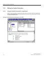
6
Editing Projects with
Different Versions of STEP 7
7
Defining Symbols
8
Creating Blocks and
Libraries
9
Basics of Creating Logic
Blocks
10
Creating Data Blocks
11
Parameter Assignment for
Data Blocks
12
Creating STL Source Files
13
Displaying Reference Data
14
Checking Block Consistency
and Time Stamps as a Block
Property
Continued an next page
15
Siemens AG
Industry Sector
Postfach 48 48
90026 NÜRNBERG
GERMANY
A5E02789666-01
Ⓟ 05/2010
Copyright © Siemens AG 2010.
Technical data subject to change
Continued
SIMATIC
Programming with STEP 7
Manual
Setting Up and Editing the
Project
16
Controlling and Monitoring
Variables
17
Establishing an Online
Connection and Making CPU
Settings
18
Downloading and Uploading
19
Testing with the Variable
Table
20
Testing Using Program
Status
21
Testing using the Simulation
Program (Optional Package)
22
Diagnostics
23
Printing and Archiving
24
Working with M7
Programmable Control
Systems
This manual is part of the documentation package
with the order number:
6ES7810-4CA10-8BW0
05/2010
A5E02789666-01
25
Tips and Tricks
26
Appendix
27
Legal information
Warning notice system
This manual contains notices you have to observe in order to ensure your personal safety, as well as to prevent
damage to property. The notices referring to your personal safety are highlighted in the manual by a safety alert
symbol, notices referring only to property damage have no safety alert symbol. These notices shown below are
graded according to the degree of danger.
DANGER
indicates that death or severe personal injury will result if proper precautions are not taken.
WARNING
indicates that death or severe personal injury may result if proper precautions are not taken.
CAUTION
with a safety alert symbol, indicates that minor personal injury can result if proper precautions are not taken.
CAUTION
without a safety alert symbol, indicates that property damage can result if proper precautions are not taken.
NOTICE
indicates that an unintended result or situation can occur if the corresponding information is not taken into
account.
If more than one degree of danger is present, the warning notice representing the highest degree of danger will
be used. A notice warning of injury to persons with a safety alert symbol may also include a warning relating to
property damage.
Qualified Personnel
The product/system described in this documentation may be operated only by personnel qualified for the specific
task in accordance with the relevant documentation for the specific task, in particular its warning notices and
safety instructions. Qualified personnel are those who, based on their training and experience, are capable of
identifying risks and avoiding potential hazards when working with these products/systems.
Proper use of Siemens products
Note the following:
WARNING
Siemens products may only be used for the applications described in the catalog and in the relevant technical
documentation. If products and components from other manufacturers are used, these must be recommended
or approved by Siemens. Proper transport, storage, installation, assembly, commissioning, operation and
maintenance are required to ensure that the products operate safely and without any problems. The permissible
ambient conditions must be adhered to. The information in the relevant documentation must be observed.
Trademarks
All names identified by ® are registered trademarks of the Siemens AG. The remaining trademarks in this
publication may be trademarks whose use by third parties for their own purposes could violate the rights of the
owner.
Disclaimer of Liability
We have reviewed the contents of this publication to ensure consistency with the hardware and software
described. Since variance cannot be precluded entirely, we cannot guarantee full consistency. However, the
information in this publication is reviewed regularly and any necessary corrections are included in subsequent
editions.
Siemens AG
Industry Sector
Postfach 48 48
90026 NÜRNBERG
GERMANY
A5E02789666-01
Ⓟ 02/2010
Copyright © Siemens AG 2010.
Technical data subject to change
Preface
Purpose
This manual provides a complete overview of programming with STEP 7. It is designed to support
you when installing and commissioning the software. It explains how to proceed when creating
programs and describes the components of user programs.
The manual is intended for people who are involved in carrying out control tasks using STEP 7 and
SIMATIC S7 automation systems.
We recommend that you familiarize yourself with the examples in the manual "Working with
STEP 7 V5.5, Getting Started." These examples provide an easy introduction to the topic
"Programming with STEP 7".
Basic Knowledge Required
In order to understand this manual, general knowledge of automation technology is required.
In addition, you must be familiar with using computers or PC-similar tools (for example,
programming devices) with the MS Windows XP, MS Windows Server 2003 or MS Windows 7
operating system.
Scope of the Manual
This manual is valid for release 5.5 of the STEP 7 programming software package.
You can find the latest information on the service packs:
•
in the "readme.rtf" file
•
in the updated STEP 7 online help.
The topic "What's new?" in the online help offers an excellent introduction and overview of the
newest STEP 7 innovations.
Programming with STEP 7
Manual, 05/2010, A5E02789666-01
5
Preface
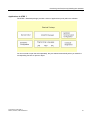
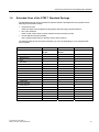
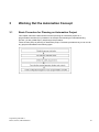
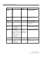
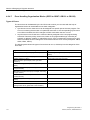
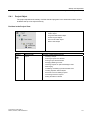
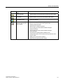
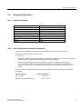
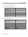
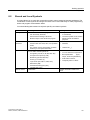
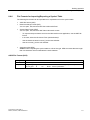
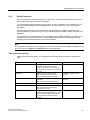
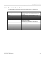
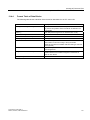
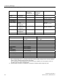
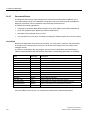
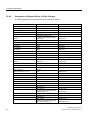
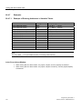
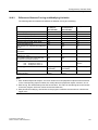
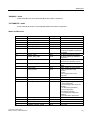
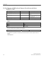
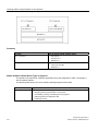
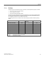
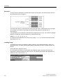
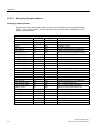
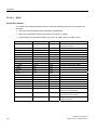
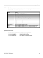
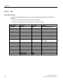
STEP 7 Documentation Packages
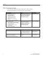
This manual is part of the documentation package "STEP 7 Basic Information“.
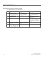
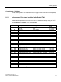
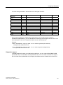
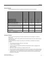
The following table displays an overview of the STEP 7 documentation:
Documentation
Purpose
STEP 7 Basic Information with
Basic information for technical
6ES7810-4CA10-8BW0
personnel describing the methods of
implementing control tasks with
STEP 7 and the S7-300/400
programmable controllers.
•
Working with STEP 7,
Getting Started Manual
•
Programming with STEP 7
•
Configuring Hardware and
Communication Connections,
STEP 7
•
From S5 to S7, Converter Manual
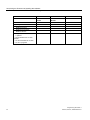
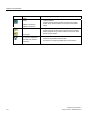
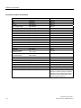
STEP 7 Reference with
6
Order Number
Provides reference information and
describes the programming
languages LAD, FBD and STL, and
standard and system function
extending the scope of the
STEP 7 basic information.
6ES7810-4CA10-8BW1
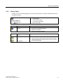
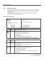
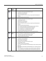
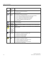
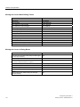
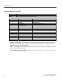
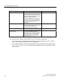
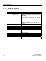
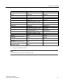
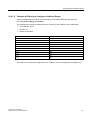
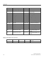
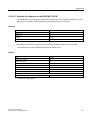
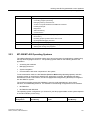
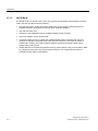
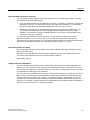
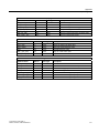
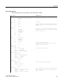
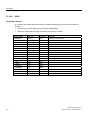
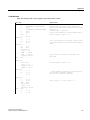
Online Helps
Purpose
Order Number
Help on STEP 7
Basic information on programming
and configuring hardware with
STEP 7 in the form of an online
help.
Part of the STEP 7
Standard software.
Reference helps on AWL/KOP/FUP
Reference help on SFBs/SFCs
Reference help on Organization Blocks
Context-sensitive reference
information.
Part of the STEP 7
Standard software.
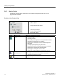
•
Ladder Logic (LAD) / Function Block
Diagram (FDB) / Statement List (STL) for
S7-300/400 manuals
•
Standard and System Function
for S7-300/400
Volume 1 and Volume 2
Programming with STEP 7
Manual, 05/2010, A5E02789666-01
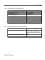
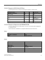
Preface
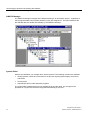
Online Help
The manual is complemented by an online help which is integrated in the software.
This online help is intended to provide you with detailed support when using the software.
The help system is integrated in the software via a number of interfaces:
•
There are several menu commands which you can select in the Help menu:
The Contents command opens the index for the Help on STEP 7.
•
Using Help provides detailed instructions on using the online help.
•
The context-sensitive help offers information on the current context, for example, an open
dialog box or an active window. You can open the contextsensitive help by clicking the "Help"
button or by pressing F1.
•
The status bar offers another form of context-sensitive help. It displays a short explanation for
each menu command when the mouse pointer is positioned on the menu command.
•
A brief explanation is also displayed for each icon in the toolbar when the mouse pointer is
positioned on the icon for a short time.
If you prefer to read the information from the online help in printed format, you can print out
individual help topics, books, or the entire online help.
This manual, as well as the manuals "Configuring Hardware and Communication Connections
STEP 7", "Modifiying the System During Operation via CiR" and "Automation System S7-400H Fault-Tolerant Systems" is an extract from the HTML-based Help on STEP 7. For detailed
procedures please refer to the STEP 7 help. As the manuals and the online help share an almost
identical structure, it is easy to switch between the manuals and the online help.
You can find the electronic manuals after installing STEP 7 via the Windows Start menu: Start >
SIMATIC > Documentation.
Programming with STEP 7
Manual, 05/2010, A5E02789666-01
7
Preface
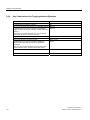
Further Support
If you have any technical questions, please get in touch with your Siemens representative or
responsible agent.
You will find your contact person at:
http://www.siemens.com/automation/partner
You will find a guide to the technical documentation offered for the individual SIMATIC Products
and Systems at:
http://www.siemens.com/simatic-tech-doku-portal
The online catalog and order system is found under:
http://mall.automation.siemens.com/
Training Centers
Siemens offers a number of training courses to familiarize you with the SIMATIC S7 automation
system. Please contact your regional training center or our central training center in D 90026
Nuremberg, Germany for details:
Internet: http://www.sitrain.com
8
Programming with STEP 7
Manual, 05/2010, A5E02789666-01
Preface
Technical Support
You can reach the Technical Support for all Industry Automation and Drive Technology products
•
Via the Web formula for the Support Request
http://www.siemens.com/automation/support-request
Additional information about our Technical Support can be found on the Internet pages
http://www.siemens.com/automation/service
Service & Support on the Internet
In addition to our documentation, we offer our Know-how online on the internet at:
http://www.siemens.com/automation/service&support
where you will find the following:
•
The newsletter, which constantly provides you with up-to-date information on your products.
•
The right documents via our Search function in Service & Support.
•
A forum, where users and experts from all over the world exchange their experiences.
•
Your local representative for Industry Automation and Drive Technology.
•
Information on field service, repairs, spare parts and consulting.
Programming with STEP 7
Manual, 05/2010, A5E02789666-01
9
Preface
10
Programming with STEP 7
Manual, 05/2010, A5E02789666-01
Contents
1
Introducing the Product and Installing the Software.............................................................................23
1.1
1.2
1.3
1.4
1.4.1
1.4.2
1.4.3
2
Installation..................................................................................................................................................43
2.1
2.1.1
2.1.2
2.1.3
2.2
2.2.1
2.2.2
2.3
2.4
2.4.1
2.4.2
3
Automation License Manager .................................................................................................43
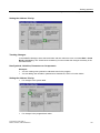
User Rights Through The Automation License Manager .......................................................43
Installing the Automation License Manager............................................................................46
Guidelines for Handling License Keys ....................................................................................47
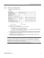
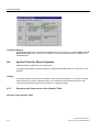
Installing STEP 7 ....................................................................................................................48
Installation Procedure .............................................................................................................50
Setting the PG/PC Interface ...................................................................................................53
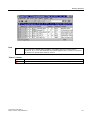
Uninstalling STEP 7 ................................................................................................................55
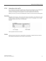
User Rights .............................................................................................................................55
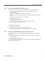
User Rights in MS Windows XP/Server 2003.........................................................................55
User Rights in MS Windows 7 ................................................................................................56
Working Out the Automation Concept....................................................................................................59
3.1
3.2
3.3
3.4
3.5
3.6
3.7
3.8
3.9
4
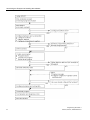
Overview of STEP 7................................................................................................................23
The STEP 7 Standard Package..............................................................................................28
What's New in STEP 7, Version 5.5? .....................................................................................33
Extended Uses of the STEP 7 Standard Package .................................................................35
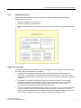
Engineering Tools ...................................................................................................................37
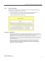
Run-Time Software .................................................................................................................39
Human Machine Interface.......................................................................................................41
Basic Procedure for Planning an Automation Project.............................................................59
Dividing the Process into Tasks and Areas ............................................................................60
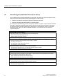
Describing the Individual Functional Areas ............................................................................62
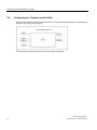
Listing Inputs, Outputs, and In/Outs .......................................................................................64
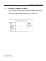
Creating an I/O Diagram for the Motors..................................................................................65
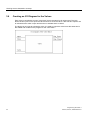
Creating an I/O Diagram for the Valves..................................................................................66
Establishing the Safety Requirements....................................................................................67
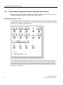
Describing the Required Operator Displays and Controls......................................................68
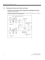
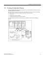
Creating a Configuration Diagram ..........................................................................................69
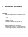
Basics of Designing a Program Structure ..............................................................................................71
4.1
4.2
4.2.1
4.2.2
4.2.3
4.2.3.1
4.2.3.2
4.2.3.3
4.2.3.4
4.2.3.5
4.2.3.6
Programs in a CPU .................................................................................................................71
Blocks in the User Program ....................................................................................................72
Organization Blocks and Program Structure ..........................................................................73
Call Hierarchy in the User Program ........................................................................................80
Block Types ............................................................................................................................82
Organization Block for Cyclic Program Processing (OB1) .....................................................82
Functions (FC) ........................................................................................................................88
Function Blocks (FB)...............................................................................................................90
Instance Data Blocks ..............................................................................................................93
Shared Data Blocks (DB)........................................................................................................96
System Function Blocks (SFB) and System Functions (SFC) ...............................................97
Programming with STEP 7
Manual, 05/2010, A5E02789666-01
11
Contents
4.2.4
4.2.4.1
4.2.4.2
4.2.4.3
4.2.4.4
4.2.4.5
4.2.4.6
4.2.4.7
5
Startup and Operation.............................................................................................................................113
5.1
5.2
5.3
5.4
5.4.1
5.4.2
5.4.3
5.4.4
5.4.5
5.4.6
5.4.7
5.4.8
5.5
5.5.1
5.5.2
5.5.3
5.5.4
5.5.5
5.5.6
5.5.7
5.5.8
5.6
5.6.1
5.6.2
5.6.3
5.6.4
5.6.5
5.6.6
6
Starting STEP 7 ....................................................................................................................113
Starting STEP 7 with Default Start Parameters ....................................................................114
Calling the Help Functions ....................................................................................................117
Objects and Object Hierarchy ...............................................................................................118
Project Object........................................................................................................................119
Library Object........................................................................................................................121
Station Object........................................................................................................................122
Programmable Module Object ..............................................................................................124
S7/M7 Program Object .........................................................................................................126
Block Folder Object...............................................................................................................128
Source File Folder Object .....................................................................................................131
S7/M7 Program without a Station or CPU ............................................................................132
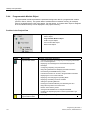
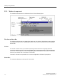
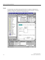
User Interface and Operation................................................................................................133
Operating Philosophy............................................................................................................133
Window Arrangement ...........................................................................................................134
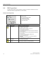
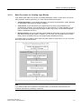
Elements in Dialog Boxes .....................................................................................................135
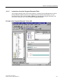
Creating and Managing Objects ...........................................................................................136
Selecting Objects in a Dialog Box.........................................................................................142
Session Memory ...................................................................................................................143
Changing the Window Arrangement.....................................................................................143
Saving and Restoring the Window Arrangement..................................................................144
Keyboard Operation..............................................................................................................145
Keyboard Control ..................................................................................................................145
Key Combinations for Menu Commands ..............................................................................145
Key Combinations for Moving the Cursor .............................................................................147
Key Combinations for Selecting Text....................................................................................149
Key Combinations for Access to Online Help .......................................................................149
Key Combinations for Toggling between Windows ..............................................................150
Setting Up and Editing the Project ........................................................................................................153
6.1
6.2
6.3
6.4
6.5
6.6
6.6.1
6.6.2
6.6.3
6.7
6.7.1
6.7.2
6.7.2.1
6.7.2.2
12
Organization Blocks for Interrupt-Driven Program Processing...............................................99
Time-of-Day Interrupt Organization Blocks (OB10 to OB17)................................................100
Time-Delay Interrupt Organization Blocks (OB20 to OB23) .................................................102
Cyclic Interrupt Organization Blocks (OB30 to OB38) ..........................................................103
Hardware Interrupt Organization Blocks (OB40 to OB47)....................................................105
Startup Organization Blocks (OB100 / OB101 / OB102) ......................................................106
Background Organization Block (OB90)...............................................................................108
Error Handling Organization Blocks (OB70 to OB87 / OB121 to OB122) ............................110
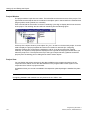
Project Structure ...................................................................................................................153
What You Should Know About Access Protection................................................................155
What You Should Know About The Change Log..................................................................158
Using Foreign-Language Character Sets .............................................................................159
Setting the MS Windows Language......................................................................................162
Setting Up a Project ..............................................................................................................163
Creating a Project .................................................................................................................163
Inserting Stations ..................................................................................................................165
Inserting an S7/M7 Program .................................................................................................166
Editing a Project....................................................................................................................168
Checking Projects for Software Packages Used ..................................................................169
Managing Multilingual Texts .................................................................................................169
Types of Multilingual Texts ...................................................................................................172
Structure of the Export File ...................................................................................................173
Programming with STEP 7
Manual, 05/2010, A5E02789666-01
Contents
6.7.2.3
6.7.2.4
6.7.2.5
6.7.2.6
6.7.2.7
6.7.3
6.7.3.1
6.7.3.2
6.7.3.3
6.7.3.4
7
Editing Projects with Different Versions of STEP 7.............................................................................185
7.1
7.2
7.3
7.4
7.5
8
Editing Version 2 Projects and Libraries...............................................................................185
Expanding DP Slaves That Were Created with Previous Versions of STEP 7 ....................185
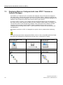
Editing Current Configurations with Previous Versions of STEP 7 ......................................187
Appending SIMATIC PC Configurations of Previous Versions ............................................188
Displaying Modules Configured with Later STEP 7 Versions or Optional Packages ...........190
Defining Symbols ....................................................................................................................................193
8.1
8.2
8.3
8.4
8.5
8.5.1
8.5.2
8.5.3
8.6
8.6.1
8.6.2
8.6.3
8.6.4
8.6.5
8.6.6
8.6.7
9
Information on the Log File ...................................................................................................175
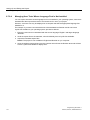
Managing User Texts Whose Language Font is Not Installed .............................................176
Optimizing the Source for Translation ..................................................................................177
Optimizing the Translation Process ......................................................................................178
Hiding Texts in Selected Languages ....................................................................................179
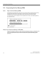
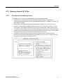
Micro Memory Card (MMC) as a Data Carrier......................................................................180
What You Should Know About Micro Memory Cards (MMC)...............................................180
Using a Micro Memory Card as a Data Carrier ....................................................................182
Memory Card File .................................................................................................................182
Storing Project Data on a Micro Memory Card (MMC).........................................................183
Absolute and Symbolic Addressing ......................................................................................193
Shared and Local Symbols...................................................................................................195
Displaying Shared or Local Symbols ....................................................................................196
Setting the Address Priority (Symbolic/Absolute) .................................................................197
Symbol Table for Shared Symbols .......................................................................................200
Structure and Components of the Symbol Table..................................................................200
Addresses and Data Types Permitted in the Symbol Table .................................................203
Incomplete and Non-Unique Symbols in the Symbol Table .................................................204
Entering Shared Symbols .....................................................................................................205
General Tips on Entering Symbols .......................................................................................205
Entering Single Shared Symbols in a Dialog Box.................................................................206
Entering Multiple Shared Symbols in the Symbol Table.......................................................207
Using Upper and Lower Case for Symbols ..........................................................................208
Exporting and Importing Symbol Tables...............................................................................210
File Formats for Importing/Exporting a Symbol Table ..........................................................211
Editing Areas in Symbol Tables............................................................................................214
Creating Blocks and Libraries ...............................................................................................................215
9.1
9.2
9.2.1
9.2.2
9.2.3
9.2.4
9.2.5
9.2.6
9.2.7
9.3
9.3.1
9.3.2
9.3.3
9.3.4
9.3.5
9.3.6
9.3.7
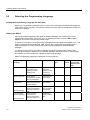
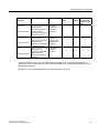
Selecting an Editing Method .................................................................................................215
Selecting the Programming Language .................................................................................216
Ladder Logic Programming Language (LAD).......................................................................218
Function Block Diagram Programming Language (FBD) .....................................................219
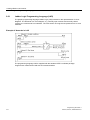
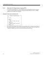
Statement List Programming Language (STL) .....................................................................220
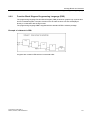
S7 SCL Programming Language..........................................................................................221
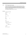
S7-GRAPH Programming Language (Sequential Control)...................................................222
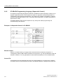
S7 HiGraph Programming Language (State Graph) ............................................................223
S7 CFC Programming Language .........................................................................................224
Creating Blocks.....................................................................................................................225
Blocks Folder ........................................................................................................................225
User-Defined Data Types (UDT) ..........................................................................................226
Block Properties....................................................................................................................227
Displaying Block Lengths......................................................................................................230
Comparing Blocks.................................................................................................................231
Rewiring ................................................................................................................................234
Attributes for Blocks and Parameters ...................................................................................234
Programming with STEP 7
Manual, 05/2010, A5E02789666-01
13
Contents
9.4
9.4.1
9.4.2
10
Basics of Creating Logic Blocks ...........................................................................................................239
10.1.1
10.1.2
10.1.3
10.1.4
10.1.5
10.2
10.2.1
10.2.2
10.2.3
10.3
10.3.1
10.3.2
10.3.3
10.4
10.4.1
10.4.2
10.4.3
10.4.4
10.4.5
10.4.6
10.4.7
10.5
10.5.1
10.5.2
10.5.3
10.6
10.6.1
10.6.2
10.7
10.7.1
10.7.2
10.8
10.8.1
10.9
14
Working with Libraries...........................................................................................................235
Hierarchical Structure of Libraries.........................................................................................237
Overview of the Standard Libraries.......................................................................................237
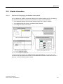
Structure of the Program Editor Window ..............................................................................239
Basic Procedure for Creating Logic Blocks ..........................................................................241
Default Settings for the LAD/STL/FBD Program Editor ........................................................242
Access Rights to Blocks and Source Files ...........................................................................242
Instructions from the Program Elements Table ....................................................................243
Editing the Variable Declaration............................................................................................244
Using the Variable Declaration in Logic Blocks ....................................................................244
Interaction Between The Variable Detail View And The Instruction List ..............................245
Structure of the Variable Declaration Window ......................................................................246
Multiple Instances in the Variable Declaration......................................................................247
Using Multiple Instances .......................................................................................................247
Rules for Declaring Multiple Instances .................................................................................248
Entering a Multiple Instance in the Variable Declaration Window ........................................248
General Notes on Entering Statements and Comments ......................................................249
Structure of the Code Section...............................................................................................249
Procedure for Entering Statements ......................................................................................250
Entering Shared Symbols in a Program ...............................................................................251
Title and Comments for Blocks and Networks......................................................................251
Entering Block Comments and Network Comments.............................................................253
Working with Network Templates .........................................................................................253
Search Function for Errors in the Code Section ...................................................................254
Editing LAD Elements in the Code Section ..........................................................................255
Settings for Ladder Logic Programming ...............................................................................255
Rules for Entering Ladder Logic Elements ...........................................................................256
Illegal Logic Operations in Ladder ........................................................................................258
Editing FBD Elements in the Code Section ..........................................................................259
Settings for Function Block Diagram Programming..............................................................259
Rules for Entering FBD Elements .........................................................................................260
Editing STL Statements in the Code Section........................................................................262
Settings for Statement List Programming .............................................................................262
Rules for Entering STL Statements ......................................................................................262
Updating Block Calls.............................................................................................................263
Changing Interfaces..............................................................................................................264
Saving Logic Blocks..............................................................................................................265
Programming with STEP 7
Manual, 05/2010, A5E02789666-01
Contents
11
Creating Data Blocks ..............................................................................................................................267
11.1
11.2
11.3
11.4
11.4.1
11.4.2
11.4.3
11.4.4
11.4.5
11.4.6
11.4.7
12
Parameter Assignment for Data Blocks................................................................................................277
12.1
13
Basic Information on Creating Data Blocks ..........................................................................267
Declaration View of Data Blocks...........................................................................................268
Data View of Data Blocks .....................................................................................................269
Editing and Saving Data Blocks............................................................................................270
Entering the Data Structure of Shared Data Blocks .............................................................270
Entering and Displaying the Data Structure of Data Blocks Referencing an FB (Instance
DBs) ......................................................................................................................................271
Entering the Data Structure of User-Defined Data Types (UDT) .........................................273
Entering and Displaying the Structure of Data Blocks Referencing a UDT..........................274
Editing Data Values in the Data View ...................................................................................275
Resetting Data Values to their Initial Values ........................................................................275
Saving Data Blocks...............................................................................................................276
Assigning Parameters to Technological Functions...............................................................278
Creating STL Source Files......................................................................................................................279
13.1
13.2
13.2.1
13.2.2
13.2.3
13.2.4
13.2.5
13.2.6
13.3
13.3.1
13.3.2
13.3.3
13.4
13.4.1
13.4.2
13.4.3
13.4.4
13.5
13.5.1
13.5.2
13.5.3
13.5.4
13.5.5
13.5.6
13.5.7
13.5.8
13.5.9
13.5.10
13.6
13.6.1
13.6.2
13.6.3
13.6.4
13.7
13.7.1
Basic Information on Programming in STL Source Files......................................................279
Rules for Programming in STL Source Files ........................................................................280
Rules for Entering Statements in STL Source Files .............................................................280
Rules for Declaring Variables in STL Source Files...............................................................281
Rules for Block Order in STL Source Files ...........................................................................282
Rules for Setting System Attributes in STL Source Files .....................................................282
Rules for Setting Block Properties in STL Source Files .......................................................283
Permitted Block Properties for Each Block Type..................................................................285
Structure of Blocks in STL Source Files ...............................................................................286
Structure of Logic Blocks in STL Source Files .....................................................................286
Structure of Data Blocks in STL Source Files ......................................................................287
Structure of User-Defined Data Types in STL Source Files .................................................287
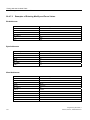
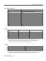
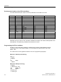
Syntax and Formats for Blocks in STL Source Files ............................................................288
Format Table of Organization Blocks ...................................................................................288
Format Table of Function Blocks ..........................................................................................289
Format Table of Functions....................................................................................................290
Format Table of Data Blocks ................................................................................................291
Creating STL Source Files....................................................................................................292
Creating STL Source Files....................................................................................................292
Editing S7 Source Files ........................................................................................................292
Setting The Layout of Source Code Text..............................................................................293
Inserting Block Templates in STL Source Files....................................................................293
Inserting the Contents of Other STL Source Files................................................................293
Inserting Source Code from Existing Blocks in STL Source Files........................................294
Inserting External Source Files.............................................................................................294
Generating STL Source Files from Blocks............................................................................295
Importing Source Files ..........................................................................................................295
Exporting Source Files..........................................................................................................295
Saving and Compiling STL Source Files and Executing a Consistency Check ...................296
Saving STL Source Files ......................................................................................................296
Checking Consistency in STL Source Files..........................................................................296
Debugging STL Source Files................................................................................................296
Compiling STL Source Files .................................................................................................297
Examples of STL Source Files .............................................................................................298
Examples of Declaring Variables in STL Source Files .........................................................298
Programming with STEP 7
Manual, 05/2010, A5E02789666-01
15
Contents
13.7.2
13.7.3
13.7.4
13.7.5
13.7.6
14
Displaying Reference Data .....................................................................................................................309
14.1
14.1.1
14.1.2
14.1.3
14.1.4
14.1.5
14.1.6
14.2
14.2.1
14.2.2
14.2.3
14.2.4
14.2.5
15
Checking Block Consistency.................................................................................................325
Time Stamps as a Block Property and Time Stamp Conflicts ..............................................327
Time Stamps in Logic Blocks................................................................................................328
Time Stamps in Shared Data Blocks ....................................................................................329
Time Stamps in Instance Data Blocks ..................................................................................329
Time Stamps in UDTs and Data Blocks Derived from UDTs ...............................................330
Correcting the Interfaces in a Function, Function Block, or UDT .........................................330
Avoiding Errors when Calling Blocks ....................................................................................331
Configuring Messages ............................................................................................................................333
16.1
16.1.1
16.1.2
16.1.3
16.1.4
16.1.5
16.1.6
16.1.7
16.1.8
16.1.9
16.1.10
16.1.11
16.2
16.2.1
16.2.2
16.2.2.1
16.2.2.2
16.2.2.3
16.2.3
16.2.3.1
16.2.4
16
Overview of the Available Reference Data ...........................................................................309
Cross-Reference List ............................................................................................................311
Program Structure.................................................................................................................312
Assignment List.....................................................................................................................314
Unused Symbols...................................................................................................................316
Addresses Without Symbols .................................................................................................317
Displaying Block Information for LAD, FBD, and STL ..........................................................317
Working with Reference Data ...............................................................................................318
Ways of Displaying Reference Data .....................................................................................318
Displaying Lists in Additional Working Windows ..................................................................318
Generating and Displaying Reference Data .........................................................................319
Finding Address Locations in the Program Quickly ..............................................................320
Example of Working with Address Locations........................................................................321
Checking Block Consistency and Time Stamps as a Block Property ...............................................325
15.1
15.2
15.3
15.4
15.5
15.6
15.7
15.8
16
Example of Organization Blocks in STL Source Files ..........................................................299
Example of Functions in STL Source Files...........................................................................301
Example of Function Blocks in STL Source Files .................................................................304
Example of Data Blocks in STL Source Files .......................................................................307
Example of User-Defined Data Types in STL Source Files..................................................308
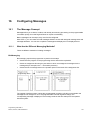
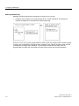
The Message Concept..........................................................................................................333
What Are the Different Messaging Methods? .......................................................................333
Choosing a Messaging Method ............................................................................................335
SIMATIC Components ..........................................................................................................337
Parts of a Message ...............................................................................................................338
Which Message Blocks Are Available? ................................................................................339
Formal Parameters, System Attributes, and Message Blocks .............................................341
Message Type and Messages ..............................................................................................342
How to Generate an STL Source File from Message-Type Blocks ......................................344
Assigning Message Numbers ...............................................................................................344
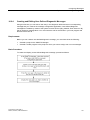
Differences Between Project-Oriented and CPU-Oriented Assignment
of Message Numbers............................................................................................................345
Options for Modifying the Message Number Assignment of a Project .................................346
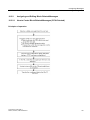
Project-Oriented Message Configuration..............................................................................347
How to Assign Project-Oriented Message Numbers ............................................................347
Assigning and Editing Block-Related Messages ..................................................................347
How to Create Block-Related Messages (Project-Oriented) ................................................348
How to Edit Block-Related Messages (Project-Oriented).....................................................350
How to Configure PCS 7 Messages (Project-Oriented) .......................................................351
Assigning and Editing Symbol-Related Messages ...............................................................352
How to Assign and Edit Symbol-Related Messages (Project-Oriented)...............................352
Creating and Editing User-Defined Diagnostic Messages....................................................353
Programming with STEP 7
Manual, 05/2010, A5E02789666-01
Contents
16.3
16.3.1
16.3.2
16.3.2.1
16.3.2.2
16.3.2.3
16.3.3
16.3.3.1
16.3.4
16.4
16.4.1
16.4.2
16.4.3
16.5
16.5.1
16.6
16.6.1
16.6.2
16.6.3
16.6.4
16.6.5
16.7
16.7.1
16.8
16.8.1
16.8.2
16.9
16.9.1
16.9.2
16.9.3
16.9.4
16.9.5
16.9.6
16.9.7
16.9.8
16.9.9
17
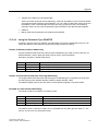
CPU-Oriented Message Configuration .................................................................................354
How to Assign CPU-Oriented Message Numbers................................................................354
Assigning and Editing Block-Related Messages ..................................................................355
How to Create Block-Related Messages (CPU-Oriented)....................................................355
How to Edit Block-Related Messages (CPU-Oriented) ........................................................358
How to Configure PCS 7 Messages (CPU-Oriented) ...........................................................358
Assigning and Editing Symbol-Related Messages ...............................................................360
How to Assign and Edit Symbol-Related Messages (CPU-Oriented) ..................................360
Creating and Editing User-Defined Diagnostic Messages ...................................................361
Tips for Editing Messages ....................................................................................................362
Adding Associated Values to Messages ..............................................................................362
Integrating Texts from Text Libraries into Messages............................................................365
Deleting Associated Values ..................................................................................................365
Translating and Editing Operator Related Texts ..................................................................366
Translating and Editing User Texts.......................................................................................366
Translating and Editing Text Libraries ..................................................................................368
User Text Libraries................................................................................................................368
Creating User Text Libraries.................................................................................................368
How to Edit User Text Libraries ............................................................................................369
System Text Libraries ...........................................................................................................369
Translating Text Libraries .....................................................................................................370
Transferring Message Configuration Data to the Programmable Controller ........................372
Transferring Configuration Data to the Programmable Controller........................................372
Displaying CPU Messages and User-Defined Diagnostic Messages ..................................373
Configuring CPU Messages .................................................................................................376
Displaying Stored CPU Messages........................................................................................376
Configuring the 'Reporting of System Errors' .......................................................................377
Overview of 'Report System Error'........................................................................................377
Configuring the 'Reporting of System Errors' .......................................................................377
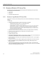
Supported Components and Functional Scope....................................................................379
Settings for "Report System Error" .......................................................................................383
Generating Blocks for Reporting System Errors...................................................................385
Generated Error OBs ............................................................................................................386
Generated Blocks .................................................................................................................388
Assignment of System Errors to Error Classes ....................................................................390
Generating Foreign-Language Message Texts in 'Report System Error'.............................392
Controlling and Monitoring Variables ...................................................................................................395
17.1
17.2
17.3
17.4
17.5
Configuring Variables for Operator Control and Monitoring .................................................395
Configuring Operator Control and Monitoring Attributes with Statement List,
Ladder Logic, and Function Block Diagram..........................................................................397
Configuring Operator Control and Monitoring Attributes via the Symbol Table ...................398
Changing Operator Control and Monitoring Attributes with CFC .........................................399
Transferring Configuration Data to the Operator Interface Programmable Controller .........400
Programming with STEP 7
Manual, 05/2010, A5E02789666-01
17
Contents
18
Establishing an Online Connection and Making CPU Settings ..........................................................401
18.1
18.1.1
18.1.2
18.1.3
18.1.4
18.1.5
18.2
18.3
18.3.1
18.4
18.4.1
19
Downloading and Uploading ..................................................................................................................415
19.1
19.1.1
19.1.2
19.1.3
19.1.4
19.1.5
19.1.6
19.1.6.1
19.1.6.2
19.1.6.3
19.1.6.4
19.1.6.5
19.2
19.2.1
19.2.2
19.3
19.3.1
19.3.2
19.3.3
19.3.3.1
19.3.3.2
19.4
19.4.1
19.4.2
19.5
19.5.1
19.5.2
20
Downloading from the PG/PC to the Programmable Controller ...........................................415
Requirements for Downloading.............................................................................................415
Differences Between Saving and Downloading Blocks ........................................................417
Load Memory and Work Memory in the CPU .......................................................................418
Download Methods Dependent on the Load Memory ..........................................................420
Updating Firmware in Modules and Submodules Online .....................................................421
Downloading a Program to the S7 CPU ...............................................................................424
Downloading with Project Management ...............................................................................424
Downloading without Project Management ..........................................................................424
Reloading Blocks in the Programmable Controller ...............................................................424
Saving Downloaded Blocks on Integrated EPROM..............................................................425
Downloading via EPROM Memory Cards.............................................................................426
Compiling and Downloading Several Objects from the PG ..................................................427
Requirements for and Notes on Downloading ......................................................................427
Compiling and Downloading Objects....................................................................................429
Uploading from the Programmable Controller to the PG/PC................................................431
Uploading a Station...............................................................................................................433
Uploading Blocks from an S7 CPU .......................................................................................434
Editing Uploaded Blocks in the PG/PC.................................................................................434
Editing Uploaded Blocks if the User Program is on the PG/PC............................................435
Editing Uploaded Blocks if the User Program is Not on the PG/PC .....................................435
Deleting on the Programmable Controller ............................................................................436
Erasing the Load/Work Memory and Resetting the CPU .....................................................436
Deleting S7 Blocks on the Programmable Controller ...........................................................437
Compressing the User Memory (RAM).................................................................................438
Gaps in the User Memory (RAM)..........................................................................................438
Compressing the Memory Contents of an S7 CPU ..............................................................439
Testing with the Variable Table..............................................................................................................441
20.1
20.2
20.3
20.3.1
20.3.1.1
20.3.2
20.3.3
20.4
20.4.1
20.4.2
18
Establishing Online Connections ..........................................................................................401
Establishing an Online Connection via the "Accessible Nodes" Window .............................401
Establishing an Online Connection via the Online Window of the Project ...........................402
Online Access to PLCs in a Multiproject...............................................................................403
Password Protection for Access to Programmable Controllers............................................405
Updating the Window Contents ............................................................................................407
Displaying and Changing the Operating Mode .....................................................................408
Displaying and Setting the Time and Date ...........................................................................409
CPU Clocks with Time Zone Setting and Summer/Winter Time ..........................................409
Updating the Firmware..........................................................................................................411
Updating Firmware in Modules and Submodules Online .....................................................411
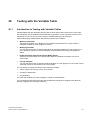
Introduction to Testing with Variable Tables.........................................................................441
Basic Procedure when Monitoring and Modifying with the Variable Table...........................442
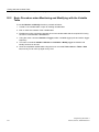
Editing and Saving Variable Tables......................................................................................443
Creating and Opening a Variable Table ...............................................................................443
How to Create and Open a Variable Table...........................................................................444
Copying/Moving Variable Tables ..........................................................................................445
Saving a Variable Table........................................................................................................445
Entering Variables in Variable Table ....................................................................................446
Inserting Addresses or Symbols in a Variable Table ............................................................446
Inserting a Contiguous Address Range in a Variable Table.................................................449
Programming with STEP 7
Manual, 05/2010, A5E02789666-01
Contents
20.4.3
20.4.4
20.4.5
20.4.6
20.4.7
20.4.7.1
20.4.7.2
20.4.7.3
20.5
20.6
20.6.1
20.6.2
20.7
20.7.1
20.7.2
20.8
20.8.1
20.8.2
20.8.3
21
Testing Using Program Status...............................................................................................................467
21.1
21.2
21.3
21.4
21.4.1
22
Program Status Display ........................................................................................................468
What You Should Know About Testing in Single-Step Mode/Breakpoints...........................470
What You Should Know About the HOLD Mode ..................................................................472
Program Status of Data Blocks.............................................................................................473
Setting the Display for Program Status.................................................................................474
Testing using the Simulation Program (Optional Package) ...............................................................475
22.1
23
Inserting Modify Values ........................................................................................................449
Upper Limits for Entering Timers ..........................................................................................450
Upper Limits for Entering Counters ......................................................................................451
Inserting Comment Lines......................................................................................................451
Examples ..............................................................................................................................452
Example of Entering Addresses in Variable Tables .............................................................452
Example of Entering a Contiguous Address Range .............................................................453
Examples of Entering Modify and Force Values...................................................................454
Establishing a Connection to the CPU..................................................................................456
Monitoring Variables .............................................................................................................457
Introduction to Monitoring Variables .....................................................................................457
Defining the Trigger for Monitoring Variables .......................................................................457
Modifying Variables...............................................................................................................459
Introduction to Modifying Variables.......................................................................................459
Defining the Trigger for Modifying Variables ........................................................................460
Forcing Variables ..................................................................................................................462
Safety Measures When Forcing Variables ...........................................................................462
Introduction to Forcing Variables ..........................................................................................463
Differences Between Forcing and Modifying Variables ........................................................465
Testing using the Simulation Program S7 PLCSIM (Optional Package)..............................475
Diagnostics ..............................................................................................................................................477
23.1
23.2
23.3
23.3.1
23.3.2
23.4
23.4.1
23.4.2
23.5
23.5.1
23.5.2
23.5.3
23.5.4
23.6
23.6.1
23.6.2
23.7
23.7.1
23.8
23.8.1
23.8.2
23.8.3
23.9
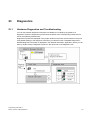
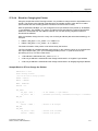
Hardware Diagnostics and Troubleshooting.........................................................................477
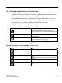
Diagnostics Symbols in the Online View ..............................................................................479
Diagnosing Hardware: Quick View .......................................................................................481
Calling the Quick View ..........................................................................................................481
Information Functions in the Quick View ..............................................................................481
Diagnosing Hardware: Diagnostic View ...............................................................................482
Calling the Diagnostic View ..................................................................................................482
Information Functions in the Diagnostic View.......................................................................484
Module Information ...............................................................................................................485
Options for Displaying the Module Information.....................................................................485
Module Information Functions ..............................................................................................486
Scope of the Module Type-Dependent Information..............................................................488
Displaying the Module Status of PA Field Devices and DP Slaves After a Y-Link...............490
Diagnosing in STOP Mode ...................................................................................................492
Basic Procedure for Determining the Cause of a STOP ......................................................492
Stack Contents in STOP Mode.............................................................................................493
Checking Scan Cycle Times to Avoid Time Errors...............................................................494
Checking Scan Cycle Times to Avoid Time Errors...............................................................494
Flow of Diagnostic Information .............................................................................................495
System Status List SSL ........................................................................................................496
Sending Your Own Diagnostic Messages ............................................................................499
Diagnostic Functions.............................................................................................................500
Program Measures for Handling Errors ................................................................................501
Programming with STEP 7
Manual, 05/2010, A5E02789666-01
19
Contents
23.9.1
23.9.2
23.9.3
23.9.4
23.9.5
23.9.6
23.9.7
23.9.8
23.9.9
23.9.10
23.9.11
23.9.12
23.9.13
23.9.14
23.9.15
23.10
23.10.1
23.10.2
23.10.2.1
23.10.2.2
23.10.2.3
23.10.2.4
23.10.2.5
23.10.2.6
Evaluating the Output Parameter RET_VAL ........................................................................502
Error OBs as a Reaction to Detected Errors.........................................................................503
Inserting Substitute Values for Error Detection.....................................................................508
I/O Redundancy Error (OB70) ..............................................................................................510
CPU Redundancy Error (OB72)............................................................................................511
Time Error (OB80) ................................................................................................................512
Power Supply Error (OB81) ..................................................................................................513
Diagnostic Interrupt (OB82) ..................................................................................................514
Insert/Remove Module Interrupt (OB83)...............................................................................515
CPU Hardware Fault (OB84) ................................................................................................516
Program Sequence Error (OB85) .........................................................................................516
Rack Failure (OB86) .............................................................................................................517
Communication Error (OB87) ...............................................................................................517
Programming Error (OB121).................................................................................................518
I/O Access Error (OB122) .....................................................................................................518
System Diagnostics with 'Report System Error'....................................................................519
Graphical Output of Diagnostic Events.................................................................................519
Diagnostic Status ..................................................................................................................519
Overview of the Diagnostic Status ........................................................................................519
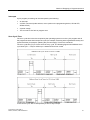
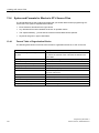
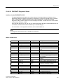
PROFIBUS Diagnostic Status...............................................................................................519
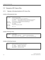
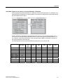
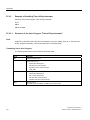
Example of a DB 125 with a DP Slave .................................................................................523
Example of a Request for the PROFIBUS DP DB................................................................523
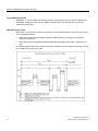
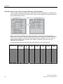
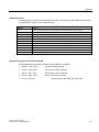
PROFINET Diagnostic Status...............................................................................................525
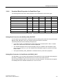
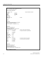
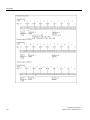
Example of a DB126 with an IO System 100 and Devices with Device Numbers 2, 3
and 4 .....................................................................................................................................528
23.10.2.7 Example of a Request for the PROFINET IO DB .................................................................529
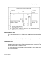
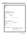
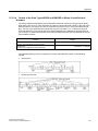
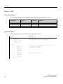
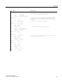
23.10.2.8 Diagnostic Status DB ............................................................................................................530
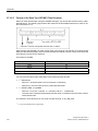
23.10.2.9 Example of a Diagnostic Status DB Query ...........................................................................533
23.10.2.10 Importing Error and Help Texts.............................................................................................536
24
Printing and Archiving ............................................................................................................................539
24.1
24.1.1
24.1.2
24.1.3
24.2
24.2.1
24.2.2
24.2.3
25
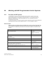
Working with M7 Programmable Control Systems ..............................................................................545
25.1
25.2
25.3
20
Printing Project Documentation ............................................................................................539
Basic Procedure when Printing.............................................................................................540
Print Functions ......................................................................................................................540
Special Note on Printing the Object Tree .............................................................................541
Archiving Projects and Libraries ...........................................................................................542
Uses for Saving/Archiving.....................................................................................................543
Requirements for Archiving...................................................................................................544
Procedure for Archiving/Retrieving .......................................................................................544
Procedure for M7 Systems ...................................................................................................545
Optional Software for M7 Programming ...............................................................................547
M7-300/M7-400 Operating Systems.....................................................................................549
Programming with STEP 7
Manual, 05/2010, A5E02789666-01
Contents
26
Tips and Tricks ........................................................................................................................................551
26.1
26.2
26.3
26.4
26.5
26.6
26.7
27
Exchanging Modules in the Configuration Table ..................................................................551
Projects with a Large Number of Networked Stations ..........................................................551
Rearranging ..........................................................................................................................552
Editing Symbols Across Multiple Networks ..........................................................................552
Testing with the Variable Table ............................................................................................553
Modifying Variables With the Program Editor.......................................................................554
Virtual Work Memory ............................................................................................................555
Appendix ..................................................................................................................................................557
27.1
27.1.1
27.1.2
27.1.3
27.1.4
27.1.5
27.2
27.2.1
27.2.2
27.2.3
27.2.3.1
27.2.3.2
27.2.3.3
27.2.3.4
27.2.3.5
27.2.3.6
27.2.3.7
27.2.3.8
27.2.3.9
27.2.3.10
27.3
27.3.1
27.3.2
27.3.2.1
27.3.2.2
27.3.2.3
27.3.2.4
27.3.2.5
27.3.3
27.3.3.1
27.3.3.2
27.3.3.3
27.3.3.4
27.3.3.5
27.3.3.6
Operating Modes ..................................................................................................................557
Operating Modes and Mode Transitions ..............................................................................557
STOP Mode ..........................................................................................................................560
STARTUP Mode ...................................................................................................................561
RUN Mode ............................................................................................................................569
HOLD Mode ..........................................................................................................................570
Memory Areas of S7 CPUs...................................................................................................571
Distribution of the Memory Areas .........................................................................................571
Load Memory and Work Memory .........................................................................................572
System Memory ....................................................................................................................574
Using the System Memory Areas .........................................................................................574
Process-Image Input/Output Tables .....................................................................................576
Local Data Stack...................................................................................................................580
Interrupt Stack.......................................................................................................................581
Block Stack ...........................................................................................................................582
Diagnostic Buffer...................................................................................................................583
Evaluating the Diagnostic Buffer...........................................................................................583
Retentive Memory Areas on S7-300 CPUs ..........................................................................585
Retentive Memory Areas on S7-400 CPUs ..........................................................................586
Configurable Memory Objects in the Work Memory.............................................................587
Data Types and Parameter Types........................................................................................588
Introduction to Data Types and Parameter Types................................................................588
Elementary Data Types ........................................................................................................589
Format of the Data Type INT (16-Bit Integers) .....................................................................590
Format of the Data Type DINT (32-Bit Integers) ..................................................................590
Format of the Data Type REAL (Floating-Point Numbers) ...................................................591
Format of the Data Types WORD and DWORD in Binary Coded Decimal Numbers..........595
Format of the Data Type S5TIME (Time Duration)...............................................................596
Complex Data Types ............................................................................................................597
Complex Data Types ............................................................................................................597
Format of the Data Type DATE_AND_TIME........................................................................598
Using Complex Data Types ..................................................................................................600
Using Arrays to Access Data ................................................................................................601
Using Structures to Access Data ..........................................................................................604
Using User-Defined Data Types to Access Data..................................................................606
Programming with STEP 7
Manual, 05/2010, A5E02789666-01
21
Contents
27.3.4
27.3.4.1
27.3.4.2
27.3.4.3
27.3.4.4
27.3.4.5
27.3.4.6
27.3.4.7
27.3.4.8
27.3.4.9
27.4
27.4.1
27.4.2
27.4.3
27.5
27.5.1
27.6
27.6.1
27.6.2
27.6.2.1
27.6.2.2
27.6.2.3
27.6.2.4
27.6.2.5
27.6.3
27.6.3.1
27.6.3.2
27.6.3.3
27.6.3.4
27.6.4
27.6.4.1
27.6.4.2
27.6.4.3
27.6.4.4
27.6.4.5
27.6.4.6
27.7
27.7.1
27.7.2
27.8
27.8.1
27.8.2
27.8.3
27.8.4
Parameter Types ..................................................................................................................609
Format of the Parameter Types BLOCK, COUNTER, TIMER .............................................610
Format of the Parameter Type POINTER.............................................................................610
Using the Parameter Type POINTER...................................................................................611
Block for Changing the Pointer .............................................................................................613
Format of the Parameter Type ANY .....................................................................................616
Using the Parameter Type ANY............................................................................................619
Assigning Data Types to Local Data of Logic Blocks ...........................................................622
Permitted Data Types when Transferring Parameters .........................................................624
Transferring to IN_OUT Parameters of a Function Block.....................................................629
Working with Older Projects..................................................................................................630
Converting Version 2 Projects ..............................................................................................630
Editing Version 2 Projects and Libraries...............................................................................631
Notes on STEP 7 V.2.1 Projects with GD Communication...................................................631
Expanding DP Slaves That Were Created with Previous Versions of STEP 7 ....................632
DP-Slaves with Missing or Faulty GSD Files........................................................................633
Sample Programs .................................................................................................................634
Sample Projects and Sample Programs...............................................................................634
Sample Program for an Industrial Blending Process ............................................................636
Defining Logic Blocks............................................................................................................639
Assigning Symbolic Names ..................................................................................................640
Creating the FB for the Motor ...............................................................................................642
Creating the FC for the Valves..............................................................................................646
Creating OB1 ........................................................................................................................648
Example of Handling Time-of-Day Interrupts........................................................................654
Structure of the User Program "Time-of-Day Interrupts" ......................................................654
FC12 .....................................................................................................................................656
OB10 .....................................................................................................................................658
OB1 and OB80......................................................................................................................660
Example of Handling Time-Delay Interrupts .........................................................................662
Structure of the User Program "Time-Delay Interrupts"........................................................662
OB20 .....................................................................................................................................664
OB1 .......................................................................................................................................666
Example of Masking and Unmasking Synchronous Errors ..................................................668
Example of Disabling and Enabling Interrupts and Asynchronous Errors
(SFC39 and SFC40) .............................................................................................................672
Example of the Delayed Processing of Interrupts and Asynchronous Errors
(SFC41 and SFC42) .............................................................................................................673
Accessing Process and I/O Data Areas................................................................................674
Accessing the Process Data Area ........................................................................................674
Accessing the Peripheral Data Area.....................................................................................676
Setting the Operating Behavior.............................................................................................678
Changing the Behavior and Properties of Modules ..............................................................679
Updating the Firmware (of the Operating System) in Modules and Submodules Offline .....681
Using the Clock Functions ....................................................................................................682
Using Clock Memory and Timers..........................................................................................683
Index ...................................................................................................................................................................685
22
Programming with STEP 7
Manual, 05/2010, A5E02789666-01
1
Introducing the Product and Installing the Software
1.1
Overview of STEP 7
What is STEP 7?
STEP 7 is the standard software package used for configuring and programming SIMATIC
programmable logic controllers. It is part of the SIMATIC industry software. There are the following
versions of the STEP 7 Standard package:
•
STEP 7 Micro/DOS and STEP 7 Micro/Win for simpler stand-alone applications on the
SIMATIC S7-200.
•
STEP 7 for applications on SIMATIC S7-300/S7-400, SIMATIC M7-300/M7-400, and
SIMATIC C7 with a wider range of functions:
-
Can be extended as an option by the software products in the SIMATIC Industry Software
(see also Extended Uses of the STEP 7 Standard Package)
-
Opportunity of assigning parameters to function modules and communications processors
-
Forcing and multicomputing mode
-
Global data communication
-
Event-driven data transfer using communication function blocks
-
Configuring connections
STEP 7 is the subject of this documentation, STEP 7 Micro is described in the "STEP 7
Micro/DOS" documentation.
Basic Tasks
When you create an automation solution with STEP 7, there are a series of basic tasks. The
following figure shows the tasks that need to be performed for most projects and assigns them to a
basic procedure. It refers you to the relevant chapter thus giving you the opportunity of moving
through the manual to find task-related information.
Programming with STEP 7
Manual, 05/2010, A5E02789666-01
23
Introducing the Product and Installing the Software
1.1 Overview of STEP 7
24
Programming with STEP 7
Manual, 05/2010, A5E02789666-01
Introducing the Product and Installing the Software
1.1 Overview of STEP 7
Alternative Procedures
As shown in the figure above, you have two alternative procedures:
•
You can configure the hardware first and then program the blocks.
•
You can, however, program the blocks first without configuring the hardware. This is
recommended for service and maintenance work, for example, to integrate programmed blocks
into in an existing project.
Brief Description of the Individual Steps
•
Install STEP 7 and license keys
The first time you use STEP 7, install it and transfer the license keys from diskette to the hard
disk (see also Installing STEP 7 and Authorization).
•
Plan your controller
Before you work with STEP 7, plan your automation solution from dividing the process into
individual tasks to creating a configuration diagram (see also Basic Procedure for Planning an
Automation Project).
•
Design the program structure
Turn the tasks described in the draft of your controller design into a program structure using the
blocks available in STEP 7 (see also Blocks in the User Program).
•
Start STEP 7
You start STEP 7 from the Windows user interface (see also Starting STEP 7).
•
Create a project structure
A project is like a folder in which all data are stored in a hierarchical structure and are available
to you at any time. After you have created a project, all other tasks are executed in this project
(see also Project Structure).
•
Configure a station
When you configure the station you specify the programmable controller you want to use; for
example, SIMATIC 300, SIMATIC 400, SIMATIC S5 (see also Inserting Stations).
•
Configure hardware
When you configure the hardware you specify in a configuration table which modules you want
to use for your automation solution and which addresses are to be used to access the modules
from the user program. The properties of the modules can also be assigned using parameters
(see also Basic Procedure for Configuring Hardware).
•
Configure networks and communication connections
The basis for communication is a pre-configured network. For this, you will need to create the
subnets required for your automation networks, set the subnet properties, and set the network
connection properties and any communication connections required for the networked stations
(see also Procedure for Configuring a Subnet).
•
Define symbols
You can define local or shared symbols, which have more descriptive names, in a symbol table
to use instead of absolute addresses in your user program (see also Creating a Symbol Table).
•
Create the program
Using one of the available programming languages create a program linked to a module or
independent of a module and store it as blocks, source files, or charts (see also Basic
Programming with STEP 7
Manual, 05/2010, A5E02789666-01
25
Introducing the Product and Installing the Software
1.1 Overview of STEP 7
Procedure for Creating Logic Blocks and Basic Information on Programming in STL Source
Files).
26
•
S7 only: generate and evaluate reference data
You can make use of these reference data to make debugging and modifying your user
program easier (see also Overview of the Available Reference Data).
•
Configure messages
You create block-related messages, for example, with their texts and attributes. Using the
transfer program you transfer the message configuration data created to the operator interface
system database (for example, SIMATIC WinCC, SIMATIC ProTool), see also Configuring
Messages.
•
Configure operator control and monitoring variables
You create operator control and monitoring variables once in STEP 7 and assign them the
required attributes. Using the transfer program you transfer the operator control and monitoring
variables created to the database of the operator interface system WinCC (see also
Configuring Variables for Operator Control and Monitoring).
•
Download programs to the programmable controller
S7 only: after all configuration, parameter assignment, and programming tasks are completed,
you can download your entire user program or individual blocks from it to the programmable
controller (programmable module for your hardware solution). (See also Requirements for
Downloading.) The CPU already contains the operating system.
M7 only: choose a suitable operating system for your automation solution from a number of
different operating systems and transfer this on its own or together with the user program to the
required data medium of the M7 programmable control system.
•
Test programs
S7 only: for testing you can either display the values of variables from your user program or a
CPU, assign values to the variables, or create a variable table for the variables that you want to
display or modify (see also Introduction to Testing with the Variable Table).
M7 only: test the user program with a high-level language-debugging tool.
•
Monitor operation, diagnose hardware
You determine the cause of a module fault by displaying online information about a module.
You determine the causes for errors in user program processing with the help of the diagnostic
buffer and the stack contents. You can also check whether a user program can run on a
particular CPU (see also Hardware Diagnostics and Displaying Module Information).
•
Document the plant
After you have created a project/plant, it makes sense to produce clear documentation of the
project data to make further editing of the project and any service activities easier (see also
Printing Project Documentation). DOCPRO, the optional tool for creating and managing plant
documentation, allows you to structure the project data, put it into wiring manual form, and print
it out in a common format.
Programming with STEP 7
Manual, 05/2010, A5E02789666-01
Introducing the Product and Installing the Software
1.1 Overview of STEP 7
Specialized Topics
When you create an automation solution there are a number of special topics that may be of
interest to you:
•
Multicomputing - Synchronous Operation of Several CPUs (see also Multicomputing Synchronous Operation of Several CPUs)
•
More than One User Working in a Project (see also More than One User Editing Projects)
•
Working with M7 Systems (see also Procedure for M7 Systems)
Programming with STEP 7
Manual, 05/2010, A5E02789666-01
27
Introducing the Product and Installing the Software
1.2 The STEP 7 Standard Package
1.2
The STEP 7 Standard Package
Standards Used
The SIMATIC programming languages integrated in STEP 7 are compliant with EN 61131-3. The
standard package matches the graphic and object oriented operating philosophy of Windows and
runs under the operating systems MS Windows XP Professional (simply Windows XP below), MS
Windows Server 2003 and MS Windows 7 Business, Ultimate and Enterprise.
Functions of the standard package
The standard software supports you in all phases of the creation process of an automation task,
such as:
•
Setting up and managing projects
•
Configuring and assigning parameters to hardware and communications
•
Managing symbols
•
Creating programs, for example, for S7 programmable controllers
•
Downloading programs to programmable controllers
•
Testing the automation system
•
Diagnosing plant failures
The STEP 7 software user interface has been designed to meet the latest state-of-the-art
ergonomics and makes it easy for you to get started.
The documentation for the STEP 7 software product provides all the information online in the online
Help and in electronic manuals in PDF format.
28
Programming with STEP 7
Manual, 05/2010, A5E02789666-01
Introducing the Product and Installing the Software
1.2 The STEP 7 Standard Package
Applications in STEP 7
The STEP 7 Standard package provides a series of applications (tools) within the software:
You do not need to open the tools separately; they are started automatically when you select the
corresponding function or open an object.
Programming with STEP 7
Manual, 05/2010, A5E02789666-01
29
Introducing the Product and Installing the Software
1.2 The STEP 7 Standard Package
SIMATIC Manager
The SIMATIC Manager manages all the data that belong to an automation project − regardless of
which programmable control system (S7/M7/C7) they are designed for. The tools needed to edit
the selected data are started automatically by the SIMATIC Manager.
Symbol Editor
With the Symbol Editor you manage all the shared symbols. The following functions are available:
•
Setting symbolic names and comments for the process signals (inputs/outputs), bit memory,
and blocks
•
Sort functions
•
Import/export to/from other Windows programs
The symbol table created with this tool is available to all the other tools. Any changes to the
properties of a symbol are therefore recognized automatically by all tools.
30
Programming with STEP 7
Manual, 05/2010, A5E02789666-01
Introducing the Product and Installing the Software
1.2 The STEP 7 Standard Package
Diagnosing Hardware
These functions provide you with an overview of the status of the programmable controller. An
overview can display symbols to show whether every module has a fault or not. A double-click on
the faulty module displays detailed information about the fault. The scope of this information
depends on the individual module:
•
Display general information about the module (for example, order number, version, name) and
the status of the module (for example, faulty)
•
Display the module faults (for example, channel fault) for the central I/O and DP slaves
•
Display messages from the diagnostic buffer
For CPUs the following additional information is displayed:
•
Causes of faults in the processing of a user program
•
Display the cycle duration (of the longest, shortest, and last cycle)
•
MPI communication possibilities and load
•
Display performance data (number of possible inputs/outputs, bit memory, counters, timers,
and blocks)
Programming Languages
The programming languages Ladder Logic, Statement List, and Function Block Diagram for S7-300
and S7-400 are an integral part of the standard package.
•
Ladder Logic (or LAD) is a graphic representation of the STEP 7 programming language. Its
syntax for the instructions is similar to a relay ladder logic diagram: Ladder allows you to track
the power flow between power rails as it passes through various contacts, complex elements,
and output coils.
•
Statement List (or STL) is a textual representation of the STEP 7 programming language,
similar to machine code. If a program is written in Statement List, the individual instructions
correspond to the steps with which the CPU executes the program. To make programming
easier, Statement List has been extended to include some high-level language constructions
(such as structured data access and block parameters).
•
Function Block Diagram (FBD) is a graphic representation of the STEP 7 programming
language and uses the logic boxes familiar from Boolean algebra to represent the logic.
Complex functions (for example, math functions) can be represented directly in conjunction
with the logic boxes.
Other programming languages are available as optional packages.
Programming with STEP 7
Manual, 05/2010, A5E02789666-01
31
Introducing the Product and Installing the Software
1.2 The STEP 7 Standard Package
Hardware Configuration
You use this tool to configure and assign parameters to the hardware of an automation project. The
following functions are available:
•
To configure the programmable controller you select racks from an electronic catalog and
arrange the selected modules in the required slots in the racks.
•
Configuring the distributed I/O is identical to the configuration of the central I/O.
•
In the course of assigning parameters to the CPU you can set properties such as startup
behavior and scan cycle time monitoring guided by menus. Multicomputing is supported. The
data entered are stored in system data blocks.
•
In the course of assigning parameters to the modules, all the parameters you can set are set
using dialog boxes. There are no settings to be made using DIP switches. The assignment of
parameters to the modules is done automatically during startup of the CPU. This means, for
example, that a module can be exchanged without assigning new parameters.
•
Assigning parameters to function modules (FMs) and communications processors (CPs) is also
done within the Hardware Configuration tool in exactly the same way as for the other modules.
Module-specific dialog boxes and rules exist for every FM and CP (included in the scope of the
FM/CP function package). The system prevents incorrect entries by only offering valid options
in the dialog boxes.
NetPro (Network Configuration)
Using NetPro time-driven cyclic data transfer via the MPI is possible where you:
•
Select the communication nodes
•
Enter the data source and data target in a table; all blocks (SDBs) to be downloaded are
generated automatically and completely downloaded to all CPUs automatically
Event-driven data transfer is also possible where you:
32
•
Set the communication connections
•
Select the communication or function blocks from the integrated block library
•
Assign parameters to the selected communication or function blocks in your chosen
programming language
Programming with STEP 7
Manual, 05/2010, A5E02789666-01
Introducing the Product and Installing the Software
1.3 What's New in STEP 7, Version 5.5?
1.3
What's New in STEP 7, Version 5.5?
The following subject areas have been updated:
•
Operating Systems
•
Configuring and Diagnosing Hardware
•
Configuration Changes during Ongoing Operation (CiR)
•
Standard Libraries
•
Report System Error
•
Diagnostics
•
Setting the PG/PC Interface
Operating systems
As of STEP 7 V5.5, the operating systems MS Windows 7 Professional, Ultimate and Enterprise
(standard installation) are supported.
Configuring and Diagnosing Hardware
•
As of STEP 7 V5.5, you can create I-devices from numerous IO controllers.
•
As of STEP 7 V5.5, you can use the PROFINET shared device function.
•
As of STEP 7 V5.5, you can assign the IP addresses and device names dynamically.
•
As of STEP 7 V5.5, you can configure media redundancy for multiple domains.
•
As of STEP 7 V5.5, you can you can configure the isochronous mode for IO devices.
•
As of STEP 7 V5.5, you can install hardware updates directly from the "Windows Start menu".
•
As of STEP 7 V5.5, you can manage user rights for the Web server.
•
As of STEP 7 V5.5, you can access Web pages of the CPU via a secure HTTPS connection.
•
As of STEP 7 V5.5, you can configure keepalive times for TCP connections.
•
As of STEP 7 V5.5, you can download I&M data for more than one module at the same time
(using multiselection).
Configuration Changes during Ongoing Operation (CiR)
The restrictions in STEP 7 versions up to and including V5.4 regarding hardware configuration in
RUN (CiR) for PROFIBUS when upgrading the STEP version no longer apply in V5.5.
Programming with STEP 7
Manual, 05/2010, A5E02789666-01
33
Introducing the Product and Installing the Software
1.3 What's New in STEP 7, Version 5.5?
Standard Libraries
•
As of STEP 7 V5.5, the system functions have been expanded by the addition of SFB104
"IP_CONF" for program-controlled configuration of the integrated PROFINET interface of your
CPU.
•
As of STEP 7 V5.5, the system functions have been expanded by the addition of SFC99
"WWW" for enabling or synchronizing user Web pages.
•
As of STEP 7 V5.5, the system functions have been expanded by the addition of SFB73
"RCVREC" for receiving data records and SFB74 "PRVREC" for making data records available
on an I-device. These SFBs are only valid for S7-300 CPUs.
•
As of STEP 7 V5.5, the system status list with SSL-ID W#16#xy9C has been expanded. This
provides information on the configured tool changer and its tools.
•
As of STEP 7 V5.5, the following FBs of S7 communication are included: FB28 "USEND_E",
FB29 "URCV_E", FB34 "GET_E", FB35 "PUT_E". These are only for S7-300 CPUs and only
on connections via the integrated PN interface.
•
As of STEP 7 V5.5, the following two FBs for open communication via Industrial Ethernet have
new names: FB 210 (previous name: "S5FW_TCP") is now called "FW_TCP", FB 220
(previous name: "S5FW_IOT") is now called "FW_IOT".
Report System Error
•
As of STEP 7 V5.5, you can choose whether or not the status of slaves is evaluated when the
CPU starts up.
•
As of STEP 7 V5.5, the additional texts of messages are displayed or implemented in the
"Message Preview", "Print" and "Print Preview" dialogs.
•
As of STEP 7 V5.5, you can also download blocks generated by 'Report System Error' in HW
Config
System diagnostics
•
As of STEP 7 V5.5, there are two "Diagnostics in Hexadecimal Format" dialogs: one for
PROFIBUS slaves and one for PROFINET devices.
Setting the PG/PC Interface
As of STEP 7 V5.5, you can use the USB prommer without needing to install additional software.
The required functionality is integrated in STEP 7.
34
Programming with STEP 7
Manual, 05/2010, A5E02789666-01
Introducing the Product and Installing the Software
1.4 Extended Uses of the STEP 7 Standard Package
1.4
Extended Uses of the STEP 7 Standard Package
The standard package can be extended by optional software packages that are grouped into the
following three software classes:
•
Engineering Tools;
these are higher-level programming languages and technology-oriented software.
•
Run-Time Software;
these contain off-the-shelf run-time software for the production process.
•
Human Machine Interfaces (HMI);
this is software especially for operator control and monitoring.
The following table shows the optional software you can use depending on your programmable
control system:
STEP 7
S7-300
M7-300
S7-400
M7-400
C7-620
Engineering Tools
•
Borland C/C++
•
CFC
+1)
+
+2)
•
DOCPRO
+
+3)
+
•
HARDPRO
+
•
M7 ProC/C++
o
o
•
S7 GRAPH
•
S7 HiGraph
+
•
S7 PDIAG
+
•
S7 PLCSIM
+
•
S7 SCL
+
•
Teleservice
+
+
1)
+2)
+
+
+
+
+
Run-Time Software
•
Fuzzy Control
•
M7-DDE Server
+
•
M7-SYS RT
o
•
Modular PID Control
+
•
PC-DDE Server
+
•
PRODAVE MPI
+
•
Standard PID Control
+
Programming with STEP 7
Manual, 05/2010, A5E02789666-01
+
+
+
+
35
Introducing the Product and Installing the Software
1.4 Extended Uses of the STEP 7 Standard Package
STEP 7
S7-300
M7-300
S7-400
M7-400
C7-620
Human Machine Interface
•
ProAgent
•
SIMATIC ProTool
•
SIMATIC ProTool/Lite
•
SIMATIC WinCC
o
o = obligatory
+ = optional
1)
= recommended from S7-400
upwards
36
2)
= not recommended for C7-620
3)
= not for C programs
Programming with STEP 7
Manual, 05/2010, A5E02789666-01
Introducing the Product and Installing the Software
1.4 Extended Uses of the STEP 7 Standard Package
1.4.1
Engineering Tools
Engineering Tools are task-oriented tools that can be used to extend the standard package.
Engineering Tools include:
•
High-level languages for programmers
•
Graphic languages for technical staff
•
Supplementary software for diagnostics, simulation, remote maintenance, plant documentation
etc.
High-Level Languages
The following languages are available as optional packages for use in programming the SIMATIC
S7-300/S7-400 programmable logic controllers:
•
S7 GRAPH is a programming language used to program sequential controls (steps and
transitions). In this language, the process sequence is divided into steps. The steps contain
actions to control the outputs. The transition from one step to another is controlled by switching
conditions.
•
S7 HiGraph is a programming language used to describe asynchronous, non-sequential
processes in the form of state graphs. To do this, the plant is broken down into individual
functional units which can each take on different states. The functional units can be
synchronized by exchanging messages between the graphs.
•
S7 SCL is a high-level text-based language to EN 61131-3 (IEC 1131-3). It contains language
constructs similar to those found in the programming languages C and Pascal. S7 SCL is
therefore particularly suitable for users familiar with high-level language programming. S7 SCL
can be used, for example, to program complex or frequently recurring functions.
Programming with STEP 7
Manual, 05/2010, A5E02789666-01
37
Introducing the Product and Installing the Software
1.4 Extended Uses of the STEP 7 Standard Package
Graphic Language
CFC for S7 and M7 is a programming language for interconnecting functions graphically. These
functions cover a wide range of simple logic operations through to complex controls and control
circuits. A large number of such function blocks are available in the form of blocks in a library. You
program by copying the blocks into a chart and interconnecting the blocks with connecting lines.
Supplementary Software
38
•
Borland C++ (M7 only) contains the Borland development environment.
•
With DOCPRO you can organize all configuration data created under STEP 7 into wiring
manuals. These wiring manuals make it easy to manage the configuration data and allow the
information to be prepared for printing according to specific standards.
•
HARDPRO is the hardware configuration system for S7-300 with user support for large-scale
configuration of complex automation tasks.
•
M7 ProC/C++ (M7 only) allows integration of the Borland development environment for the
programming languages C and C++ into the STEP 7 development environment.
•
You can use S7 PLCSIM (S7 only) to simulate S7 programmable controllers connected to the
programming device or PC for purposes of testing.
•
S7 PDIAG (S7 only) allows standardized configuration of process diagnostics for SIMATIC
S7-300/S7-400. Process diagnostics let you detect faults and faulty states of PLC I/O (for
example, limit switch not reached).
•
TeleService is a solution providing functions for online programming and servicing of remote
S7 and M7 PLCs via the telecommunications network with your PG/PC.
Programming with STEP 7
Manual, 05/2010, A5E02789666-01
Introducing the Product and Installing the Software
1.4 Extended Uses of the STEP 7 Standard Package
1.4.2
Run-Time Software
Runtime software provides ready-to-use solutions you can call in user program and is directly
implemented in the automation solution. It includes:
•
Controllers for SIMATIC S7, for example, standard, modular and fuzzy logic control
•
Tools for linking the programmable controllers with Windows applications
•
A real-time operating system for SIMATIC M7
Controllers for SIMATIC S7
•
Standard PID Control allows you to integrate closed-loop controllers, pulse controllers, and
step controllers into the user program. The parameter assignment tool with integrated controller
setting allows you to set the controller up for optimum use in a very short time.
•
Modular PID Control comes into play if a simple PID controller is not sufficient to solve your
automation task. You can interconnect the included standard function blocks to create almost
any controller structure.
•
With Fuzzy Control you can create fuzzy logic systems. These systems are used if the
mathematical definition of processes is impossible or highly complex, if processes and
sequencers do not react as expected, if linearity errors occur and if, on the other hand,
information on the process is available.
Programming with STEP 7
Manual, 05/2010, A5E02789666-01
39
Introducing the Product and Installing the Software
1.4 Extended Uses of the STEP 7 Standard Package
Tools for Linking with Windows
•
PRODAVE MPI is a toolbox for process data traffic between SIMATIC S7, SIMATIC M7, and
SIMATIC C7. It automatically controls the data flow across the MPI interface.
•
An M7 DDE server (Dynamic Data Exchange) can be used to link Windows applications to
process variables in SIMATIC M7, without additional programming effort.
Real-Time Operating System
•
40
M7-SYS RT contains the operating system M7 RMOS 32 and system programs. It is a
prerequisite for the use of the M7-ProC/C++ and CFC for SIMATIC M7 packages.
Programming with STEP 7
Manual, 05/2010, A5E02789666-01
Introducing the Product and Installing the Software
1.4 Extended Uses of the STEP 7 Standard Package
1.4.3
Human Machine Interface
Human Machine Interface (HMI) is a software especially designed for operator control and
monitoring in SIMATIC.
•
The open process visualization systems SIMATIC WinCC and SIMATIC WinCC flexible are
basic systems that are not restricted to specific industrial sectors or technology and provide all
the important operator control and monitoring functions.
•
SIMATIC ProTool and SIMATIC ProTool/Lite are modern tools for configuring SIMATIC
operator panels (OPs) and SIMATIC C7 compact devices.
•
ProAgent is a diagnostics software that acquires information on the location and cause of
errors in plants and machinery and thus offers fast and aimed process diagnostics.
Programming with STEP 7
Manual, 05/2010, A5E02789666-01
41
Introducing the Product and Installing the Software
1.4 Extended Uses of the STEP 7 Standard Package
42
Programming with STEP 7
Manual, 05/2010, A5E02789666-01
2
Installation
2.1
Automation License Manager
2.1.1
User Rights Through The Automation License Manager
Automation License Manager
To use STEP 7 programming software, you require a product-specific license key (user rights).
Starting with STEP 7 V5.3, this key is installed with the Automation License Manager.
The Automation License Manager is a software product from Siemens AG. It is used to manage the
license keys (license modules) for all systems.
The Automation License Manager is located in the following places:
•
On the installation device for a software product requiring a license key
•
On a separate installation device
•
As a download from the Internet page of A&D Customer Support at Siemens AG
The Automation License Manager has its own integrated online help. To obtain help after the
license manager is installed, press F1 or select the Help > Help on License Manager. This online
help contains detailed information on the functionality and operation of the Automation License
Manager.
Licenses
Licenses are required to use STEP 7 program packages whose legal use is protected by licenses.
A license gives the user a legal right to use the product. Evidence of this right is provided by the
following:
•
The CoL (Certificate of License), and
•
The license key
Certificate of License (CoL)
The "Certificate of License" that is included with a product is the legal evidence that a right to use
this product exists. This product may only be used by the owner of the Certificate of License (CoL)
or by those persons authorized to do so by the owner.
Programming with STEP 7
Manual, 05/2010, A5E02789666-01
43
Installation
2.1 Automation License Manager
License Keys
The license key is the technical representation (an electronic "license stamp") of a license to use
software.
SIEMENS AG issues a license key for all of its software that is protected by a license. When the
computer has been started, such software can only be used in accordance with the applicable
license and terms of use after the presence of a valid license key has been verified.
Notes
•
You can use the standard software without a license key to familiarize yourself with the user interface and
functions.
•
However, a license is required and necessary for full, unrestricted use of the STEP 7 software in
accordance with the license agreement
•
If you have not installed the license key, you will be prompted to do so at regular intervals.
License Keys can be stored and transferred among various types of storage devices as follows:
•
On license key diskettes or USB memory stick
•
On the local hard disk
•
On network hard disk
If software products for which no license is available are installed, you can then determine which
license key is needed and order it as required.
For further information on obtaining and using license keys, please refer to the online help for the
Automation License Manager.
44
Programming with STEP 7
Manual, 05/2010, A5E02789666-01
Installation
2.1 Automation License Manager
Types of Licenses
The following different types of application-oriented user licenses are available for software
products from Siemens AG. The actual behavior of the software is determined by which type
license key is installed for it. The type of use can be found on the accompanying Certificate of
License.
License Type
Description
Single License
The software can be used on any single computer desired for an unlimited amount of time.
Floating License
The software can be used on a computer network ("remote use") for an unlimited amount
of time.
Trial License
The software can be used subject to the following restrictions:
Rental License
•
A period of validity of up to a maximum of 14 days,
•
A total number of operating days after the day of first use,
•
A use for tests and validation (exemption from liability).
The software can be used subject to the following restrictions:
•
Upgrade License
Programming with STEP 7
Manual, 05/2010, A5E02789666-01
A period of validity of up to a maximum of 50 hours.
Certain requirements in the existing system may apply with regard to software upgrades:
•
An upgrade license may be used to convert an "old version X" of the software to a
newer version X+.
•
An upgrade may be necessary due to an increase in the volume of data being handled
in the given system.
45
Installation
2.1 Automation License Manager
2.1.2
Installing the Automation License Manager
The Automation License Manager is installed by means of an MSI setup process. The installation
software for the Automation License Manager is included on the STEP 7 product CD.
You can install the Automation License Manager at the same time you install STEP 7 or at a later
time.
.
Notes
•
For detailed information on how to install the Automation License Manager, please refer to the
current Readme file
•
The online help for the Automation License Manager contains all the information you need on
the function and handling of License Keys.
Subsequent installation of license keys
If you start the STEP 7 software and no license keys are available, a warning message indicating
this condition will be displayed.
Notes
You can use the standard software without a license key to familiarize yourself with the user
interface and functions.
•
•
However, a license is required and necessary for full, unrestricted use of the STEP 7 software
in accordance with the license agreement
•
If you have not installed the license key, you will be prompted to do so at regular intervals.
You can subsequently install license keys in the following ways:
•
Install license keys from diskettes or USB memory stick
•
Install license keys downloaded from the Internet. In this case, the license keys must be
ordered first.
•
Use floating license keys available in a network
For detailed information on installing license keys, refer to the online help for the Automation
License Manager. To access this help, press F1 or select the Help > Help on License Manager
menu command.
Notes
•
In Windows XP/Server 2003, license keys will only be operational if they are installed on a local
hard disk and have write-access status.
•
46
Floating licenses can also be used within a network ("remote" use).
Programming with STEP 7
Manual, 05/2010, A5E02789666-01
Installation
2.1 Automation License Manager
2.1.3
!
Guidelines for Handling License Keys
Caution
Please note the information on handling license keys that is available in the online help on the
Automation License Manager and also in the STEP 7 Readme file on the installation CD-ROM. If you
do not follow these guidelines, the license keys may be irretrievably lost.
To access online help for the Automation License Manager, press F1 for context-sensitive help or
select the Help > Help on License Manager menu command.
This help section contains all the information you need on the function and handling of license
keys.
Programming with STEP 7
Manual, 05/2010, A5E02789666-01
47
Installation
2.2 Installing STEP 7
2.2
Installing STEP 7
The STEP 7 Setup program performs an automatic installation. The complete installation
procedure is menu controlled. Execute Setup using the standard Windows XP/7/Server 2003
software installation procedure.
The major stages in the installation are:
•
Copying the data to your programming device
•
Configuration of EPROM and communication drivers
•
Installing the license keys (if desired)
Note
Siemens programming devices are shipped with the STEP 7 software on the hard disk ready for
installation.
Installation requirements
•
Operating system:
Microsoft Windows XP, Windows Server 2003, MS Windows 7 Professional and Enterprise
(standard installation).
•
Basic hardware:
Programming device or PC with:
•
Pentium processor (600 MHz)
•
At least 512 MB RAM.
•
Color monitor, keyboard and mouse, all of which are supported by Microsoft Windows
A programming device (PG) is a PC with a special compact design for industrial use. It is fully
equipped for programming SIMATIC PLCs.
•
Hard disk space:
Refer to the Readme file for information on required hard disk space.
•
MPI interface (optional):
An MPI interface is only required to interconnect the PG/PC and the PLC if you want to use it
for communication with the PLC under STEP 7.
In this case you require:
48
•
A PC USB adapter that is connected to the communications port of your device, or
•
An MPI module (for example, CP 5611) that is installed in your device.
Programming with STEP 7
Manual, 05/2010, A5E02789666-01
Installation
2.2 Installing STEP 7
PGs are supplied with an MPI interface.
•
External prommer (optional)
An external prommer is only required if you want to program EPROMs with a PC.
Note
Refer to the information on STEP 7 installation in the Readme file and the "List of SIMATIC
Software Packages compatible to the versions of the standard STEP 7 software package."
You can find the Readme file in the start menu under Start > Simatic > Product Notes.
The compatibility list is found via the Start menu, under Start > Simatic > Documentation.
Programming with STEP 7
Manual, 05/2010, A5E02789666-01
49
Installation
2.2 Installing STEP 7
2.2.1
Installation Procedure
Preparing for Installation
The operating system (Windows XP, Server 2003 or Windows 7) must be started before you can
start your software installation.
•
You do not require an external storage medium if the installable STEP 7 software is already
stored on the hard disk of the PG.
•
To install from CD-ROM, insert the CD-ROM in the CD-ROM drive of your PC.
Starting the Installation Program
To install the software, proceed as follows:
1. Insert the CD-ROM and double click on the file "SETUP.EXE".
2. Follow the on-screen step-by-step instructions of the installation program.
The program guides you through all steps of the installation. You can go to the next step or return
to the previous step.
During installation, the dialog boxes prompt you to make your choice from the displayed options.
The following notes will help you to quickly and easily find the right answers.
If a Version of STEP 7 Is Already Installed...
If Setup detects another version of STEP 7 on the programming device, a corresponding message
is displayed. You can then choose to:
•
Abort the installation (so that you can uninstall the old STEP 7 version under Windows and
then restart Setup, or
•
Continue Setup and overwrite the previous version.
For well organized software management you should always uninstall any older versions before
installing the new version. the disadvantage of overwriting previous versions with a new version is
that when you subsequently uninstall the old software version some components of the old version
may not be removed.
Selecting the Installation Options
You have three was to select the scope of the installation:
50
•
Standard setup: all dialog languages for the user interface, all applications, and all examples.
Refer to the current Product Information for information on memory space required for this type
of configuration.
•
Basic setup: only one dialog language, no examples. Refer to the current Product Information
for information on memory space required for this type of configuration.
•
User-defined ("custom") setup: you can determine the scope of the installation, e.g. the
programs, databases, examples, and communication functions.
Programming with STEP 7
Manual, 05/2010, A5E02789666-01
Installation
2.2 Installing STEP 7
ID Number
You will be prompted during setup to enter an ID number (found on the Software Product
Certificate or on your license key storage medium).
Installing License Keys
During setup, the program checks to see whether a corresponding license key is installed on the
hard disk. If no valid license key is found, a message stating that the software can be used only
with a license key is displayed. If you want, you can install the license key immediately or continue
setup and then install the key later. If you want to install the license key now, insert the
authorization diskette or use the A&D license stick when prompted to do so.
PG/PC Interface Settings
During installation, a dialog box is displayed where you can assign parameters to the programming
device/PC interface. You will find more information on it in "Setting the PG/PC Interface."
Assigning Parameters to Memory Cards
During installation, a dialog box is displayed where you can assign parameters to Memory Cards.
•
You do not need an EPROM driver if you are not using any Memory Cards . Select the option
"No EPROM Driver".
•
Otherwise, select the entry which applies to your PG.
•
If you are using a PC, you can select a driver for an external prommer. Here you must specify
the port to which the prommer is connected (for example, LPT1).
You can change the set parameters after installation by calling the program "Memory Card
Parameter Assignment" in the STEP 7 program group or in the Control Panel.
Flash-File Systems
In the dialog box for assigning memory card parameters, you can select to install a flash-file
system.
The flash-file system is required, for example under SIMATIC M7 when you write individual files to
an EPROM memory card without changing other contents of the Memory Card.
If you are using a suitable programming device (PG 720/PG 740/PG 760, Field PG and Power PG)
or external prommer and you want to use this function, install the flash-file system.
Programming with STEP 7
Manual, 05/2010, A5E02789666-01
51
Installation
2.2 Installing STEP 7
If Errors Occur during the Installation
Setup may be cancelled due to the following errors:
•
If an initialization error occurs immediately after the start of Setup, more than likely setup was
not started under Windows.
•
Insufficient hard disk space: For the basic software, you require approximately 650 MB to
900 MB of free space on your hard disk depending on the scope of your installation.
•
Bad CD-ROM: If the CD is faulty, please contact your local Siemens representative.
•
Operator error: Restart setup follow the instructions carefully.
After the installation has been completed…
An on-screen message reports the successful installation.
If any changes were made to system files during the installation, you are prompted to restart
Windows. After this restart (warm restart) you can start the STEP 7 application, the SIMATIC
Manager.
After successful installation, a program group for STEP 7 has been set up.
52
Programming with STEP 7
Manual, 05/2010, A5E02789666-01
Installation
2.2 Installing STEP 7
2.2.2
Setting the PG/PC Interface
Here you configure the communication between the PG/PC and the PLC. During installation, you
are displayed a dialog for assigning parameters to the PG/PC interface. You can also open this
dialog box after installation, by calling the program "Setting PG/PC Interface" in the STEP 7
program group. This enables you to modify the interface parameters at a later time, independently
of the installation.
Basic Procedure
To operate an interface, you will require the following:
•
Configurations in the operating system
•
A suitable interface configuration
If you are using a PC with an MPI card or communications processors (CP), you should check the
interrupt and address assignments in the Windows "Control Panel" to ensure that there are no
interrupt conflicts and no address areas overlap.
In Windows 2000, Windows XP and Server 2003, the ISA component MPI-ISA card is no longer
supported and therefore no longer offered for installation.
In order to make it easier to assign parameters to the programming device/PC interface, a dialog
box will display a selection list of default basic parameter sets (interface configurations).
Assigning Parameters to the PG/PC Interface
Procedure (Detail are found in the Online Help):
1. Double-click on "Setting PG/PC Interface" in the "Control Panel" of Windows.
2. Set the "Access Point of Application" to "S7ONLINE."
3. In the list "Interface parameter set used", select the required interface parameter set. If the
required interface parameter set is not displayed, you must first install a module or protocol via
the "Select" button. The interface parameter set is then generated automatically. On
plug-and-play systems, you can not install plug and play CPs manually (CP 5611 and CP
5511). They are integrated automatically in "Setting PG/PC Interface" after you have installed
the hardware in your PG/PC.
-
If you select an interface which is capable of automatic recognition of bus parameters
(for example, CP 5611 (Auto)), you can connect the programming device or the PC to the
MPI or PROFIBUS without having to set bus parameters. If the transmission rate is < 187.5
Kbps, there may be a delay of up to one minute while the bus parameters are read.
Requirement for automatic recognition: Masters who broadcast bus parameters
cyclically are connected to the bus. All new MPI components do this; for PROFIBUS
subnets the cyclic broadcast of bus parameters must be enabled (default PROFIBUS
network setting).
4. If you select an interface which does not automatically recognize the bus parameters, you
can display the properties and adapt them to match the subnet.
Programming with STEP 7
Manual, 05/2010, A5E02789666-01
53
Installation
2.2 Installing STEP 7
Changes will also be necessary if conflicts with other settings arise (for example, interrupt or
address assignments). In this case, make the appropriate changes with the hardware recognition
and Control Panel in Windows (see below).
!
Caution
Do not remove any "TCP/IP" parameters from your interface configuration.
This could cause malfunctioning of other applications.
Checking the Interrupt and Address Assignments
If you use a PC with an MPI card, you should always check whether the default interrupt and the
default address area are free.
54
Programming with STEP 7
Manual, 05/2010, A5E02789666-01
Installation
2.3 Uninstalling STEP 7
2.3
Uninstalling STEP 7
Use the standard Windows method to uninstall STEP 7:
1. Double-click on the "Add/Remove Programs" icon in the "Control Panel." to start the Windows
software installation dialog box.
2. Select the STEP 7 entry in the displayed list of installed software. Click the button to
"Add/Remove" the software.
3. If the "Remove Shared File" dialog box appears, click the "No" button if you are uncertain.
2.4
User Rights
2.4.1
User Rights in MS Windows XP/Server 2003
Note the following points relating to user rights:
To be able to work with STEP 7, you must log in at least as a user (no guest login).
To install the STEP 7 software and HSPs, set up modules and change settings with the "Set
PG/PC Interface" application, you require administrator privileges.
To use optional packages, check which rights are required for the specific optional package.
If projects are stored on NTFS drives, users must also be allowed full access here. This also
applies to the folder with the HSP updates (default: C:\HWUPDATES). Access within the default
project directory S7PROJ is enabled automatically for all users.
Note
•
Working with user rights is enabled only for STEP 7 itself. There is no guarantee that user rights
are adequate for optional packages. Here, administrator or power user rights may be necessary.
•
After installing / uninstalling new hardware, the computer must be started up at least once with
administrator privileges.
Programming with STEP 7
Manual, 05/2010, A5E02789666-01
55
Installation
2.4 User Rights
2.4.2
User Rights in MS Windows 7
Specifying Access Rights in the Operating System
When you install STEP 7 in MS Windows 7, the user group "Siemens TIA Engineer" is created
automatically. This allows the users entered there to configure the PG/PC interface and to install
selected Hardware Support Packages. To allow manual IP configuration (for PROFINET without
DHCP), the user must also be included in the "Network Configuration Operators" group that is
preinstalled by the operating system.
These rights can only be assigned to the user by the administrator.
Including users in the user groups "Siemens TIA Engineer" and "Network Configuration
Operators"
Enter the local users who can access STEP 7 with their login in the "Siemens TIA Engineer" group.
Follow the steps below:
1. Open the Control Panel in Windows and select "User Accounts".
2. In the navigation window, select the entry "Manage User Accounts."
3. In the "Advanced" tab, select the "Advanced" entry in the "Advanced User Management"
section.
4. In the navigation window, select the entry "Local Users and Groups > Users". All users are
displayed in the data window.
5. Using the context menu, open the "New User" and create an account with the same login for
every user that needs to access STEP 7.
6. Select the "Properties" context menu command for each user you create.
7. In the dialog box that opens, select the "Member of" and the click the "Add..." button.
8. In the "Select Groups" dialog, enter the user group "Siemens TIA Engineer" in the "Enter the
object names to select" box and confirm with "OK".
9. Follow the same procedure for the users to be included in the "Network Configuration
Operators" user group.
56
Programming with STEP 7
Manual, 05/2010, A5E02789666-01
Installation
2.4 User Rights
Creating the global domain user group "Siemens TIA Engineer"
When working in a domain, you have the alternative of creating a global domain user group that is
then mapped to the local user groups "Siemens TIA Engineer" and "Network Configuration
Operators".
The following requirements must be met first:
•
The domain administrator has created a global domain user group.
•
The domain administrator has included the users with whose login STEP 7 can be accessed in
the global domain user group.
Programming with STEP 7
Manual, 05/2010, A5E02789666-01
57
Installation
2.4 User Rights
58
Programming with STEP 7
Manual, 05/2010, A5E02789666-01
3
Working Out the Automation Concept
3.1
Basic Procedure for Planning an Automation Project
This chapter outlines the basic tasks involved in planning an automation project for a
programmable controller (PLC). Based on an example of automating an industrial blending
process, you are guided step by step through the procedure.
There are many ways of planning an automation project. The basic procedure that you can use for
any project is illustrated in the following figure.
Programming with STEP 7
Manual, 05/2010, A5E02789666-01
59
Working Out the Automation Concept
3.2 Dividing the Process into Tasks and Areas
3.2
Dividing the Process into Tasks and Areas
An automation process consists of a number of individual tasks. By identifying groups of related
tasks within a process and then breaking these groups down into smaller tasks, even the most
complex process can be defined.
The following example of an industrial blending process can be used to illustrate how to organize a
process into functional areas and individual tasks:
60
Programming with STEP 7
Manual, 05/2010, A5E02789666-01
Working Out the Automation Concept
3.2 Dividing the Process into Tasks and Areas
Determining the Areas of a Process
After defining the process to be controlled, divide the project into related groups or areas:
As each group is divided into smaller tasks, the tasks required for controlling that part of the
process become less complicated.
In our example of an industrial blending process you can identify four distinct areas (see table
below). In this example, the area for ingredient A contains the same equipment as the area for
ingredient B.
Functional Area
Equipment Used
Ingredient A
Feed pump for ingredient A
Inlet valve for ingredient A
Feed valve for ingredient A
Flow sensor for ingredient A
Ingredient B
Feed pump for ingredient B
Inlet valve for ingredient B
Feed valve for ingredient B
Flow sensor for ingredient B
Mixing tank
Agitator motor
Switch for tank level measurement
Drain
Programming with STEP 7
Manual, 05/2010, A5E02789666-01
Drain valve
61
Working Out the Automation Concept
3.3 Describing the Individual Functional Areas
3.3
Describing the Individual Functional Areas
As you describe each area and task within your process, you define not only the operation of each
area, but also the various elements that control the area. These include:
•
Electrical, mechanical, and logical inputs and outputs for each task
•
Interlocks and dependencies between the individual tasks
The sample industrial blending process uses pumps, motors, and valves. These must be described
precisely to identify the operating characteristics and type of interlocks required during operation.
The following tables provide examples of the description of the equipment used in an industrial
blending process. When you have completed description, you could also use it to order the
required equipment.
Ingredients A/B: Feed Pump Motors
The feed pump motors convey ingredients A and B to the mixing tank.
•
Flow rate: 400 l (100 gallons) per minute
•
Rating: 100 kW (134 hp) at 1200 rpm
The pumps are controlled (start/stop) from an operator station located near the mixing tank. The number of
starts is counted for maintenance purposes. Both the counters and the display can be reset with one button.
The following conditions must be satisfied for the pumps to operate:
•
The mixing tank is not full.
•
The drain valve of the mixing tank is closed.
•
The emergency off is not activated.
The pumps are switched off if the following condition is satisfied:
•
The flow sensor signals no flow 7 seconds after the pump motor is started.
•
The flow sensor signals that the flow has ceased.
Ingredients A/B: Inlet and Feed Valves
The inlet and feed valves for ingredients A and B allow or prevent the flow of the ingredients into the mixing
tank. The valves have a solenoid with a spring return.
•
When the solenoid is activated, the valve is opened.
•
When the solenoid is deactivated, the valve is closed.
The inlet and feed valves are controlled by the user program.
For the valves to be activated, the following condition must be satisfied:
•
The feed pump motor has been running for at least 1 second.
The pumps are switched off if the following condition is satisfied:
•
62
The flow sensor signals no flow.
Programming with STEP 7
Manual, 05/2010, A5E02789666-01
Working Out the Automation Concept
3.3 Describing the Individual Functional Areas
Agitator Motor
The agitator motor mixes ingredient A with ingredient B in the mixing tank.
•
Rating: 100 kW (134 hp) at 1200 rpm
The agitator motor is controlled (start/stop) from an operator station located near the mixing tank. The number
of starts is counted for maintenance purposes. Both the counters and the display can be reset with one button.
The following conditions must be satisfied for the pumps to operate:
•
The tank level sensor is not signaling "Tank below minimum."
•
The drain valve of the mixing tank is closed.
•
The emergency off is not activated.
The pumps are switched off if the following condition is satisfied:
•
The tachometer does not indicate that the rated speed has been reached within 10 seconds of starting the
motor.
Drain Valve
The drain valve allows the mixture to drain (using gravity feed) to the next stage in the process. The valve has
a solenoid with a spring return.
•
If the solenoid is activated, the outlet valve is opened.
•
If the solenoid is deactivated, the outlet valve is closed.
The outlet valve is controlled (open/close) from an operator station.
The drain valve can be opened under the following conditions:
•
The agitator motor is off.
•
The tank level sensor is not signaling "Tank empty."
•
The emergency off is not activated.
The pumps are switched off if the following condition is satisfied:
•
The tank level sensor is indicating "Tank empty."
Switches for Tank Level Measurement
The switches in the mixing tank indicate the level in the tank and are used to interlock the feed pumps and the
agitator motor.
Programming with STEP 7
Manual, 05/2010, A5E02789666-01
63
Working Out the Automation Concept
3.4 Listing Inputs, Outputs, and In/Outs
3.4
Listing Inputs, Outputs, and In/Outs
After writing a physical description of each device to be controlled, draw diagrams of the inputs and
outputs for each device or task area.
These diagrams correspond to the logic blocks to be programmed.
64
Programming with STEP 7
Manual, 05/2010, A5E02789666-01
Working Out the Automation Concept
3.5 Creating an I/O Diagram for the Motors
3.5
Creating an I/O Diagram for the Motors
Two feed pumps and one agitator are used in our example of an industrial blending process. Each
motor is controlled by its own "motor block" that is the same for all three devices. This block
requires six inputs: two to start or stop the motor, one to reset the maintenance display, one for the
motor response signal (motor running / not running), one for the time during which the response
signal must be received, and one for the number of the timer used to measure the time.
The logic block also requires four outputs: two to indicate the operating state of the motor, one to
indicate faults, and one to indicate that the motor is due for maintenance.
An in/out is also necessary to activate the motor. It is used to control the motor but at the same
time is also edited and modified in the program for the "motor block."
Programming with STEP 7
Manual, 05/2010, A5E02789666-01
65
Working Out the Automation Concept
3.6 Creating an I/O Diagram for the Valves
3.6
Creating an I/O Diagram for the Valves
Each valve is controlled by its own "valve block" that is the same for all valves used. The logic
block has two inputs: one to open the valve and one to close the valve. It also has two outputs: one
to indicate that the valve is open and the other to indicate that it is closed.
The block has an in/out to activate the valve. It is used to control the valve but at the same time is
also edited and modified in the program for the "valve block."
66
Programming with STEP 7
Manual, 05/2010, A5E02789666-01
Working Out the Automation Concept
3.7 Establishing the Safety Requirements
3.7
Establishing the Safety Requirements
Decide which additional elements are needed to ensure the safety of the process - based on legal
requirements and corporate health and safety policy. In your description, you should also include
any influences that the safety elements have on your process areas.
Defining Safety Requirements
Find out which devices require hardwired circuits to meet safety requirements. By definition, these
safety circuits operate independently of the programmable controller (although the safety circuit
generally provides an I/O interface to allow coordination with the user program). Normally, you
configure a matrix to connect every actuator with its own emergency off range. This matrix is the
basis for the circuit diagrams of the safety circuits.
To design safety mechanisms, proceed as follows:
•
Determine the logical and mechanical/electrical interlocks between the individual automation
tasks.
•
Design circuits to allow the devices belonging to the process to be operated manually in an
emergency.
•
Establish any further safety requirements for safe operation of the process.
Creating a Safety Circuit
The sample industrial blending process uses the following logic for its safety circuit:
•
One emergency off switch shuts down the following devices independent of the programmable
controller (PLC):
-
Feed pump for ingredient A
-
Feed pump for ingredient B
-
Agitator motor
-
Valves
•
The emergency off switch is located on the operator station.
•
An input to the controller indicates the state of the emergency off switch.
Programming with STEP 7
Manual, 05/2010, A5E02789666-01
67
Working Out the Automation Concept
3.8 Describing the Required Operator Displays and Controls
3.8
Describing the Required Operator Displays and Controls
Every process requires an operator interface that allows human intervention in the process. Part of
the design specification includes the design of the operator console.
Defining an Operator Console
In the industrial blending process described in our example, each device can be started or stopped
by a pushbutton located on the operator console. This operator console includes indicators to show
the status of the operation (see figure below).
The console also includes display lamps for the devices that require maintenance after a certain
number of starts and the emergency off switch with which the process can be stopped immediately.
The console also has a reset button for the maintenance display of the three motors. Using this,
you can turn off the maintenance display lamps for the motors due for maintenance and reset the
corresponding counters to 0.
68
Programming with STEP 7
Manual, 05/2010, A5E02789666-01
Working Out the Automation Concept
3.9 Creating a Configuration Diagram
3.9
Creating a Configuration Diagram
After you have documented the design requirements, you must then decide on the type of control
equipment required for the project.
By deciding which modules you want to use, you also specify the structure of the programmable
controller. Create a configuration diagram specifying the following aspects:
•
Type of CPU
•
Number and type of I/O modules
•
Configuration of the physical inputs and outputs
The following figure illustrates an example of an S7 configuration for the industrial blending
process.
Programming with STEP 7
Manual, 05/2010, A5E02789666-01
69
Working Out the Automation Concept
3.9 Creating a Configuration Diagram
70
Programming with STEP 7
Manual, 05/2010, A5E02789666-01
4
Basics of Designing a Program Structure
4.1
Programs in a CPU
A CPU will principally run two different programs:
•
The operating system and
•
The user program.
Operating System
Every CPU comes with an integrated operating system that organizes all CPU functions and
sequences not associated with a specific control task. The tasks of the operating system include
the following:
•
Handling restart (warm start) and hot restart
•
Update of the process image table of the inputs and output of the process image table of the
outputs
•
Calling the user program
•
Acquisition of interrupt information and calling interrupt OBs
•
Recognition of errors and error handling
•
Management of the memory areas
•
Communication with programming devices and other communication partners
You can influence CPU reactions in certain areas by modifying the operating system parameters
(operating system default settings).
User Program
You create the user program and download it to the CPU. It contains all the functions required to
process your specific automation task. The tasks of the user program include:
•
Specifying the conditions for a restart (warm start) and hot restart on the CPU (for example,
initializing signals with a particular value)
•
Processing process data (for example, generating logical links of binary signals, fetching and
evaluating analog signals, specifying binary signals for output, output of analog values)
•
Reaction to interrupts
•
Handling disturbances in the normal program cycle.
Programming with STEP 7
Manual, 05/2010, A5E02789666-01
71
Basics of Designing a Program Structure
4.2 Blocks in the User Program
4.2
Blocks in the User Program
The STEP 7 programming software allows you to structure your user program, in other words to
break down the program into individual, self-contained program sections. This has the following
advantages:
•
Extensive programs are easier to understand.
•
Individual program sections can be standardized.
•
Program organization is simplified.
•
It is easier to make modifications to the program.
•
Debugging is simplified since you can test separate sections.
•
Commissioning your system is made much easier.
The example of an industrial blending process illustrated the advantages of breaking down an
automation process into individual tasks. The program sections of a structured user program
correspond to these individual tasks and are known as the blocks of a program.
Block Types
There are several different types of blocks you can use within an S7 user program:
Block
Brief Description of Function
See Also
Organization blocks (OB)
OBs determine the structure of the user
program.
Organization Blocks and
Program Structure
System function blocks (SFB)
and system functions (SFC)
SFBs and SFCs are integrated in the S7 CPU
and allow you access to some important system
functions.
System Function Blocks
(SFB) and System
Functions (SFC)
Function blocks (FB)
FBs are blocks with a "memory" which you can
program yourself.
Function Blocks (FB)
Functions (FC)
FCs contain program routines for frequently
used functions.
Functions (FC)
Instance data blocks
(instance DB)
Instance DBs are associated with the block
when an FB/SFB is called. They are created
automatically during compilation.
Instance Data Blocks
Data blocks (DB)
DBs are data areas for storing user data. In
addition to the data that are assigned to a
function block, shared data can also be defined
and used by any blocks.
Shared Data Blocks (DB)
OBs, FBs, SFBs, FCs, and SFCs contain sections of the program and are therefore also known as
logic blocks. The permitted number of blocks per block type and the permitted length of the blocks
is CPU-specific.
72
Programming with STEP 7
Manual, 05/2010, A5E02789666-01
Basics of Designing a Program Structure
4.2 Blocks in the User Program
4.2.1
Organization Blocks and Program Structure
Organization blocks (OBs) represent the interface between the operating system and the user
program. Called by the operating system, they control cyclic and interrupt-driven program
execution, startup behavior of the PLC and error handling. You can program the organization
blocks to determine CPU behavior.
Organization Block Priority
Organization blocks determine the sequence (start events) by which individual program sections
are executed. An OB call can interrupt the execution of another OB. Which OB is allowed to
interrupt another OB depends on its priority. Higher priority OBs can interrupt lower priority OBs.
The background OB has the lowest priority.
Types of Interrupt and Priority Classes
Start events triggering an OB call are known as interrupts. The following table shows the types of
interrupt in STEP 7 and the priority of the organization blocks assigned to them. Not all
organization blocks listed and their priority classes are available in all S7 CPUs (see "S7-300
Programmable Controller, Hardware and Installation Manual" and "S7-400, M7-400 Programmable
Controllers Module Specifications Reference Manual").
Type of Interrupt Organization Block
Priority Class
(Default)
See also
Main program
scan
OB1
1
Organization Block for Cyclic Program
Processing (OB1)
Time-of-day
interrupts
OB10 to OB17
2
Time-of-Day Interrupt Organization
Blocks (OB10 to OB17)
Time-delay
interrupts
OB20
3
OB21
4
Time-Delay Interrupt Organization
Blocks (OB20 to OB23)
OB22
5
OB23
6
Cyclic interrupts
OB30
7
OB31
8
OB32
9
OB33
10
OB34
11
OB35
12
OB36
13
OB37
14
OB38
15
Programming with STEP 7
Manual, 05/2010, A5E02789666-01
Cyclic Interrupt Organization Blocks
(OB30 to OB38)
73
Basics of Designing a Program Structure
4.2 Blocks in the User Program
Type of Interrupt Organization Block
Hardware
interrupts
DPV1 interrupts
Priority Class
(Default)
OB40
16
OB41
17
OB42
18
OB43
19
OB44
20
OB45
21
OB46
22
OB47
23
OB 55
2
OB 56
2
OB 57
Multicomputing
interrupt
OB60 Multicomputing
Synchronous
cycle interrupt
OB 61
See also
Hardware Interrupt Organization
Blocks (OB40 to OB47)
Programming DPV1 Devices
2
25
25
OB 62
OB 63
Multicomputing - Synchronous
Operation of Several CPUs
Configuring Short and Equal-Length
Process Reaction Times on
PROFIBUS-DP
OB 64
Redundancy
errors
Asynchronous
errors
OB70 I/O Redundancy Error
(only in H systems)
25
OB72 CPU Redundancy Error
(only in H systems)
28
OB80 Time Error
OB81 Power Supply Error
OB82 Diagnostic Interrupt
OB83 Insert/Remove Module
Interrupt
"Error Handling Organization Blocks
(OB70 to OB87 / OB121 to OB122)"
25
Error Handling Organization Blocks
(OB70 to OB87 / OB121 to OB122)
(or 28 if the
asynchronous error
OB exists in the
startup program)
OB84 CPU Hardware Fault
OB 85 Program Cycle Error
OB86 Rack Failure
OB87 Communication Error
Background cycle OB90
Startup
29 1)
OB100 Restart
(Warm start)
27
OB101 Hot Restart
27
27
Background Organization Block
(OB90)
Startup Organization Blocks
(OB100/OB101/OB102)
OB102 Cold Restart
74
Programming with STEP 7
Manual, 05/2010, A5E02789666-01
Basics of Designing a Program Structure
4.2 Blocks in the User Program
Type of Interrupt Organization Block
Priority Class
(Default)
See also
Synchronous
errors
Priority of the OB
that caused the
error
Error Handling Organization Blocks
(OB70 to OB87 / OB121 to OB122)
1)
OB121 Programming Error
OB122 Access Error
The priority class 29 corresponds to priority 0.29. The background cycle has a lower priority than the free
cycle.
Programming with STEP 7
Manual, 05/2010, A5E02789666-01
75
Basics of Designing a Program Structure
4.2 Blocks in the User Program
Changing the Priority
Interrupts can be assigned parameters with STEP 7. With the parameter assignment you can for
example, deselect interrupt OBs or priority classes in the parameter blocks: time-of-day interrupts,
time-delay interrupts, cyclic interrupts, and hardware interrupts.
The priority of organization blocks on S7-300 CPUs is fixed.
With S7-400 CPUs (and the CPU 318) you can change the priority of the following organization
blocks with STEP 7:
•
OB10 to OB47
•
OB70 to OB72 (only H CPUs) and OB81 to OB87 in RUN mode.
The following priority classes are permitted:
•
Priority classes 2 to 23 for OB10 to OB47
•
Priority classes 2 to 28 for OB70 to OB72
•
Priority classes 24 to 26 for OB81 to OB87; for CPUs as of approx. The middle of 2001
(Firmware Version 3.0) the ranges where extended: Priority classes 2 to 26 can be set for OB
81 to OB 84 as well as for OB 86 and OB 87.
You can assign the same priority to several OBs. OBs with the same priority are processed in the
order in which their start events occur.
Error OBs started by synchronous errors are executed in the same priority class as the block being
executed when the error occurred.
Local Data
When creating logic blocks (OBs, FCs, FBs), you can declare temporary local data. The local data
area on the CPU is divided among the priority classes.
On S7-400, you can change the amount of local data per priority class in the "priority classes"
parameter block using STEP 7.
Start Information of an OB
Every organization block has start information of 20 bytes of local data that the operating system
supplies when an OB is started. The start information specifies the start event of the OB, the date
and time of the OB start, errors that have occurred, and diagnostic events.
For example, OB40, a hardware interrupt OB, contains the address of the module that generated
the interrupt in its start information.
76
Programming with STEP 7
Manual, 05/2010, A5E02789666-01
Basics of Designing a Program Structure
4.2 Blocks in the User Program
Deselected Interrupt OBs
If you assign priority class 0 or assign less than 20 bytes of local data to a priority class, the
corresponding interrupt OB is deselected. The handling of deselected interrupt OBs is restricted as
follows:
•
In RUN mode, they cannot be copied or linked into your user program.
•
In STOP mode, they can be copied or linked into your user program, but when the CPU goes
through a restart (warm start) they stop the startup and an entry is made in the diagnostic
buffer.
By deselecting interrupt OBs that you do not require, you increase the amount of local data area
available, and this can be used to save temporary data in other priority classes.
Cyclic Program Processing
Cyclic program processing is the "normal" type of program execution on programmable logic
controllers, meaning the operating system runs in a program loop (the cycle) and calls the
organization block OB1 once in every loop in the main program. The user program in OB1 is
therefore executed cyclically.
Programming with STEP 7
Manual, 05/2010, A5E02789666-01
77
Basics of Designing a Program Structure
4.2 Blocks in the User Program
Event-Driven Program Processing
Cyclic program processing can be interrupted by certain events (interrupts). If such an event
occurs, the block currently being executed is interrupted at a command boundary and a different
organization block that is assigned to the particular event is called. Once the organization block has
been executed, the cyclic program is resumed at the point at which it was interrupted.
This means it is possible to process parts of the user program that do not have to be processed
cyclically only when needed. The user program can be divided up into "subroutines" and distributed
among different organization blocks. If the user program is to react to an important signal that
occurs relatively seldom (for example, a limit value sensor for measuring the level in a tank reports
that the maximum level has been reached), the subroutine that is to be processed when the signal
is output can be located in an OB whose processing is event-driven.
78
Programming with STEP 7
Manual, 05/2010, A5E02789666-01
Basics of Designing a Program Structure
4.2 Blocks in the User Program
Linear Versus Structured Programming
You can write your entire user program in OB1 (linear programming). This is only advisable with
simple programs written for the S7-300 CPU and requiring little memory.
Complex automation tasks can be controlled more easily by dividing them into smaller tasks
reflecting the technological functions of the process or that can be used more than once. These
tasks are represented by corresponding program sections, known as the blocks (structured
programming).
Programming with STEP 7
Manual, 05/2010, A5E02789666-01
79
Basics of Designing a Program Structure
4.2 Blocks in the User Program
4.2.2
Call Hierarchy in the User Program
For the user program to function, the blocks that make up the user program must be called. This is
done using special STEP 7 instructions, the block calls, that can only be programmed and started
in logic blocks.
Order and Nesting Depth
The order and nesting of the block calls is known as the call hierarchy. The number of blocks that
can be nested (the nesting depth) depends on the particular CPU.
The following figure illustrates the order and nesting depth of the block calls within a scan cycle.
There is a set order for creating blocks:
•
You create the blocks from top to bottom, so you start with the top row of blocks.
•
Every block that is called must already exist, meaning that within a row of blocks the order for
creating them is from right to left.
•
The last block to be created is OB1.
Putting these rules into practice for the example in the figure produces the following sequence for
creating the blocks:
FC1 > FB1 + instance DB1 > DB1 > SFC1 > FB2 + instance DB2 > OB1
Note
If the nesting is too deep (too many levels), the local data stack may overflow (Also refer to Local Data
Stack).
80
Programming with STEP 7
Manual, 05/2010, A5E02789666-01
Basics of Designing a Program Structure
4.2 Blocks in the User Program
Block Calls
The following figure shows the sequence of a block call within a user program. The program calls
the second block whose instructions are then executed completely. Once the second or called
block has been executed, execution of the interrupted block that made the call is resumed at the
instruction following the block call.
Before you program a block, you must specify which data will be used by your program, in other
words, you must declare the variables of the block.
Note
OUT parameters must be described for each block call.
Note
The operating system resets the instances of SFB3 "TP" when a cold restart is performed. If you want
to initialize instances of this SFB after a cold restart, you must call up the relevant instances of the
SFB with PT = 0 ms via OB100. You can do this, for example, by performing an initialization routine in
the blocks which contain instances of the SFB.
Programming with STEP 7
Manual, 05/2010, A5E02789666-01
81
Basics of Designing a Program Structure
4.2 Blocks in the User Program
4.2.3
Block Types
4.2.3.1
Organization Block for Cyclic Program Processing (OB1)
Cyclic program processing is the "normal" type of program execution on programmable logic
controllers. The operating system calls OB1 cyclically and with this call it starts cyclic execution of
the user program.
Sequence of Cyclic Program Processing
The following table shows the phases of cyclic program processing:
Step
Sequence in CPUs to 10/98
Sequence in CPUs from 10/98
1
The operating system starts the cycle monitoring
time.
The operating system starts the cycle monitoring
time.
2
The CPU reads the state of the inputs of the
input modules and updates the process image
table of the inputs.
The CPU writes the values from the process
image table of the outputs to the output modules.
3
The CPU processes the user program and
executes the instructions contained in the
program.
The CPU reads the state of the inputs of the
input modules and updates the process image
table of the inputs.
4
The CPU writes the values from the process
The CPU processes the user program and
image table of the outputs to the output modules. executes the instructions contained in the
program.
5
At the end of a cycle, the operating system
executes any tasks that are pending, for example
downloading and deleting blocks, receiving and
sending global data.
At the end of a cycle, the operating system
executes any tasks that are pending, for example
downloading and deleting blocks, receiving and
sending global data.
6
Finally, the CPU returns to the start of the cycle
and restarts the cycle monitoring time.
Finally, the CPU returns to the start of the cycle
and restarts the cycle monitoring time.
Process Images
So that the CPU has a consistent image of the process signals during cyclic program processing,
the CPU does not address the input (I) and output (Q) address areas directly on the I/O modules
but rather accesses an internal memory area of the CPU that contains an image of the inputs and
outputs.
Programming Cyclic Program Processing
You program cyclic program processing by writing your user program in OB1 and in the blocks
called within OB1 using STEP 7.
Cyclic program processing begins as soon as the startup program is completed without errors.
82
Programming with STEP 7
Manual, 05/2010, A5E02789666-01
Basics of Designing a Program Structure
4.2 Blocks in the User Program
Interrupts
Cyclic program processing can be interrupted by the following:
•
An interrupt
•
A STOP command (mode selector, menu option on the programming device, SFC46 STP,
SFB20 STOP)
•
A power outage
•
The occurrence of a fault or program error
Scan Cycle Time
The scan cycle time is the time required by the operating system to run the cyclic program and all
the program sections that interrupt the cycle (for example, executing other organization blocks) and
system activities (for example, updating the process image). This time is monitored.
The scan cycle time (TC) is not the same in every cycle. The following figures show different scan
cycle times (TC1 ≠ TC2) for CPUs up to 10/98 and CPUs from 10/98:
In the current cycle, OB1 is interrupted by a time-of-day interrupt.
Programming with STEP 7
Manual, 05/2010, A5E02789666-01
83
Basics of Designing a Program Structure
4.2 Blocks in the User Program
Cycle Monitoring Time
With STEP 7, you can modify the default maximum cycle monitoring time. If this time expires, the
CPU either changes to STOP mode or OB80 is called in which you can specify how the CPU
should react to this error.
Minimum Cycle Time
With STEP 7, you can set a minimum cycle time for S7-400 CPUs and the CPU 318. This is useful
in the following situations:
•
When the interval at which program execution starts in OB1 (main program scan) should
always be the same or
•
When the process image tables would be updated unnecessarily often if the cycle time is too
short.
The following figures show the function of the cycle monitoring time in program processing in CPUs
up to 10/98 and in CPUs from 10/98.
84
Programming with STEP 7
Manual, 05/2010, A5E02789666-01
Basics of Designing a Program Structure
4.2 Blocks in the User Program
Updating the Process Image
During cyclic program processing by the CPU, the process image is updated automatically. With
the S7-400 CPUs and the CPU 318 you can deselect the update of the process image if you want
to:
•
Access the I/O directly instead or
•
Update one or more process image input or output sections at a different point in the program
using system functions SFC26 UPDAT_PI and SFC27 UPDAT_PO.
Communication Load
You can use the CPU parameter "Scan Cycle Load from Communication" to control within a given
framework the duration of communication processes that always increase the scan cycle time.
Examples of communication processes include transmitting data to another CPU by means of MPI
or loading blocks by means of a programming device.
Test functions with a programming device are barely influenced by this parameter. However, you
can increase the scan cycle time considerably. In the process mode, you can limit the time set for
test functions (S7-300 only).
Programming with STEP 7
Manual, 05/2010, A5E02789666-01
85
Basics of Designing a Program Structure
4.2 Blocks in the User Program
How the Parameter works
The operating system of the CPU constantly provides the communication with the configured
percent of the entire CPU processing capacity (time slice technique). If this processing capacity is
not needed for the communication, it is available to the rest of the processing.
Effect on the Actual Scan Cycle Time
Without additional asynchronous events, the OB1 scan cycle time is extended by a factor that can
be calculated according to the following formula:
100
100 - "Scan cycle load from communication (%)"
Example 1 (no additional asynchronous events):
When you set the load added to the cycle by communication to 50%, the OB1 scan cycle time can
be doubled.
At the same time, the OB1 scan cycle time is also influenced by asynchronous events (such as
hardware interrupts or cyclic interrupts). From a statistical point of view, even more asynchronous
events occur within an OB1 scan cycle because of the extension of the scan cycle time by the
communication portion. This causes an additional increase in the OB1 scan cycle. This increase
depends on how many events occur per OB1 scan cycle and on the duration of event processing.
Example 2 (additional asynchronous events considered):
For a pure OB1 execution time of 500 ms, a communication load of 50% can result in an actual
scan cycle time of up to 1000 ms (provided that the CPU always has enough communication jobs
to process). If, parallel to this, a cyclic interrupt with 20 ms processing time is executed every 100
ms, this cyclic interrupt would extend the scan cycle by a total of 5*20 ms = 100 ms without
communication load. That is, the actual scan cycle time would be 600 ms. Because a cyclic
interrupt also interrupts communication, it affects the scan cycle time by 10 * 20 ms with 50%
communication load. That is, in this case, the actual scan cycle time amounts to 1200 ms instead
of 1000 ms.
Note
•
Check the effects of changing the value of the "Scan Cycle Load from Communication" parameter
while the system is running.
•
86
The communication load must be taken into account when setting the minimum scan cycle time;
otherwise time errors will occur.
Programming with STEP 7
Manual, 05/2010, A5E02789666-01
Basics of Designing a Program Structure
4.2 Blocks in the User Program
Recommendations
•
Where possible, apply the default value.
•
Increase this value only if you are using the CPU primarily for communication purposes and
your user program is not time critical.
•
In all other cases, only reduce the value.
•
Set the process mode (S7-300 only), and limit the time needed there for test functions.
Programming with STEP 7
Manual, 05/2010, A5E02789666-01
87
Basics of Designing a Program Structure
4.2 Blocks in the User Program
4.2.3.2
Functions (FC)
Functions (FCs) belong to the blocks that you program yourself. A function is a logic block "without
memory." Temporary variables belonging to the FC are saved in the local data stack. This data is
then lost when the FC has been executed. To save data permanently, functions can also use
shared data blocks.
Since an FC does not have any memory of its own, you must always specify actual parameters for
it. You cannot assign initial values for the local data of an FC.
Application
An FC contains a program section that is always executed when the FC is called by a different
logic block. You can use functions for the following purposes:
•
To return a function value to the calling block (example: math functions)
•
To execute a technological function (example: single control function with a bit logic operation).
Assigning Actual Parameters to the Formal Parameters
A formal parameter is a dummy for the "actual" parameter. Actual parameters replace the formal
parameters when the function is called. You must always assign actual parameters to the formal
parameters of an FC (for example, an actual parameter "I 3.6" to the formal parameter "Start"). The
input, output and in/out parameters used by the FC are saved as pointers to the actual parameters
of the logic block that called the FC.
Important Differences Between the Output Parameters of FCs and FBs
In function blocks (FB), a copy of the actual parameters in the instance DB is used when accessing
the parameters. If an input parameter is not transferred or an output parameter is not write
accessed when a FB is called, the older values still stored in the instance DB /Instance DB =
memory of the FBs) will be used.
Functions (FC) have no memory. Contrary to FBs, the assignment of formal parameters to these
FCs is therefore not optional, but rather essentially. FC parameters are accessed via addresses
(pointers to targets across area boundaries). When an address of the data area (data block) or a
local variable of the calling block is used as actual parameter, a copy of the actual parameter is
saved temporarily to local data area of the calling block for the transfer of the parameter.
Caution
In this case, if no data are written to an OUTPUT parameter in an FC, the block may output random
values!
As the calling block's local data area which is reserved for the copy is not assigned to the OUTPUT
parameter, no data will be written to this area. It will therefore remain unchanged and the random
value stored at this location will be output, because local data are not automatically set to "0" by
default, for example.
88
Programming with STEP 7
Manual, 05/2010, A5E02789666-01
Basics of Designing a Program Structure
4.2 Blocks in the User Program
Thus, observe the following points:
•
If possible, initialize the OUTPUT parameters.
•
Set and reset instructions depend on RLO. When these instructions are used to determine the
value at an OUTPUT parameter, no value is generated if the result of a previous logic
operation (RLO) = 0.
•
Always ensure that data are written to the OUTPUT parameters - irrespective of any program
paths in the block. Pay special attention to jump instructions, to the ENO output in LAD and
FBD as well as to BEC (Block End Conditional) and the influence of MCR (Master Control
Relay) instructions.
Note
Although the OUTPUT parameters of an FB or the INOUT parameters of an FC and FB will not output
random values (the old output value - or input value as output value - is going to be maintained even if
no data are written to the parameter) you should still observe the points above in order to avoid
unintentional processing of "old" values.
Programming with STEP 7
Manual, 05/2010, A5E02789666-01
89
Basics of Designing a Program Structure
4.2 Blocks in the User Program
4.2.3.3
Function Blocks (FB)
Function blocks (FBs) belong to the blocks that you program yourself. A function block is a block
"with memory." It is assigned a data block as its memory (instance data block). The parameters
that are transferred to the FB and the static variables are saved in the instance DB. Temporary
variables are saved in the local data stack.
Data saved in the instance DB are not lost when execution of the FB is complete. Data saved in the
local data stack are, however, lost when execution of the FB is completed.
Note
To avoid errors when working with FBs, read Permitted Data Types when Transferring Parameters in
the Appendix.
Application
An FB contains a program that is always executed when the FB is called by a different logic block.
Function blocks make it much easier to program frequently occurring, complex functions.
Function Blocks and Instance Data Blocks
An instance data block is assigned to every function block call that transfers parameters.
By calling more than one instance of an FB, you can control more than one device with one FB. An
FB for a motor type, can, for example, control various motors by using a different set of instance
data for each different motor. The data for each motor (for example, speed, ramping, accumulated
operating time etc.) can be saved in one or more instance DBs.
The following figure shows the formal parameters of an FB that uses the actual parameters saved
in the instance DB.
90
Programming with STEP 7
Manual, 05/2010, A5E02789666-01
Basics of Designing a Program Structure
4.2 Blocks in the User Program
Variables of the Data Type FB
If your user program is structured so that an FB contains calls for further already existing function
blocks, you can include the FBs to be called as static variables of the data type FB in the variable
declaration table of the calling FB. This technique allows you to nest variables and concentrate the
instance data in one instance data block (multiple instance).
Assigning Actual Parameters to the Formal Parameters
It is not generally necessary in STEP 7 to assign actual parameters to the formal parameters of an
FB. There are, however, exceptions to this. Actual parameters must be assigned in the following
situations:
•
For an in/out parameter of a complex data type (for example, STRING, ARRAY or
DATE_AND_TIME)
•
For all parameter types (for example TIMER, COUNTER, or POINTER)
STEP 7 assigns the actual parameters to the formal parameters of an FB as follows:
•
When you specify actual parameters in the call statement: the instructions of the FB use the
actual parameters provided.
•
When you do not specify actual parameters in the call statement: the instructions of the FB use
the value saved in the instance DB.
The following table shows which variables of the FB must be assigned actual parameters.
Data Type
Variable
Elementary Data Type
Complex Data Type
Parameter Type
Input
No parameter required
No parameter required
Actual parameter required
Output
No parameter required
No parameter required
Actual parameter required
In/out
No parameter required
Actual parameter required
−
Programming with STEP 7
Manual, 05/2010, A5E02789666-01
91
Basics of Designing a Program Structure
4.2 Blocks in the User Program
Assigning Initial Values to Formal Parameters
You can assign initial values to the formal parameters in the declaration section of the FB. These
values are written into the instance DB associated with the FB.
If you do not assign actual parameters to the formal parameters in the call statement, STEP 7 uses
the values saved in the instance DB. These values can also be the initial values that were entered
in the variable declaration table of an FB.
The following table shows which variables can be assigned an initial value. Since the temporary
data are lost after the block has been executed, you cannot assign any values to them.
Data Type
Variable
Elementary Data Type
Parameter Type
Input
Initial value permitted
Initial value permitted
−
Output
Initial value permitted
Initial value permitted
−
In/out
Initial value permitted
Static
Temporary
92
Complex Data Type
−
Initial value permitted
−
−
Initial value permitted
−
−
−
Programming with STEP 7
Manual, 05/2010, A5E02789666-01
Basics of Designing a Program Structure
4.2 Blocks in the User Program
4.2.3.4
Instance Data Blocks
An instance data block is assigned to every function block call that transfers parameters. The
actual parameters and the static data of the FB are saved in the instance DB. The variables
declared in the FB determine the structure of the instance data block. Instance means a function
block call. If, for example, a function block is called five times in the S7 user program, there are five
instances of this block.
Creating an Instance DB
Before you create an instance data block, the corresponding FB must already exist. You specify
the number of the FB when you create the instance data block.
One Instance DB for Each Separate Instance
If you assign several instance data blocks to a function block (FB) that controls a motor, you can
use this FB to control different motors.
The data for each specific motor (for example, speed, run-up time, total operating time) are saved
in different data blocks. The DB associated with the FB when it is called determines which motor is
controlled. With this technique, only one function block is necessary for several motors (see the
following figure).
Programming with STEP 7
Manual, 05/2010, A5E02789666-01
93
Basics of Designing a Program Structure
4.2 Blocks in the User Program
One Instance DB for Several Instances of an FB (Multiple Instances)
You can also transfer the instance data for several motors at the same time in one instance DB. To
do this, you must program the calls for the motor controllers in a further FB and declare static
variables with the data type FB for the individual instances in the declaration section of the calling
FB.
If you use one instance DB for several instances of an FB, you save memory and optimize the use
of data blocks.
In the following figure, the calling FB is FB21 "Motor processing," the variables are of data type
FB22, and the instances are identified by Motor_1, Motor_2, and Motor_3.
In this example, FB22 does not need its own instance data block, since its instance data are saved
in the instance data block of the calling FB.
94
Programming with STEP 7
Manual, 05/2010, A5E02789666-01
Basics of Designing a Program Structure
4.2 Blocks in the User Program
One Instance DB for Several Instances of Different FBs (Multiple Instances)
In a function block you can call the instances of other existing FBs. You can assign the instance
data required for this to the instance data block of the calling FB, meaning you do not need any
additional data blocks for the called FBs in this case.
For these multiple instances in one instance data block, you must declare static variables with the
data type of the called function block for each individual instance in the declaration section of the
calling function block. The call within the function block does not then require an instance data
block, only the symbolic name of the variable.
In the example in this figure, the assigned instance data are stored in a common instance DB.
Programming with STEP 7
Manual, 05/2010, A5E02789666-01
95
Basics of Designing a Program Structure
4.2 Blocks in the User Program
4.2.3.5
Shared Data Blocks (DB)
In contrast to logic blocks, data blocks do not contain STEP 7 instructions. They are used to store
user data, in other words, data blocks contain variable data with which the user program works.
Shared data blocks are used to store user data that can be accessed by all other blocks.
The size of DBs can vary. Refer to the description of your CPU for the maximum possible size.
You can structure shared data blocks in any way to suit your particular requirements.
Shared Data Blocks in the User Program
If a logic block (FC, FB, or OB) is called, it can occupy space in the local data area (L stack)
temporarily. In addition to this local data area, a logic block can open a memory area in the form of
a DB. In contrast to the data in the local data area, the data in a DB are not deleted when the DB is
closed, in other words, after the corresponding logic block has been executed.
Each FB, FC, or OB can read the data from a shared DB or write data to a shared DB. This data
remains in the DB after the DB is exited.
A shared DB and an instance DB can be opened at the same time. The following figure shows the
different methods of access to data blocks.
96
Programming with STEP 7
Manual, 05/2010, A5E02789666-01
Basics of Designing a Program Structure
4.2 Blocks in the User Program
4.2.3.6
System Function Blocks (SFB) and System Functions (SFC)
Preprogrammed Blocks
You do not need to program every function yourself. S7 CPUs provide you with preprogrammed
blocks that you can call in your user program.
Further information can be found in the reference help on system blocks and system functions
(Jumps to Language Descriptions and Help on Blocks and System Attributes).
System Function Blocks
A system function block (SFB) is a function block integrated on the S7 CPU. SFBs are part of the
operating system and are not loaded as part of the program. Like FBs, SFBs are blocks "with
memory." You must also create instance data blocks for SFBs and download them to the CPU as
part of the program.
S7 CPUs provide the following SFBs:
•
For communication via configured connections
•
For integrated special functions (for example, SFB29 "HS_COUNT" on the CPU 312 IFM and
the CPU 314 IFM).
System Functions
A system function is a preprogrammed function that is integrated on the S7 CPU. You can call the
SFC in your program. SFCs are part of the operating system and are not loaded as part of the
program. Like FCs, SFCs are blocks "without memory."
S7 CPUs provide SFCs for the following functions:
•
Copying and block functions
•
Checking the program
•
Handling the clock and run-time meters
•
Transferring data sets
•
Transferring events from a CPU to all other CPUs in multicomputing mode
•
Handling time-of-day and time-delay interrupts
•
Handling synchronous errors, interrupts, and asynchronous errors
•
Information on static and dynamic system data, for example, diagnostics
•
Process image updating and bit field processing
•
Addressing modules
•
Distributed I/O
•
Global data communication
•
Communication via non-configured connections
•
Generating block-related messages
Programming with STEP 7
Manual, 05/2010, A5E02789666-01
97
Basics of Designing a Program Structure
4.2 Blocks in the User Program
Additional Information
For more detailed information about SFBs and SFCs, refer to the "System Software for S7-300 and
S7-400, System and Standard Functions" Reference Manual. The "S7-300 Programmable
Controller, Hardware and Installation Manual" and "S7-400, M7-400 Programmable Controllers
Module Specifications Reference Manual" explain which SFBs and SFCs are available.
98
Programming with STEP 7
Manual, 05/2010, A5E02789666-01
Basics of Designing a Program Structure
4.2 Blocks in the User Program
4.2.4
Organization Blocks for Interrupt-Driven Program Processing
By providing interrupt OBs, the S7 CPUs allow the following:
•
Program sections can be executed at certain times or intervals (time-driven)
•
Your program can react to external signals from the process.
The cyclic user program does not need to query whether or not interrupt events have occurred. If
an interrupt does occur, the operating system makes sure that the user program in the interrupt OB
is executed so that there is a programmed reaction to the interrupt by the programmable logic
controller.
Interrupt Types and Applications
The following table shows how the different types of interrupt can be used.
Type of Interrupt
Interrupt OBs
Application Examples
Time-of-day interrupt
OB10 to OB17
Calculation of the total flow into a blending process at the end of
a shift
Time-delay interrupt
OB20 to OB23
Controlling a fan that must continue to run for 20 seconds after a
motor is switched off
Cyclic interrupt
OB30 to OB38
Scanning a signal level for a closed loop control system
Hardware interrupt
OB40 to OB47
Signaling that the maximum level of a tank has been reached
Programming with STEP 7
Manual, 05/2010, A5E02789666-01
99
Basics of Designing a Program Structure
4.2 Blocks in the User Program
4.2.4.1
Time-of-Day Interrupt Organization Blocks (OB10 to OB17)
The S7 CPUs provide the Time-Of-Day interrupt OBs that can be executed at a specified date or at
certain intervals.
Time-Of-Day interrupts can be triggered as follows:
•
Once at a particular time (specified in absolute form with the date)
•
Periodically by specifying the start time and the interval at which the interrupt should be
repeated (for example, every minute, every hour, daily).
Rules for Time-of-Day Interrupts
Time-Of-Day interrupts can only be executed when the interrupt has been assigned parameters
and a corresponding organization block exists in the user program. If this is not the case, an error
message is entered in the diagnostic buffer and asynchronous error handling is executed (OB80,
see Error Handling Organization Blocks (OB70 to OB87 / OB121 to OB122)).
Periodic Time-Of-Day interrupts must correspond to a real date. Repeating an OB10 monthly
starting on January 31st is not possible. In this case, the OB would only be started in the months
that actually have 31 days (that is, not in February, April, June, etc.).
A Time-Of-Day interrupt activated during startup (restart (warm restart) or hot restart) is only
executed after the startup is completed.
Time-Of-Day interrupt OBs that are deselected by the parameter assignment cannot be started.
The CPU recognizes a programming error and changes to STOP mode.
Following a restart (warm restart), Time-Of-Day interrupts must be set again (for example, using
SFC30 ACT_TINT in the startup program).
Starting the Time-of-Day Interrupt
To allow the CPU to start a Time-Of-Day interrupt, you must first set and then activate the
Time-Of-Day interrupt. There are three ways of starting the interrupt:
•
Automatic start of the Time-Of-Day interrupt by assigning appropriate parameters with STEP 7
(parameter block "Time-Of-Day interrupts")
•
Setting and activating the Time-Of-Day interrupt with SFC28 SET_TINT and SFC30 ACT_TINT
from within the user program
•
Setting the Time-Of-Day interrupt by assigning parameters with STEP 7 and activating the
Time-Of-Day interrupt with SFC30 ACT_TINT in the user program.
Querying the Time-of-Day Interrupt
To query which Time-Of-Day interrupts are set and when they are set to occur, you can do one of
the following:
100
•
Call SFC31 QRY_TINT
•
Request the list "interrupt status" of the system status list.
Programming with STEP 7
Manual, 05/2010, A5E02789666-01
Basics of Designing a Program Structure
4.2 Blocks in the User Program
Deactivating the Time-of-Day Interrupt
You can deactivate Time-Of-Day interrupts that have not yet been executed with SFC29
CAN_TINT. Deactivated Time-Of-Day interrupts can be set again using SFC28 SET_TINT and
activated with SFC30 ACT_TINT.
Priority of the Time-of-Day Interrupt OBs
All eight Time-Of-Day interrupt OBs have the same priority class (2) as default and are therefore
processed in the order in which their start event occurs. You can, however, change the priority
class by selecting suitable parameters.
Changing the Set Time
You can change the Time-Of-Day set for the interrupt as follows:
•
A clock master synchronizes the time for masters and slaves.
•
SFC0 SET_CLK can be called in the user program to set a new time.
Reaction to Changing the Time
The following table shows how Time-Of-Day interrupts react after the time has been changed.
If...
Then...
you move the time ahead and one or more
Time-Of-Day interrupts were skipped,
OB80 is started and the Time-Of-Day interrupts that
were skipped are entered in the start information of
OB80.
you have not deactivated the skipped Time-Of-Day
interrupts in OB80,
the skipped Time-Of-Day interrupts are no longer
executed.
you have not deactivated the skipped Time-Of-Day
interrupts in OB80,
the first skipped Time-Of-Day interrupt is executed, the
other skipped Time-Of-Day interrupts are ignored.
you move the time back, the start events for the
Time-Of-Day interrupts occur again,
the execution of the Time-Of-Day interrupt is repeated
with S7-300-CPUs
and not
repeated for S7-400-CPUs and CPU 318.
Programming with STEP 7
Manual, 05/2010, A5E02789666-01
101
Basics of Designing a Program Structure
4.2 Blocks in the User Program
4.2.4.2
Time-Delay Interrupt Organization Blocks (OB20 to OB23)
The S7 CPUs provide time delay OBs with which you can program the delayed execution of parts
of your user program.
Rules for Time-Delay Interrupts
Time delay interrupts can only be executed when the corresponding organization block exists in the
CPU program. If this is not the case, an error message is entered in the diagnostic buffer and
asynchronous error handling is executed (OB80, see Error Handling Organization Blocks (OB70 to
OB87 / OB121 to OB122)).
Time delay interrupt OBs that were deselected by the parameter assignment cannot be started.
The CPU recognizes a programming error and changes to STOP mode.
Time delay interrupts are triggered when the delay time specified in SFC32 SRT_DINT has
expired.
Starting the Time-Delay Interrupt
To start a time delay interrupt, you must specify the delay time in SFC32 after which the
corresponding time delay interrupt OB is called. Refer to the "S7-300 Programmable Controller,
Hardware and Installation Manual" and "S7-400, M7-400 Programmable Controllers Module
Specifications Reference Manual" for the maximum permitted length of the delay time.
Priority of the Time-Delay Interrupt OBs
The default priority for the time-delay interrupt OBs is priority class 3 to 6. You can assign
parameters to change the priority classes.
102
Programming with STEP 7
Manual, 05/2010, A5E02789666-01
Basics of Designing a Program Structure
4.2 Blocks in the User Program
4.2.4.3
Cyclic Interrupt Organization Blocks (OB30 to OB38)
The S7 CPUs provide cyclic interrupt OBs that interrupt cyclic program processing at certain
intervals.
Cyclic interrupts are triggered at intervals. The time at which the interval starts is the mode
transition from STOP to RUN.
Rules for Cyclic Interrupts
When you specify the intervals, make sure that there is enough time between the start events of
the individual cyclic interrupts for processing the cyclic interrupts themselves.
If you assign parameters to deselect cyclic interrupt OBs, they can no longer be started. The CPU
recognizes a programming error and changes to STOP mode.
Starting the Cyclic Interrupt
To start a cyclic interrupt, you must specify the interval in the cyclic interrupts parameter block
using STEP 7. The interval is always a whole multiple of the basic clock rate of 1 ms.
Interval = n X basic clock rate 1 ms
Each of the nine available cyclic interrupt OBs has a default interval (see the following table). The
default interval becomes effective when the cyclic interrupt OB assigned to it is loaded. You can,
however, assign parameters to change the default values. Refer to your "S7-300 Programmable
Controller, Hardware and Installation Manual" and your "S7-400, M7-400 Programmable
Controllers Module Specifications Reference Manual" for the upper limit.
Phase Offset in Cyclic Interrupts
To avoid cyclic interrupts of different cyclic interrupt OBs being started at the same point and
possibly causing a time error (cycle time exceeded) you can specify a phase offset. The phase
offset ensures that the execution of a cyclic interrupt is delayed by a certain time after the interval
has expired.
Phase offset = m X basic clock rate (where 0 ≤ m < n)
The following figure shows how a cyclic interrupt OB with phase offset (OB37) is executed in
contrast to a cyclic interrupt without phase offset (OB38).
Programming with STEP 7
Manual, 05/2010, A5E02789666-01
103
Basics of Designing a Program Structure
4.2 Blocks in the User Program
Priority of the Cyclic Interrupt OBs
The following table shows the default intervals and priority classes of the cyclic interrupt OBs. You
can assign parameters to change the interval and the priority class.
Cyclic Interrupt OB
104
Interval in ms
Priority Class
OB30
5000
7
OB31
2000
8
OB32
1000
9
OB33
500
10
OB34
200
11
OB35
100
12
OB36
50
13
OB37
20
14
OB38
10
15
Programming with STEP 7
Manual, 05/2010, A5E02789666-01
Basics of Designing a Program Structure
4.2 Blocks in the User Program
4.2.4.4
Hardware Interrupt Organization Blocks (OB40 to OB47)
The S7 CPUs provide hardware interrupt OBs that react to signals from the modules (for example,
signal modules (SMs), communications processors (CPs), function modules (FMs)). With STEP 7,
you can decide which signal from a configurable digital or analog module starts the OB. With CPs
and FMs, use the appropriate parameter assignment dialogs.
Hardware interrupts are triggered when a signal module with hardware interrupt capability and with
an enabled hardware interrupt passes on a received process signal to the CPU or when a function
module of the CPU signals an interrupt.
Rules for Hardware Interrupts
Hardware interrupts can only be executed when the corresponding organization block exists in the
CPU program. If this is not the case, an error message is entered in the diagnostic buffer and
asynchronous error handling is executed (OB80, see Error Handling Organization Blocks (OB70 to
OB87 / OB121 to OB122)).
If you have deselected hardware interrupt OBs in the parameter assignment, these cannot be
started. The CPU recognizes a programming error and changes to STOP mode.
Assigning Parameters to Signal Modules with Hardware Interrupt Capability
Each channel of a signal module with hardware interrupt capability can trigger a hardware interrupt.
For this reason, you must specify the following in the parameter sets of signal modules with
hardware interrupt capability using STEP 7:
•
What will trigger a hardware interrupt.
•
Which hardware interrupt OB will be executed (the default for executing all hardware interrupts
is OB40).
Using STEP 7, you activate the generation of hardware interrupts on the function blocks. You
assign the remaining parameters in the parameter assignment dialogs of these function modules.
Priority of the Hardware Interrupt OBs
The default priority for the hardware interrupt OBs is priority class 16 to 23. You can assign
parameters to change the priority classes.
Programming with STEP 7
Manual, 05/2010, A5E02789666-01
105
Basics of Designing a Program Structure
4.2 Blocks in the User Program
4.2.4.5
Startup Organization Blocks (OB100 / OB101 / OB102)
Startup Types
There are three distinct types of startup:
•
Hot restart (not in S7-300 and S7-400H)
•
Restart (warm restart)
•
Cold restart
The following table shows which OB the operating system calls in each startup type.
Startup Type
Related OB
Hot restart
OB101
Restart (warm restart)
OB100
Cold restart
OB102
Start Events for Startup OBs
The CPU executes a startup after the following events:
•
After power up
•
After you switch the mode selector from STOP to RUN/RUN-P
•
After a request from a communication function
•
After synchronizing in multicomputing mode
•
In an H system after link-up (only on the standby CPU)
Depending on the start event, the CPU used, and its set parameters the relevant startup OB
(OB100, OB101, or OB102) is called.
Startup Program
You can specify the conditions for starting up your CPU (initialization values for RUN, startup
values for I/O modules) by writing your program for the startup in the organization blocks OB100 for
restart (warm restart), OB101 for hot restart, or OB102 for cold restart.
There are no restrictions to the length of the startup program and no time limit since the cycle
monitoring is not active. Time-driven or interrupt-driven execution is not possible in the startup
program. During the startup, all digital outputs have the signal state 0.
Startup Type After Manual Restart
On S7-300 CPUs only a manual restart (warm restart) or cold restart (CPU 318-2 only) is possible.
On some S7-400 CPUs, you can restart manually using the mode selector and the startup type
switch (CRST/WRST) if this is permitted by the parameter assignment you made with STEP 7. A
manual restart (warm restart) is possible without specifically assigning parameters.
106
Programming with STEP 7
Manual, 05/2010, A5E02789666-01
Basics of Designing a Program Structure
4.2 Blocks in the User Program
Startup Type After Automatic Restart
On S7-300 CPUs, only a restart (warm restart) is possible following power up.
On S7-400 CPUs, you can specify whether an automatic startup following power up leads to a
restart (warm restart) or a hot restart.
Clearing the Process Image
When an S7-400 CPU is restarted, the remaining cycle is executed, and as default, the process
image output table is cleared. You can prevent the process image being cleared if you want the
user program to continue with the old values following a restart.
Module Exists/Type Monitoring
In the parameters, you can decide whether the modules in the configuration table are checked to
make sure they exist and that the module type matches before the startup.
If the module check is activated, the CPU will not start up if a discrepancy is found between the
configuration table and the actual configuration.
Monitoring Times
To make sure that the programmable controller starts up without errors, you can select the
following monitoring times:
•
The maximum permitted time for transferring parameters to the modules
•
The maximum permitted time for the modules to signal that they are ready for operation after
power up
•
On S7-400 CPUs, the maximum time of an interruption during which a hot restart is permitted.
Once the monitoring times expire, the CPU either changes to STOP, or only a restart (warm
restart) is possible.
Programming with STEP 7
Manual, 05/2010, A5E02789666-01
107
Basics of Designing a Program Structure
4.2 Blocks in the User Program
4.2.4.6
Background Organization Block (OB90)
If you have specified a minimum scan cycle time with STEP 7 and this is longer than the actual
scan cycle time, the CPU still has processing time available at the end of the cyclic program. This
time is used to execute the background OB. If OB90 does not exist on your CPU, the CPU waits
until the specified minimum scan cycle time has elapsed. You can therefore use OB90 to allow
processes where time is not critical to run and thus avoid wait times.
Priority of the Background OB
The background OB has priority class 29, which corresponds to priority 0.29. It is therefore the OB
with the lowest priority. Its priority class cannot be changed by reassigning parameters.
The following figure shows an example of processing the background cycle, the main program
cycle, and OB10 (in CPUs as of 10/98).
108
Programming with STEP 7
Manual, 05/2010, A5E02789666-01
Basics of Designing a Program Structure
4.2 Blocks in the User Program
Programming OB90
The run time of OB90 is not monitored by the CPU operating system so that you can program
loops of any length in OB90. Ensure that the data you use in the background program are
consistent by observing the following when programming:
•
The reset events of OB90 (see the "System Software for S7-300 and S7-400, System and
Standard Functions" Reference Manual)
•
The process image update asynchronous to OB90.
Programming with STEP 7
Manual, 05/2010, A5E02789666-01
109
Basics of Designing a Program Structure
4.2 Blocks in the User Program
4.2.4.7
Error Handling Organization Blocks (OB70 to OB87 / OB121 to OB122)
Types of Errors
The errors that can be detected by the S7 CPUs and to which you can react with the help of
organization blocks can be divided into two basic categories:
•
Synchronous errors: these errors can be assigned to a specific part of the user program. The
error occurs during the execution of a particular instruction. If the corresponding synchronous
error OB is not loaded, the CPU changes to STOP mode when the error occurs.
•
Asynchronous errors: these errors cannot be directly assigned to the user program being
executed. These are priority class errors, faults on the programmable logic controller (for
example, a defective module), or redundancy errors. If the corresponding asynchronous error
OB is not loaded, the CPU changes to STOP mode when the error occurs (exceptions: OB70,
OB72, OB81, OB 87).
The following table shows the types of errors that can occur, divided up into the categories of the
error OBs.
Asynchronous Errors/Redundancy Errors
Synchronous Errors
OB70 I/O Redundancy Error (only H CPUs)
OB121 Programming Error (for example, DB is not
loaded)
OB72 CPU Redundancy Error (only in H CPUs, for
example, failure of a CPU)
OB122 I/O Access Error (for example, access to a
signal module that does not exist)
OB80 Time Error (for example, scan cycle time
exceeded)
OB81 Power Supply Error (for example, battery
failure)
OB82 Diagnostic Interrupt (for example, short circuit in
the input module)
OB83 Remove/Insert Interrupt (for example, removing
an input module)
OB84 CPU Hardware Fault (fault at the interface to
the MPI network)
OB85 Priority Class Error (for example, OB is not
loaded)
OB86 Rack Failure
OB87 Communication Error (for example, incorrect
message frame ID for global data communication)
110
Programming with STEP 7
Manual, 05/2010, A5E02789666-01
Basics of Designing a Program Structure
4.2 Blocks in the User Program
Using OBs for Synchronous Errors
Synchronous errors occur during the execution of a particular instruction. When these errors occur,
the operating system makes an entry in the I stack and starts the OB for synchronous errors.
The error OBs called as a result of synchronous errors are executed as part of the program in the
same priority class as the block that was being executed when the error was detected. The details
about the error that triggered the OB call are in the start information for the OB. You can use this
information to react to the error condition and then to return to processing your program (for
example, if an access error occurs on an analog input module, you can specify a substitute value in
OB122 using SFC44 RPL_VAL). The local data of the error OBs, do, however, take up additional
space in the L stack of this priority class.
With S7-400 CPUs, one synchronous error OB can start a further synchronous error OB. This is
not possible with S7-300 CPUs.
Using OBs for Asynchronous Errors
If the operating system of the CPU detects an asynchronous error, it starts the corresponding error
OB (OB70 to OB73 and OB80 to OB87). The OBs for asynchronous errors have the highest priority
as default and they cannot be interrupted by other OBs if all asynchronous error OBs have the
same priority. If more than one asynchronous error OB with the same priority occurs
simultaneously, they are processed in the order they occurred.
Masking Start Events
Using system functions (SFCs), you can mask, delay, or disable the start events for several OBs.
For more detailed information about these SFCs and the organization blocks, refer to the "System
Software for S7-300 and S7-400, System and Standard Functions" Reference Manual.
Type of Error OB
SFC
Function of the SFC
Synchronous error OBs
SFC36 MSK_FLT
Masks individual synchronous errors. Masked errors do
not start an error OB and do not trigger programmed
reactions
Asynchronous error OBs
SFC37 DMSK_FLT
Unmasks synchronous errors
SFC39 DIS_IRT
Disables all interrupts and asynchronous errors.
Disabled errors do not start an error OB in any of the
subsequent CPU cycles and do not trigger programmed
reactions
SFC40 EN_IRT
Enables interrupts and asynchronous errors
SFC41 DIS_AIRT
Delays higher priority interrupts and asynchronous
errors until the end of the OB
SFC42 EN_AIRT
Enables higher priority interrupts and asynchronous
errors
Note
If you want interrupts to be ignored, it is more effective to disable them using an SFC, rather than to
download an empty OB (with the contents BE).
Programming with STEP 7
Manual, 05/2010, A5E02789666-01
111
Basics of Designing a Program Structure
4.2 Blocks in the User Program
112
Programming with STEP 7
Manual, 05/2010, A5E02789666-01
5
Startup and Operation
5.1
Starting STEP 7
When you start Windows, you will find an icon for the SIMATIC Manager, the starting point for
the STEP 7 software on the Windows interface.
The quickest method to start STEP 7 is to position the cursor on the icon and double-click. The
window containing the SIMATIC Manager is then opened. From here you can access all the
functions you have installed for the standard package and any optional packages.
Alternatively you can also start the SIMATIC Manager via the "Start" button in the taskbar of the
operating system. You will find the entry under "Simatic".
Note
You will find more information about standard Windows operation and options in your Windows user's
guide or in the online help of your Windows operating system.
SIMATIC Manager
The SIMATIC Manager is the basic application for configuring and programming. You can perform
the following functions in the SIMATIC Manager:
•
Set up projects
•
Configure and assign parameters to hardware
•
Configure hardware networks
•
Program blocks
•
Debug and commission your programs
Access to the various functions is designed to be object oriented, and intuitive and easy to learn.
You can work with the SIMATIC Manager in one of two ways:
•
Offline, without a programmable controller connected
•
Online, with a programmable controller connected
Note the relevant safety notices in each case.
How to Proceed from Here
You create automation tasks in the form of "Projects." You will make it easier for yourself if you
read up on the following basic topics before you start work:
•
User interface
•
Some basic operating steps
•
Online help
Programming with STEP 7
Manual, 05/2010, A5E02789666-01
113
Startup and Operation
5.2 Starting STEP 7 with Default Start Parameters
5.2
Starting STEP 7 with Default Start Parameters
From STEP 7 V5.0 onwards, you can create several symbols in the SIMATIC Manager and specify
start parameters in the call line. By doing this, you can cause the SIMATIC Manager to position on
the object described by these parameters. This allows you to jump to the corresponding locations
in a project immediately just by double-clicking.
On calling s7tgtopx.exe, you can specify the following start parameters:
/e <complete physical project path>
/o <logical path of the object, on which you want to position>
/h <ObjectID>
/onl
The start parameter /onl causes the project to be opened online and the specified path to be
called.
/off
The start parameter /off causes the project to be opened offline and the specified path to be called.
/keep
The start parameter /keep causes the following to occur:
If the SIMATIC Manager is open, the already displayed projects are opened in addition to the new
project to be explicitly opened by means of the command line. If the SIMATIC Manager is not yet
open, then the new project is opened along with the projects stored in the session memory of the
SIMATIC Manager. If this start parameter is not specified, the opened projects are closed first, the
session memory is ignored and only the one specified project is opened.
The easiest way to establish suitable parameters is described below.
Establishing Parameters by Copying and Pasting
Proceed as follows:
1. On your desktop, create a new link to the file s7tgtopx.exe. This file is located in the installation
directory under S7bin.
2. Display the properties dialog box.
3. Select the "Link" tab. The entry under "Target" should now be expanded as follows.
4. Select the required object in the SIMATIC Manager.
5. Copy the object to the clipboard using the key combination CTRL+ALT+C.
6. Position the cursor at the end of the "Target" entry in the "Link" tab.
7. Paste the contents of the clipboard using the key combination CTRL+V.
8. Close the dialog box by confirming with "OK."
Example of Parameters:
/e F:\SIEMENS\STEP7\S7proj\MyConfig\MyConfig.s7p /keep
/o "1,8:MyConfig\SIMATIC 400(1)\CPU416-1\S7-Program(1)\Blocks\FB1"
/h T00112001;129;T00116001;1;T00116101;16e /keep
114
Programming with STEP 7
Manual, 05/2010, A5E02789666-01
Startup and Operation
5.2 Starting STEP 7 with Default Start Parameters
Programming with STEP 7
Manual, 05/2010, A5E02789666-01
115
Startup and Operation
5.2 Starting STEP 7 with Default Start Parameters
Note on the Structure of the Project Path
The project path is the physical path in the file system.
The complete logical path has the following structure:
[View ID,online ID]:project name\{object name\}*\ object name
Example: /o 1.8:MyConfig\SIMATIC 400(1)\CPU416-1\S7-Program(1)\Blocks\FB1
The path of network drives must be specified in UNC notation (= Universal Naming Convention, in
other words \\<servername>\<share>\...).
Example: \\<servername>\<share>\SIEMENS\STEP7\S7proj\MyConfig\MyConfig.s7p /keep
Note on the Structure of the Logical Path
The complete logical path and the Object ID can only be created using the copy and paste
functions.
However, it is also possible to specify the path which can be read by the user. In the example
above, that would be:
/o "MyConfig\SIMATIC 400(1)\CPU416-1\S7-Program(1)\Blocks\FB1". By adding /onl or /off the
user can specify whether the path is valid in the online or offline window. You do not need to
specify this if you use the copy and paste functions.
Important: If the path contains blanks, it must be placed within quotation marks.
116
Programming with STEP 7
Manual, 05/2010, A5E02789666-01
Startup and Operation
5.3 Calling the Help Functions
5.3
Calling the Help Functions
Online Help
The online help system provides you with information at the point where you can use it most
efficiently. You can use the online help to access information quickly and directly without having to
search through manuals. You will find the following types of information in the online help:
•
Contents: offers a number of different ways of displaying help information
•
Context-sensitive Help (F1 key): with the F1 key you access information on the object you
just selected with the mouse or on the active dialog box or window
•
Introduction: gives a brief introduction to the use, the main features, and the functional scope
of an application
•
Getting Started: summarizes the basic steps you need to execute to get started with the
application
•
Using Help: provides a description of ways of finding specific information in the online help
•
About: provides information on the current version of the application
Via the Help menu you can also access topics which relate to the current dialog situation from
every window.
Calling the Online Help
You can call the online help in one of the following ways:
•
Select a menu command in the Help menu in the menu bar.
•
Click the "Help" button in a dialog box. You are then shown help on this dialog box.
•
Position the cursor in a window or dialog box on the topic you need help with and press the F1
key or select the menu command Help > Context-sensitive Help.
•
Use the question mark cursor in Windows.
The last three of these ways of accessing the online help are known as context-sensitive help.
Calling the Quick Help
A quick help on buttons in the toolbar is displayed when you position the cursor on a button and
leave it there for a moment.
Programming with STEP 7
Manual, 05/2010, A5E02789666-01
117
Startup and Operation
5.4 Objects and Object Hierarchy
5.4
Objects and Object Hierarchy
In the same way that the Windows Explorer shows the directory structure of folders and files, the
object hierarchy for projects and libraries in STEP 7 is shown in the SIMATIC Manager.
The following figure shows an example of an object hierarchy.
•
Project Object
•
Station Object
•
Programmable Module Object
•
S7/M7 Program Object
•
Source File Folder Object
•
Block Folder Object
Objects have the following functions:
•
Carriers of object properties,
•
Folders,
•
Carriers of functions (for example, to start a particular application).
Objects as Carriers of Properties
Objects can carry both functions and properties (such as settings). When you select an object, you
can perform one of the following functions with it:
•
Edit the object using the menu command Edit > Open Object.
•
Open a dialog box using the menu command Edit > Object Properties and set object-specific
options.
A folder can also be a carrier of properties.
Objects as Folders
A folder (directory) can contain other folders or objects. These are displayed when you open the
folder.
Objects as Carriers of Functions
When you open an object, a window is displayed in which you can edit the object.
An object is either a folder or a carrier of functions. An exception to this is stations: they are both
folders (for programmable modules) and carriers of functions (used to configure the hardware).
118
•
If you double-click a station, the objects contained in it are displayed: the programmable
modules and the station configuration (station as a folder).
•
If you open a station with the menu command Edit > Open Object, you can configure this
station and assign parameters to it (station as the carrier of a function). The menu command
has the same effect as a double-click on the "Hardware" object.
Programming with STEP 7
Manual, 05/2010, A5E02789666-01
Startup and Operation
5.4 Objects and Object Hierarchy
5.4.1
Project Object
The project represents the entirety of all the data and programs in an automation solution, and is
located at the top of an object hierarchy.
Position in the Project View
•
Symbol
Project Object
•
Station Object
•
Programmable Module Object
•
S7/M7 Program Object
•
Source File Folder Object
•
Block Folder Object
Object Folder
Selection of Important Functions
Project
•
Creating a Project
•
Archiving Projects and Libraries
•
Printing Project Documentation
•
Managing Multilingual Texts
•
Checking Projects for Optional Packages Used
Programming with STEP 7
Manual, 05/2010, A5E02789666-01
•
Rearranging
•
Translating and Editing Operator Related Texts
•
Inserting Operator Station Objects
•
More than One User Editing Projects
•
Converting Version 2 Projects
•
Setting the PG/PC Interface
119
Startup and Operation
5.4 Objects and Object Hierarchy
Symbol
Objects in the Project
Level
Selection of Important Objects
Station:
•
Inserting Stations
•
Stations are both objects (project level) and object folder
(station level). Other functions can be found under Station
Object
•
S7/M7 Program without a Station or CPU
•
S7/M7 programs are both objects (project level) and object
folders (program level). Other functions can be found under
S7/M7 Program Object
SIMATIC 300 station
SIMATIC 400 station
S7 program
M7 program
Network for starting the tool •
for network configuration
•
and setting the network
•
properties.
120
Properties of Subnets and Communication Nodes
Overview: Global Data Communication
Procedure for Configuring Global Data Communication
Programming with STEP 7
Manual, 05/2010, A5E02789666-01
Startup and Operation
5.4 Objects and Object Hierarchy
5.4.2
Library Object
A library can contain S7/M7 programs and is used to store blocks. A library is located at the top of
an object hierarchy.
Symbol
Symbol
•
Library Object
•
S7/M7 Program Object
•
Source File Folder Object
•
Block Folder Object
Object Folder
Selection of Important Functions
Library
•
Overview of the Standard Libraries
•
Working with Libraries
•
Archiving Projects and Libraries
Objects in the Library
Level
Selection of Important Functions
S7 program
•
Inserting an S7/M7 Program
•
S7/M7 programs are both objects (project level) and object
folders (program level). Other functions can be found under
S7/M7 Program Object
M7 program
Programming with STEP 7
Manual, 05/2010, A5E02789666-01
121
Startup and Operation
5.4 Objects and Object Hierarchy
5.4.3
Station Object
A SIMATIC 300/400 station represents a S7 hardware configuration with one or more
programmable modules.
Position in the Project View
Symbol
Project Object
•
Station Object
•
Programmable Module Object
•
S7/M7 Program Object
•
Source File Folder Object
•
Block Folder Object
Object Folder
Selection of Important Functions
Station
•
Inserting a Station
•
Uploading a Station
•
Downloading a Configuration to a Programmable Controller
•
Uploading a Configuration from a Station
•
Displaying CPU Messages and User-Defined Diagnostic
Messages
•
Configuring the 'Reporting of System Errors'
•
Diagnosing Hardware and Displaying Module Information
•
Displaying and Changing the Operating Mode
•
Displaying and Setting the Time and Date
•
Erasing the Load/Work Memory and Resetting the CPU
SIMATIC PC Station
•
Creating and Assigning Parameters to SIMATIC PC Stations
(Not assigned)
•
Configuring Connections for a SIMATIC PC Station
•
Uploading a SIMATIC PC Station
•
Highlighting the SIMATIC PC Station to be Configured in the
Network View
SIMATIC PC Station
(Assigned)
122
•
Programming with STEP 7
Manual, 05/2010, A5E02789666-01
Startup and Operation
5.4 Objects and Object Hierarchy
Symbol
Objects in the Station
Level
Selection of Important Functions
Hardware
•
Basic Procedure for Configuring Hardware
•
Basic Steps for Configuring a Station
•
Overview: Procedure for Configuring and Assigning Parameters
to a Local Configuration
•
Basic Procedure for Configuring a DP Master System
Programmable module
Programming with STEP 7
Manual, 05/2010, A5E02789666-01
•
Configuring Multicomputing Operation
•
Programmable modules are both objects (station level) and
object folders ("Programmable Modules" level). Other functions
can be found under Programmable Module Object
123
Startup and Operation
5.4 Objects and Object Hierarchy
5.4.4
Programmable Module Object
A programmable module represents the parameter assignment data of a programmable module
(CPUxxx, FMxxx, CPxxx). The system data of modules with no retentive memory (for example,
CP441) are loaded via the CPU of the station. For this reason, no "system data" object is assigned
to such modules and they are not displayed in the project hierarchy.
Position in the Project View
Symbol
Project Object
•
Station Object
•
Programmable Module Object
•
S7/M7 Program Object
•
Source File Folder Object
•
Block Folder Object
Object Folder
Selection of Important Functions
Programmable module
•
Overview: Procedure for Configuring and Assigning Parameters
to a Local Configuration
•
Displaying CPU Messages and User-Defined Diagnostic
Messages
•
Configuring 'Reporting of System Errors'
•
Diagnosing Hardware and Displaying Module Information
•
Downloading via EPROM Memory Cards
•
Password Protection for Access to Programmable Controllers
•
Displaying the Force Values Window
•
Displaying and Changing the Operating Mode
•
Displaying and Setting the Time and Date
•
Setting the Operating Behavior
•
Erasing the Load/Work Memory and Resetting the CPU
•
Diagnostics Symbols in the Online View
•
Division of the Memory Areas
•
Saving Downloaded Blocks on Integrated EPROM
•
Updating the Operating System on the Programmable Logic
Controller
•
Displaying Modules Configured with Later STEP 7 Versions
Object representing a
programmable module
124
•
Programming with STEP 7
Manual, 05/2010, A5E02789666-01
Startup and Operation
5.4 Objects and Object Hierarchy
Symbol
Objects in the
"Programmable
Modules" level
Selection of Important Functions
Programs:
•
Inserting an S7/M7 Program
•
S7/M7 programs are both objects (project level) and object
folders (program level). Other functions can be found under
S7/M7 Program Object
•
Networking Stations within a Project
•
Connection Types and Connection Partners
•
What You Should Know About the Different Connection Types
•
Entering a New Connection
•
Configuring Connections for Modules in a SIMATIC Station
S7 program
M7 program
Program
Connections for defining
connections within the
network
Programming with STEP 7
Manual, 05/2010, A5E02789666-01
125
Startup and Operation
5.4 Objects and Object Hierarchy
5.4.5
S7/M7 Program Object
A (S7/M7) program folder contains software for S7/M7 CPU modules or software for non-CPU
modules (for example, programmable CP or FM modules).
Position in the Project View
Symbol
126
•
Project Object
•
Station Object
•
Programmable Module Object
•
S7/M7 Program Object
•
Source File Folder Object
•
Block Folder Object
Object Folder
Selection of Important Functions
S7 Program
•
Inserting an S7-/M7-Program
•
Setting the Address Priority
•
Basic Procedure for Creating Logic Blocks
•
Assigning Message Numbers
•
How to Assign and Edit User-Specific Diagnostics Messages
(Project-Oriented)
•
How to Assign and Edit User-Specific Diagnostics Messages
(CPU-Oriented)
•
Translating and Editing Operator Related Texts
•
Managing Multilingual Texts
•
Displaying CPU Messages and User-Defined Diagnostic
Messages
•
Program Measures for Handling Errors
M7 program
•
Procedure for M7 Systems
Program
•
Creating the Software in the Project (General)
Programming with STEP 7
Manual, 05/2010, A5E02789666-01
Startup and Operation
5.4 Objects and Object Hierarchy
Symbol
Objects in the Program
Level
Selection of Important Functions
Source file folder
•
Other functions can be found under Source File Folder Object
Block folder
•
Other functions can be found under Block Folder Object
Text libraries folder
•
User Text Libraries
Symbol table for assigning •
symbols to signals and
•
other variables
•
Absolute and Symbolic Addressing
•
General Tips on Entering Symbols
•
How to Assign and Edit Symbol-Related Messages
(Project-Oriented)
•
How to Assign and Edit Symbol-Related Messages
(CPU-Oriented)
•
Translating and Editing Operator Related Texts
•
Configuring Operator Control and Monitoring Attributes via the
Symbol Table
•
Editing the Communication Attribute
•
Exporting and Importing Symbol Tables
Programming with STEP 7
Manual, 05/2010, A5E02789666-01
Structure and Components of the Symbol Table
Entering Shared Symbols
127
Startup and Operation
5.4 Objects and Object Hierarchy
5.4.6
Block Folder Object
A block folder of an offline view can contain: logic blocks (OB, FB, FC, SFB, SFC), data blocks
(DB), user-defined data types (UDT) and variable tables. The system data object represents
system data blocks.
The block folder of an online view contains the executable program parts that have been
downloaded to the programmable controller.
Position in the Project View
Symbol
Symbol
Project Object
•
Station Object
•
Programmable Module Object
•
S7/M7 Program Object
•
Source File Folder Object
•
Block Folder Object
Object
Folder
Selection of Important Functions
Blocks
•
Downloading with Project Management
•
Downloading without Project Management
•
Overview of the Available Reference Data
•
Rewiring
•
Comparing Blocks
•
Translating and Editing Operator Related Texts
•
Jumps to Language Descriptions and Help on Blocks, System Attributes
Objects in
the Block
Folder
Selection of Important Functions
Blocks in
general
•
Basic Procedure for Creating Logic Blocks
•
Creating Blocks
•
Basic Information on Programming in STL Source Files
•
Comparing Blocks
Organization
Block (OB)
128
•
Additional Functions:
•
Introduction to Data Types and Parameter Types
•
Requirements for Downloading
•
Testing using Program Status
•
What You Should Know About Testing in Single-Step Mode/Breakpoints
•
Rewiring
•
Help on Blocks
Programming with STEP 7
Manual, 05/2010, A5E02789666-01
Startup and Operation
5.4 Objects and Object Hierarchy
Symbol
Objects in
the Block
Folder
Selection of Important Functions
Function (FC) Additional Functions:
Function
Block (FB)
User-Defined
Data Type
(UDT)
DB (Global
Data Blocks)
Programming with STEP 7
Manual, 05/2010, A5E02789666-01
•
Introduction to Data Types and Parameter Types
•
Requirements for Downloading
•
Testing using Program Status
•
What You Should Know About Testing in Single-Step Mode/Breakpoints
•
Rewiring
•
Attributes for Blocks and Parameters
Additional Functions:
•
Introduction to Data Types and Parameter Types
•
Using Multiple Instances
•
Requirements for Downloading
•
Testing Using Program Status
•
What You Should Know about Testing in Single-Step Mode/Breakpoints
•
Rewiring
•
Attributes for Blocks and Parameters
•
How to Assign and Edit Block-Related Messages (Project-Oriented)
•
How to Create Block-Related Messages (CPU-Oriented)
•
How to Configure PCS 7 Messages (Project-Oriented)
•
How to Configure PCS 7 Messages (CPU-Oriented)
•
Translating and Editing Operator Related Texts
•
Assigning Monitor/Control Attributes to Function Block Parameters
•
Creating Blocks
•
Basic Information on Programming in STL Source Files
•
Introduction to Data Types and Parameter Types
•
Using User-Defined Data Types to Access Data
•
Attributes for Blocks and Parameters
•
Data View of Data Blocks
•
Declaration View of Data Blocks
•
Requirements for Downloading
•
Program Status of Data Blocks
•
Introduction to Data Types and Parameter Types
•
Using Multiple Instances
•
Attributes for Blocks and Parameters
•
How to Assign and Edit Block-Related Messages (Project-Oriented) (Instance
DBs Only)
•
How to Assign and Edit Block-Related Messages (CPU-Oriented) (Instance
DBs Only)
•
How to Configure PCS7 Messages (Project-Oriented) (Instance DBs Only)
•
How to Configure PCS7 Messages (CPU-Oriented) (Instance DBs Only)
•
Translating and Editing Operator Related Texts (Instance Data Blocks Only)
129
Startup and Operation
5.4 Objects and Object Hierarchy
Symbol
Objects in
the Block
Folder
Selection of Important Functions
System
Function
(SFC)
•
Requirements for Downloading
•
Attributes for Blocks and Parameters
•
Help on Blocks
SFB (System
Function
Blocks)
•
Requirements for Downloading
•
Attributes for Blocks and Parameters
•
How to Assign and Edit Block-Related Messages (Project-Oriented)
•
How to Create Block-Related Messages (CPU-Oriented)
•
How to Configure PCS7 Messages (Project-Oriented)
•
How to Configure PCS7 Messages (CPU-Oriented)
•
Translating and Editing Operator Related Texts
Block with
KNOW HOW
protection
•
Help on Blocks
•
Rules for Defining Block Properties in STL Sources
•
Block Properties
Diagnostic-ca Additional information is available in the documentation for the S7-PDIAG optional
pable block
package.
Block was
Additional information is available in the documentation for the S7 Distributed Safety
created with
optional package.
the
F-FBD/-LAD/STL/-DB
programming
language
Variable
Table (VAT)
System Data
Block
(SDB)
130
•
Basic Procedure when Monitoring and Modifying with the Variable Table
•
Introduction to Testing with the Variable Table
•
Introduction to Monitoring Variables
•
Introduction to Modifying Variables
•
Introduction to Forcing Variables
System data blocks (SDBs) are only edited indirectly via functions:
•
Introduction to Configuring Hardware
•
Properties of Subnets and Communication Nodes
•
Overview: Global Data Communication
•
Assigning and Editing Symbol-Related Messages
•
Requirements for Downloading
Programming with STEP 7
Manual, 05/2010, A5E02789666-01
Startup and Operation
5.4 Objects and Object Hierarchy
5.4.7
Source File Folder Object
A source file folder contains source programs in text format.
Position in the Project View
Symbol
Symbol
•
Project Object
•
Station Object
•
Programmable Module Object
•
S7/M7 Program Object
•
Source File Folder Object
•
Block Folder Object
Object Folder
Selection of Important Functions
Source File Folder
•
Basic Information on Programming in STL Source Files
•
Exporting Source Files
•
Importing Source Files
Objects in Source File
Folder
Selection of Important Functions
Source file
(for example, STL source
file)
•
Basic Information on Programming in STL Source Files
•
Creating STL Source Files
•
Inserting Block Templates in STL Source Files
Network template
Programming with STEP 7
Manual, 05/2010, A5E02789666-01
•
Inserting Source Code from Existing Blocks in STL Source Files
•
Checking Consistency in STL Source Files
•
Compiling STL Source Files
•
Generating STL Source Files from Blocks
•
Exporting Source Files
•
Importing Source Files
•
Working with Network Templates
131
Startup and Operation
5.4 Objects and Object Hierarchy
5.4.8
S7/M7 Program without a Station or CPU
You can create programs without having configured a SIMATIC station beforehand. This means
that you can initially work independently of the module and module settings you intend to program.
Creating an S7/M7 Program
1. Open the relevant project using the menu command File > Open or activate the project
window.
2. Select the project in the project window of the offline view.
3. Select one of the following menu commands, depending on which programmable controller the
program is being created for:
Insert > Program > S7 Program, if your program is to run on a SIMATIC S7 device.
Insert > Program > M7 Program, if your program is to run on a SIMATIC M7 device.
The S7/M7 program is added and arranged directly below the project in the project window. It
contains a folder for the blocks and an empty symbol table. You can now create and program
blocks.
Assigning a Program to a Programmable Module
When you insert programs that are not dependent on a particular module, you can easily assign
them to a module later on by copying or moving these programs to the module symbol using the
drag and drop function.
Adding a Program to a Library
If the program is to be used for a SIMATIC S7 programmable controller and you want to use it
many times as a "software pool," you can also insert it in a library. However, when testing, the
programs must lie directly under a project, because this is the only way in which to establish a
connection to the programmable controller.
Accessing a Programmable Controller
Select the online view of the project. You can make the address settings in the dialog box
containing the program properties.
Note
When deleting stations or programmable modules, you will be asked if you also want to delete the program
contained within. If you choose not to delete the program, it will be attached directly below the project as a
program without a station.
132
Programming with STEP 7
Manual, 05/2010, A5E02789666-01
Startup and Operation
5.5 User Interface and Operation
5.5
User Interface and Operation
5.5.1
Operating Philosophy
The aim: Easy Operation
It is the aim of the graphic user interface to provide maximum and intuitive operating comfort. You
will therefore find objects you already know from your daily work, e.g. stations, modules, programs,
blocks.
Actions you perform under STEP 7 include the creation, selection and manipulation of such
objects.
Differences to Tool-Based Operation
When starting work with conventional tools, the first thing you have to do is to choose the
appropriate tool for a specific solution and then call this tool.
The basic procedure of object-oriented operation is to select an object and then open it for editing.
Object oriented operation does not require knowledge of special instruction syntax. On the GUI,
icons you can open via menu command or mouse click represent objects.
When you open an object, the application automatically calls the appropriate software component
for displaying or editing the content of the object.
Continue ...
Below we describe the basic actions for editing objects. Please pay proper attention to this topic, as
all subsequent topics will be based on these basic operations.
Programming with STEP 7
Manual, 05/2010, A5E02789666-01
133
Startup and Operation
5.5 User Interface and Operation
5.5.2
Window Arrangement
The standard components of a window are shown in the following figure:
Title Bar and Menu Bar
The title bar and menu bar are always found at the top of a window. The title bar contains the title
of the window and icons for controlling the window. The menu bar contains all menus available in
the window.
Toolbar
The toolbar contains icons (or tool buttons) which provide shortcuts to frequently used and
currently available menu bar commands available with a single mouse click. A brief description of
the function of the respective button is displayed together with additional information in the status
bar when you position the cursor briefly on the button.
If access to a button is not possible in the current configuration, the button is grayed out.
Status Bar
The status bar displays context-specific information.
134
Programming with STEP 7
Manual, 05/2010, A5E02789666-01
Startup and Operation
5.5 User Interface and Operation
5.5.3
Elements in Dialog Boxes
Making Entries in Dialog Boxes
In dialog boxes you can enter information which is required for executing a particular task. The
components which appear most frequently in dialog boxes are explained using the example in the
following figure.
List Boxes and Combination Boxes
Text boxes sometimes have an arrow pointing downwards beside them. This arrow shows that
there are more options available to choose from for this box. Click on the arrow to open a list box or
combination box. If you click on an entry in the list, it is automatically displayed in the text box.
Tabs in Dialog Boxes
The content of some dialog boxes is organized using tabs to improve the clarity of the information
by dividing the dialog box into tab cards (see figure below).
The names of the tab cards are shown on tabs along the top edge of the dialog box. To bring a
particular tab card to the foreground, you simply click on its tab.
Programming with STEP 7
Manual, 05/2010, A5E02789666-01
135
Startup and Operation
5.5 User Interface and Operation
5.5.4
Creating and Managing Objects
Some basic processing steps are the same for all objects and do not depend on the object type.
These standard handling sequences are summarized here. This knowledge of standard procedures
is required to move on to other sections in the manual.
The usual sequence of steps when handling objects is:
•
Create an object
•
Select an object
•
Perform actions with the object (for example, copy, delete).
Setting the Path to Create New Projects/Libraries
New user projects, libraries and multiprojects are stored in the default folder
"\Siemens\Step7\S7proj". If you want to store them in another folder, you should set your custom
path for these objects before you save projects, libraries and multiprojects for the first time. To do
this, select the menu command Options > Customize. In the "General" tab of the dialog box
displayed you can specify the path name under which you want to store new projects or libraries.
Creating Objects
The STEP 7 wizard "New Project" offers support with creating a new project and inserting objects.
Use the menu command File > "New Project" Wizard to open the wizard. In the dialog boxes
displayed you can set the structure of your project and then have the wizard create the project for
you.
If you do not wish to use the wizard, you can create projects and libraries using the menu
command File > New. These objects form the starting point of an object hierarchy. You can create
all other objects in the hierarchy using the commands in the Insert menu, provided they are not
created automatically. The exception to this are the modules in a SIMATIC station which are
created when you configure the hardware or by using the "New Project" wizard.
136
Programming with STEP 7
Manual, 05/2010, A5E02789666-01
Startup and Operation
5.5 User Interface and Operation
Opening Objects
There are a number of ways to open an object in the detailed view:
•
Double-click on the object icon
•
Select the object and then the menu command Edit > Open Object. This only works for
objects that are not folders.
Once you have opened an object, you can create or change its contents.
When you open an object that does not contain other objects, its contents are represented by a
suitable software component in a new window for editing purposes. You cannot change objects
whose contents are already being used elsewhere.
Note
Exception: Stations appear as folders for programmable modules (when you double-click them) and
for the station configuration. If you double-click the "Hardware" object, the application for configuring
hardware is started. Selecting the station and selecting the menu command Edit > Open Object has
the same effect.
Building an Object Hierarchy
Use the "New Project" wizard to create the object hierarchy. When you open a folder, the objects it
contains are displayed on the screen. You can now create more objects in the folder using the
Insert menu, for example, additional stations in a project. Only the commands for those objects
which can be inserted in the current folder are active in the Insert menu.
Setting Object Properties
Object properties are data belonging to the object which determine its behavior. The dialog box for
setting object properties appears automatically when you create a new object and properties have
to be set. The properties can also be changed at a later date.
Using the menu command Edit > Object Properties, a dialog box is opened in which you can
display or set the properties for the selected object.
Using the menu command Edit > Special Object Properties, you can open dialog boxes and
enter data required for operator control and monitoring functions and for configuring messages.
For example, in order to display the special object properties of a block for operator control and
monitoring, the block must be marked as being relevant for operator control and monitoring,
meaning that the system attribute "s7_m_c" must be set to the value "true" in the "Attributes" tab of
the block properties.
Programming with STEP 7
Manual, 05/2010, A5E02789666-01
137
Startup and Operation
5.5 User Interface and Operation
Note
•
Properties of the "System Data" folder and the "Hardware" object cannot be displayed or
changed.
•
You cannot write in the dialog boxes for object properties of a read-only project. In this case,
the input boxes are grayed out.
•
If you display the properties of programmable modules, you cannot edit the displayed
parameters for reasons of consistency. To edit the parameters you must open the "Configuring
Hardware" application.
•
If you change the settings for objects on the programming device (for example, the
configuration data of a module), they are not yet effective in the target system, because the
system data blocks in which the settings are saved have to be in the target system.
•
If you load an entire user program, the system data blocks are also automatically transferred. If
you change the settings after having loaded the program, you can reload the "System data"
object in order to transfer the settings to the target system.
•
It is strongly recommended to edit the folders exclusively with STEP 7, since they can be
physically structured in a different way than you see in the SIMATIC Manager.
Cutting, Pasting, Copying
Most objects can be cut, pasted, or copied as usual under Windows. The menu commands for
these functions are found in the Edit menu.
You can also copy objects by dragging and dropping. If you attempt to move or copy to an illegal
destination, the cursor displays a prohibited sign as a warning.
When you copy an object, the whole hierarchy beneath it is also copied. This enables components
you create in an automation task to be used again and again.
Note
The connection table in the "Connections" folder cannot be copied. Note that when you copy lists of
operator-relevant texts, only those languages installed in the destination object are accepted.
You will find a step-by-step guide to copying under Copying Objects.
138
Programming with STEP 7
Manual, 05/2010, A5E02789666-01
Startup and Operation
5.5 User Interface and Operation
Renaming Objects
The SIMATIC Manager assigns standard names to some new objects. These names are generally
formed from the type of object (if a number of objects of this type can be created in the same
folder) and a number.
For example, the first S7 program will be named "S7 Program(1)", the second "S7 Program(2)" etc.
The symbol table is simply called "Symbols" as it can only exist once in each folder.
You can change the names of most objects and assign them names which are more relevant to
their content.
With projects, the directory names in the path must not have more than 8 characters. Otherwise,
there may be problems when archiving and using "C for M7" (Borland compiler).
You can change the name of an object directly or using the object properties.
Directly:
When you slowly click twice on the name of a selected object, a frame appears around the text.
You can then edit the name using the keyboard.
Using the menu:
Select the required object in the project window and select the menu command Edit > Rename. A
frame appears around the text. You can then edit the name using the keyboard.
If you are not allowed to change the name:
If you are not allowed to change the name of an object, the input field is shown in gray in the dialog
box, the current name is displayed, and text entries are not possible.
Note
If you move the mouse pointer out of the name box while editing the name and execute another action
(for example, select a menu command), the edit procedure is terminated. The changed name is
accepted and entered if it is allowed.
You will find a step-by-step guide to renaming under Renaming Objects.
Programming with STEP 7
Manual, 05/2010, A5E02789666-01
139
Startup and Operation
5.5 User Interface and Operation
Moving Objects
With the SIMATIC Manager you can move objects from one folder to another even if the
destination is in another project. When you move a folder its contents are all moved as well.
Note
You cannot move the following objects:
•
Connections
•
System data blocks (SIB) in the online view
•
System functions (SFC) and system function blocks (SFB) in the online view
You will find a step-by-step guide to moving under Moving Objects.
Sorting Objects
You can sort objects in the detailed view (menu command View > Details) according to their
attributes. To do this, click on the corresponding header of the required attribute. When you click
again, the sort order is reversed. Blocks of one type are sorted according to their numerical order,
for example, FB1, FB2, FB11, FB12, FB21, FC1.
Default Sort Order
When you re-open a project, the objects in the detailed view are displayed according to a default
sort order. Examples:
•
Blocks are shown in the order "System data, OB, FB, FC, DB, DUTY, VAT, SFB, SFC."
•
In a project, all stations are shown first and then the S7 programs.
The default is not therefore an alphanumeric ascending or descending sort order in the detailed
view.
Restoring the Default Sort Order
After resorting, for example, by clicking on the column header "Object Name," you can restore the
default order if you proceed as follows:
140
•
Click the column header "Type" in the detailed view.
•
Close the project and open it again.
Programming with STEP 7
Manual, 05/2010, A5E02789666-01
Startup and Operation
5.5 User Interface and Operation
Deleting Objects
You can delete folders and objects. If you delete a folder, all the objects contained in it are also
deleted.
You cannot undo the delete procedure. If you are not sure whether you really no longer need an
object, it is better to archive the whole project first.
Note
You cannot delete the following objects:
•
Connections
•
System data blocks (SIB) in the online view
•
System functions (SFC) and system function blocks (SFB) in the online view
You will find a step-by-step guide to deleting under Deleting Objects.
Programming with STEP 7
Manual, 05/2010, A5E02789666-01
141
Startup and Operation
5.5 User Interface and Operation
5.5.5
Selecting Objects in a Dialog Box
Selecting objects in a dialog box (browser) is an action which you will need regularly for a large
number of different edit steps.
Calling the Browser
You call the browser dialog in the hardware configuration application, for example, using menu
commands such as Station > New/Open (one exception is the basic application window "SIMATIC
Manager").
Structure of a Browser Dialog
In the browser you have the following selection options as shown in the following figure.
142
Programming with STEP 7
Manual, 05/2010, A5E02789666-01
Startup and Operation
5.5 User Interface and Operation
5.5.6
Session Memory
The SIMATIC Manager can save the contents of windows (that is, the projects and libraries open),
and the layout of the windows.
•
Using the menu command Options > Customize, you define whether the window contents
and layout are to be saved at the end of a session. At the start of the next session, these
window contents and layout are restored. In the open projects, the cursor is positioned on the
last folder selected.
•
Using the menu command Window > Save Settings you save the current window contents
and the window arrangement.
•
Using the menu command Window > Restore Settings you restore the window contents and
layout that you saved with the menu command Window > Save Settings. In the open projects,
the cursor is positioned on the last folder selected.
Note
The window contents of online projects, the contents of the "Accessible Nodes" window, and the
contents of the "S7 Memory Card" window are not saved.
Any passwords you may have entered for access to programmable controllers (S7-300/S7-400) are
not saved at the end of a session.
5.5.7
Changing the Window Arrangement
To cascade all the displayed windows one behind the other, select one of the following options:
•
Select the menu command Window > Arrange > Cascade.
•
Press the key combination SHIFT + F5.
To arrange all the displayed windows from top to bottom on the screen, select the menu command
Window > Arrange > Horizontally.
To arrange all the displayed windows from left to right on the screen, select the menu command
Window > Arrange > Vertically.
Programming with STEP 7
Manual, 05/2010, A5E02789666-01
143
Startup and Operation
5.5 User Interface and Operation
5.5.8
Saving and Restoring the Window Arrangement
The STEP 7 applications have a feature which enables you to save the current window
arrangement and restore it at a later stage. You can make the setting using the menu command
Options > Customize in the "General" tab.
What Is Saved?
When you save the window layout the following information is recorded:
•
Position of the main window
•
Opened projects and libraries and their respective window positions
•
Order of any cascaded windows
Note
The window content of online projects, the content of the "Accessible Nodes" window, and the content
of the "S7 Memory Card" window are not saved.
Saving the Window Layout
To save the current window arrangement, select the menu command Window > Save Settings.
Restoring the Window Layout
To restore the saved window arrangement, select the menu command Window > Restore
Settings.
Note
When you restore a window, only the part of the hierarchy containing the object that was selected when the
window arrangement was saved is displayed in detail.
144
Programming with STEP 7
Manual, 05/2010, A5E02789666-01
Startup and Operation
5.6 Keyboard Operation
5.6
Keyboard Operation
5.6.1
Keyboard Control
5.6.2
International Key Names
German Key Names
HOME
POS1
END
ENDE
PAGE UP
BILD AUF
PAGE DOWN
BILD AB
CTRL
STRG
ENTER
Eingabetaste
DEL
ENTF
INSERT
EINFG
Key Combinations for Menu Commands
Every menu command can be selected by typing a key combination with the ALT key.
Press the following keys in the order shown:
•
ALT key
•
The letter underlined in the menu name you require (for example, ALT, F for the menu "File" - if
the menu "File" is included in the menu bar). The menu is opened.
•
The letter underlined in the menu command you require (for example, N for the menu
command "New"). If the menu command has a submenu, the submenu is also opened.
Proceed as above until you have selected the whole menu command by typing the relevant
letters.
Once you have entered the last letter in the key combination, the menu command is executed.
Examples:
Menu Command
Key Combination
File > Archive
ALT, F, A
Window > Arrange > Cascade
ALT, W, A, C
Programming with STEP 7
Manual, 05/2010, A5E02789666-01
145
Startup and Operation
5.6 Keyboard Operation
Shortcuts for Menu Commands
Command
Shortcut
New
(File Menu)
CTRL+N
Open
(File Menu)
CTRL+O
Save as
("File" Menu)
CTRL+S
Print > Object Table
("File" Menu)
CTRL+P
Print > Object Content
("File" Menu)
CTRL+ALT+P
Exit
("File" Menu)
ALT+F4
Cut
("Edit" Menu)
CTRL+X
Copy
("Edit" Menu)
CTRL+C
Paste
("Edit" Menu)
CTRL+V
Delete
("Edit" Menu)
DEL
Select All
("Edit" Menu)
CTRL+A
Rename
("Edit" Menu)
F2
Object Properties
("Edit" Menu)
ALT+RETURN
Open Object
("Edit" Menu)
CTRL+ALT+O
Compile
("Edit" Menu)
CTRL+B
Download
(PLC Menu)
CTRL+L
Diagnostics/Setting
> Module Status
("PLC" Menu)
Diagnostics/Setting
> Operating Mode
("PLC" Menu)
Update
("View" Menu)
CTRL+D
CTRL+I
F5
Updates the status display of the visible CPUs in the online view
CTRL+F5
Customize
("Options" Menu)
CTRL+ALT+E
Reference Data > Show
("Options" Menu)
CTRL+ALT+R
Arrange > Cascade
(Window Menu)
SHIFT+F5
Arrange > Horizontally
(Window Menu)
SHIFT+F2
Arrange > Vertically
(Window Menu)
SHIFT+F3
Context-Sensitive Help
(Help Menu)
F1
(If there is a current context, for example,
a selected menu command, the relevant
help topic is opened. Otherwise the help
contents page is displayed.)
146
Programming with STEP 7
Manual, 05/2010, A5E02789666-01
Startup and Operation
5.6 Keyboard Operation
5.6.3
Key Combinations for Moving the Cursor
Moving the Cursor in the Menu Bar/Pop-Up Menus
To
Press
move to the menu bar
F10
move to the pop-up menu
SHIFT+F10
move to the menu that contains the letter or number
underlined which you typed in
ALT+underlined character in a menu title
select the menu command whose underlined letter or
number corresponds to the letter you have typed
Underlined character in the menu command
move one menu command to the left
LEFT ARROW
move one menu command to the right
RIGHT ARROW
move one menu command up
UP ARROW
move one menu command down
DOWN ARROW
activate the selected menu command
ENTER
deselect the menu name or close the open menu and
return to the text
ESC
Moving the Cursor When Editing Text
To move
Press
one line up or one character to the left in a text
consisting of only one line
UP ARROW
one line down or one character to the right in a text
consisting of only one line
DOWN ARROW
one character to the right
RIGHT ARROW
one character to the left
LEFT ARROW
one word to the right
CTRL+RIGHT ARROW
one word to the left
CTRL+LEFT ARROW
to the beginning of the line
HOME
to the end of the line
END
to the previous screen
PAGE UP
to the next screen
PAGE DOWN
to the beginning of the text
CTRL+HOME
to the end of the text
CTRL+END
Programming with STEP 7
Manual, 05/2010, A5E02789666-01
147
Startup and Operation
5.6 Keyboard Operation
Moving the Cursor When Editing Tables
To move
Press
One row up
UP ARROW
One row down
DOWN ARROW
One character or cell to the left
RIGHT ARROW
One character or cell to the right
LEFT ARROW
To the beginning of the row
CTRL+RIGHT ARROW
To the end of the row
CTRL+LEFT ARROW
To the beginning of the cell
HOME
To the end of the cell
END
To the previous screen
PAGE-UP
To the next screen
PAGE-DOWN
To the beginning of the table
CTRL+HOME
To the end of the table
CTRL+END
In the symbol table only: to the "Symbol" column
SHIFT+HOME
In the symbol table only: to the "Comment" column
SHIFT+END
Moving the Cursor in Dialog Boxes
To
Press
move from one input box to the next (from left to right
and from top to bottom)
TAB
move one input box in the reverse direction
SHIFT+TAB
move to the input box or option that contains the letter ALT+underlined character in a menu title
or number underlined which you typed in
148
select in a list of options
an arrow key
open a list of options
ALT+DOWN ARROW
select or deselect an item in a list
SPACEBAR
confirm the entries and close the dialog box ("OK"
button)
ENTER
close the dialog box without saving the changes
("Cancel" button)
ESC
Programming with STEP 7
Manual, 05/2010, A5E02789666-01
Startup and Operation
5.6 Keyboard Operation
5.6.4
5.6.5
Key Combinations for Selecting Text
To select or deselect text
Press
one character at a time to the right
SHIFT+RIGHT ARROW
one character to the left
SHIFT+LEFT ARROW
to the beginning of a comment line
SHIFT+HOME
to the end of a comment line
SHIFT+END
one row in a table
SHIFT+SPACE
one line of text up
SHIFT+UP ARROW
one line of text down
SHIFT+DOWN ARROW
to the previous screen
SHIFT+PAGE UP
to the next screen
SHIFT+PAGE DOWN
the text to the beginning of the file
CTRL+SHIFT+HOME
the text to the end of the file
CTRL+SHIFT+END
Key Combinations for Access to Online Help
To
Press
open the Help
F1
(If there is a current context, for example, a
selected menu command, the relevant help topic
is opened. Otherwise the help contents page is
displayed.)
activate the question mark symbol for context-sensitive
help
SHIFT+F1
close the Help window and return to the application
ALT+F4
Programming with STEP 7
Manual, 05/2010, A5E02789666-01
149
Startup and Operation
5.6 Keyboard Operation
5.6.6
Key Combinations for Toggling between Windows
To
Press
toggle between the panes in a window
F6
return to the previous pane, if there is no dockable window
Shift+F6
toggle between the document window and a dockable
window in the document (for example, variable declaration
window).
Shift+F6
If there are no dockable windows, you can use this key
combination to return to the previous pane.
toggle between document windows
Ctrl+F6
return to the previous document window
Shift+Ctrl+F6
toggle between non-document windows (application
framework and dockable windows in the application
framework;
Alt+F6
when you return to the framework, this key combination
activates the document window that was last active)
150
return to the previous non-document window
Shift+Alt+F6
close the active window
Ctrl+F4
Programming with STEP 7
Manual, 05/2010, A5E02789666-01
6
Setting Up and Editing the Project
6.1
Project Structure
Projects are used to store the data and programs which are created when you put together an
automation solution. The data collected together in a project include:
•
Configuration data on the hardware structure and parameters for modules,
•
Configuration data for communication in networks, and
•
Programs for programmable modules.
The main task when you create a project is preparing these data for programming.
Data are stored in a project in object form. The objects in a project are arranged in a tree structure
(project hierarchy). The display of the hierarchy in the project window is similar to that of the
Windows Explorer. Only the object icons have a different appearance.
The top end of the project hierarchy is structured as follows:
1. 1st Level:
Project
2. 2nd Level:
Subnets, stations, or S7/M7 programs
3. 3rd Level:
depends on the object in level 2.
Programming with STEP 7
Manual, 05/2010, A5E02789666-01
153
Setting Up and Editing the Project
6.1 Project Structure
Project Window
The project window is split into two halves. The left half shows the tree structure of the project. The
right half shows the objects that are contained in the object open in the left half in the selected view
(large symbols, small symbols, list, or details).
Click in the left half of the window on the box containing a plus sign to display the full tree structure
of the project. The resulting structure will look something like the following figure.
At the top of the object hierarchy is the object "S7_Pro1" as the icon for the whole project. It can be
used to display the project properties and serves as a folder for networks (for configuring
networks), stations (for configuring the hardware), and for S7 or M7 programs (for creating
software). The objects in the project are displayed in the right half of the project window when you
select the project icon. The objects at the top of this type of object hierarchy (libraries as well as
projects) form the starting point in dialog boxes used to select objects.
Project View
You can display the project structure for the data available on the programming device in the
component view "offline" and for the data available on the programmable control system in the
component view "online" in project windows.
An additional view you can set is available if the respective optional package is installed: the plant
view.
Note
Configuring hardware and networks can only be done in the "offline" view.
154
Programming with STEP 7
Manual, 05/2010, A5E02789666-01
Setting Up and Editing the Project
6.2 What You Should Know About Access Protection
6.2
What You Should Know About Access Protection
As of STEP 7 V5.4, you have the option of restricting access to projects and libraries by assigning
a project password. This functionality is available only if SIMATIC Logon is installed.
You can also enable, disable and display a change log.
If SIMATIC Logon is installed on your computer, the following dynamic menu commands are
available in the SIMATIC Manager. You can use these commands to manage access protection for
a project or library:
•
Access Protection, Enable
•
Access Protection, Disable
•
Access Protection, Manage
•
Access Protection, Adjust in Multiproject
•
Remove Access Protection and Change Log
You activate access protection in SIMATIC Manager with the menu command Options > Access
Protection > Enable. If you enable access protection for the first time with this menu command, a
dialog opens in which you will need to log on with SIMATIC Logon. You will then be prompted to
assign a project password. The relevant project or library can then only be edited by an
authenticated user or after entering the project password.
The Remove Access Protection and Change Log menu command removes access protection
as well as the change log for a password-protected project or library. After removing the access
protection, you can once again edit projects with a STEP 7 version prior to V5.4.
Programming with STEP 7
Manual, 05/2010, A5E02789666-01
155
Setting Up and Editing the Project
6.2 What You Should Know About Access Protection
Opening and Closing Access-protected Projects
The following situations can be distinguished:
156
PC with STEP 7 and SIMATIC PC with STEP 7 and
Logon
SIMATIC Logon
PC with STEP 7 (no SIMATIC
Logon present)
1.
The user logs on using
SIMATIC Logon with a user
name and password.
The user opens the access-protected
project by entering the project
password.
2.
The project with access
protection is opened.
3.
The project is edited.
The project is edited.
4.
Closing the project does not
mean logging off in SIMATIC
Logon.
Closing the project does not
mean logging off in SIMATIC
Logon.
5.
The user must log off with
Options > SIMATIC Logon
Services > "Log Off" button.
The project with access
protection is opened by
another user.
Editing of the project is possible,
however without the functions of
SIMATIC Logon.
After closing and reopening the
project, users must authenticate
themselves again with the project
password.
Programming with STEP 7
Manual, 05/2010, A5E02789666-01
Setting Up and Editing the Project
6.2 What You Should Know About Access Protection
Note
•
To disable access protection, you must be authorized in SIMATIC Logon as project administrator.
•
The first time you enable access protection, the project format is changed. You will receive a
message indicating that the modified project can no longer be edited with older STEP 7 versions.
•
The Options > Access Protection >Remove Access Protection and Change Log function
allows the project or the library to be used with a STEP 7 version lower than V5.4. You do,
however, lose the information on the users that are allowed access to this project or library and all
change logs.
•
The user currently logged on is displayed in the status bar of the SIMATIC Manager.
•
The currently logged on Logon user who enables access protection is entered as the project
administrator and is requested to assign the project password the first time access protection is
enabled.
•
To open an access protected project, you must be authenticated in SIMATIC Logon as project
administrator or project user or you must know the password.
•
Remember that a logged-on user is entered in the project as project administrator when a project
is opened with the project password.
•
If the project/library access protection is active, the icon has a red key. If the multiproject only
contains projects/libraries with active access protection, the icon also has a red key.
•
If the project/library access protection is disabled, the icon has a white key. If the multiproject
contains projects/libraries both with active and deactivated access protection or projects/libraries
with deactivated access protection, the icon is also displayed with a white key.
Programming with STEP 7
Manual, 05/2010, A5E02789666-01
157
Setting Up and Editing the Project
6.3 What You Should Know About The Change Log
6.3
What You Should Know About The Change Log
As of STEP 7 V5.4, after setting up access protection for projects and libraries, you have the option
of keeping a change log that records online actions.
Examples include:
•
Activate / deactivate / configure the access protection and change log
•
Open / close projects and libraries
•
Download to PLC (system data)
•
Selected operations for loading and copying blocks
•
Activities for changing the operating mode
•
Clear/reset
You can display the change log and enter comments such as those explaining changes that you
have made. This functionality is available only if SIMATIC Logon is installed.
To enable the change log, go to the SIMATIC Manager and select the menu command Options >
Change Log > Enable. After you have enabled the change log, your can view it with the
appropriate menu command or disable it again.
Depending on the object you have selected in the project structure (for example project folder or
lower-level station), the corresponding change log is displayed.
Note
•
The Options > Access Protection >Remove Access Protection and Change Log function
allows the project or the library to be used with a STEP 7 version lower than V5.4. You do,
however, lose the information on the users that are allowed access to this project or library and all
change logs.
•
158
To use this function, you must be authenticated in SIMATIC Logon as project administrator and
access protection must be enabled for this project.
Programming with STEP 7
Manual, 05/2010, A5E02789666-01
Setting Up and Editing the Project
6.4 Using Foreign-Language Character Sets
6.4
Using Foreign-Language Character Sets
As of STEP 7 V5.3 SP2, you can enter texts in foreign languages in projects and libraries even if
these languages do not match the language that has been set for STEP 7. To do this, the
corresponding Windows language must be set in the Control Panel of the operating system. This
makes it possible, for example, to operate STEP 7 in the STEP 7 language English on a
Chinese-language version of Windows but still allows Chinese text be entered.
In this case, the following types and options for language settings must be distinguished:
Windows Language Setting
This setting is made in the Windows Control Panel. Texts pertaining to the operating system are
displayed in the language selected, and you can enter texts in foreign-language character strings.
Project Language
The project language is the language that is set in the Window Control Panel when a project is first
created. Once chosen, this project language cannot be changed. However, with the
"language-neutral" setting it is still possible to open a project on computers with other language
settings in Windows. Before changing the project language to "language-neutral", make sure that
only characters from the English-language character set (ASCII characters 0x2a - 0x7f) were
previously used in the project when entering text.
To find out the project language for a project or a library, select the Edit > Object Properties menu
command. In the dialog box that is then displayed you can also select the "Can be opened under
any Windows language setting (language-neutral)" option.
If you copy a project by means of the Save As menu command and the project language is not the
same as the current Windows language setting, you can then change the project language in the
copied project to the language currently set in Windows. This will be useful in cases such as when
you want to create language-specific variants of a project. In this case, the master project should
contain only characters from the English-language character set (ASCII characters 0x2a - 0x7f).
This will ensure that data corruption will not occur when the language-specific project is edited
further in the respective language.
STEP 7 Language
The STEP 7 language is the one that you set in the SIMATIC Manager by using the Options >
Customize menu command. This language is the one use for interface elements, menu command,
dialog boxes and error messages in STEP 7.
If you are using another Windows language such as German, English, French, Italian or Spanish,
you can ensure that the STEP 7 interface is correctly displayed by selecting English as the
STEP 7 language.
Programming with STEP 7
Manual, 05/2010, A5E02789666-01
159
Setting Up and Editing the Project
6.4 Using Foreign-Language Character Sets
Rules
If you will be editing your projects or libraries on computers that have different language settings,
be sure to observe the following "rules and regulations" to prevent incompatibilities or data
corruption from occurring when using a foreign-language character set:
160
•
Install STEP 7 only in folders with names that contain the characters of the English character
set (ASCII characters 0x2a - 0x7f).
•
Only use project names and project paths with names that contain the characters of the
English character set (ASCII characters 0x2a - 0x7f). For example, if you use German umlauts,
Cyrillic or Chinese characters, then the project can only be opened on computers that have a
compatible language setting in Windows.
•
In multiprojects, only use projects and libraries with the same project language or those that
are identified as being language-neutral ones. The multiproject itself is language-neutral.
•
When creating libraries, always make them language-neutral to ensure than they can be used
on computers with different Windows language settings. When assigning names to library
projects, entering comments, or creating symbol names, etc. be sure to only use ASCII
characters
(0x2a - 0x7f) so that the libraries can be used without any problems.
•
When importing/exporting hardware configurations or symbol tables, make sure that you only
import/export language-compatible files.
•
In the names of user-defined attributes, use only characters from the English-language
character set (ASCII characters 0x2a - 0x7f).
•
If, in an STL source, you are using characters that are not in the English character set (ASCII
characters 0x2a - 0x7f) for the TITLE, AUTHOR, FAMILY block properties, then place these
entries in single quote marks.
Programming with STEP 7
Manual, 05/2010, A5E02789666-01
Setting Up and Editing the Project
6.4 Using Foreign-Language Character Sets
Notes
•
If you change or copy projects or libraries that were created on a computer that is identified as
being language-neutral with respect to the Windows language setting but is not compatible with
the setting on the computer currently being used, data corruption may occur if characters that are
not contained in the English character set (ASCII characters 0x2a - 0x7f) were used in the project
or library.
For this reason, before editing "foreign" projects or libraries, make sure to check whether the
Windows language setting on your computer matches the project language.
•
If you export hardware configurations or symbol tables that are to be imported in another Windows
language setting, make sure that only characters from the English-language character set (ASCII
characters 0x2a - 0x7f) were previously used and that no other language-specific characters such
as German umlauts, Japanese characters or Cyrillic characters are present.
•
Exported hardware configurations or symbol tables that contain language-specific characters such
as German umlauts, Japanese characters or Cyrillic characters may only be imported in the same
Windows language setting from which they were exported. This means that if you import older
symbol tables that might contain such language-specific characters, be sure to check the results
carefully: the symbols must be unique, must not contain any question marks or other incorrect
characters, and must be plausible.
•
If symbol tables contain special characters that are not defined in ("known to") the current
Windows language setting, then the question marks or other incorrect characters now part of the
symbol names may cause problems and errors when sorting by names and comments.
•
Please note that with symbolic addressing the symbolic names must be written in quotation marks
("<Symbolic Name>").
Basic Procedure
To be able to enter text in foreign-language character sets in projects and libraries, proceed as
follows:
1. In the Windows Control Panel, set the language setting to the language desired.
2. Create a project.
3. Enter the text in foreign-language characters.
For project and libraries that were created before STEP 7 V5.3 SP2, the project language is "not
yet specified". In this case, you can select the Edit > Object Properties menu command to set the
project language to the language currently set in Windows. Before doing so, make sure that the
project does not contain any characters that are not defined in ("known to") the current Windows
language setting.
Programming with STEP 7
Manual, 05/2010, A5E02789666-01
161
Setting Up and Editing the Project
6.5 Setting the MS Windows Language
6.5
Setting the MS Windows Language
To set the Windows language, proceed as follows:
Setting the Language in Windows XP and Windows Server 2003:
1. To set the desired display language for programs that do not support Unicode, select the
following menu command sequence:
Control Panel > Regional and Language Options > Advanced > Language for
non-Unicode programs.
2. To set the input language (standard regional settings properties), select the following menu
command sequence:
Control Panel > Regional and Language Options > Languages > Details.
3. To set the input language (standard regional settings properties), select the following menu
command sequence:
Control Panel > Regional and Language Options > Regional Settings (Standards and
Formats).
Setting the Language in Windows 7:
•
Using Control Panel > Clock, Language and Region > Region and Language > Formats >
Format, set the required display language.
•
Using Control Panel > Clock, Language and Region > Region and Language >Keyboards
and Languages > Change Keyboards, add the required input language.
•
Using Control Panel > Clock, Language and Region > Region and Language >
Administrative Tools > Change System Locale..., set the display language for programs that
do not support unicode.
You can enter texts in the desired language and display them correctly only after you have made
all of these settings.
162
Programming with STEP 7
Manual, 05/2010, A5E02789666-01
Setting Up and Editing the Project
6.6 Setting Up a Project
6.6
Setting Up a Project
6.6.1
Creating a Project
To construct a solution to your automation task using the framework of a project management, you
will need to create a new project. The new project is created in the directory you set for projects in
the "General" tab when you selected the menu command Options > Customize.
Note
The SIMATIC Manager allows names that are longer than eight characters. The name of the project
directory is, however, cut off to eight characters. Project names must therefore differ in their first eight
characters. The names are not case-sensitive.
You will find a step-by-step guide to creating a project under Creating a Project Manually or under
Creating a Project Using the Wizard.
Creating a Project Using the Wizard
The easiest way to create a new project is using the "New Project" wizard. Use the menu
command File > "New Project" Wizard to open the wizard. The wizard prompts you to enter the
required details in dialog boxes and then creates the project for you. In addition to the station, CPU,
program folder, source file folder, block folder, and OB1 you can even select existing OBs for error
and alarm processing.
The following figure shows an example of a project created with the wizard.
Programming with STEP 7
Manual, 05/2010, A5E02789666-01
163
Setting Up and Editing the Project
6.6 Setting Up a Project
Creating a Project Manually
You can also create a new project using the menu command File > New in the SIMATIC Manager.
It already contains the "MPI Subnet" object.
Alternative Procedures
When editing a project, you are flexible as to the order in which you perform most of the tasks.
Once you have created a project, you can choose one of the following methods:
•
First configure the hardware and then create the software for it, or
•
Start by creating the software independent of any configured hardware.
Alternative 1: Configure the Hardware First
If you want to configure the hardware first, proceed as described in Volume 2 of the Configuring
Hardware with STEP 7 Manual. When you have done this, the "S7 Program" and "M7 Program"
folders required to create software are already inserted. Then continue by inserting the objects
required to create programs. Then create the software for the programmable modules.
Alternative 2: Create Software First
You can also create software without first having to configure the hardware; this can be done later.
The hardware structure of a station does not have to be set for you to enter your programs.
The basic procedure is as follows:
1. Insert the required software folders (S7/M7 Program without a Station or CPU) in your project.
Here you are simply deciding whether the program folder is to contain S7 hardware or M7
hardware.
2. Then create the software for the programmable modules.
3. Configure your hardware.
4. Once you have configured the hardware, you can link the M7 or S7 program to a CPU.
164
Programming with STEP 7
Manual, 05/2010, A5E02789666-01
Setting Up and Editing the Project
6.6 Setting Up a Project
6.6.2
Inserting Stations
In a project, the station represents the hardware structure of a programmable controller and
contains the data for configuring and assigning parameters to individual modules.
New projects created with the "New Project" wizard already contain a station. Otherwise you can
create the station using the menu command Insert > Station.
You can choose between the following stations:
•
SIMATIC 300 station
•
SIMATIC 400 station
•
SIMATIC H station
•
SIMATIC PC station
•
PC/programming device
•
SIMATIC S5
•
Other stations, meaning non- SIMATIC S7/M7 and SIMATIC S5
The station is inserted with a preset name (for example, SIMATIC 300 Station(1), SIMATIC 300
Station(2), etc.). You can replace the name of the stations with a relevant name, if you wish.
You will find a step-by-step guide to inserting a station under Inserting a Station.
Configure the Hardware
When you configure the hardware you specify the CPU and all the modules in your programmable
controller with the aid of a module catalog. You start the hardware configuration application by
double-clicking the station.
For each programmable module you create in your configuration, an S7 or M7 program and a
connection table ("Connections" object) are created automatically once you have saved and exited
the hardware configuration. Projects created with the "New Project" wizard already contain these
objects.
You will find a step-by-step guide to configuring under Configuring the Hardware, and detailed
information under Basic Steps for Configuring a Station.
Creating a Connection Table
An (empty) connection table ("Connections" object) is created automatically for each
programmable module. The connection table is used to define communication connections
between programmable modules in a network. When it is opened, a window is displayed containing
a table in which you define connections between programmable modules.
You will find detailed information under Networking Stations within a Project.
Next Steps
Once you have created the hardware configuration, you can create the software for your
programmable modules (Also refer to Inserting a S7/M7 Program).
Programming with STEP 7
Manual, 05/2010, A5E02789666-01
165
Setting Up and Editing the Project
6.6 Setting Up a Project
6.6.3
Inserting an S7/M7 Program
The software for programmable modules is stored in object folders. For SIMATIC S7 modules this
object folder is called "S7 Program," for SIMATIC M7 modules it is called "M7 Program."
The following figure shows an example of an S7 program in a programmable module in a
SIMATIC 300 station.
Existing Components
An S7/M7 program is created automatically for each programmable module as a container for the
software:
The following objects already exist in a newly created S7 program:
•
Symbol table ("Symbols" object)
•
"Blocks" folder for containing the first block
•
"Source Files" folder for source files
The following objects already exist in a newly created M7 program:
•
Symbol table ("Symbols" object)
•
"Blocks" folder
Creating S7 Blocks
You want to create Statement List, Ladder Logic, or Function Block Diagram programs. To do this,
select the existing "Blocks" object and then select the menu command Insert > S7 Block. In the
submenu, you can select the type of block you want to create (such as a data block, User-defined
Data Type (UDT), function, function block, organization block, or variable table).
You can now open the (empty) block and start entering the Statement List, Ladder Logic, or
Function Block Diagram program. You will find more information on this in Basic Procedure for
Creating Logic Blocks and in the Statement List, Ladder Logic, and Function Block Diagram
manuals.
Note
The object "System Data" (SDB) which may exist in a user program was created by the system. You
can open it, but you cannot make changes to it for reasons of consistency. It is used to make changes
to the configuration once you have loaded a program and to download the changes to the
programmable controller.
166
Programming with STEP 7
Manual, 05/2010, A5E02789666-01
Setting Up and Editing the Project
6.6 Setting Up a Project
Using Blocks from Standard Libraries
You can also use blocks from the standard libraries supplied with the software to create user
programs. You access the libraries using the menu command File > Open. You will find further
information on using standard libraries and on creating your own libraries in Working with Libraries
and in the online help.
Creating Source Files/CFC Charts
You want to create a source file in a particular programming language or a CFC chart. To do this,
select the "Source Files" or "Charts" object in the S7 program and then select the menu command
Insert > S7 Software. In the submenu, you can select the source file that matches your
programming language. You can now open the empty source file and start entering your program.
You will find more information under Basic Information on Programming in STL Source Files.
Creating Programs for M7
You want to create programs for the operating system RMOS for a programmable module from the
M7 range. To do this, select the M7 program and then select the menu command Insert > M7
Software. In the submenu, you can select the object that matches your programming language or
operating system. You can now open the object you created to access the relevant programming
environment.
Creating a Symbol Table
An (empty) symbol table ("Symbols" object) is created automatically when the S7/M7 program is
created. When you open the symbol table, the "Symbol Editor" window opens displaying a symbol
table where you can define symbols. You will find more information under Entering Multiple Shared
Symbols in the Symbol Table.
Inserting External Source Files
You can create and edit source files with any ASCII editor. You can then import these files into your
project and compile them to create individual blocks.
The blocks created when the imported source file is compiled are stored in the "Blocks" folder.
You will find more information under Inserting External Source Files.
Programming with STEP 7
Manual, 05/2010, A5E02789666-01
167
Setting Up and Editing the Project
6.7 Editing a Project
6.7
Editing a Project
Opening a Project
To open an existing project, enter the menu command File > Open. Then select a project in the
dialog boxes that follow. The project window is then opened.
Note
If the project you require is not displayed in the project list, click on the "Browse" button. In the browser
you can then search for other projects and include any projects you find in the project list. You can
change the entries in the project list using the menu command File > Manage.
Copying a Project
You copy a project by saving it under another name using the menu command File > Save As.
You copy parts of a project such as stations, programs, blocks etc. using the menu command Edit
> Copy.
You will find a step-by-step guide to copying a project under Copying a Project and Copying Part of
a Project.
Deleting a Project
You delete a project using the menu command File > Delete.
You delete parts of a project such as stations, programs, blocks etc. using the menu command
Edit > Delete.
You will find a step-by-step guide to deleting a project under Deleting a Project and Deleting Part of
a Project.
168
Programming with STEP 7
Manual, 05/2010, A5E02789666-01
Setting Up and Editing the Project
6.7 Editing a Project
6.7.1
Checking Projects for Software Packages Used
If a project that you are editing contains objects that were created with another software package,
this software package is required to edit this project.
No matter what programming device you are using to work with multiprojects, projects or libraries,
STEP 7 assists you by showing you what software packages and versions are required to do so.
This information on the software packages required is complete under the following conditions:
6.7.2
•
If the project (or all projects in a multiproject) or library was created in STEP 7 as of V5.2.
•
If you yourself have checked the project for any software packages used in creating it. To do
this, first go to the SIMATIC Manager and select the project concerned. Then select the menu
command Edit > Object Properties. In the dialog box that is displayed, select the "Required
software packages" tab. The information in this tab will tell you whether you should check the
project for software packages.
Managing Multilingual Texts
STEP 7 offers the possibility of exporting text that has been created in a project in one language,
having it translated, re-importing it, and displaying it in the translated language.
The following text types can be managed in more than one language:
•
•
Titles and comments
-
Block titles and block comments
-
Network titles and network comments
-
Line comments from STL programs
-
Comments from symbol tables, variable declaration tables, user-defined data types, and
data blocks
-
Comments, state names, and transition names in HiGraph programs
-
Extensions of step names and step comments in S7-Graph programs
Display texts
-
Message texts generated by STEP 7, S7-Graph, S7-HiGraph, S7-PDIAG or ProTool
-
System text libraries
-
User-specific text libraries
-
Operator-relevant texts
-
User texts
Programming with STEP 7
Manual, 05/2010, A5E02789666-01
169
Setting Up and Editing the Project
6.7 Editing a Project
Export
Exporting is done for all blocks and symbol tables located under the selected object. An export file
is created for each text type. This file contains a column for the source language and a column for
the target language. Text in the source language must not be changed.
Import
During import, the contents of the target-language columns (right-hand column) are integrated into
the project to which the selected object belongs. Only those translations whose source text
(exported text) matches an existing text in the "Source Language column are accepted.
Note
When you import the translated texts, these texts are replaced in the entire project. If, for example,
you have translated texts belonging to a certain CPU and these texts occur at other places in the
project, all the occurrences in the project will be replaced.
Changing Languages
When changing languages, you can choose from all the languages that were specified during
import into the selected project. The language change for "Title and Comments" is only applied to
the selected object. A language change for "Display Texts" is always applied to the complete
project.
Deleting a Language
When a language is deleted all the texts in this language are deleted from the internal database.
One language should always be available as a reference language in your project. This can, for
example, be your local language. This language should not be deleted. During exporting and
importing always specify this reference language as the source language. The target language can
be set as desired.
Reorganize
During reorganization, the language is changed to the language currently set. The currently set
language is the language that you selected as the "Language for future blocks". Reorganization
only affects titles and comments.
Comment Management
You can specify how comments for blocks should be managed in projects with texts being
managed in many languages.
170
Programming with STEP 7
Manual, 05/2010, A5E02789666-01
Setting Up and Editing the Project
6.7 Editing a Project
Basic Procedure
Programming with STEP 7
Manual, 05/2010, A5E02789666-01
171
Setting Up and Editing the Project
6.7 Editing a Project
6.7.2.1
Types of Multilingual Texts
For export, a separate file will be created for each type of text. This file will have the text type as its
name and the export format as its extension (texttype.format: for example, SymbolComment.CSV
or SymbolComment.XLS). Files that do not satisfy the naming convention cannot be used as
source or target.
The translatable text within a project is divided into the following text types:
Text Type
Description
BlockTitle
Block title
BlockComment
Block comments
NetworkTitle
Network title
NetworkComment
Network comments
LineComment
Line comments in STL
InterfaceComment
Var_Section comments (declaration tables in code blocks) and
UDT comments (user-defined data types) and
Data block comments
SymbolComment
Symbol comments
S7UserTexts
Texts entered by the user which can be output on display devices
S7SystemTextLibrary
Texts of system libraries which are integrated into messages can be updated
dynamically during runtime, and displayed on the PG or other display devices
S7UserTextLibrary
Texts of user libraries which are integrated into messages can be updated
dynamically during runtime, and displayed on the PG or other display devices
S7-HiGraph
HiGraphStateName
State name
HiGraphStateComment
State comment
HiGraphTansitionName
Transition name
HiGraphTransitionComment
Transition comment
S7-Graph
S7GraphStateName
Step name extension
S7GraphStateComment
Step comment
Editors in other optional packages (such as ProTool, WinCC, etc.) may have other
application-specific text types that are not described here.
172
Programming with STEP 7
Manual, 05/2010, A5E02789666-01
Setting Up and Editing the Project
6.7 Editing a Project
6.7.2.2
Structure of the Export File
The export file is structured as follows:
Example:
Fundamentally, the following applies:
1. The following may not be changed, overwritten, or deleted:
-
Fields beginning with "$_" (these are keywords)
-
The numbers for the language (in the example above: 9(1) for the source language English
(USA) and 7(1) for the target language German).
2. Each file holds the text for just a single test type. In the example, the text type is NetworkTitle
($_Type(NetworkTitle). The rules for the translator who will edit this file are contained in the
introductory text of the export file itself.
3. Additional information regarding the text or comments must always appear before the type
definition ($_Type…) or after the last column.
Note
If the column for the target language has been overwritten with "512(32) $_Undefined," no target language was
specified when the file was exported. To obtain a better overview, you can replace this text with the target
language, for example, "9(1) English (US)" When importing the translated files, you must verify the proposed
target language and, if necessary, select the correct language.
You can hide text not to be displayed in the target language by entering the keyword $_hide. This does not apply
to comments on variables (InterfaceComment) and to symbols (SymbolComment).
Programming with STEP 7
Manual, 05/2010, A5E02789666-01
173
Setting Up and Editing the Project
6.7 Editing a Project
Export File Format
You specify the format in which export files are to be saved.
If you have decided to use CSV format, you must keep in mind when editing in Excel that a CSV
file can be only opened properly in Excel if the Open dialog is used. Opening a CSV file by
double-clicking in Explorer often results in an unusable file. You will find it easier to work with
CSV files in Excel if you use the following procedure:
1. Open the export file in Excel
2. Save the files as XLS files
3. Translate the text in the XLS files
4. Save the XLS files in Excel in CSV format.
Note
Export files may not be renamed.
174
Programming with STEP 7
Manual, 05/2010, A5E02789666-01
Setting Up and Editing the Project
6.7 Editing a Project
6.7.2.3
Information on the Log File
Error messages and warnings that appear when working with text managed in many languages are
output in a log file (TXT format). This file is stored in the same folder as the export files.
In general, the messages are self-explanatory. Any further explanations are listed below:
Warning: The Text 'xyz' in the 'xyz' file already exists. Further occurrences of the text were ignored.
Explanation
Regardless of its language, a text is used as the basis for the translation. If an identical text is used
for different terms in more than one language or more than once in one language, it can no longer
be uniquely identified and will thus not be translated.
Example:
This only applies to titles and comments.
Remedy
Rename the texts concerned in the exported file (in the example, a single German word must be
used instead of three different ones), and then re-import the texts.
Programming with STEP 7
Manual, 05/2010, A5E02789666-01
175
Setting Up and Editing the Project
6.7 Editing a Project
6.7.2.4
Managing User Texts Whose Language Font is Not Installed
You can export user texts whose language font is not installed in your operating system, have them
translated and then import them back in and save them for use in your project.
However, such texts can only be displayed on a computer that has the appropriate language font
installed on it.
For example, if you have user texts that have to be translated into Russian and do not have a
Cyrillic font installed on you operating system, proceed as follows:
1. Export the user text to be translated with the source language "English" and target language
"Russian".
2. Send the export files to the translator, who will definitely have a Cyrillic font available.
3. Import the translated export files.
Result: The project is now available in English and Russian on you computer.
4. Save the whole project and send it to the customer who will use the Russian texts and will thus
have a Cyrillic font available to display them.
176
Programming with STEP 7
Manual, 05/2010, A5E02789666-01
Setting Up and Editing the Project
6.7 Editing a Project
6.7.2.5
Optimizing the Source for Translation
You can prepare the source material for translation by combining different terms and expressions.
Example
Before preparation (export file):
Combining to a single expression:
After preparation (that is, after import and subsequent export):
Programming with STEP 7
Manual, 05/2010, A5E02789666-01
177
Setting Up and Editing the Project
6.7 Editing a Project
6.7.2.6
Optimizing the Translation Process
If you have projects where the structure and text are similar to a previous project, you can optimize
the translation process.
In particular, the following procedure is recommended for projects that were created by copying
and then modifying.
Prerequisite
There must be an existing translated export target.
Procedure
1. Copy the export files into the project folder for the new project to be translated.
2. Open the new project and export the text (menu command Options > Manage Multilingual
Texts > Export). Since the export target already exists, you will be asked whether the export
target should be extended or overwritten.
3. Click on the Add button.
4. Have the export files translated (only new text needs to be translated).
5. Then import the translated files.
178
Programming with STEP 7
Manual, 05/2010, A5E02789666-01
Setting Up and Editing the Project
6.7 Editing a Project
6.7.2.7
Hiding Texts in Selected Languages
Texts you do not want displayed in the target language can be hidden with the "$_hide" keyword.
This does not apply to comments on variables (InterfaceComment) and symbols
(SymbolComment).
Example:
Programming with STEP 7
Manual, 05/2010, A5E02789666-01
179
Setting Up and Editing the Project
6.7 Editing a Project
6.7.3
Micro Memory Card (MMC) as a Data Carrier
6.7.3.1
What You Should Know About Micro Memory Cards (MMC)
Micro Memory Cards (MMC) are plug-in memory cards, for example, for a CPU 31xC or an
IM 151/CPU (ET 200S). Their most distinguishing feature is the highly compact design.
A new memory concept has been introduced for MMCs. It is briefly described below.
Content of the MMCs
The MMC serves as both the load memory and a data storage device (data carrier).
MMC as Load Memory
The MMCs contain the complete load memory for an MMC-compatible CPU. The load memory
contains the program with the blocks (OBs, DBs, FCs, ...) as well as the hardware configuration.
The contents of the load memory influence the functioning of the CPU. In the MMC's function as
load memory, blocks and the hardware configuration with loading functions can be transferred from
it (i.e. Download to CPU). Blocks downloaded to the CPU take effect immediately; however, the
hardware configuration does so only after the CPU is restarted.
Response to Memory Reset
The blocks stored on the MMC are retained after a memory reset.
Loading and Deleting
You can overwrite the blocks on the MMC.
You can erase the blocks on the MMC.
You cannot restore overwritten or erased blocks.
180
Programming with STEP 7
Manual, 05/2010, A5E02789666-01
Setting Up and Editing the Project
6.7 Editing a Project
Accessing Data Blocks on the MMC
On the MMC, you can use data blocks and data block contents to handle larger quantities of data
or data rather scarcely required in the user program. New system operations are available for that
purpose:
•
SFC 82: creating data blocks in the load memory
•
SFC 83: reading from the data block in the load memory
•
SFC 84: writing to a data block in the load memory
MMC and Password Protection
If a CPU (i.e. a CPU in the 300-C family) that is fitted with a Micro Memory Card (MMC) is
password-protected, then the user will also be prompted to enter this password when opening this
MMC in the SIMATIC Manager (on a programming device/PC).
Displaying Memory Assignment in STEP 7
The display of the load memory assignment in the module status dialog ("Memory" tab) shows both
the EPROM and the RAM area.
Blocks on MMCs show a 100% EPROM behavior.
Programming with STEP 7
Manual, 05/2010, A5E02789666-01
181
Setting Up and Editing the Project
6.7 Editing a Project
6.7.3.2
Using a Micro Memory Card as a Data Carrier
A SIMATIC Micro Memory Card (MMC) can be used with STEP 7 in the same manner as any
other type of external data storage medium.
After you have determined that the MMC has enough capacity to accommodate all the data to be
stored, you can transfer any data visible in the operating system's file explorer to the MMC.
In this way, you can make additional drawings, service instructions and functional descriptions
pertaining to your plant available to other personnel.
6.7.3.3
Memory Card File
Memory Card files (*.wld) are generated for the
•
Software PLC WinLC (WinAC Basis and WinAC RTX) and
•
SlotPLCs CPU 41x-2 PCI (WinAC Slot 412 and WinAC Slot 416).
The blocks and system data for a WinLC or CPU 41x-2 PCI can be saved in a Memory Card file as
in an S7-Memory Card. The contents of these files then correspond to the contents of a
corresponding Memory Card for a S7-CPU.
This file can then be downloaded by a menu command of the operating panel of the WinLC or CPU
41x-2 PCI into their download memories, corresponding to the downloading of the user program
with STEP 7.
In the case of the CPUs 41x-2 PCI this file can be downloaded automatically when the PC
operating system is started up, if the CPU 41x-2 PCI is not buffered and is only operated with a
RAM Card ("Autoload" function).
Memory Card files are "normal" files in the sense of Windows, which can be moved, deleted or
transported with a data medium with the Explorer.
For further information please refer to the corresponding documentation of the WinAC products.
182
Programming with STEP 7
Manual, 05/2010, A5E02789666-01
Setting Up and Editing the Project
6.7 Editing a Project
6.7.3.4
Storing Project Data on a Micro Memory Card (MMC)
With STEP 7 you can store the data for your STEP 7 project as well as any other kind of data (such
as WORD or Excel files) on a SIMATIC Micro Memory Card (MMC) in a suitable CPU or a
programming device (PG)/PC. This allows you to access project data with programming devices
that do not have the project saved on them.
Requirements
You can only store project data on an MMC if it is inserted in the slot of a suitable CPU or a
programming device (PG)/PC and there is an online connection established.
Be sure that the MMC has enough capacity to accommodate all the data to be stored on it.
Data that can be stored on an MMC
After you have determined that the MMC has enough capacity to accommodate all the data to be
stored, you can transfer all data visible in the operating system's file explorer to the MMC. These
data can include the following:
•
Complete project data for STEP 7
•
Station configurations
•
Symbol tables
•
Blocks and sources
•
Texts managed in many languages
•
Any other kinds of data, such as WORD or Excel files
Programming with STEP 7
Manual, 05/2010, A5E02789666-01
183
Setting Up and Editing the Project
6.7 Editing a Project
184
Programming with STEP 7
Manual, 05/2010, A5E02789666-01
7
Editing Projects with Different Versions of STEP 7
7.1
Editing Version 2 Projects and Libraries
Version V5.2 of STEP 7 no longer supports Changes in V2 Projects. When you edit V2 projects
or libraries, inconsistencies can occur such that V2 projects or libraries can no longer be edited
with older versions of STEP 7.
In order to continue to edit V2 projects or libraries, a STEP 7 version older that V5.1 must be used.
7.2
Expanding DP Slaves That Were Created with Previous Versions
of STEP 7
Constellations That Can Be Formed by Importing New *.GSD Files
New DP slaves can be accepted by the HW Config if you install new device database files (*.GSD
files) into the Hardware Catalog. After installation, they are available in the Other Field Devices
folder.
You cannot reconfigure or expand a modular DP slave in the usual manner if all of the following
conditions exist:
•
The slave was configured with a previous version of STEP 7.
•
The slave was represented in the Hardware Catalog by a type file rather than a *.GSD file.
•
A new *.GSD file was installed over the slave.
Remedy
If you want to use the DP slave with new modules that are described in the *.GSD file:
•
Delete the DP slave and configure it again. Then the DP slave is described completely by the
*.GSD file, not by the type file.
If you do not want to use any new modules that are described only in the *.GSD file:
•
Under PROFIBUS-DP in the Hardware Catalog window, select the "Other FIELD
DEVICES/Compatible PROFIBUS-DP Slaves" folder. STEP 7 moves the "old" type files into
this folder when they are replaced by new *.GSD files. In this folder you will find the modules
with which you can expand the already configured DP slave.
Programming with STEP 7
Manual, 05/2010, A5E02789666-01
185
Editing Projects with Different Versions of STEP 7
7.2 Expanding DP Slaves That Were Created with Previous Versions of STEP 7
Constellation after Replacement of Type Files by GSD Files in STEP 7 V5.1 Service Pack 4
As of STEP 7 V5.1, Service Pack 4, the type files have been either updated or largely replaced by
GSD files. This replacement only affects the catalog profiles supplied with STEP 7, not any catalog
profiles that you may have created yourself.
DP slaves whose properties were previously determined by type files and are now determined by
GSD files are still located in the same place in the hardware catalog.
The "old" type files were not deleted but moved to another place in the hardware catalog. They are
now located in the catalog folder "Other field devices\Compatible PROFIBUS DP slaves\...".
Expanding an Existing DP Configuration with STEP 7, as of V5.1 Service Pack 4
If you edit a project that was created with a previous version of STEP 7 (earlier than V5.1, SP4)
and you want to expand a modular DP slave, then you cannot use the modules or submodules
taken from the usual place in the hardware catalog. In this case, use the DP slave found at "Other
FIELD DEVICES\Compatible PROFIBUS DP slaves\...".
Editing a DP Configuration with an Earlier Version of STEP 7 V5.1, SP4)
If you configure an "updated" DP slave with STEP 7 as of V5.1, Service Pack 4 and then edit the
project with a previous version of STEP 7 (earlier than STEP 7 V5.1, SP4), you will not be able to
edit this DP slave since the GSD file used is unknown to the previous version.
Remedy: You can install the required GSD file in the previous version of STEP 7. In this case, the
GSD file is stored in the project. If the project is subsequently edited with the current STEP 7
version will use the newly installed GSD file for the configuration.
186
Programming with STEP 7
Manual, 05/2010, A5E02789666-01
Editing Projects with Different Versions of STEP 7
7.3 Editing Current Configurations with Previous Versions of STEP 7
7.3
Editing Current Configurations with Previous Versions of STEP 7
Configuring Direct Data Exchange (Lateral Communication)
Configuring direct data exchange with a DP master without a DP master system:
•
Not possible with STEP 7 V5.0, Service Pack 2 (or older version)
•
Possible with STEP 7 V5.0, as of Service Pack 3 and as of STEP 7 V5.1
If you save a DP master without its own DP master system with configured assignments for direct
data exchange and you continue to edit this project with an older version of STEP 7 V5 (STEP 7
V5.0, Service Pack 2 (or older)), the following effects can occur:
•
A DP master system is displayed with slaves that are used for a STEP 7-internal data storage
area of the assignments for direct data exchange. These DP slaves do not belong to the
displayed DP master system.
•
You cannot connect a new or an orphaned DP master system to this DP master.
Online Connection to the CPU by Means of a PROFIBUS-DP Interface
Configuring the PROFIBUS-DP interface without a DP master system:
•
STEP 7 V5.0, Service Pack 2 (or older): a connection to the CPU by means of this interface is
not possible.
•
As of STEP 7 V5.0, Service Pack 3: During compilation, system data for the PROFIBUS-DP
interface are generated; a connection to the CPU by means of this interface is possible after
downloading.
Programming with STEP 7
Manual, 05/2010, A5E02789666-01
187
Editing Projects with Different Versions of STEP 7
7.4 Appending SIMATIC PC Configurations of Previous Versions
7.4
Appending SIMATIC PC Configurations of Previous Versions
PC Configurations of STEP 7 V5.1 Projects (up to SP 1)
As of STEP 7 V5.1, Service Pack 2 you can download communications to the PC station in the
same way as to an S7-300 or S7-400 station (without having to take the roundabout via
configuration file). Nevertheless, a configuration file is always generated during a storing or
compiling operation in order to enable the transmission of the configuration to the target PC station
using this method.
This bears the consequence that "older" PC stations cannot interpret some of the information
included in the newly generated configuration files. STEP 7 automatically adapts itself to this
circumstance:
•
If you create a new SIMATIC PC station configuration with STEP 7 as of V5.1, Service Pack 2,
STEP 7 assumes that the target PC station was configured with the help of SIMATIC NET CD
as of 7/2001, that is, under the presumption that S7RTM (Runtime Manager) is installed. The
configuration files are generated in such a way that they can be interpreted by a "new" PC
station.
•
If you append a SIMATIC PC station configuration of a previous version (for example, the PC
station was configured with STEP 7 V5.1, Service Pack 1),. STEP 7 does not presume that the
target PC station was configured with the help of SIMATIC NET CD as of 7/2001. Those
configuration files are then generated in such a way that they can be interpreted by an "old" PC
station.
If this default behavior does not match your requirements, you can modify it as described below:
Setting in the Context Menu "Configuring Hardware ":
•
Open the PC station hardware configuration
•
Right-click on the station window (white area)
•
Select the context-sensitive menu "Station Properties"
•
Check or clear the "Compatibility" checkbox.
Setting in the Context Menu "Configuring Networks"
188
•
Open the network configuration
•
Highlight the PC station
•
Select the menu command Edit > Object properties
•
In the dialog, select the "Configuration" tab
•
Check or clear the "Compatibility" checkbox.
Programming with STEP 7
Manual, 05/2010, A5E02789666-01
Editing Projects with Different Versions of STEP 7
7.4 Appending SIMATIC PC Configurations of Previous Versions
PC Configurations of STEP 7 V5.0 Projects
You must convert the station if you want to edit a SIMATIC PC station configuration with STEP 7 as
of V5.0, Service Pack 3 to configure new components that are only supported by Service Pack 3 or
higher:
•
In the SIMATIC Manager, highlight the SIMATIC PC station and select the menu command
Edit > Object properties.
•
In the "Functions" tab of the properties dialog, click on the "Expand" button.
The SIMATIC PC station is then converted. Now, it can only be edited with STEP 7 V5.0,
Service Pack 3 or later versions.
Programming with STEP 7
Manual, 05/2010, A5E02789666-01
189
Editing Projects with Different Versions of STEP 7
7.5 Displaying Modules Configured with Later STEP 7 Versions or Optional Packages
7.5
Displaying Modules Configured with Later STEP 7 Versions or
Optional Packages
As of STEP 7 V5.1 Service Pack 3, all modules are displayed, even those that were configured
with a later STEP 7 version and are thus unknown to the "older" STEP 7. Modules configured with
an optional package are also displayed, even if the required corresponding optional package is not
installed on the programming device (PG) used to open the given project.
In previous STEP 7 versions, such modules and their subordinate objects were not displayed. In
the current version, these objects are visible and can be edited to certain extent. For example, you
can use this function to also change user programs, even if the project was created on another
computer running a newer version of STEP 7 and the module (such as a CPU) cannot be
configured with the existing earlier STEP 7 version because this module has new properties and
new parameters.
The module "unknown" to STEP 7 is displayed as a generic, dummy module with the following
icon:
If you open the project with the appropriate STEP 7 version or with a compatible optional package,
all modules are displayed their standard way and there are no restrictions on editing.
PG with latest STEP 7 / with
optional package
PG with older STEP 7 / without
optional package
>>>---Project data--->>>
Represented by "known", latest
module
190
Represents the latest module as an
"unknown" module
Programming with STEP 7
Manual, 05/2010, A5E02789666-01
Editing Projects with Different Versions of STEP 7
7.5 Displaying Modules Configured with Later STEP 7 Versions or Optional Packages
Working with a Dummy Module in the SIMATIC Manager
The dummy module is visible below the station level. All subordinate objects at this level such as
user programs, system data and connection tables are visible and can be downloaded from the
SIMATIC Manager.
You also open, edit, compile and load the user program (such as its blocks).
However, the following restrictions apply to projects with dummy blocks:
•
You cannot copy a station containing a dummy block.
•
In the menu command "Save project as..." the option "with reorganization" cannot be applied
completely.
The dummy module and all references and subordinate objects of these modules will be
missing in the copied and reorganized project (for example, the user program).
Working with a Dummy Module in the Hardware Configuration
The dummy module is displayed at the slot where it was configured.
You can open this module, but you cannot change its parameters or download to it. The module
properties are limited to those given in the "Dummy" tab property sheet. The station configuration
cannot be changed (such as by adding new modules).
Hardware diagnostics (such as opening a station online) are also possible (to a limited extent: new
diagnostic options and texts are not recognized.).
Working with a Dummy Module in the Network Configuration
The dummy module is also displayed in NetPro. In this case, the name of the module on the station
is preceded by question mark.
A project with a dummy module can only be opened write-protected in NetPro.
If you open the project in write-protected mode, you can display and print the network
configuration. You can also obtain the connection status, which will at least contain the information
supported by the STEP 7 version being used.
In general, however, you cannot make any changes or save, compile or download them.
Subsequent Installation of Modules
If the module is from a later version of STEP 7 and there is a HW update available for it, you can
replace the dummy module with the "real" one. Upon opening the station, you receive information
on the necessary HW updates or optional packages, and you can install them using the dialog. As
an alternative, you can install the modules from the start menu or in HW Config by selecting the
menu command Options > Install HW Updates.
Programming with STEP 7
Manual, 05/2010, A5E02789666-01
191
Editing Projects with Different Versions of STEP 7
7.5 Displaying Modules Configured with Later STEP 7 Versions or Optional Packages
192
Programming with STEP 7
Manual, 05/2010, A5E02789666-01
8
Defining Symbols
8.1
Absolute and Symbolic Addressing
In a STEP 7 program you work with addresses such as I/O signals, bit memory, counters, timers,
data blocks, and function blocks. You can access these addresses in your program absolutely, but
your programs will be much easier to read if you use symbols for the addresses (for example,
Motor_A_On, or other identifiers according to the code system used within your company or
industry). An address in your user program can then be accessed via this symbol.
Absolute Addresses
An absolute address comprises an address identifier and a memory location (for example, Q 4.0,
I 1.1, M 2.0, FB21).
Symbolic Addresses
You can make your program easier to read and simplify troubleshooting if you assign symbolic
names to the absolute addresses.
STEP 7 can translate the symbolic names into the required absolute addresses automatically. If
you would prefer to access ARRAYs, STRUCTs, data blocks, local data, logic blocks, and
user-defined data types using symbolic names, you must first assign symbolic names to the
absolute addresses before you can address the data symbolically.
You can, for example, assign the symbolic name MOTOR_ON to the address Q 4.0 and then use
MOTOR_ON as an address in a program statement. Using symbolic addresses it is easier to
recognize to what extent the elements in the program match the components of your process
control project.
Note
Two consecutive underline characters (for example, MOTOR__ON) are not permitted in a symbolic
name (variable ID).
Programming with STEP 7
Manual, 05/2010, A5E02789666-01
193
Defining Symbols
8.1 Absolute and Symbolic Addressing
Support with Programming
In the programming languages Ladder Logic, Function Block Diagram, and Statement List you can
enter addresses, parameters, and block names as absolute addresses or as symbols.
Using the menu command View > Display > Symbolic Representation you can toggle between
the absolute and symbolic representation of addresses.
To make it easier to program using symbolic addresses you can display the absolute address and
the symbol comment that belongs with the symbol. You can activate this information using the
menu command View > Display > Symbol Information. This means that the line comment
following every STL statement contains more information. You cannot edit the display; you must
make any changes in the symbol table or the variable declaration table.
The following figure shows you the symbol information in STL.
When you print out a block, the current screen representation with statement comments or symbol
comments is printed.
194
Programming with STEP 7
Manual, 05/2010, A5E02789666-01
Defining Symbols
8.2 Shared and Local Symbols
8.2
Shared and Local Symbols
A symbol allows you to work with meaningful symbolic names instead of absolute addresses. The
combination of short symbols and longer comments can be used effectively to make programming
easier and program documentation better.
You should distinguish between local (block-specific) and shared symbols.
Validity
Permitted
characters
Use
Defined where?
Shared Symbols
Local Symbols
•
Is valid in the whole user program,
•
•
Can be used by all blocks,
Only known to the block in which
it was defined,
•
Has the same meaning in all blocks,
•
•
Must be unique in the whole user program.
The same symbol can be used in
different blocks for different
purposes.
•
Letters, numbers, special characters,
•
Letters,
•
Accents other than 0x00, 0xFF, and quotation
marks,
•
Numbers,
•
The symbol must be placed within quotation
marks if you use special characters.
•
Underscore (_).
You can define shared symbols for:
•
I/O signals (I, IB, IW, ID, Q, QB, QW, QD)
•
You can define local symbols for:
•
I/O inputs and outputs (PI, PQ)
•
•
Bit memory (M, MB, MW, MD)
Block parameters
(input,
output, and in/out parameters),
•
Timers (T)/ counters (C)
•
Static data of a block,
•
Logic blocks (OB, FB, FC, SFB, SFC)
•
Temporary data of a block.
•
Data blocks (DB)
•
User-defined data types (UDT)
•
Variable table (VAT)
Symbol table
Programming with STEP 7
Manual, 05/2010, A5E02789666-01
Variable declaration table for the
block
195
Defining Symbols
8.3 Displaying Shared or Local Symbols
8.3
Displaying Shared or Local Symbols
You can distinguish between shared and local symbols in the code section of a program as follows:
•
Symbols from the symbol table (shared) are shown in quotation marks "..".
•
Symbols from the variable declaration table of the block (local) are preceded by the character
"#".
You do not have to enter the quotation marks or the "#". When you enter your program in Ladder,
FBD, or STL the syntax check adds these characters automatically.
If you are concerned that there may be some confusion because, for example, the same symbols
are used in both the symbol table and the variable declaration, you must code the shared symbol
explicitly when you want to use it. Any symbols without the respective coding are interpreted as
block-specific (local) variables in this case.
Coding shared symbols is also necessary if the symbol contains blanks.
When programming in an STL source file the same special characters and guidelines for their use
apply. Code characters are not added automatically in free-edit mode, but they are still necessary if
you wish to avoid confusion.
Note
Using the menu command View > Display > Symbolic Representation you can toggle the display
between the declared shared symbolic and the absolute addresses.
196
Programming with STEP 7
Manual, 05/2010, A5E02789666-01
Defining Symbols
8.4 Setting the Address Priority (Symbolic/Absolute)
8.4
Setting the Address Priority (Symbolic/Absolute)
The address priority helps you to adapt the program code as you see fit when making changes in
the symbol table, changing parameter names of data blocks or function blocks or when changing
UDTs referring to component names or changing multiple instances
When making changes in the following situations, be sure to set the address priority carefully and
with a definite purpose in mind. In order for you to benefit from address priority, each change
procedure must be completed in itself before you start with another type of change.
To set the address priority, go to the SIMATIC Manager and select the block folder and then select
the menu command Edit > Object Properties. In the "Address Priority" tab, you can make the
settings that you deem appropriate.
Making optimal settings in address priority requires that the following situations for making a
change be distinguished:
•
Correction of Individual Names
•
Switching Names or Assignments
•
New Symbols, Variables, Parameters or Components
Note
Please be aware that the absolute block number is the determining factor when making block calls ("Call FC" or
"Call FB, DB") for the logic block – even when symbolic address priority has been set!
Correction of Individual Names
Examples:
In the symbol table or in the program editor/block editor a spelling error in a name has to be
corrected. This applies to all names in the symbol table as well as to all the names of parameters,
variables or components that can be changed with the program editor/block editor.
Programming with STEP 7
Manual, 05/2010, A5E02789666-01
197
Defining Symbols
8.4 Setting the Address Priority (Symbolic/Absolute)
Setting the Address Priority:
Tracking Changes:
In the SIMATIC Manager, select the block folder and then select the menu command Edit > Check
Block Consistency. The "Check block consistency' function make the changes necessary in the
individual blocks.
Switching Names or Assignments
Examples:
198
•
The names of existing assignments in the symbol table are switched.
•
Existing assignments in the symbol table are assigned new addresses.
•
Variable names, parameter names or component names are switched in the program
editor/block editor.
Programming with STEP 7
Manual, 05/2010, A5E02789666-01
Defining Symbols
8.4 Setting the Address Priority (Symbolic/Absolute)
Setting the Address Priority:
Tracking Changes:
In the SIMATIC Manager, select the block folder and then select the menu command Edit > Check
Block Consistency. The "Check block consistency" function makes the changes necessary in the
individual blocks.
New Symbols, Variables, Parameters or Components
Examples:
•
You are creating new symbols for addresses used in the program.
•
You are adding new variable or parameters to data blocks, UDTs or function blocks.
Setting the Address Priority:
•
For changes in the symbol table.
•
For changes in the program/block editor.
Programming with STEP 7
Manual, 05/2010, A5E02789666-01
199
Defining Symbols
8.5 Symbol Table for Shared Symbols
Tracking Changes:
In the SIMATIC Manager, select the block folder and then select the menu command Edit > Check
Block Consistency. The "Check block consistency' function make the changes necessary in the
individual blocks.
8.5
Symbol Table for Shared Symbols
Shared symbols are defined in the symbol table.
An (empty) symbol table ("Symbols" object) is created automatically when you create an S7 or M7
program.
Validity
The symbol table is only valid for the module to which you link the program. If you want to use the
same symbols in a number of different CPUs, you yourself must ensure that the entries in the
various symbol tables all match up (for example, by copying the table).
8.5.1
Structure and Components of the Symbol Table
Structure of the Symbol Table
200
Programming with STEP 7
Manual, 05/2010, A5E02789666-01
Defining Symbols
8.5 Symbol Table for Shared Symbols
Row
If the columns for "Special Object Properties" were hidden (the menu command View >
Columns O, M, C, R, CC was deselected), this symbol appears in the row if the row concerned
has at least one "Special Object Property" set for it.
"Status" Column
The symbol name or address is identical to another entry in the symbol table.
The symbol is still incomplete (the symbol name or the address is missing).
Programming with STEP 7
Manual, 05/2010, A5E02789666-01
201
Defining Symbols
8.5 Symbol Table for Shared Symbols
R/O/M/C/CC Columns
The columns R/O/M/CC show whether a symbol was assigned special object properties
(attributes):
•
R (monitoring) means that error definitions for process diagnostics were created for the symbol
with the optional package S7-PDIAG (V5).
•
O means that the symbol can be operated and monitored with WinCC.
•
M means that a symbol-related message (SCAN) was assigned to the symbol.
•
C means that the symbol is assigned communication properties.
•
CC means that the symbol can be quickly and directly monitored and controlled in the program
editor ('Control at Contact').
Click on the check box to enable or disable these "special object properties". You can also edit the
"special object properties" via Edit > Special Object Properties menu command
"Symbol" Column
The symbolic name must not be longer than 24 characters.
You cannot assign symbols in the symbol table for addresses in data blocks (DBD, DBW, DBB,
DBX). Their names are assigned in the data block declaration.
For organization blocks (OB) and some system function blocks (SFB) and system functions (SFC),
predefined symbol table entries already exist which you can import into the table when you edit the
symbol table of your S7 program. The import file is stored in the STEP 7 directory under
...\S7data\Symbol\Symbol.sdf.
"Address" Column
An address is the identifier for a particular memory area and memory location.
Example: Input I 12.1
The syntax of the address is checked as it is entered.
"Data Type" Column
You can choose between a number of data types available in STEP 7. The data type field already
contains a default data type that you may change, if necessary. If the change you make is not
suitable for the address or its syntax is incorrect, an error message appears as you exit the field.
"Comment" Column
You can assign comments to all symbols. The combination of brief symbolic names and more
detailed comments makes creating programs more effective and makes your program
documentation more complete. A comment can be up to 80 characters in length.
202
Programming with STEP 7
Manual, 05/2010, A5E02789666-01
Defining Symbols
8.5 Symbol Table for Shared Symbols
Converting to C Variables
You can select symbols in the symbol table for an M7 program and convert them to corresponding
C variables in conjunction with the ProC/C++ software option.
8.5.2
Addresses and Data Types Permitted in the Symbol Table
Only one set of mnemonics can be used throughout a symbol table. Switching between SIMATIC
(German) and IEC (English) mnemonics must be done in the SIMATIC Manager using the menu
command Options > Customize in the "Language" tab.
IEC
SIMATIC
Description
Data Type
Address
Range
I
E
Input bit
BOOL
0.0 to 65535.7
IB
EB
Input byte
BYTE, CHAR
0 to 65535
IW
EW
Input word
WORD, INT, S5TIME, DATE
0 to 65534
ID
ED
Input double word
DWORD, DINT, REAL, TOD, TIME
0 to 65532
Q
A
Output bit
BOOL
0.0 to 65535.7
QB
AB
Output byte
BYTE, CHAR
0 to 65535
QW
AW
Output word
WORD, INT, S5TIME, DATE
0 to 65534
QD
AD
Output double word
DWORD, DINT, REAL, TOD, TIME
0 to 65532
M
M
Memory bit
BOOL
0.0 to 65535.7
MB
MB
Memory byte
BYTE, CHAR
0 to 65535
MW
MW
Memory word
WORD, INT, S5TIME, DATE
0 to 65534
MD
MD
Memory double word
DWORD, DINT, REAL, TOD, TIME
0 to 65532
PIB
PEB
Peripheral input byte
BYTE, CHAR
0 to 65535
PQB
PAB
Peripheral output byte
BYTE, CHAR
0 to 65535
PIW
PEW
Peripheral input word
WORD, INT, S5TIME, DATE
0 to 65534
PQW
PAW
Peripheral output word
WORD, INT, S5TIME, DATE
0 to 65534
PID
PED
Peripheral input double word
DWORD, DINT, REAL, TOD, TIME
0 to 65532
PQD
PAD
Peripheral output double word
DWORD, DINT, REAL, TOD, TIME
0 to 65532
T
T
Timer
TIMER
0 to 65535
C
Z
Counter
COUNTER
0 to 65535
FB
FB
Function block
FB
0 to 65535
OB
OB
Organization block
OB
1 to 65535
DB
DB
Data block
DB, FB, SFB, UDT
1 to 65535
FC
FC
Function
FC
0 to 65535
SFB
SFB
System function block
SFB
0 to 65535
SFC
SFC
System function
SFC
0 to 65535
VAT
VAT
Variable table
UDT
UDT
User-defined data type
Programming with STEP 7
Manual, 05/2010, A5E02789666-01
0 to 65535
UDT
0 to 65535
203
Defining Symbols
8.5 Symbol Table for Shared Symbols
8.5.3
Incomplete and Non-Unique Symbols in the Symbol Table
Incomplete Symbols
It is also possible to store incomplete symbols. You can, for example, enter only the symbol name
first and then add the corresponding address at a later date. This means you can interrupt your
work on the symbol table at any time, save the interim result, and complete your work another time.
symbol. When you come to use
Incomplete symbols are identified in the "Status" column by the
the symbol for creating software (without an error message appearing), you must have entered the
symbolic name, the address, and the data type.
How Ambiguous Symbols Occur
Ambiguous symbols occur when you insert a symbol in the symbol table whose symbolic name
and/or address was already used in another symbol row. This means both the new symbol and the
in the "Status" column.
existing symbol are ambiguous. This status is indicated by the symbol
This happens, for example, when you copy and paste a symbol in order to change the details in the
copy slightly.
Identification of Ambiguous Symbols
In the symbol table, ambiguous symbols are identified by highlighting them graphically (color, font).
This change in their representation means they still require editing. You can either display all
symbols or filter the view so that only unique or ambiguous symbols are displayed.
Making Symbols Unique
An ambiguous symbol becomes unique when you change the component (symbol and/or address)
which caused this status. If two symbols are ambiguous and you change one of them to make it
unique, the other one also becomes unique.
204
Programming with STEP 7
Manual, 05/2010, A5E02789666-01
Defining Symbols
8.6 Entering Shared Symbols
8.6
Entering Shared Symbols
There are three methods of entering symbols that can be used for programming at a later stage:
8.6.1
•
Via Dialog Box
You can open a dialog box in the window where you are entering a program and define a new
symbol or redefine an existing symbol. This procedure is recommended for defining individual
symbols, for example, if you realize that a symbol is missing or you want to correct one while
you are writing the program. This saves you displaying the whole symbol table.
•
Directly in the Symbol Table
You can enter symbols and their absolute addresses directly in a symbol table. This procedure
is recommended if you want to enter a number of symbols and for when you create the symbol
table for a project because you have the symbols which were already assigned displayed on
the screen, making it easier to keep an overview of the symbols.
•
Import Symbol Tables from Other Table Editors
You can create the data for the symbol table in any table editor you are comfortable with (for
example, Microsoft Excel) and then import the file you created into the symbol table.
General Tips on Entering Symbols
To enter new symbols in the symbol table, position the cursor in the first empty row of the table and
fill out the cells. You can insert new rows before the current row in the symbol table using the menu
command Insert > Symbol. If the row before the cursor position already contains an address, you
will be supported when inserting new symbols by a presetting of the "Address" and "Data Type"
columns. The address is derived from the previous row; the default data type is entered as data
type.
You can copy and modify existing entries using the commands in the Edit menu. Save and then
close the symbol table. You can also save symbols which have not been completely defined.
When you enter the symbols, you should note the following points:
Column
Note
Symbol
The name must be unique within the whole symbol table. When you confirm the entry in this
field or exit the field, a non-unique symbol is marked. The symbol can contain up to 24
characters. Quotation marks (") are not permitted.
Address
When you confirm the entry in this field or exit the field, a check is made as to whether the
address entered is allowed.
Data Type
When you enter the address, this field is automatically assigned a default data type. If you
change this default, the program checks whether the new data type matches the address.
Comment
You can enter comments here to briefly explain the functions of the symbols (max. 80
characters). Entering a comment is optional.
Programming with STEP 7
Manual, 05/2010, A5E02789666-01
205
Defining Symbols
8.6 Entering Shared Symbols
8.6.2
Entering Single Shared Symbols in a Dialog Box
The procedure described below shows you how you can change symbols or define new symbols in
a dialog box while programming blocks without having to display the symbol table.
This procedure is useful if you only want to edit a single symbol. If you want to edit a number of
symbols, you should open the symbol table and work in it directly.
Activating Symbol Display in a Block
You activate the display of symbols in the block window of an open block using the menu
command View > Display > Symbolic Representation. A check mark is displayed in front of the
menu command to show that the symbolic representation is active.
Defining Symbols When Entering Programs
1. Make certain that the symbolic representation is switched on in the block window (menu
command View > Display > Symbolic Representation.)
2. Select the absolute address in the code section of your program to which you want to assign a
symbol.
3. Select the menu command Edit > Symbol.
4. Fill out the dialog box and close it, confirming your entries with "OK" and making sure you enter
a symbol.
The defined symbol is entered in the symbol table. Any entries that would lead to non-unique
symbols are rejected with an error message.
Editing in the Symbol Table
Using the menu command Options > Symbol Table you can open the symbol table to edit it.
206
Programming with STEP 7
Manual, 05/2010, A5E02789666-01
Defining Symbols
8.6 Entering Shared Symbols
8.6.3
Entering Multiple Shared Symbols in the Symbol Table
Opening the Symbol Table
There are a number of ways of opening a symbol table:
•
Double-click the symbol table in the project window.
•
Select the symbol table in the project window and select the menu command Edit > Open
Object.
The symbol table for the active program is displayed in its own window. You can now create
symbols or edit them. When you open a symbol table for the first time after it was created, it is
empty.
Entering Symbols
To enter new symbols in the symbol table, position the cursor in the first empty row of the table and
fill out the cells. You can insert new empty rows before the current row in the symbol table using
the menu command Insert > Symbol. You can copy and modify existing entries using the
commands in the Edit menu. Save and then close the symbol table. You can also save symbols
that have not been completely defined.
Sorting Symbols
The data records in the symbol table can be sorted alphabetically according to symbol, address,
data type, or comment.
You can change the way the table is sorted by using the menu command View > Sort to open a
dialog box and define the sorted view.
Filtering Symbols
You can use a filter to select a subset of the records in a symbol table.
Using the menu command View > Filter you open the "Filter" dialog box.
You can define criteria that the records must fulfill in order to be included in the filtered view. You
can filter according to:
•
Symbol names, addresses, data types, comments
•
Symbols with operator control and monitoring attribute, symbols with communication
properties, symbols for binary variables for messages (bit memory or process input)
•
Symbols with the status "valid," "invalid (non-unique, incomplete)"
The individual criteria are linked by an AND operation. The filtered records start with the specified
strings.
If you want to know more about the options in the "Filter" dialog box, open the context-sensitive
online help by pressing F1.
Programming with STEP 7
Manual, 05/2010, A5E02789666-01
207
Defining Symbols
8.6 Entering Shared Symbols
8.6.4
Using Upper and Lower Case for Symbols
No Distinction between Upper and Lower Case Characters
Previously it was possible to define symbols in STEP 7 which differed from one another only in the
case used for individual characters. This was changed in STEP 7, V4.02. It is now no longer
possible to distinguish between symbols on the basis of the case used.
This change was made in response to the wishes of our customers, and will greatly reduce the risk
of errors occurring in a program. The restrictions which have been made to the symbol definition
also support the aims of the PLCopen forum to define a standard for transferable programs.
Symbol definition based solely on a distinction between upper and lower case characters is now no
longer supported. Previously, for example, the following definition was possible in the symbol table:
Motor1 = I 0.0
motor1 = I 1.0
The symbols were distinguished on the basis of the case used for the first letter. This type of
differentiation carries with it a significant risk of confusion. The new definition eliminates this
possible source of errors.
Effects on Existing Programs
If you have been using this criterion to distinguish between different symbols you may experience
difficulties with the new definition if:
•
Symbols differ from one another only in their use of upper and lower case characters
•
Parameters differ from one another only in their use of upper and lower case characters
•
Symbols differ from parameters only in their use of upper and lower case characters
All three of these conflicts can, however, be analyzed and resolved as described below.
Symbols which Differ from One Another Only in their Use of Upper and Lower Case Characters
Conflict:
If the symbol table has not yet been edited with the current version of the software, the first of the
non-unique symbols in the table is used when source files are compiled.
If the symbol table has already been edited, such symbols are invalid; this means that the symbols
are not displayed when blocks are opened and source files containing these symbols can no longer
be compiled without errors.
Remedy:
Check your symbol table for conflicts by opening the table and saving it again. This action enables
the non-unique symbols to be recognized. You can then display the non-unique symbols using the
filter "Non-Unique Symbols" and correct them. You should also correct any source files which
contain conflicts. You do not need to make any further changes to the blocks, as the current (now
conflict-free) version of the symbol table is automatically used or displayed when a block is opened.
208
Programming with STEP 7
Manual, 05/2010, A5E02789666-01
Defining Symbols
8.6 Entering Shared Symbols
Parameters which Differ from One Another Only in their Use of Upper and Lower Case
Characters
Conflict:
Source files containing such interfaces can no longer be compiled without errors. Blocks with such
interfaces can be opened, but access to the second of these parameters is no longer possible.
When you try to access the second parameter, the program automatically returns to the first
parameter when the block is saved.
Remedy:
To check which blocks contain such conflicts, it is advisable to generate a source file for all the
blocks of a program using the function "Generate Source File." If errors occur when you attempt to
compile the source file you have created, there must be a conflict.
Correct your source files by ensuring that the parameters are unique; for example, by means of the
"Find and Replace" function. Then compile the files again.
Symbols which Differ from Parameters Only in their Use of Upper and Lower Case Characters
Conflict:
If shared and local symbols in a source file only differ from one another in their use of upper and
lower case characters, and is no initial characters have been used to identify shared ("symbol
name") or local (#symbol name) symbols, the local symbol will always be used during compilation.
This results in a modified machine code.
Remedy:
In this case it is advisable to generate a new source file from all of the blocks. This will
automatically assign local and shared access with the corresponding initial characters and will
ensure that they are handled correctly during future compilation procedures.
Programming with STEP 7
Manual, 05/2010, A5E02789666-01
209
Defining Symbols
8.6 Entering Shared Symbols
8.6.5
Exporting and Importing Symbol Tables
You can export the current symbol table to a text file in order to be able to edit it with any text
editor.
You can also import tables created using another application into your symbol table and continue to
edit them there. The import function can be used, for example, to include in the symbol table
assignment lists created with STEP5/ST following conversion.
The file formats *.SDF, *.ASC, *.DIF, and *.SEQ are available to choose from.
Rules for Exporting
You can export the whole symbol table, a filtered subset of the symbol table, or rows selected in
the table view.
The properties of symbols that you can set using the menu command Edit > Special Object
Properties are not exported.
Rules for Importing
210
•
For frequently used system function blocks (SFBs), system functions (SFCs)and organization
blocks (OBs)predefined symbol table entries already exist in the file
...\S7DATA\SYMBOL\SYMBOL.SDF which you can import as required.
•
The properties of symbols that you can set using the menu command Edit > Special Object
Properties are not taken into consideration when exporting and importing.
Programming with STEP 7
Manual, 05/2010, A5E02789666-01
Defining Symbols
8.6 Entering Shared Symbols
8.6.6
File Formats for Importing/Exporting a Symbol Table
The following file formats can be imported into or exported out from the symbol table:
•
ASCII file format (ASC)
•
Data Interchange Format (DIF)
You can open, edit, and save DIF files in Microsoft Excel.
•
System Data Format (SDF)
You can open, edit, and save SDF files in Microsoft Access.
•
-
To import and export data to and from the Microsoft Access application, use the SDF file
format.
-
In Access, select the file format "Text (with delimiters)".
-
Use the double inverted comma (") as the text delimiter.
-
Use the comma (,) as the cell delimiter.
Assignment list (SEQ)
Caution: When exporting the symbol table to a file of the type .SEQ comments that are longer
than 40 characters are truncated after the 40th character.
ASCII File Format (ASC)
File Type
*.ASC
Structure:
Record length, delimiter comma, record
Example:
126, green_phase_ped.
T
2
TIMER Duration of green phase for pedestrians
126, red_ped.
0.0
BOOL
Red for pedestrians
Programming with STEP 7
Manual, 05/2010, A5E02789666-01
Q
211
Defining Symbols
8.6 Entering Shared Symbols
Data Interchange Format (DIF)
File Type
*.DIF
Structure:
A DIF file consists of the file header and the data:
Header
TABLE
Start of a DIF File
0,1
"<Title>"
Comment string
VECTORS
Number of records in the file
0,<No. of records>
""
TUPLES
Number of data fields in a record
0,<No. of columns>
""
DATA
ID for the end of the header and start of the data
0,0
""
Data (per record)
<type>,<numeric value>
ID for the data type, numeric value
<String>
Alphanumeric part or
V
if the alphanumeric part is not used
Header: the file header must contain the record types TABLE, VECTORS, TUPLES, and DATA in
the order specified. Before DATA, DIF files can contain further, optional record types. These are,
however, ignored by the Symbol Editor.
Data: in the data part, each entry consists of three parts: the ID for the Type (data type), a numeric
value, and an alphanumeric part.
You can open, edit, and save DIF files in Microsoft Excel. You should not use accents, umlauts, or
other special language characters.
212
Programming with STEP 7
Manual, 05/2010, A5E02789666-01
Defining Symbols
8.6 Entering Shared Symbols
System Data Format (SDF)
File Type
*.SDF
Structure:
Strings in quotation marks, parts separated by commas
Example:
"green_phase_ped.",
"T
2",
TIMER","Duration of green phase for pedestrians"
"red_ped.",
"Q
0.0",
"BOOL","Red for pedestrians"
To open an SDF file in Microsoft Access you should select the file format 'Text (with delimiter)'. Use
the double quotation mark (") as the text delimiter and the comma (,) as the field delimiter.
Assignment List (SEQ)
File Type
*.SEQ
Structure:
TAB Address TAB Symbol TAB Comment CR
Example:
T2
green_phase_ped.
Q 0.0 red_ped.
Duration of green phase for pedestrians
Red for pedestrians
TAB stands for the tabulator key (09H),
CR stands for carriage return with the RETURN key (0DH).
Programming with STEP 7
Manual, 05/2010, A5E02789666-01
213
Defining Symbols
8.6 Entering Shared Symbols
8.6.7
Editing Areas in Symbol Tables
As of STEP 7 V5.3, you can now select and edit contiguous areas within a symbol table. This
means that you can copy and/or cut parts of one symbol table and insert them into another symbol
table or delete them as required.
This makes it easier to update symbol tables by quickly transferring data from one symbol table to
another.
Areas that can be selected:
•
You can select entire rows as soon as you click in the first column in the row. If you want to
select all the fields, ranging from the "Status" column to the "Comments" column, then these
are also part of the selected row.
•
You can select one or more contiguous fields as an overall area. To be able to select this area,
all fields must belong to the "Symbol", "Address", "Data Type" and "Comments" columns. If you
make an invalid selection, the menu commands for editing will not be available.
•
The R, O, M, C, CC columns contain the special object properties for the respective symbols
and are only copied if the "Also copy special object properties" check box is selected in the
"Customize" dialog box (menu command Options > Customize).
•
The contents of the R, O, M, C, CC columns are copied if these columns are displayed. To
show or hide these columns, select the View > R, O, M, C, CC Columns menu command.
To edit a symbol table, proceed as follows:
1. Select the area that you want to edit in the symbol table by using either of the following
methods:
-
Using the mouse, click in the starting cell, and while keeping the left mouse button
depressed, move the mouse over the area that you want to select.
-
Using the keyboard, select the area by pressing the shift key and then the cursor (arrow)
keys.
2. The selected area is shown in reverse video. The cell selected first is shown in normal display
and is surrounded by a frame.
3. Edit the area selected as required.
214
Programming with STEP 7
Manual, 05/2010, A5E02789666-01
9
Creating Blocks and Libraries
9.1
Selecting an Editing Method
Depending on the programming language you use to create a program, you can enter your
program either in incremental input mode and/or free-edit (text) mode.
Incremental Editors for the Programming Languages Ladder Logic (LAD), Function Block
Diagram (FBD), Statement List (STL), or S7-GRAPH
In the incremental input mode editors for Ladder, FBD, STL, and S7-GRAPH, you create blocks
that are stored in the user program. You should choose to use incremental input mode if you want
to check what you have entered immediately. This edit mode is particularly suitable for beginners.
In incremental input mode, the syntax of each line or element is checked immediately after it has
been entered. Any errors are indicated and must be corrected before completing the entry. Entries
with correct syntax are automatically compiled and stored in the user program.
Any symbols used must be defined before editing the statements. If certain symbols are not
available, the block can not be fully compiled; this inconsistent interim version can, however, be
saved.
Source Code (Text) Editors for the Programming Languages STL, S7 SCL, or S7 HiGraph
In source code editors, you create source code files for subsequent compilation to generate
blocks.
We recommend you use source code editing, as this is a highly efficient program editing and
monitoring method.
The source code of the program or block is edited in a text file and then compiled.
The text files (source files) are stored in the sources folder of your S7 program, for example, as an
STL source file or SCL source file. A source file can contain code for one or multiple blocks. The
STL and SCL text editors allow you to generate source code for OBs, FBs, FCs, DBs, and UDTs
(user-defined data types), though you can use them to create a complete user program. One such
text file may contain the complete program (that is, all blocks) for a CPU.
When you compile the source file, the corresponding blocks will be generated and written to the
user program. All symbols used must be defined before you can compile them. Data errors are not
reported until the respective compiler interprets the source file.
It is imperative for compilation to stay conform with the prescribed syntax of the programming
language. A syntax check is only performed on account of a user instruction or when the source file
is compiled into blocks.
Programming with STEP 7
Manual, 05/2010, A5E02789666-01
215
Creating Blocks and Libraries
9.2 Selecting the Programming Language
9.2
Selecting the Programming Language
Setting the Programming Language for the Editor
Before you you generate a particular block or a source file, select the programming language and
editor via the object properties. This selection determines which editor is started when the block or
source file is opened.
Starting the Editor
Start the appropriate language editor either in SIMATIC Manager with a double-click on the
corresponding object (block, source file, etc.), by selecting the menu command Edit > Open
Object or click on the corresponding toolbar button.
To create an S7 program, the programming languages listed in the table are available to you. The
STEP 7 programming languages LAD, FBD, and STL are supplied with the standard STEP 7
software package. You can purchase other programming languages as optional software
packages.
You then have the choice of a number of different programming philosophies (Ladder Logic,
Function Block Diagram, Statement List, standard language, sequential control, or status graph)
and whether to use a text-based or a graphic programming language.
Select a programming language to determine the input mode (X).
Programming
Language
User Group
Application
Incremental
Input
Free-Ed
it Mode
Block can be
Documented
Back from the
CPU
Statement List STL
Users who prefer
programming in a
language similar to
machine code
Programs
optimized in
terms of run time
and memory
requirements
X
X
X
Ladder Logic LAD
Users who are
accustomed to working
with circuit diagrams
Programming of
logic controls
X
−
X
Function Block
Diagram FBD
Users who are familiar
with the logic boxes of
Boolean algebra
Programming of
logic controls
X
−
X
F-LAD, F-FBD
Users who are familiar
with the programming
languages LAD and
FDB.
Programming of
safety programs
for F-systems
X
Users who have
programmed in
high-level languages
such as PASCAL or C
Programming
data processing
tasks
−
Optional package
SCL (Structured
Control Language)
Optional package
216
−
X
X
−
Programming with STEP 7
Manual, 05/2010, A5E02789666-01
Creating Blocks and Libraries
9.2 Selecting the Programming Language
Programming
Language
User Group
Application
Incremental
Input
Free-Ed
it Mode
Block can be
Documented
Back from the
CPU
S7-GRAPH
Users who want to work
oriented on the
technological functions
and do not have
extensive knowledge of
programming/PLCs
Convenient
description of
sequential
processes
X
−
X
Users who want to work
oriented on the
technological functions
and do not have
extensive knowledge of
programming/PLCs
Convenient
description of
asynchronous,
non-sequential
processes
−
X
−
−
−
−
Optional package
HiGraph
Optional package
CFC
Optional package
Users who want to work Description of
oriented on the
continuous
technological functions processes
without extensive
programming or PLC
experience
If blocks contain no errors, you can switch between Ladder Logic, Function Block Diagram, or
Statement List format. Program parts that cannot be displayed in the target language are shown in
Statement List format.
Under STL, you can generate blocks from source files and vice versa.
Programming with STEP 7
Manual, 05/2010, A5E02789666-01
217
Creating Blocks and Libraries
9.2 Selecting the Programming Language
9.2.1
Ladder Logic Programming Language (LAD)
The graphic programming language Ladder Logic (LAD) is based on the representation of circuit
diagrams. The elements of a circuit diagram, e.g. normally open contacts and normally closed
contacts, are combined to form networks. The code section of a logic block represents one or more
networks.
Example of Networks in LAD
The programming language LAD is supplied with the standard STEP 7 software package.
Programs are created under LAD with an incremental editor.
218
Programming with STEP 7
Manual, 05/2010, A5E02789666-01
Creating Blocks and Libraries
9.2 Selecting the Programming Language
9.2.2
Function Block Diagram Programming Language (FBD)
The programming language Function Block Diagram (FBD) is based on graphic logic symbols also
known in Boolean algebra. Complex functions such as math functions can also be displayed
directly in combination with the logic boxes.
The programming language FBD is supplied with the standard STEP 7 software package.
Example of a Network in FBD
Programs are created in FBD with an incremental editor.
Programming with STEP 7
Manual, 05/2010, A5E02789666-01
219
Creating Blocks and Libraries
9.2 Selecting the Programming Language
9.2.3
Statement List Programming Language (STL)
The programming language STL is a text-based programming language with a structure similar to
machine code. Each statement represents a program processing operation of the CPU. Multiple
statements can be linked to form networks.
Example of Networks in Statement List
The programming language STL is supplied with the standard STEP 7 software package. With this
programming language, you can use incremental editors to edit S7 blocks and you can create and
compile STL program source files in a source code editor to generate blocks.
220
Programming with STEP 7
Manual, 05/2010, A5E02789666-01
Creating Blocks and Libraries
9.2 Selecting the Programming Language
9.2.4
S7 SCL Programming Language
The programming language SCL (Structured Control Language) is available as an optional
package. This is a high-level text-based language whose global language definition conforms to
IEC 1131-3. The language closely resembles PASCAL and, other than in STL, simplifies the
programming of loops and conditional branches due to its high-level language commands, for
example. SCL is therefore suitable for calculating equations, complex optimization algorithms, or
the management of large data volume.
S7 SCL programs are written in the source code editor.
Example:
FUNCTION_BLOCK FB20
VAR_INPUT
ENDVAL:
INT;
END_VAR
VAR_IN_OUT
IQ1 :
REAL;
END_VAR
VAR
INDEX:
INT;
END_VAR
BEGIN
CONTROL:=FALSE;
FOR INDEX:= 1 TO ENDVALUE DO
IQ1:= IQ1 * 2;
IF IQ1 >10000 THEN
CONTROL = TRUE
END_IF
END_FOR;
END_FUNCTION_BLOCK
Programming with STEP 7
Manual, 05/2010, A5E02789666-01
221
Creating Blocks and Libraries
9.2 Selecting the Programming Language
9.2.5
S7-GRAPH Programming Language (Sequential Control)
The graphic programming language S7-GRAPH is available as optional package. It allows you to
program sequential controls. This includes the creation of sequencers and the specification of
corresponding step contents and transitions. You program the contents of the steps in a special
programming language (similar to STL). Transitions are programmed in a Ladder Logic Editor (a
light version of LAD).
S7-GRAPH displays even complex sequences very clearly and makes programming and
troubleshooting more effective.
Example of a Sequential Control in S7-GRAPH
Blocks Created
With the S7-GRAPH editor you program the function block that contains the sequencer. A
corresponding instance DB contains the data for the sequencer, e.g. the FB parameters, step and
transition conditions. You can generate this instance DB automatically in the S7-GRAPH editor.
Source File
A text-based source file (GRAPH source file) can be generated from a function block created in
S7-GRAPH which can be interpreted by OPs or text-based displays for displaying the sequencer.
222
Programming with STEP 7
Manual, 05/2010, A5E02789666-01
Creating Blocks and Libraries
9.2 Selecting the Programming Language
9.2.6
S7 HiGraph Programming Language (State Graph)
The graphic programming language S7 HiGraph is available as an optional package. It allows you
to program a number of the blocks in your program as status graphs. Here you split your system
into dedicated functional units which can acquire different states and you define the transition
conditions between states. You describe the actions assigned to the states and the conditions for
the transitions between the states in a zoom-type language similar to Statement List.
You create a graph for each functional unit that describes the response of this functional unit. The
plant graphs are gathered in graph groups. The graphs can communicate to synchronize functional
units.
The well arranged view of the status transitions of a functional unit allows systematic programming
and simplifies debugging. The difference between S7-GRAPH and S7-HiGraph is, that the latter
acquires only one state (in S7-GRAPH: "step") at any one time. The figure below shows how to
create graphs for functional units (example).
Programming with STEP 7
Manual, 05/2010, A5E02789666-01
223
Creating Blocks and Libraries
9.2 Selecting the Programming Language
A graph group is stored in a HiGraph source file in the "Source" folder of the S7 program. This
source file is then compiled to generate S7 blocks for the user program.
Syntax and formal parameters are checked after the last entry was made in a graph (when the
working window is closed). Addresses and symbols are not checked until the source file is being
compiled.
9.2.7
S7 CFC Programming Language
The optional software package CFC (Continuous Function Chart) is a programming language used
to link complex functions graphically.
You use the programming language S7 CFC to link existing functions. You do not need to program
many standard functions yourself, instead you can use libraries containing standard blocks (for
example, for logic, math, control, and data processing functions). To use CFC you do not require
any detailed programming knowledge or specific knowledge of programmable control, and you can
concentrate on the technology used in your branch of industry.
The program created is stored in the form of CFC charts. These are stored in the "Charts" folder
beneath the S7 program. These charts are then compiled to form the S7 blocks for the user
program.
You may want to create blocks to be connected yourself, in which case you program them for
SIMATIC S7 with one of the S7 programming languages, and for SIMATIC M7 with C/C++.
224
Programming with STEP 7
Manual, 05/2010, A5E02789666-01
Creating Blocks and Libraries
9.3 Creating Blocks
9.3
9.3.1
Creating Blocks
Blocks Folder
You can create the program for an S7 CPU in the form of:
•
Blocks
•
Source files
The folder "Blocks" is available under the S7 program for storing blocks.
This block folder contains the blocks you need to download to the S7 CPU for your automation
task. These loadable blocks include logic blocks (OBs, FBs, FCs) and data blocks (DB). An empty
organization block OB1 is automatically created with the block folder because you will always need
this block to execute your program in the S7 CPU.
The block folder also contains the following objects:
•
The user-defined data types (UDT) you created. These make programming easier but are not
downloaded to the CPU.
•
The variable tables (VAT) that you can create to monitor and modify variables for debugging
your program. Variable tables are not downloaded to the CPU.
•
The object "System Data" (system data blocks) that contains the system information (system
configuration, system parameters). These system data blocks are created and supplied with
data when you configure the hardware.
•
The system functions (SFC) and system function blocks (SFB) that you need to call in your
user program. You cannot edit the SFCs and SFBs yourself.
With the exception of the system data blocks (which can only be created and edited via the
configuration of the programmable logic controller), the blocks in the user program are all edited
using the respective editor. This editor is started automatically by double-clicking the respective
block.
Note
The blocks you programmed as source files and then compiled are also stored in the block folder.
Programming with STEP 7
Manual, 05/2010, A5E02789666-01
225
Creating Blocks and Libraries
9.3 Creating Blocks
9.3.2
User-Defined Data Types (UDT)
User-defined data types are special data structures you create yourself that you can use in the
whole S7 program once they have been defined.
•
User-defined data types can be used like elementary data types or complex data types in the
variable declaration of logic blocks (FC, FB, OB) or as a data type for variables in a data block
(DB). You then have the advantage that you only need to define a special data structure once
to be able to use it as many times as you wish and assign it any number of variables.
•
User-defined data types can be used as a template for creating data blocks with the same data
structure, meaning you create the structure once and then create the required data blocks by
simply assigning the user-defined data type (Example: Recipes: The structure of the data block
is always the same, only the amounts used are different.)
User-defined data types are created in the SIMATIC Manager or the incremental editor − just like
other blocks.
Note
If you call a block created in the S7-SCL programming language that contains a UDT parameter in the
program editor, this can result in a type conflict. You should therefore avoid using blocks created in
SCL if you use UDTs.
Structure of a User-Defined Data Type
When you open a user-defined data type, a new working window is displayed showing the
declaration view of this user-defined data type in table form.
•
The first and the last row already contain the declarations STRUCT and END_STRUCT for the
start and the end of the user-defined data type. You cannot edit these rows.
•
You edit the user-defined data type by typing your entries in from the second row of the
declaration table in the respective columns.
•
You can structure user-defined data types from:
-
Elementary data types
-
Complex data types
-
Existing user-defined data types
The user-defined data types in the S7 user program are not downloaded to the S7 CPU. They are
either created directly using an incremental input editor and edited, or they are created when
source files are compiled.
226
Programming with STEP 7
Manual, 05/2010, A5E02789666-01
Creating Blocks and Libraries
9.3 Creating Blocks
9.3.3
Block Properties
You can more easily identify the blocks you created if you use block properties and you can also
protect these blocks from unauthorized changes.
You should edit the block properties when the block is open. In addition to the properties you can
edit, the properties dialog box also displays data for your information only: you cannot edit this
information.
The block properties and system attributes are also displayed in the SIMATIC Manager in the
object properties for a block. Here you can only edit the properties NAME, FAMILY, AUTHOR, and
VERSION.
You edit the object properties after you insert the block via the SIMATIC Manager. If a block was
created using one of the editors and not in the SIMATIC Manager, these entries (programming
language) are saved automatically in the object properties.
Note
The mnemonics you want to use to program your S7 blocks can be set in the SIMATIC Manager using
the menu command Options > Customize and the "Language" tab.
Table of Block Properties
When entering block properties, you should observe the input sequence shown in the following
table:
Keyword / Property
Meaning
[KNOW_HOW_PROTECT]
Block protection; a block compiled with
KNOW_HOW_PROTECT
this option does not allow its code
section to be viewed. The interface for
the block can be viewed, but it cannot be
changed.
[AUTHOR:]
Name of author: company name,
department name, or other name
(max. 8 characters without blanks)
AUTHOR : Siemens, but no
keyword
[FAMILY:]
Name of block family: for example,
controllers
(max. 8 characters without blanks)
FAMILY : controllers, but no
keyword
[NAME:]
Block name (max. 8 characters)
NAME : PID, but no keyword
[VERSION: int1 . int2]
Version number of block
(both numbers between 0 and 15,
meaning 0.0 to 15.15)
VERSION : 3.10
[CODE_VERSION1]
ID whether a function block can have
multiple instances declared or not. If you
want to declare multiple instances, the
function block should not have this
property
CODE_VERSION1
Programming with STEP 7
Manual, 05/2010, A5E02789666-01
Example
227
Creating Blocks and Libraries
9.3 Creating Blocks
Keyword / Property
Meaning
Example
[UNLINKED] for DBs only!
Data blocks with the UNLINKED property
are only stored in the load memory. They
take up no space in the working memory
and are not linked to the program. They
cannot be accessed with MC7
commands. Depending on the specific
CPU, the contents of such a DB can be
transferred to the working memory only
with SFC 20 BLKMOV or SFC 83
READ_DBL.
[Non-Retain]
Data blocks with this attribute are reset
to the load values after every power OFF
and power ON and after every
STOP-RUN transition of the CPU.
[READ_ONLY] for DBs only
Write protection for data blocks; its data READ_ONLY
can only be read and cannot be changed
Read-only block
A copy of a block that is stored in
read-only status for reference purposes.
This property can only be assigned in
the program editor by selecting File >
Store Read-Only menu command.
The block protection KNOW_HOW_PROTECT has the following consequences:
228
•
If you want to view a compiled block at a later stage in the incremental STL, FBD, or Ladder
editors, the code section of the block cannot be displayed.
•
The variable declaration table for the block displays only the variables of the declaration types
var_in, var_out, and var_in_out. The variables of the declaration types var_stat and var_temp
remain hidden.
Programming with STEP 7
Manual, 05/2010, A5E02789666-01
Creating Blocks and Libraries
9.3 Creating Blocks
Assignment: Block Property to Block Type
The following table shows which block properties can be declared for which block types:
Property
OB
FB
FC
DB
UDT
KNOW_HOW_PROTECT
•
•
•
•
−
AUTHOR
•
•
•
•
−
FAMILY
•
•
•
•
−
NAME
•
•
•
•
−
VERSION
•
•
•
•
−
UNLINKED
−
−
−
•
−
READ_ONLY
−
−
−
•
−
Non-Retain
−
−
−
•
−
Read-only block
•
•
•
•
•
The KNOW_HOW_PROTECT property can be set in a source file when you program the block. It
is displayed in the "Block Properties" dialog box but cannot be changed.
Programming with STEP 7
Manual, 05/2010, A5E02789666-01
229
Creating Blocks and Libraries
9.3 Creating Blocks
9.3.4
Displaying Block Lengths
Block lengths are displayed in "bytes."
Display in the Block Folder Properties
The following lengths are displayed in the block folder properties in the offline view:
•
Size (sum of all blocks without system data) in the load memory of the programmable controller
•
Size (sum of all blocks without system data) in the work memory of the programmable
controller
•
Block lengths on the programming device (PG/PC) are not displayed in the block folder
properties.
Display in the Block Properties
The following are displayed in the block properties:
•
Required number of local data: size of the local data in bytes
•
MC7: size of the MC7 code in bytes, or size of the DB user data
•
Size of the load memory in the programmable controller
•
Size of the work memory in the programmable controller: only displayed if hardware
assignment is recognized.
For display purposes, it does not matter whether the block is located in the window of an online
view or an offline view.
Display in the SIMATIC Manager (Details View)
If a block folder is opened and the "Details View" selected, the work memory requirement is
displayed in the project window, irrespective of whether the block folder is located in the window of
an online view or an offline view.
You can calculate the sum of the block lengths by selecting all the relevant blocks. In this case, the
sum of the selected blocks is displayed in the status bar of the SIMATIC Manager.
No lengths are displayed for blocks which cannot be downloaded to the programmable controller
(for example, variable tables).
Block lengths on the programming device (PG/PC) are not displayed in the Details view.
230
Programming with STEP 7
Manual, 05/2010, A5E02789666-01
Creating Blocks and Libraries
9.3 Creating Blocks
9.3.5
Comparing Blocks
Introduction
To compare blocks that are in different locations, you can start the block comparison process in
either of the following ways:
•
Go to the SIMATIC Manager and select the Options > Compare Blocks menu command. In
the "Compare Blocks - Results" dialog box that is displayed, click the "Go to" button. The
results of the comparison will appear in the program editor (LAD/FBD/STL) in the "Comparison"
tab
•
Go to the program editor. Select the Options > Compare On-/Offline Partners menu
command.
The following sections explain how the block-comparison process functions. In the following
discussion, a distinction is maintained between logic blocks (OBs, FBs, FCs) and data blocks
(DBs).
The effect of the "Including SDBs" option during an ONLINE/offline comparison of blocks in the
SIMATIC Manager is described in the section: Comparing System Data Blocks (SDBs)
How Block Comparison Works: Logic Blocks
In the first step of the process, STEP 7 compares the time stamps for the interfaces of the logic
blocks to be compared. If these time stamps are identical, STEP 7 assumes that the interfaces are
identical.
If the time stamps are different, STEP 7 then compares the data types in the interfaces
step-by-step by section. When a difference is found, STEP 7 determines the first difference in a
section; that is, in each case the first difference in the respective declaration ranges.
Multi-instances and UDTs are also included in the comparison. If the data types in the sections are
the same, STEP 7 then compares the initial values of the variables. All differences are displayed.
In the second step, STEP 7 checks the code by network by network (in case the "Execute code
comparison" option was not selected, the code will still be compared if the "Go to" button in the
Program Editor is clicked.).
First, the inserted or deleted networks are detected. The results of the comparison will show
networks that are only present in one block. These will have the comment "only in".
Then, the remaining networks are compared until the first difference in statements is found.
Statements are compared in the following manner:
•
For the setting "Absolute address has priority", based on the absolute address
•
For the setting "Symbol has priority", based on the symbol
Note: If the blocks have symbolic priority and therefore also need to be compared in terms of
symbols, the "Perform detailed comparison" option should be enabled.
Statements are considered to identical if their operators and addresses are the same.
If the blocks to be compared were programmed in different programming languages, STEP 7
performs the comparison based on the STL language.
Special feature of offline-offline comparisons:
Programming with STEP 7
Manual, 05/2010, A5E02789666-01
231
Creating Blocks and Libraries
9.3 Creating Blocks
In contrast to an offline-online comparison, in an offline-offline comparison, STEP 7also detects the
presence of different variable names. This additional step is not possible for an offline-offline
comparison since only replacement symbols are available online.
Comments for block networks and lines as well as other block attributes (such as S7-PDIAG
information and messages) are excluded from comparisons.
How Block Comparison Works: Data Blocks
In the first step of the process, STEP 7 compares the time stamps for the interfaces of the data
blocks to be compared (as for logic blocks). If these time stamps are identical, STEP 7 assumes
that the data structures are identical.
If the interface time stamps are different, STEP 7 then compares the data structures until the first
difference is found. If the data structures are in the sections are identical, STEP 7 then compares
the initial values and current values. All differences are displayed.
Special feature of offline-offline comparisons:
In contrast to an offline-online comparison, in an offline-offline comparison, STEP 7 also detects
the presence of different variable names. This additional step is not possible for an offline-offline
comparison since only replacement symbols are available online.
Comments and structures for UDTs that are used in a data block are excluded from comparisons.
How Block Comparison Works: Data Types (UDT)
In the first step of the process, STEP 7 compares the time stamps for the interfaces of the data
types to be compared (as for data blocks). If these time stamps are identical, STEP 7 assumes that
the data structures are identical.
If the interface time stamps are different, STEP 7 then compares the data structures until the first
difference is found. If the data structures are in the sections are identical, STEP 7 then compares
the initial values. All differences are displayed.
How Block Comparison Works: Comparison in the Program Editor
1. Open the block to be compared to the loaded version.
2. Select the Options > Compare On-/Offline Partners menu command.
232
-
If the online partner is accessible, then the results of the comparisons will be displayed in
the lower section of the program editor window in the "7:Comparison" tab.
-
Tip: If two networks are determined to be "different", then you can open the relevant
network simply by double-clicking in its row.
Programming with STEP 7
Manual, 05/2010, A5E02789666-01
Creating Blocks and Libraries
9.3 Creating Blocks
How Block Comparison Works: Comparison in the SIMATIC Manager
1. In the SIMATIC Manager, select the block folder or the blocks to be compared.
2. Select the Options > Compare Blocks menu command.
3. In the "Compare Blocks" dialog box that is displayed, select the type of comparison
(ONLINE/offline or Path1/Path2).
4. For a Path1/Path2 comparison: In the SIMATIC Manager, select the block folder or the blocks
to be compared. These blocks are then automatically entered in the dialog box.
5. If also want to compare SDBs, select the "Including SDBs" check box.
6. If you also want to compare code, select the "Execute code comparison" check box. In a
detailed comparison, in addition to the execution-related parts of the block (interface and code),
any changes in the names for local variables and parameters are displayed. In addition, you
can select the "Including blocks created in different programming languages" check box to
compare blocks created in different programming languages (e.g. AWL, FUP....). In this case,
the blocks are compared based on STL.
7. Confirm your settings in the dialog box by clicking "OK".
The results of the comparison are displayed in the "Compare Blocks - Results" dialog box.
8. To display the properties (i.e. time of last modification, checksum, etc.) of the compared blocks,
click on the "Details" button in this dialog box
To open the program editor, in which the results of the comparison are displayed in the lower
portion of the window, click the "Go to" button.
Note
When comparing an offline block folder with an online one, only loadable block types (OB, FB, ...)
are compared.
When comparing offline/online or Path1/Path2, all blocks included in a multiple selection are
compared, even if some of then are not loadable ones (i.e. variable tables or UDTs).
Programming with STEP 7
Manual, 05/2010, A5E02789666-01
233
Creating Blocks and Libraries
9.3 Creating Blocks
9.3.6
Rewiring
The following blocks and addresses can be rewired:
•
Inputs, outputs
•
Memory bits, timers, counters
•
Functions, function blocks
To rewire:
1. Select the "Blocks" folder that contains the individual blocks you want to rewire in the SIMATIC
Manager.
2. Select the menu command Options > Rewire.
3. Enter the required replacements (old address/new address) in the table in the "Rewire" dialog
box.
4. Select the option "All addresses within the specified address area" if you want to rewire
address areas (BYTE, WORD, DWORD).
Example: You enter IW0 and IW4 as the address areas. The addresses I0.0 – I1.7 are then
rewired to the addresses I4.0 – I5.7. Addresses from the rewired area (for example, I0.1) can
then no longer be entered in the table individually.
5. Click the "OK" button.
This starts the rewire process. After rewiring is completed, you can specify in a dialog box whether
you want to see the info file on rewiring. This info file contains the address lists "Old address" and
"New address." The individual blocks are listed with the number of wiring processes that have been
carried out in each one.
When rewiring, the following should be noted:
9.3.7
•
When you rewire (that is, rename) a block, the new block cannot currently exist. If the block
exists, the process is interrupted.
•
When you rewire a function block (FB), the instance data block is automatically assigned to the
rewired FB. The instance DB does not change, that is, the DB number is retained.
Attributes for Blocks and Parameters
A description of the attributes can be found in the reference help on system attributes:
•
234
Jumps to Language Descriptions and Help on Blocks and System Attributes
Programming with STEP 7
Manual, 05/2010, A5E02789666-01
Creating Blocks and Libraries
9.4 Working with Libraries
9.4
Working with Libraries
Libraries serve to store reusable program components for SIMATIC S7/M7. The program
components can be copied to the library from existing projects or created directly in the library
independently of other projects.
You can save yourself a lot of programming time and effort if you store blocks which you want to
use many times in a library in an S7 program. You can copy them from there to the user program
where they are required.
To create S7/M7 programs in a library, the same functions apply as for projects – with the
exception of debugging.
Creating Libraries
You can create libraries just like projects using the menu command File > New. The new library is
created in the directory you set for libraries in the "General" tab when you selected the menu
command Options > Customize.
Note
The SIMATIC Manager allows names that are longer than eight characters. The name of the library
directory is, however, cut off to eight characters. Library names must therefore differ in their first eight
characters. The names are not case-sensitive. When this directory is opened in the Browser, the full
name is displayed again, but when browsing for the directory, only the shortened name appears.
Note that you cannot use blocks from libraries of a new STEP 7 version in projects of an older
STEP 7 version.
Opening Libraries
To open an existing library, enter the menu command File > Open. Then select a library in the
dialog boxes that follow. The library window is then opened.
Note
If you cannot find the library you require in the library list, click the "Browse" button in the "Open"
dialog box. The standard Windows browser then displays the directory structure in which you can
search for the library.
Note that the name of the file always corresponds to the original name of the library when it was
created, meaning any name changes made in the SIMATIC Manager are not made at file level.
When you select a library it is added to the library list. You can change the entries in the library list
using the menu command File > Manage.
Programming with STEP 7
Manual, 05/2010, A5E02789666-01
235
Creating Blocks and Libraries
9.4 Working with Libraries
Copying Libraries
You copy a library by saving it under another name using the menu command File > Save As.
You copy parts of a library such as programs, blocks, source files etc. using the menu command
Edit > Copy.
Deleting a Library
You delete a library using the menu command File > Delete.
You delete parts of a library such as programs, blocks, source files etc. using the menu command
Edit > Delete.
236
Programming with STEP 7
Manual, 05/2010, A5E02789666-01
Creating Blocks and Libraries
9.4 Working with Libraries
9.4.1
Hierarchical Structure of Libraries
Libraries are structured in a hierarchical manner, just like projects:
•
Libraries can contain S7/M7 programs.
•
An S7 program can contain one "Blocks" folder (user program), one "Source Files" folder, one
"Charts" folder, and one "Symbols" object (symbol table).
•
An M7 program can contain charts and C programs for programmable M7 modules as well as a
"Symbols" object (symbol table) and a "Blocks" folder for data blocks and variable tables.
•
The "Blocks" folder contains the blocks that can be downloaded to the S7 CPU. The variable
tables (VAT) and user-defined data types in the folder are not downloaded to the CPU.
•
The "Source Files" folder contains the source files for the programs created in the various
programming languages.
•
The "Charts" folder contains the CFC charts (only if the S7 CFC optional software is installed).
When you insert a new S7/M7 program, a "Blocks" folder, "Source Files" folder (S7 only), and a
"Symbols" object are inserted automatically in it.
9.4.2
Overview of the Standard Libraries
The STEP 7 standard software package contains the following standard libraries
•
System Function Blocks: System Function Blocks (SFBs) and System Functions (SFCs)
•
S5-S7 Converting Blocks: Blocks for converting STEP 5 programs
•
IEC Function Blocks: Blocks for IEC functions, e.g. for processing time and date information,
comparison operations, string processing and selecting the min./max. values
•
Organization Blocks: Default organization blocks (OB)s
•
PID Control Blocks: Function Blocks (FBs) for PID control
•
Communication Blocks: Functions (FCs) and function blocks for SIMATICNET CPs.
•
TI-S7 Converting Blocks: Standard functions for general use
•
Miscellaneous Blocks: Blocks for time stamping and for TOD synchronization
When you install optional software packages, other libraries may be added.
Deleting and Installing the Supplied Libraries
You can delete the supplied libraries in SIMATIC Manager and then reinstall them. Run STPE 7
Setup to install the libraries.
Note
When you install STEP 7, the supplied libraries are always copied. If you edit these libraries, the
modified libraries will be overwritten with the originals when STEP 7 is installed again.
For this reason, you should copy the supplied libraries before making any changes and then only edit
the copies.
Programming with STEP 7
Manual, 05/2010, A5E02789666-01
237
Creating Blocks and Libraries
9.4 Working with Libraries
238
Programming with STEP 7
Manual, 05/2010, A5E02789666-01
10
Basics of Creating Logic Blocks
10.1
Basics of Creating Logic Blocks
10.1.1
Structure of the Program Editor Window
The window of the program editor is split into the following areas:
Tables
The "Program Elements" tab displays a table of the program elements you can insert into your
LAD, FBD or STL program. The "Call Structure" tab shows the call hierarchy of the blocks in the
current S7 program.
Variable Declaration
The variable declaration is split in to the sections "Variable Table" and "Variable Detail View".
Instructions
The instruction list shows the block code that is to be processed by the PLC. It consists of one or
several networks.
Programming with STEP 7
Manual, 05/2010, A5E02789666-01
239
Basics of Creating Logic Blocks
9.4 Working with Libraries
Details
The various tabs in the "Details" window provide functions, for example, for displaying error
messages, editing symbols, providing address information, controlling addresses, comparing
blocks and for editing error definitions for hardware diagnostics.
240
Programming with STEP 7
Manual, 05/2010, A5E02789666-01
Basics of Creating Logic Blocks
9.4 Working with Libraries
10.1.2
Basic Procedure for Creating Logic Blocks
Logic blocks (OBs, FBs, FCs) consist of a variable declaration section, a code section as well as
their properties. When programming, you must edit the following three parts:
•
Variable declaration: In the variable declaration you specify the parameters, system attributes
for parameters, and local block-specific variables.
•
Code section: In the code section you program the block code to be processed by the
programmable controller. This consists of one or more networks. To create networks you can
use, for example, the programming languages Ladder Logic (LAD), Function Block Diagram
(FBD), or Statement List (STL).
•
Block properties: The block properties contain additional information such as a time stamp or
path that is entered by the system. In addition, you can enter your own details such as name,
family, version, and author and you can assign system attributes for blocks.
In principle it does not matter in which order you edit the parts of a logic block. You can, of course,
also correct them and add to them.
Note
If you want to make use of symbols in the symbol table, you should first check that they are
complete and make any necessary corrections.
Programming with STEP 7
Manual, 05/2010, A5E02789666-01
241
Basics of Creating Logic Blocks
9.4 Working with Libraries
10.1.3
Default Settings for the LAD/STL/FBD Program Editor
Before you start programming, you should make yourself familiar with the settings in the editor in
order to make it easier and more comfortable for you when programming.
Using the menu command Options > Customize you open a tabbed dialog box. In the various
tabs you can make the following default settings for programming blocks, e.g. in the "General" tab:
•
The fonts (type and size) for text and tables.
•
Whether you want symbols and comments to be displayed with a new block.
You can change the settings for language, comments, and symbols during editing using the
commands in the View >… menu.
You can change the colors used for highlighting, for example, networks or statement lines in the
"LAD/FBD" tab.
10.1.4
Access Rights to Blocks and Source Files
When editing a project, a common database is often used, meaning that a number of personnel
may want to access the same block or data source at the same time.
The read/write access rights are assigned as follows:
242
•
Offline editing:
When you attempt to open a block/source file, a check is made to see whether you have 'write'
access to the object. If the block/source file is already open, you can only work with a copy. If
you then attempt to save the copy, the system queries whether you want to overwrite the
original or save the copy under a new name.
•
Online editing:
When you open an online block via a configured connection, the corresponding offline block is
disabled, preventing it from being edited simultaneously.
Programming with STEP 7
Manual, 05/2010, A5E02789666-01
Basics of Creating Logic Blocks
9.4 Working with Libraries
10.1.5
Instructions from the Program Elements Table
The "Program elements" tab in the overview window provides LAD and FBD elements as well as
already declared multiple instances, pre-configured blocks and blocks from libraries. You can
access the tab via menu command View > Tables. You can also insert program elements in the
code section using the menu command Insert > Program Elements.
Example of the "Program Elements" Tab in LAD
Programming with STEP 7
Manual, 05/2010, A5E02789666-01
243
Basics of Creating Logic Blocks
10.2 Editing the Variable Declaration
10.2
Editing the Variable Declaration
10.2.1
Using the Variable Declaration in Logic Blocks
After you open a logic block, a window opens that contains in the upper section the variable table
and the variable detail view for the block as well as the instruction list in the lower section in which
you edit the actual block code.
Example: Variable Views and Instruction List in STL
244
Programming with STEP 7
Manual, 05/2010, A5E02789666-01
Basics of Creating Logic Blocks
10.2 Editing the Variable Declaration
In the variable detail view, you specify the local variables and the formal parameters for the block
as well as the system attributes for parameters. This has the following effects:
10.2.2
•
During declaration, sufficient memory space is reserved for temporary variables in the local
data stack, and in the case of function blocks, for static variables in the instance DB to be
associated later.
•
When setting input, output, and in/out parameters you also specify the "interface" for the call of
a block in the program.
•
When you declare the variables in a function block, these variables (with the exception of the
temporary variables) also determine the data structure for every instance DB that is associated
with the function block.
•
By setting system attributes you assign special properties, for example, for the configuration of
message and connection functions, for operator control and monitoring functions and the
process control configuration.
Interaction Between The Variable Detail View And The Instruction List
The variable declaration and instruction list of logic blocks are closely related, because for
programming the names specified in the variable declaration are used in the instruction list. All
changes in the variable declaration will therefore influence the entire instruction list.
Action in the Variable Declaration
Reaction in the Code Section
Correct new entry
If invalid code present, previously undeclared variable
now becomes valid
Correct name change without type change
Symbol is immediately shown everywhere with its new
name
Correct name is changed to an invalid name
Code remains unchanged
Invalid name is changed to a correct name
If invalid code is present, it becomes valid
Type change
If invalid code is present, it becomes valid and if valid
code is present, this may become invalid
Deleting a variable (symbolic name) used in the code
Valid code becomes invalid
Change to comments, faulty input of a new variable, change to an initial value, or deleting an
unused variable has no effect on the instruction list.
Programming with STEP 7
Manual, 05/2010, A5E02789666-01
245
Basics of Creating Logic Blocks
10.2 Editing the Variable Declaration
10.2.3
Structure of the Variable Declaration Window
The variable declaration window consists of the overview of variables and of the variable detail
view.
After you have generated and opened a new code block, a default variable table is displayed. It
lists only the declaration types (in, out, in_out, stat, temp) permitted for the selected block, namely
in the prescribed order. You can edit the default variable declaration that is displayed after you
have generated a new OB.
Permitted data types of local data for the various block types are found under Assigning the Data
Typs To Local Data Of Code Blocks.
246
Programming with STEP 7
Manual, 05/2010, A5E02789666-01
Basics of Creating Logic Blocks
10.3 Multiple Instances in the Variable Declaration
10.3
10.3.1
Multiple Instances in the Variable Declaration
Using Multiple Instances
It is possible that you may want to or have to use a restricted number of data blocks for instance
data owing to the performance (for example, memory capacity) of the S7 CPUs you are using. If
other existing function blocks are called in an FB in your user program (call hierarchy of FBs), you
can call these other function blocks without their own (additional) instance data blocks.
Use the following solution:
•
Include the function blocks you want to call as static variables in the variable declaration of the
calling function block.
•
In this function block, call other function blocks without their own (additional) instance data
blocks.
•
This concentrates the instance data in one instance data block, meaning you can use the
available number of data blocks more effectively.
The following example illustrates the solution described: FB2 and FB3 use the instance DB of the
function block FB1 from which they were called.
Only requirement: You must "tell" the calling function block which instances you are calling and
what (FB) type these instances are. These details must be entered in the declaration window of the
calling function block. The function block used must have at least one variable or parameter from
the data area (VAR_TEMP cannot be used).
Do not use multiple instance data blocks if online changes are expected while the CPU is running.
Surge-free reloading is only guaranteed when using instance data blocks.
Programming with STEP 7
Manual, 05/2010, A5E02789666-01
247
Basics of Creating Logic Blocks
10.3 Multiple Instances in the Variable Declaration
10.3.2
Rules for Declaring Multiple Instances
The following rules apply to the declaration of multiple instances:
•
Declaring multiple instances is only possible in function blocks that were created with STEP 7
from Version 2 onwards (see Block Attribute in the properties of the function block).
•
In order to declare multiple instances, the function block must be created as a function block
with multiple instance capability (default setting from STEP 7 Version x.x; can be deactivated in
the editor using Options > Customize).
•
An instance data block must be assigned to the function block in which a multiple instance is
declared.
•
A multiple instance can only be declared as a static variable (declaration type "stat").
Note
You can also create multiple instances for system function blocks.
If the function block was not created as being able to have multiple instances and you want it to have
this property, you can generate a source file from the function block in which you then delete the block
property CODE_VERSION1 and then compile the function block again.
10.3.3
Entering a Multiple Instance in the Variable Declaration Window
1. Open the function block from which the subordinate function blocks are to be called.
2. Define a static variable in the variable declaration of the calling function block for each call of a
function block for whose instance you do not want to use an instance data block.
-
In the variable table, select hierarchy level "STAT".
-
Enter a name for the FB call in the "Name" column of the variable detail view
-
Enter the function block you want to call in the "Data type" column as an absolute address
or with its symbolic name.
-
You can enter any explanations required in the comment column.
Calls in the Code Section
When you have declared multiple instances, you can use FB calls without specifying an instance
DB.
Example: If the static variable "Name: Motor_1, Data type: FB20" is defined, the instance can be
called as follows:
Call Motor_1
248
// Call of FB20 without instance DB
Programming with STEP 7
Manual, 05/2010, A5E02789666-01
Basics of Creating Logic Blocks
10.4 General Notes on Entering Statements and Comments
10.4
General Notes on Entering Statements and Comments
10.4.1
Structure of the Code Section
In the code section you program the sequence for your logic block by entering the appropriate
statements in networks, depending on the programming language chosen. After a statement is
entered, the editor runs an immediate syntax check and displays any errors in red and italics.
The code section for a logic block generally comprises a number of networks that are made up of a
list of statements.
In a code section you can edit the block title, block comments, network title, network comments,
and statement lines within the networks.
Structure of the Code Section Using the STL Programming Language as an Example
Programming with STEP 7
Manual, 05/2010, A5E02789666-01
249
Basics of Creating Logic Blocks
10.4 General Notes on Entering Statements and Comments
10.4.2
Procedure for Entering Statements
You can edit the parts of the code section in any order. We recommend you proceed as follows
when you program a block for the first time:
You can make changes in either overwrite mode or insert mode. You switch between modes using
the INSERT key.
250
Programming with STEP 7
Manual, 05/2010, A5E02789666-01
Basics of Creating Logic Blocks
10.4 General Notes on Entering Statements and Comments
10.4.3
Entering Shared Symbols in a Program
Using the menu command Insert > Symbol you can insert symbols in the code section of your
program. If the cursor is positioned at the beginning, the end, or within a string, the symbol is
already selected that starts with this string - if such a symbol exists. If you change the string, the
selection is updated in the list.
Separators for the beginning and end of a string are, for example, blank, period, colon. No
separators are interpreted within shared symbols.
To enter symbols, proceed as follows:
1. Enter the first letter of the required symbol in the program.
2. Press CTRL and J simultaneously to display a list of symbols. The first symbol starting with the
letter you entered is already selected.
3. Enter the symbol by pressing RETURN or select another symbol.
The symbol enclosed in quotation marks is then entered instead of the first letter.
In general the following applies: if the cursor is located at the beginning, the end, or within a string,
this string is replaced by the symbol enclosed in quotation marks when inserting a symbol.
10.4.4
Title and Comments for Blocks and Networks
Comments make your user program easier to read and therefore make commissioning and
troubleshooting easier and more effective. They are an important part of the program
documentation and should certainly be made use of.
Comments in LAD, FBD and STL Programs
The following comments are available:
•
Block title: title for a block (max. 64 characters)
•
Block comment: documents the whole logic block, for example, the purpose of the block
•
Network title: title for a network (max. 64 characters)
•
Network comment: documents the functions of a single network
•
Comment column in the variable detail view: comments the declared local data
•
Symbol comment: comments that were entered for an address when its symbolic name was
defined in the symbol table.
You can display these comments using the menu command View > Display with > Symbol
Information.
In the code section of a logic block you can enter the block title and network title, and block
comments or network comments.
Programming with STEP 7
Manual, 05/2010, A5E02789666-01
251
Basics of Creating Logic Blocks
10.4 General Notes on Entering Statements and Comments
Block Title or Network Title
To enter a block or network title, position the cursor on the word "Title" to the right of the block
name or network name (for example, Network 1: Title:). A text box is opened in which you can
enter the title. This can be up to 64 characters long.
Block comments pertain to the whole logic block. There they can comment the function of the
block. Network comments pertain to the individual networks and document details about the
network.
To assign network titles automatically, select menu command Options > Settings and click on the
option "Automatic Assignment of Network Title" in the "General" tab. The symbol comment of the
first address entered will then be applied as network title.
Block Comments and Network Comments
You can toggle the view of the gray comment fields on and off using the menu command View >
Display with > Comments. A double-click on the comment field opens the text box in which you
can now enter your remarks. You are allowed 64 Kbytes per block for block comments and network
comments.
252
Programming with STEP 7
Manual, 05/2010, A5E02789666-01
Basics of Creating Logic Blocks
10.4 General Notes on Entering Statements and Comments
10.4.5
Entering Block Comments and Network Comments
1. Activate the comments with the menu command View > Display with > Comments (a check
mark is visible in front of the menu command).
2. Position the cursor in the gray field below the block name or below the network name by
clicking with the mouse. The gray comment field appears white and has a border.
3. Enter your comment in the open text box. You are allowed 64 Kbytes per block for block
comments and network comments.
4. Exit the text box by clicking with the mouse outside the text box, by pressing the TAB key, or
using the key combination SHIFT+TAB.
5. If you select the menu command View > Display with > Comments again, you can switch off
the comments again (the check mark disappears).
10.4.6
Working with Network Templates
When programming blocks, if you would like to use networks multiple times, you can store these
networks in a library as network templates, complete with wildcards, if appropriate (for example, for
addresses). The library must be available before you create the network template.
Creating a Network Template
Create a new library in the SIMATIC Manager if necessary. Select the menu command Insert >
Program > S7 Program to insert a program into the library.
1. Open the block that contains the network(s) from which you want to create a network template.
2. In the opened block, replace the title, comment, or addresses with wildcards as required. You
can use the strings %00 to %99 as wildcards. Wildcards for addresses are displayed in red.
This is not a problem here because you will not be saving the block after you create the
network template. You can replace the wildcards later with appropriate addresses when you
insert the network template into a block.
3. Select "Network <No.>" of the network(s) you want to include in the network template.
4. Select the menu command Edit > Create Network Template.
5. Enter a meaningful comment for each wildcard used in the dialog box displayed.
6. Click the "OK" button.
7. Select the source file folder of the S7 program in your network template library in the browser
that appears and enter a name for the network template.
8. Confirm your entry by clicking the "OK" button. The network template is stored in the selected
library.
9. Close the block without saving it.
Programming with STEP 7
Manual, 05/2010, A5E02789666-01
253
Basics of Creating Logic Blocks
10.4 General Notes on Entering Statements and Comments
Inserting a Network Template in a Program
1. Open the block in which you want to insert the new network.
2. In the opened block, click in the network after which you want to insert a new network based on
the network template.
3. Open the "Program Elements" tab (menu command Insert > Program Elements).
4. Open the "S7 Program" folder of the relevant library in the catalog.
5. Double-click the network template.
6. In the dialog box, enter the required replacements for the wildcards in the network template.
7. Click the "OK" button. The network template is then inserted after the current network.
Note
You can also drag and drop the template from the tab to the editor window.
10.4.7
Search Function for Errors in the Code Section
Errors in the code section are easy to recognize by their red color. To make it easier to navigate to
errors that lie outside the visible area on the screen, the editor offers two search functions Edit >
Go To > Previous Error/Next Error.
The search for errors goes beyond one network. This means that the whole code section is
searched and not just one network or the area currently visible on the screen.
If you activate the status bar using the menu command View > Status Bar, notes on the errors
found are displayed there.
You can also correct errors and make changes in overwrite mode. You toggle between insert mode
and overwrite mode using the INSERT key.
254
Programming with STEP 7
Manual, 05/2010, A5E02789666-01
Basics of Creating Logic Blocks
10.5 Editing LAD Elements in the Code Section
10.5
10.5.1
Editing LAD Elements in the Code Section
Settings for Ladder Logic Programming
Setting the Ladder Logic Layout
You can set the layout for creating programs in the Ladder Logic representation type. The format
you select (A4 portrait/landscape/maximum size) affects the number of Ladder elements that can
be displayed in one rung.
1. Select the menu command Options > Customize.
2. Select the "LAD/FBD" tab in the following dialog box.
3. Select the required format from the "Layout" list box. Enter the required format size.
Settings for Printing
If you want to print out the Ladder code section, you should set the appropriate page format before
you start to program the code section.
Settings in the "LAD/FBD" Tab
In the "LAD/FBD" tab which is accessed using the menu command Options > Customize you can
make basic settings, e.g. concerning layout and address field width.
Programming with STEP 7
Manual, 05/2010, A5E02789666-01
255
Basics of Creating Logic Blocks
10.5 Editing LAD Elements in the Code Section
10.5.2
Rules for Entering Ladder Logic Elements
You will find a description of the Ladder Logic programming language representation in the "Ladder
Logic for S7-300/400 - Programming Blocks" manual or in the Ladder Logic online help.
A Ladder network can consist of a number of elements in several branches. All elements and
branches must be connected; the left power rail does not count as a connection (IEC 1131-3).
When programming in Ladder you must observe a number of guidelines. Error messages will
inform you of any errors you make.
Closing a Ladder Network
Every Ladder network must be closed using a coil or a box. The following Ladder elements must
not be used to close a network:
•
Comparator boxes
•
Coils for midline outputs _/(#)_/
•
Coils for positive _/(P)_/ or negative _/(N)_/ edge evaluation
Positioning Boxes
The starting point of the branch for a box connection must always be the left power rail. Logic
operations or other boxes can be present in the branch before the box.
Positioning Coils
Coils are positioned automatically at the right edge of the network where they form the end of a
branch.
Exceptions: Coils for midline outputs _/(#)_/ and positive _/(P)_/ or negative _/(N)_/ edge
evaluation cannot be placed either to the extreme left or the extreme right in a branch. Neither are
they permitted in parallel branches.
Some coils require a Boolean logic operation and some coils must not have a Boolean logic
operation.
•
256
Coils which require Boolean logic:
-
Output _/( ), set output _/(S), reset output _/(R)
-
Midline output _/(#)_/, positive edge _/(P)_/, negative edge _/(N)_/
-
All counter and timer coils
-
Jump if Not _/(JMPN)
-
Master Control Relay On _/(MCR<)
-
Save RLO into BR Memory _/(SAVE)
-
Return _/(RET)
Programming with STEP 7
Manual, 05/2010, A5E02789666-01
Basics of Creating Logic Blocks
10.5 Editing LAD Elements in the Code Section
•
Coils which do not permit Boolean logic:
-
Master Control Relay Activate _/(MCRA)
-
Master Control Relay Deactivate _/(MCRD)
-
Open Data Block _/(OPN)
-
Master Control Relay Off _/(MCR>)
All other coils can either have Boolean logic operations or not.
The following coils must not be used as parallel outputs:
•
Jump if Not _/(JMPN)
•
Jump _/(JMP)
•
Call from Coil _/(CALL)
•
Return _/(RET)
Enable Input/Enable Output
The enable input "EN" and enable output "ENO" of boxes can be connected but this is not
obligatory.
Removing and Overwriting
If a branch consists of only one element, the whole branch is removed when the element is
deleted.
When a box is deleted, all branches which are connected to the Boolean inputs of the box are also
removed with the exception of the main branch.
The overwrite mode can be used to simply overwrite elements of the same type.
Parallel Branches
•
Draw OR branches from left to right.
•
Parallel branches are opened downwards and closed upwards.
•
A parallel branch is always opened after the selected Ladder element.
•
A parallel branch is always closed after the selected Ladder element.
•
To delete a parallel branch, delete all the elements in the branch. When the last element in the
branch is deleted, the branch is removed automatically.
Constants
Binary links cannot be assigned constants (i.e. TRUE or FALSE). Instead, use addresses of the
data type BOOL.
Programming with STEP 7
Manual, 05/2010, A5E02789666-01
257
Basics of Creating Logic Blocks
10.5 Editing LAD Elements in the Code Section
10.5.3
Illegal Logic Operations in Ladder
Power Flow from Right to Left
No branches may be created which may cause power to flow in the reverse direction. The following
figure shows an example: With signal state "0" at I 1.4 a power flow from right to left would result
at I 6.8. This is not permitted.
Short Circuit
No branches may be created which cause a short circuit. The following figure shows an example:
258
Programming with STEP 7
Manual, 05/2010, A5E02789666-01
Basics of Creating Logic Blocks
10.6 Editing FBD Elements in the Code Section
10.6
10.6.1
Editing FBD Elements in the Code Section
Settings for Function Block Diagram Programming
Setting the Function Block Diagram Layout
You can set the layout for creating programs in the Function Block Diagram representation type.
The format you select (A4 portrait/landscape/maximum size) affects the number of FBD elements
that can be displayed in one rung.
1. Select the menu command Options > Customize.
2. Select the "LAD/FBD" tab in the following dialog box.
3. Select the required format from the "Layout" list box. Enter the required format size.
Settings for Printing
If you want to print out the FBD code section, you should set the appropriate page format before
you start to program the code section.
Settings in the "LAD/FBD" Tab
In the "LAD/FBD" tab which is accessed using the menu command Options > Customize you can
make basic settings, e.g. concerning layout and address field width.
Programming with STEP 7
Manual, 05/2010, A5E02789666-01
259
Basics of Creating Logic Blocks
10.6 Editing FBD Elements in the Code Section
10.6.2
Rules for Entering FBD Elements
You will find a description of the programming language "FBD" in the "Function Block Diagram for
S7-300/400 - Programming Blocks" manual or in the FBD online help.
An FBD network can consist of a number of elements. All elements must be interconnected
(IEC 1131-3).
When programming in FBD, you must observe a number of rules. Error messages will inform you
of any errors you make.
Entering and Editing Addresses and Parameters
When an FBD element is inserted, the characters ??? and ... are used as token characters for
addresses and parameters.
•
The red characters ??? stand for addresses and parameters which must be connected.
•
The black characters ... stand for addresses and parameters which can be connected.
If you position the mouse pointer on the token characters, the expected data type is displayed.
Positioning Boxes
You can add standard boxes (flip flops, counters, timers, math operations, etc.) to boxes with
binary logic operations (&, >=1, XOR). The exceptions to this rule are comparison boxes.
No separate logic operations with separate outputs can be programmed in a network. You can,
however, assign a number of assignments to a string of logic operations with the help of a branch.
The following figure shows a network with two assignments.
The following boxes can only be placed at the right edge of the logic string where they close the
string:
260
•
Set counter value
•
Assign parameters and count up, assign parameters and count down
•
Assign pulse timer parameters and start, assign extended pulse timer parameters and start
•
Assign on-delay/off-delay timer parameters and start
Programming with STEP 7
Manual, 05/2010, A5E02789666-01
Basics of Creating Logic Blocks
10.6 Editing FBD Elements in the Code Section
Some boxes require a Boolean logic operation and some boxes must not have a Boolean logic
operation.
Boxes which require Boolean logic:
•
Output, set output, reset output _/[R]
•
Midline output _/[#]_/, positive edge _/[P]_/, negative edge _/[N]_/
•
All counter and timer boxes
•
Jump if Not _/[JMPN]
•
Master Control Relay On _/[MCR<]
•
Save RLO into BR Memory _/[SAVE]
•
Return _/[RET]
Boxes which do not permit Boolean logic:
•
Master Control Relay Activate [MCRA]
•
Master Control Relay Deactivate [MCRD]
•
Open Data Block [OPN]
•
Master Control Relay Off [MCR>]
All other boxes can either have Boolean logic operations or not.
Enable Input/Enable Output
The enable input "EN" and enable output "ENO" of boxes can be connected but this is not
obligatory.
Removing and Overwriting
When a box is deleted, all branches which are connected to the Boolean inputs of the box are also
removed with the exception of the main branch.
The overwrite mode can be used to simply overwrite elements of the same type.
Constants
Binary links cannot be assigned constants (i.e. TRUE or FALSE). Instead, use addresses of the
data type BOOL.
Programming with STEP 7
Manual, 05/2010, A5E02789666-01
261
Basics of Creating Logic Blocks
10.7 Editing STL Statements in the Code Section
10.7
10.7.1
Editing STL Statements in the Code Section
Settings for Statement List Programming
Setting the Mnemonics
You can choose between two sets of mnemonics:
•
German
•
English.
You set the mnemonics in the SIMATIC Manager with the menu command Options > Customize
in the "Language" tab before opening a block. While editing a block you cannot change the
mnemonics.
You edit the block properties in their own dialog box.
In the editor you can have a number of blocks open and edit them alternately as required.
10.7.2
Rules for Entering STL Statements
You will find a description of the Statement List programming language representation in the
"Statement List for S7-300/400 - Programming Blocks" manual or in the STL online help (Language
Descriptions).
When you enter statements in STL in incremental input mode, you must observe the following
basic guidelines:
262
•
The order in which you program your blocks is important. Called blocks must be programmed
before calling blocks.
•
A statement is made up of a label (optional), instruction, address, and comment (optional).
Example:
M001: A
I 1.0
//Comment
•
Every statement has its own line.
•
You can enter up to 999 networks in a block.
•
Each network can have up to approximately 2000 lines. If you zoom in or out, you can enter
more or fewer lines accordingly.
•
When entering instructions or absolute addresses, there is no distinction made between lower
and upper case.
Programming with STEP 7
Manual, 05/2010, A5E02789666-01
Basics of Creating Logic Blocks
10.8 Updating Block Calls
10.8
Updating Block Calls
You can use the menu command Edit > Block Call > Update in "LAD/STL/FBD - Programming S7
Blocks" to automatically update block calls which have become invalid. After you have carried out
the following interface changes, you must perform an update:
•
Inserted new formal parameters
•
Deleted formal parameters
•
Changed the name of formal parameters
•
Changed the type of formal parameters
•
Changed the order of formal parameters.
When assigning formal and actual parameters, you must follow the following rules in the order
specified:
1. Same parameter names:
The actual parameters are assigned automatically, if the name of the formal parameter has
remained the same.
Special case: In Ladder Logic and Function Block Diagram, the preceding link for binary input
parameters can only be assigned automatically if the data type (BOOL) is the same. If the data
type has been changed, the preceding link is retained as an open branch.
2. Same parameter data types:
After the parameters with the same name have been assigned, as yet unassigned actual
parameters are assigned to formal parameters with the same data type as the "old" formal
parameter.
3. Same parameter position:
After you have carried out rules 1 and 2, any actual parameters which have still not been
assigned are now assigned to the formal parameters according to their parameter position in
the "old" interface.
4. If actual parameters cannot be assigned using the three rules described above, they are
deleted or, in the case of binary preceding links in Ladder Logic or Function Block Diagram,
they are retained as open branches.
After carrying out this function, check the changes you have made in the variable declaration table
and in the code section of the program.
Programming with STEP 7
Manual, 05/2010, A5E02789666-01
263
Basics of Creating Logic Blocks
10.8 Updating Block Calls
10.8.1
Changing Interfaces
You can also use the incremental Editor to modify the interfaces of offline blocks that have been
edited with STEP 7, version 5:
1. Make sure that all the blocks have been compiled with STEP 7, version 5. To do this, generate
a source file for all the blocks and compile it.
2. Modify the interface of the relevant block.
3. Now open all the calling blocks one after another - the corresponding calls are displayed in red.
4. Select the menu command Edit > Block Call > Update.
5. Generate the relevant instance data blocks again.
Note
Interface changes to a block opened online may cause the CPU to go into STOP mode.
Rewiring block calls
First modify the numbers of the called blocks and then execute the Rewire function to match up the calls.
264
Programming with STEP 7
Manual, 05/2010, A5E02789666-01
Basics of Creating Logic Blocks
10.9 Saving Logic Blocks
10.9
Saving Logic Blocks
To enter newly created blocks or changes in the code section of logic blocks or in declaration
tables in the programming device database, you must save the respective block. The data are then
written to the hard disk of the programming device.
To save blocks on the hard disk of the programming device:
1. Activate the working window of the block you want to save.
2. Select one of the following menu commands:
-
File > Save saves the block under the same name.
-
File > Save As saves the block under a different S7 user program or under a different
name. Enter the new path or new block name in the dialog box which then appears.
In both cases the block is saved only if its syntax contains no errors. Syntax errors are identified
immediately when the block is created and are then displayed in red. These errors must be
corrected before the block can be saved.
Note
•
You can also save blocks or source files beneath other projects or libraries in the
SIMATIC Manager (by dragging & dropping, for example).
•
You can only save blocks or complete user programs to a memory card in the SIMATIC Manager.
•
If problems occur when saving or compiling large blocks, you should reorganize the project. Use
the menu command File > Reorganize in the SIMATIC Manager to do this. Then try to save or
compile again.
Programming with STEP 7
Manual, 05/2010, A5E02789666-01
265
Basics of Creating Logic Blocks
10.9 Saving Logic Blocks
266
Programming with STEP 7
Manual, 05/2010, A5E02789666-01
11
Creating Data Blocks
11.1
Basic Information on Creating Data Blocks
The data block (DB) is a block in which you can, for example, store values for your machine or
plant to access. In contrast to a logic block that is programmed with one of the programming
languages Ladder Logic, Statement List, or Function Block Diagram, a data block contains only the
variable declaration section. This means the code section is irrelevant here and so is programming
networks.
When you open a data block, you can either view the block in the declaration view or in the data
view. You can toggle between the two views with the menu commands View > Declaration View
and View > Data View.
Declaration View
You use the declaration view if you want to:
•
View or determine the data structure of shared data blocks,
•
View the data structure of data blocks with an associated user-defined data type (UDT), or
•
View the data structure of data blocks with an associated function block (FB).
The structure of data blocks that are associated with a function block or user-defined data type
cannot be modified. To modify them you must first modify the associated FB or UDT and then
create a new data block.
Data View
You use the data view if you want to modify data. You can only display, enter, or change the actual
value of each element in the data view. In the data view of data blocks, the elements of variables
with complex data types are listed individually with their full names.
Differences between Instance Data Blocks and Shared Data Blocks
A shared data block is not assigned to a logic block. It contains values required by the plant or
machine and can be called directly at any point in the program.
An instance data block is a block that is assigned directly to a logic block, such as a function block.
The instance data block contains the data that were stored in a function block in the variable
declaration table.
Programming with STEP 7
Manual, 05/2010, A5E02789666-01
267
Creating Data Blocks
11.2 Declaration View of Data Blocks
11.2
Declaration View of Data Blocks
With data blocks that are not globally shared, the declaration view cannot be changed.
Column
Explanation
Address
Displays the address that STEP 7 automatically assigns for the variable when you finish
entering a declaration.
Declaration
This column is only displayed for instance data blocks. It shows you how the variables in the
variable declaration of the function block are declared:
•
Input parameter (IN)
•
Output parameter (OUT)
•
In/out parameter (IN_OUT)
•
Static data (STAT)
Name
Enter the symbolic name you have to assign to each variable here.
Type
Enter the data type you want to assign to the variable (BOOL, INT, WORD, ARRAY, etc.).
The variables can have elementary data types, complex data types, or user-defined data
types.
Initial Value
Here you can enter the initial value if you do not want the software to use the default value for
the data type entered. All values must be compatible with the data type.
When you save a block for the first time, the initial value is used as the current value if you
have not explicitly defined actual values for the variables.
Please note: Initial values cannot be downloaded to the CPU.
Comment
268
Enter a comment in this field helps to document the variables. The comment can have up to
79 characters.
Programming with STEP 7
Manual, 05/2010, A5E02789666-01
Creating Data Blocks
11.3 Data View of Data Blocks
11.3
Data View of Data Blocks
The data view shows you the current values of all variables in the data block. You can only change
these values in the data view. The table representation in this view is the same for all shared data
blocks. For instance data blocks an additional "Declaration" column is displayed.
For variables with complex data types or user-defined data types, all elements are displayed in
their own row with their full symbolic name in the data view. If the elements are in the IN_OUT area
of an instance data block, the pointer points to the complex or user-defined data type in the "Actual
Value" column.
The data view displays the following columns:
Column
Explanation
Address
Displays the address that STEP 7 automatically assigns for the variable.
Declaration
This column is only displayed for instance data blocks. It shows you how the variables in the
variable declaration of the function block are declared:
Name
Type
•
Input parameter (IN)
•
Output parameter (OUT)
•
In/out parameter (IN_OUT)
•
Static data (STAT)
The symbolic name assigned in the variable declaration for the variable. You cannot edit
this field in the data view.
Displays the data type defined for the variable.
For shared data blocks, only the elementary data types are listed here because the
elements are listed individually in the data view for variables with complex or user-defined
data types.
For instance data blocks the parameter types are also displayed, for in/out parameters
(IN_OUT) with complex or user-defined data types, a pointer points to the data type in the
"Actual Value" column.
Initial Value
The initial value that you entered for the variable if you do not want the software to use the
default value for the specified data type.
When you save a data block for the first time, the initial value is used as the current value if
you have not explicitly defined actual values for the variables.
Please note: Unlike with actual values, initial values cannot be downloaded to the CPU.
Actual Value
Offline: The value that the variable had when the data block was opened or to which you
last changed it and saved it (even if you opened the data block online, this display is not
updated).
Online: The current value on opening the data block is displayed but not updated
automatically. To update the view, press F5.
You can edit this field if it does not belong to an in/out parameter (IN_OUT) with a complex
or user-defined data type. All values must be compatible with the data type.
Please note. Only current values can be downloaded to the CPU/
Comment
The comment entered to document the variable. You cannot edit this field in the data view.
Programming with STEP 7
Manual, 05/2010, A5E02789666-01
269
Creating Data Blocks
11.4 Editing and Saving Data Blocks
11.4
Editing and Saving Data Blocks
11.4.1
Entering the Data Structure of Shared Data Blocks
If you open a data block which is not assigned to a user-defined data type or function block, you
can define its structure in the declaration view of the data block. With data blocks which are not
shared, the declaration view cannot be changed.
1. Open a shared data block, meaning a block which is not associated with a UDT or FB.
2. Display the declaration view of the data block if this view is not set already.
3. Define the structure by filling out the table displayed in accordance with the information below.
With data blocks which are not shared, the declaration view cannot be modified.
Column
Explanation
Address
Displays the address which STEP 7 automatically assigns for the variable when you finish
entering a declaration.
Name
Enter the symbolic name you have to assign to each variable here.
Type
Enter the data type you want to assign to the variable (BOOL, INT, WORD, ARRAY, etc.). The
variables can have elementary data types, complex data types, or user-defined data types.
Initial Value
Here you can enter the initial value if you do not want the software to use the default value for
the data type entered. All values must be compatible with the data type.
When you save a block for the first time, the initial value is used as the actual value if you have
not explicitly defined actual values for the variables.
Comment
270
Entering an optional comment in this field helps to document the variable. The comment can
have up to 79 characters.
Programming with STEP 7
Manual, 05/2010, A5E02789666-01
Creating Data Blocks
11.4 Editing and Saving Data Blocks
11.4.2
Entering and Displaying the Data Structure of Data Blocks Referencing an
FB (Instance DBs)
Input
When you associate a data block with a function block (instance DB), the variable declaration of
the function block defines the structure of the data block. Any changes can only be made in the
associated function block.
1. Open the associated function block (FB).
2. Edit the variable declaration of the function block.
3. Create the instance data block again.
Display
In the declaration view of the instance data block you can display how the variables in the function
block were declared.
1. Open the data block.
2. Display the declaration view of the data block if this view is not set already.
3. See below for more information on the table displayed.
With data blocks which are not shared, the declaration view cannot be changed.
Column
Explanation
Address
Displays the address which STEP 7 automatically assigns for the variable.
Declaration
This column shows you how the variables in the variable declaration of the function block are
declared:
•
Input parameter (IN)
•
Output parameter (OUT)
•
In/out parameter (IN_OUT)
•
Static data (STAT)
The declared temporary local data of the function block are not in the instance data block.
Name
The symbolic name assigned in the variable declaration of the function block.
Type
Displays the data type assigned in the variable declaration of the function block. The variables
can have elementary data types, complex data types, or user-defined data types.
If additional function blocks are called within the function block for whose call static variables
have been declared, a function block or a system function block (SFB) can also be specified
here as the data type.
Initial Value
The initial value that you entered for the variable in the variable declaration of the function
block if you do not want the software to use the default value.
When you save a data block for the first time, the initial value is used as the actual value if
you have not explicitly defined actual values for the variables.
Comment
The comment entered in the variable declaration for the function block to document the data
element. You cannot edit this field.
Programming with STEP 7
Manual, 05/2010, A5E02789666-01
271
Creating Data Blocks
11.4 Editing and Saving Data Blocks
Note
For data blocks that are assigned to a function block, you can only edit the actual values for the
variables. To enter actual values for the variables, you must be in the data view of data blocks.
272
Programming with STEP 7
Manual, 05/2010, A5E02789666-01
Creating Data Blocks
11.4 Editing and Saving Data Blocks
11.4.3
Entering the Data Structure of User-Defined Data Types (UDT)
1. Open the user-defined data type (UDT).
2. Display the declaration view if this view is not set already.
3. Define the structure of the UDT by determining the sequence of variables, their data type, and
an initial value if required using the information in the table below.
4. You complete the entry of a variable by exiting the row with the TAB key or RETURN.
Column
Explanation
Address
Displays the address which STEP 7 automatically assigns for the variable when you finish
entering a declaration.
Name
Enter the symbolic name you have to assign to each variable here.
Type
Enter the data type you want to assign to the variable (BOOL, INT, WORD, ARRAY, etc.).
The variables can have elementary data types, complex data types, or their own user-defined
data types.
Initial Value
Here you can enter the initial value if you do not want the software to use the default value for
the data type entered. All values must be compatible with the data type.
When you save an instance of the user-defined data type (or a variable, or a data block) for
the first time, the initial value is used as the actual value if you have not explicitly defined
actual values for the variables.
Comment
Entering a comment in this field helps to document the variables. The comment can have up
to 79 characters.
Programming with STEP 7
Manual, 05/2010, A5E02789666-01
273
Creating Data Blocks
11.4 Editing and Saving Data Blocks
11.4.4
Entering and Displaying the Structure of Data Blocks Referencing a UDT
Input
When you assign a data block to a user-defined data type, the data structure of the user-defined
data type defines the structure of the data block. Any changes can only be made in the associated
user-defined data type.
1. Open the user-defined data type (UDT).
2. Edit the structure of the user-defined data type.
3. Create the data block again.
Display
You can only display how the variables were declared in the user-defined data type in the
declaration view of the data block.
1. Open the data block.
2. Display the declaration view of the data block if this view is not set already.
3. See below for more information on the table displayed.
The declaration view cannot be modified. Any changes can only be made in the associated
user-defined data type.
Column
Explanation
Address
Displays the address which STEP 7 automatically assigns for the variable.
Name
The symbolic name assigned in the variable declaration of the user data type.
Type
Displays the data types assigned in the variable declaration of the user-defined data type.
The variables can have elementary data types, complex data types, or user-defined data
types.
Initial Value
The initial value that you entered for the variable in the user-defined data type if you do not
want the software to use the default value.
When you save a data block for the first time, the initial value is used as the actual value if
you have not explicitly defined actual values for the variables.
Comment
The comment entered in the variable declaration for the user-defined data type to document
the data element.
Note
For data blocks that are assigned to a user-defined data type, you can only edit the actual values
for the variables. To enter actual values for the variables, you must be in the data view of data
blocks.
274
Programming with STEP 7
Manual, 05/2010, A5E02789666-01
Creating Data Blocks
11.4 Editing and Saving Data Blocks
11.4.5
Editing Data Values in the Data View
Editing actual values is only possible in the data view of data blocks.
1. If necessary, toggle to the table display in the data view using the menu command View >
Data View.
2. Enter the required actual values for the data elements in the fields of the column "Actual
Value." The actual values must be compatible with the data type of the data elements.
Any incorrect entries (for example, if an actual value entered is not compatible with the data type)
made during editing are recognized immediately and shown in red. These errors must be corrected
before saving the data block.
Note
Any changes to the data values are only retained once the data block has been saved.
11.4.6
Resetting Data Values to their Initial Values
Resetting data values is only possible in the data view of data blocks.
1. If necessary, toggle to the table display in the data view using the menu command View >
Data View.
2. Select the menu command Edit > Initialize Data Block to do this.
All variables are assigned their intended initial value again, meaning the actual values of all
variables are overwritten by their respective initial value.
Note
Any changes to the data values are only retained once the data block has been saved.
Programming with STEP 7
Manual, 05/2010, A5E02789666-01
275
Creating Data Blocks
11.4 Editing and Saving Data Blocks
11.4.7
Saving Data Blocks
To enter newly created blocks or changed data values in data blocks in the programming device
database, you must save the respective block. The data are then written to the hard disk of the
programming device.
To save blocks on the hard disk of the programming device:
1. Activate the working window of the block you want to save.
2. Select one of the following menu commands:
-
File > Save saves the block under the same name.
-
File > Save As saves the block under a different S7 user program or under a different
name. Enter the new path or new block name in the dialog box which then appears. With
data blocks, you may not use the name DB0 because this number is reserved for the
system.
In both cases the block is saved only if its syntax contains no errors. Syntax errors are identified
immediately when the block is created and are then displayed in red. These errors must be
corrected before the block can be saved.
Note
You can also save blocks or source files beneath other projects or libraries in the SIMATIC Manager (by dragging
& dropping, for example).
You can only save blocks or complete user programs to a memory card in the SIMATIC Manager.
If problems occur when saving or compiling large blocks, you should reorganize the project. Use the menu
command File > Reorganize in the SIMATIC Manager to do this. Then try to save or compile again.
276
Programming with STEP 7
Manual, 05/2010, A5E02789666-01
12
Parameter Assignment for Data Blocks
The function "Parameter Assignment for Data Blocks" allows you to do the following outside the
LAD/STL/FBD program editor:
•
Edit and download the actual values of instance data blocks to the PLC, without having to load
the entire data block.
•
Monitor instance data blocks online.
•
Use the "S7_techparam" system attribute (Technological Functions) to easily assign
parameters to instance data blocks and multiple instances and monitor them online.
Procedure:
1. In the SIMATIC Manager, double-click the instance data block to open it.
2. Answer the prompt asking if you want to open the function "Parameter Assignment for Data
Blocks" with "Yes". Result: the instance DB is opened in the "Parameter Assignment for Data
Blocks" application.
3. Choose the view in which the data block should be displayed by selecting the menu command
View > Data View or View > Declaration View.In the case of instance data blocks or multiple
instances with the "S7_techparam" system attribute, the "technological parameters" view is
automatically opened.
4. Edit the instance date block as needed. Any pertinent information, warnings or errors will be
displayed in the message window. To go to the location of a warning or error, double-click on
the corresponding warning or error.
5. Download the changed actual value from the programming device (PG) to the CPU that you
have assigned to the current S7 program (menu command PLC > Download Parameter
Setting Data).
6. Select the menu command Debug > Monitor to display the program status for the opened
blocks and then monitor the editing of the loaded actual values online.
Note
You can recognize data blocks that have the "S7_techparam" system. To determine whether a block
has this system attribute, go to the SIMATIC Manager and select the block. Then select the menu
command Edit > Object Properties and open the "Attributes" tab.
Programming with STEP 7
Manual, 05/2010, A5E02789666-01
277
Parameter Assignment for Data Blocks
12.1 Assigning Parameters to Technological Functions
12.1
Assigning Parameters to Technological Functions
With the function "Parameter Assignment for Data Blocks" you can easily assign parameters to the
temperature controller blocks FB 58 "TCONT_CP" and FB 59 "TCONT_S" that are supplied in the
standard library and monitor them online.
To do so, proceed as follows:
1. In the SIMATIC Manager, open the STEP 7 standard library by selecting the menu command
File > Open > Libraries.
2. Select "PID Control Blocks" and then click on "Blocks". Here you will find the following function
blocks with the attribute "S7_techparam":
-
FB 58 "TCONT_CP": Temperature controller for actuators with continuous or pulsing input
signals
-
FB 59 "TCONT_S": Temperature controller for integral-type actuators
3. Copy the appropriate function block (FB 58 or FB 59) from the standard library into your
project.
4. Select the menu command Insert > S7 Block > Data Block to create an instance DB for the
FB that you selected.
5. In the SIMATIC Manager, double-click the instance DB to open it and start the function
"Parameter Assignment for Data Blocks".
Result: The instance DB is opened in the technological view. You can now easily assign
parameters to the instance DB and monitor it online.
6. Enter suitable controller values in the technological view. Any pertinent information, warnings
or errors will be displayed in the message window. To go to the location of a warning or error,
double-click on the corresponding warning or error.
Note
You can determine if blocks that have the system attribute "S7_techparam" by selecting a block in the
SIMATIC Manager, selecting the menu command Edit > Object Properties and then opening the
"Attributes" tab.
278
Programming with STEP 7
Manual, 05/2010, A5E02789666-01
13
Creating STL Source Files
13.1
Basic Information on Programming in STL Source Files
You can enter your program or parts of it as an STL source file and then compile it into blocks in
one step. The source file can contain the code for a number of blocks, which are then compiled as
blocks in one compilation run.
Creating programs using a source file has the following advantages:
•
You can create and edit the source file with any ASCII editor, then import it and compile it into
blocks using this application. The compilation process creates the individual blocks and stores
them in the S7 user program.
•
You can program a number of blocks in one source file.
•
You can save a source file even if it contains syntax errors. This is not possible if you create
logic blocks using an incremental syntax check. However, the syntax errors are only reported
once you compile the source file.
The source file is created in the syntax of the programming language representation Statement List
(STL). The source file is given its structure of blocks, variable declaration, and networks using
keywords.
When you create blocks in STL source files you should note the following:
•
Guidelines for Programming STL Source Files
•
Syntax and Formats for Blocks in STL Source Files
•
Structure of Blocks in STL Source Files
Programming with STEP 7
Manual, 05/2010, A5E02789666-01
279
Creating STL Source Files
13.2 Rules for Programming in STL Source Files
13.2
13.2.1
Rules for Programming in STL Source Files
Rules for Entering Statements in STL Source Files
An STL source file consists mainly of continuous text. To enable the file to be compiled into blocks,
you must observe certain structures and syntax rules.
The following general guidelines apply to creating user programs as STL source files:
Topic
Rule
Syntax
The syntax of the STL statements is the same as in the incremental Statement List
editor. One exception to this is the CALL instruction.
CALL
In a source file, you enter parameters in brackets. The individual parameters are
separated by a comma.
Example: FC call (one line)
CALL FC10 (param1 :=I0.0,param2 :=I0.1);
Example: FB call (one line)
CALL FB10, DB100 (para1 :=I0.0,para2 :=I0.1);
Example: FB call (more than one line)
CALL FB10, DB100 (
para1 :=I0.0,
para2 :=I0.1);
Note:
When calling a block, transfer the parameters in the defined order in the ASCII Editor.
Otherwise the comment assignment for these lines may not match in the STL and
source file views.
Upper/lower case
The editor in this application is not case-sensitive, the exception to this being system
attributes and jump labels. When entering strings (data type STRING) you must also
observe upper and lower case.
Keywords are shown in upper case. When compiled, upper and lower case are not
observed; therefore you can enter keywords in upper or lower case or a mixture of the
two.
280
Semicolon
Designate the end of every STL statement and every variable declaration with a
semicolon (;). You can enter more than one statement per line.
Double slash (//)
Begin every comment with a double slash (//) and end the comment with RETURN (or
line feed).
Programming with STEP 7
Manual, 05/2010, A5E02789666-01
Creating STL Source Files
13.2 Rules for Programming in STL Source Files
13.2.2
Rules for Declaring Variables in STL Source Files
For every block in the source file you must declare the required variables.
The variable declaration section comes before the code section of the block.
The variables must - if they are being used - be declared in the correct sequence for declaration
types. This means all variables of one declaration type are together.
For Ladder, Function Block Diagram, and Statement List you fill out a variable declaration table, but
here you have to work with the relevant keywords.
Keywords for Variable Declaration
Declaration Type
Keywords
Valid for...
Input parameters
"VAR_INPUT"
FBs, FCs
Declaration list
"END_VAR"
Output parameters
FBs, FCs
"VAR_OUTPUT"
Declaration list
"END_VAR"
In/out parameters
"VAR_IN_OUT"
FBs, FCs
Declaration list
"END_VAR"
Static variables
"VAR"
FBs
Declaration list
"END_VAR"
Temporary variables
OBs, FBs, FCs
"VAR_TEMP"
Declaration list
END_VAR
The keyword END_VAR denotes the end of a declaration list.
The declaration list is a list of the variables of a declaration type in which default values can be
assigned to the variables (exception: VAR_TEMP). The following example shows the structure of
an entry in the declaration list:
Duration_Motor1 :
Variable
S5TIME
Data type
:=
S5T#1H_30M
;
Default value
Note
The variable symbol must start with a letter. You may not assign a symbolic name for a variable that is the same
as one of the reserved keywords.
If variable symbols are identical in the local declarations and in the symbol table, you can code local variables by
placing # in front of the name and putting variables in the symbol table in quotation marks. Otherwise, the block
interprets the variable as a local variable.
Programming with STEP 7
Manual, 05/2010, A5E02789666-01
281
Creating STL Source Files
13.2 Rules for Programming in STL Source Files
13.2.3
Rules for Block Order in STL Source Files
Called blocks precede the calling blocks. This means:
13.2.4
•
The OB1 used in most cases, which calls other blocks, comes last. Blocks that are called from
OB1 must precede it.
•
User-defined data types (UDT) precede the blocks in which they are used.
•
Data blocks with an associated user-defined data type (UDT) follow the user-defined data type.
•
Shared data blocks precede all blocks from which they are called.
•
Instance data blocks follow the associated function block.
•
DB0 is reserved. You cannot create a data block with this name.
Rules for Setting System Attributes in STL Source Files
System attributes can be assigned to blocks and parameters. They control the message
configuration and connection configuration, operator interface functions, and process control
configuration.
The following applies when entering system attributes in source files:
•
The keywords for system attributes always start with S7_.
•
The system attributes are placed in braces (curly brackets).
•
Syntax: {S7_identifier := 'string'}
a number of identifiers are separated by ";".
•
System attributes for blocks come before the block properties and after the keywords
ORGANIZATION_ and TITLE.
•
System attributes for parameters are included with the parameter declaration, meaning before
the colon for the data declaration.
•
A distinction is made between upper and lower case characters. This means that the correct
use of upper and lower case characters is important when entering system attributes.
The system attributes for blocks can be checked or changed in incremental input mode using the
menu command File > Properties under the "Attributes" tab.
The system attributes for parameters can be checked or changed in incremental input mode using
the menu command Edit > Object Properties. The cursor must be positioned in the name field of
the parameter declaration.
282
Programming with STEP 7
Manual, 05/2010, A5E02789666-01
Creating STL Source Files
13.2 Rules for Programming in STL Source Files
13.2.5
Rules for Setting Block Properties in STL Source Files
You can more easily identify the blocks you created if you use block properties and you can also
protect these blocks from unauthorized changes.
The block properties can be checked or changed in incremental input mode using the menu
command File > Properties under the "General - Part 1" and "General - Part 2" tabs.
The other block properties can only be entered in the source file.
The following applies in source files:
•
Block properties precede the variable declaration section.
•
Each block property has a line of its own.
•
The line ends with a semicolon.
•
The block properties are specified using keywords.
•
If you enter block properties, they must appear in the sequence shown in the Table of Block
Properties.
•
The block properties valid for each block type are listed in the Assignment: Block Property to
Block Type.
Note
The block properties are also displayed in the SIMATIC Manager in the object properties for a block.
The properties AUTHOR, FAMILY, NAME, and VERSION can also be edited there.
Programming with STEP 7
Manual, 05/2010, A5E02789666-01
283
Creating STL Source Files
13.2 Rules for Programming in STL Source Files
Block Properties and Block Order
When entering block properties, you should observe the input sequence shown in the following
table:
Order
Keyword / Property
Meaning
Example
1.
[KNOW_HOW_PROTECT]
Block protection; a block compiled with
this option does not allow its code
section to be viewed. The interface for
the block can be viewed, but it cannot
be changed.
KNOW_HOW_PROTECT
2.
[AUTHOR:]
Name of author: company name,
department name, or other name
(max. 8 characters without blanks)
AUTHOR : Siemens, but no
keyword
3.
[FAMILY:]
Name of block family: for example,
controllers
(max. 8 characters without blanks)
FAMILY : controllers, but no
keyword
4.
[NAME:]
Block name (max. 8 characters)
NAME : PID, but no
keyword
5.
[VERSION: int1 . int2]
Version number of block
(both numbers between 0 and 15,
meaning 0.0 to 15.15)
VERSION : 3.10
6.
[CODE_VERSION1]
ID whether a function block can have
multiple instances declared or not. If
you want to declare multiple instances,
the function block should not have this
property
CODE_VERSION1
7.
[UNLINKED] for DBs only
Data blocks with the UNLINKED
property are only stored in the load
memory. They take up no space in the
working memory and are not linked to
the program. They cannot be accessed
with MC7 commands. The contents of
such a DB can be transferred to the
working memory only with SFC 20
BLKMOV (S7-300. S7-400) or SFC 83
READ_DBL (S7-300C).
8.
[NON_RETAIN]
This option is only effective if the CPU
supports the Retain property of DBs. A
data block with the "Non-Retain"
property is not stored in retentive
memory in such a CPU (for example
CPU 317 V2.1) and is therefore reset to
the load values at each power cycle
and after every change from STOP to
RUN.
9.
READ_ONLY] only for DBs!
Write protection for data blocks; its data FAMILY= Examples
can only be read and not changed.
VERSION= 3.10
READ_ONLY
284
Programming with STEP 7
Manual, 05/2010, A5E02789666-01
Creating STL Source Files
13.2 Rules for Programming in STL Source Files
13.2.6
Permitted Block Properties for Each Block Type
The following table shows which block properties can be declared for which block types:
Property
OB
FB
FC
DB
UDT
KNOW_HOW_PROTECT
•
•
•
•
−
AUTHOR
•
•
•
•
−
FAMILY
•
•
•
•
−
NAME
•
•
•
•
−
VERSION
•
•
•
•
−
UNLINKED
−
−
−
•
−
NON_RETAIN
READ_ONLY
−
−
−
−
−
−
•
•
−
−
Setting Block Protection with KNOW_HOW_PROTECT
You can protect your blocks from unauthorized users by setting block protection using the keyword
KNOW_HOW_PROTECT when you program the block in the STL source file.
This block protection has the following consequences:
•
If you want to view a compiled block at a later stage in the incremental STL, FBD, or Ladder
editors, the code section of the block cannot be displayed.
•
The variable declaration list for the block displays only the variables of the declaration types
var_in, var_out, and var_in_out. The variables of the declaration types var_stat and var_temp
remain hidden.
•
The keyword KNOW_HOW_PROTECT is entered before any other block properties.
Setting Write Protection for Data Blocks with READ_ONLY
For data blocks, you can set up write protection so that the block is not overwritten during program
processing. The data block must exist in the form of an STL source file to do this.
Use the keyword READ_ONLY in the source file to set write protection. This keyword must appear
immediately before the variable declarations in a line on its own.
Programming with STEP 7
Manual, 05/2010, A5E02789666-01
285
Creating STL Source Files
13.3 Structure of Blocks in STL Source Files
13.3
Structure of Blocks in STL Source Files
The blocks in STL source files are structured using keywords. Depending on the type of block,
there are differences in the structure of:
13.3.1
•
Logic blocks
•
Data blocks
•
User-defined data types (UDT)
Structure of Logic Blocks in STL Source Files
A logic block is made up of the following sections, each of which is identified by the corresponding
keyword:
286
•
Block start,
•
identified by keyword and block number or block name, for example
-
"ORGANIZATION_BLOCK OB1" for an organization block,
-
"FUNCTION_BLOCK FB6" for a function block, or
-
"FUNCTION FC1 : INT" for a function. With functions the function type is also specified.
This can be an elementary or complex data type (with the exception of ARRAY and
STRUCT) and defines the data type of the return value (RET_VAL). If no value is to be
returned, the keyword VOID is given.
•
Optional block title introduced by the keyword "TITLE" (max. length of title: 64 characters)
•
Additional comments, beginning with a double slash // at the start of the line
•
Block properties (optional)
•
Variable declaration section
•
Code section, beginning with "BEGIN." The code section consists of one or more networks that
are identified by "NETWORK." You cannot enter a network number.
•
Optional network for each network used, introduced by the keyword "TITLE =" (max. length of
title: 64 characters)
•
Additional comments for each network, beginning with a double slash // at the start of the line
•
Block end, identified by END_ORGANIZATION_BLOCK, END_FUNCTION_BLOCK, or
END_FUNCTION
•
A blank must be placed between the block type and the block number. The symbolic block
name can be identified by quotation marks to ensure that the symbolic names of local variables
and names in the symbol table remain unique.
Programming with STEP 7
Manual, 05/2010, A5E02789666-01
Creating STL Source Files
13.3 Structure of Blocks in STL Source Files
13.3.2
Structure of Data Blocks in STL Source Files
A data block consists of the following areas that are introduced by their respective keywords:
•
Block start, identified by keyword and block number or block name, for example,
DATA_BLOCK DB26
•
Reference to an associated UDT or function block (optional)
•
Optional block title introduced by the keyword TITLE = (entries longer than 64 characters are
cut off)
•
Optional block comment, beginning with a double slash //
•
Block properties (optional)
•
Variable declaration section (optional)
•
Assignment section with default values, beginning with BEGIN (optional)
•
Block end, identified by END_DATA_BLOCK
There are three types of data block:
13.3.3
•
Data blocks, user-defined
•
Data blocks with an associated user-defined data type (UDT)
•
Data blocks with an associated function block (known as "instance" data blocks)
Structure of User-Defined Data Types in STL Source Files
A user-defined data type consists of the following areas that are introduced by their respective
keywords:
•
Block start, identified by keyword TYPE and number or name, for example, TYPE UDT20
•
Structured data type
•
Block end, identified by END_TYPE
When you enter a user-defined data type, you must ensure that user-defined data types precede
the blocks in which they are used.
Programming with STEP 7
Manual, 05/2010, A5E02789666-01
287
Creating STL Source Files
13.4 Syntax and Formats for Blocks in STL Source Files
13.4
Syntax and Formats for Blocks in STL Source Files
The format tables show the syntax and formats that you should observe when programming STL
source files. The syntax is represented as follows:
13.4.1
•
Each element is described in the right column.
•
Any elements that must be entered are shown in quotation marks.
•
The square brackets [...] mean that the contents of these brackets are optional.
•
Keywords are given in upper case letters.
Format Table of Organization Blocks
The following table shows a brief list of the format for organization blocks in an STL source file:
288
Structure
Description
"ORGANIZATION_BLOCK" ob_no or
ob_name
ob_no is the block number, for example: OB1;
[TITLE= ]
Block title (entries longer than 64 characters are cut off)
[Block comment]
Comments can be entered after "//"
[System attributes for blocks]
System attributes for blocks
[Block properties]
Block properties
ob_name is the symbolic name of the block as defined in the
symbol table
Variable declaration section
Declaration of temporary variables
"BEGIN"
Keyword to separate the variable declaration section from the
list of STL instructions
NETWORK
Start of a network
[TITLE= ]
Network title (max. 64 characters)
[Network comment]
Comments can be entered after "//"
List of STL instructions
Block instructions
"END_ORGANIZATION_BLOCK"
Keyword to end organization block
Programming with STEP 7
Manual, 05/2010, A5E02789666-01
Creating STL Source Files
13.4 Syntax and Formats for Blocks in STL Source Files
13.4.2
Format Table of Function Blocks
The following table shows a brief list of the format for function blocks in an STL source file:
Structure
"FUNCTION_BLOCK" fb_no or fb_name
Description
fb_no is the block number, for example FB6;
fb_name is the symbolic name of the block as defined in the
symbol table
[TITLE= ]
Block title (entries longer than 64 characters are cut off)
[Block comment]
Comments can be entered after "//"
[System attributes for blocks]
System attributes for blocks
[Block properties]
Block properties
Variable declaration section
Declaration of input, output, and in/out parameters, and
temporary or static variables
The declaration of the parameters may also contain the
declarations of the system attributes for parameters.
"BEGIN"
Keyword to separate the variable declaration section from the
list of STL instructions
NETWORK
Start of a network
[TITLE= ]
Network title (max. 64 characters)
[Network comment]
Comments can be entered after "//"
List of STL instructions
Block instructions
"END_FUNCTION_BLOCK
Keyword to end function block
Programming with STEP 7
Manual, 05/2010, A5E02789666-01
289
Creating STL Source Files
13.4 Syntax and Formats for Blocks in STL Source Files
13.4.3
Format Table of Functions
The following table shows a brief list of the format for functions in an STL source file:
Structure
"FUNCTION"
Description
fc_no : fc_type or
fc_name : fc_type
fc_no is the block number, for example FC5;
fc_name is the symbolic name of the block as defined in the
symbol table;
fc_type is the data type of the return value (RET_VAL) of the
function. This can be an elementary or complex data type (with
the exception of ARRAY and STRUCT) or VOID.
If you want to use system attributes
for the return value (RET_VAL), you must enter the system
attributes for parameters in front of the colon for the data
declaration.
290
[TITLE= ]
Block title (entries longer than 64 characters are cut off)
[Block comment]
Comments can be entered after "//"
[System attributes for blocks]
System attributes for blocks
[Block properties]
Block properties
Variable declaration section
Declaration of input, output, and in/out parameters, and
temporary variables
"BEGIN"
Keyword to separate the variable declaration section from the
list of STL instructions
NETWORK
Start of a network
[TITLE= ]
Network title (max. 64 characters)
[Network comment]
Comments can be entered after "//"
List of STL instructions
Block instructions
"END_FUNCTION"
Keyword to end function
Programming with STEP 7
Manual, 05/2010, A5E02789666-01
Creating STL Source Files
13.4 Syntax and Formats for Blocks in STL Source Files
13.4.4
Format Table of Data Blocks
The following table shows a brief list of the format for data blocks in an STL source file:
Structure
"DATA_BLOCK" db_no or db_name
Description
db_no is the block number, for example DB5;
db_name is the symbolic name of the block as defined in the
symbol table
[TITLE= ]
Block title (entries longer than 64 characters are cut off)
[Block comment]
Comments can be entered after "//"
[System attributes for blocks]
System attributes for blocks
[Block properties]
Block properties
Declaration section
Instance DB: specifies UDT or FB to which the block relates as
block number or name according to the symbol table.
Global DB: specifies the variables with their data type and start
value (optional)
"BEGIN"
Keyword to separate the declaration section from the list of
value assignments
[Assignment of current values]
Variables can have specific current values assigned. Individual
variables either have constants assigned or a reference is
made to other blocks.
"END_DATA_BLOCK"
Keyword to end data block
Programming with STEP 7
Manual, 05/2010, A5E02789666-01
291
Creating STL Source Files
13.5 Creating STL Source Files
13.5
Creating STL Source Files
13.5.1
Creating STL Source Files
The source file must be created in the source file folder beneath the S7 program. You can create
source files in the SIMATIC Manager or the editor window.
Creating Source Files in the SIMATIC Manager
1. Open the appropriate "Source Files" folder by double-clicking on it.
2. To insert an STL source file select the menu command Insert > S7 Software > STL Source
File.
Creating Source Files in the Editor Window
1. Select the menu command File > New.
2. In the dialog box, select the source file folder of the same S7 program that contains the user
program with the blocks.
3. Enter a name for the new source file.
4. Confirm with "OK".
The source file is created under the name you entered and is displayed in a window for editing.
13.5.2
Editing S7 Source Files
The programming language and editor with which a source file is edited can be set in the object
properties for the source file. This ensures that the correct editor and the correct programming
language are started when the source file is opened for editing. The STEP 7 Standard package
supports programming in STL source files.
Other programming languages are also available as optional packages. You can only select the
menu command to insert the source file if the corresponding software option is loaded on your
computer.
To edit an S7 source file, proceed as follows:
1. Open the appropriate "Source Files" folder by double-clicking on it.
2. Start the editor required for editing as follows:
292
-
Double-click the required source file in the right half of the window.
-
Select the required source file in the right half of the window and select the menu
command Edit > Open Object.
Programming with STEP 7
Manual, 05/2010, A5E02789666-01
Creating STL Source Files
13.5 Creating STL Source Files
13.5.3
Setting The Layout of Source Code Text
To improve readability of text in source files, select menu command Options > Settings and the
"Source Code" tab. Specify the font, font style and color for the various elements of the source
code.
For example, you can specify to display line numbers and to display keywords in upper case
letters.
13.5.4
Inserting Block Templates in STL Source Files
Block templates for organization blocks (OB), function blocks (FB), functions (FC), data blocks
(DB), instance data blocks, data blocks with associated user-defined data types, and user-defined
data types (UDT) are available for programming in STL source files. The block templates make it
easier to enter blocks in your source file and to observe syntax and structure guidelines.
To insert a block template, proceed as follows:
1. Activate the window of the source file in which you want to insert a block template.
2. Position the cursor at the point in the file after which you want to insert the block template.
3. Select one of the menu commands Insert > Block Template > OB/FB/FC/DB/Instance DB/DB
Referencing UDT/UDT.
The block template is inserted in the file after the cursor position.
13.5.5
Inserting the Contents of Other STL Source Files
You can insert the contents of other source files into your STL source file.
Proceed as follows:
1. Activate the window of the source file in which you want to insert the contents of another
source file.
2. Position the cursor at the location in the file after which you want to insert the source file.
3. Select the menu command Insert > Object > File.
4. Select the required source file in the dialog box which appears.
The contents of the selected source file are inserted after the cursor position. Line feeds (carriage
returns) are retained.
Programming with STEP 7
Manual, 05/2010, A5E02789666-01
293
Creating STL Source Files
13.5 Creating STL Source Files
13.5.6
Inserting Source Code from Existing Blocks in STL Source Files
You can insert the source code from other blocks into your STL source file which were created in
Ladder, Function Block Diagram, or Statement List. This is possible for organization blocks (OB),
function blocks (FB), functions (FC), data blocks (DB), and user-defined data types (UDT).
Proceed as follows:
1. Activate the window of the source file in which you want to insert a block.
2. Position the cursor at the location in the file after which you want to insert the source code from
the block.
3. Select the menu command Insert > Object > Block.
4. Select the required block in the dialog box which appears.
An equivalent source file is generated from the block. The contents of the source file are inserted
after the cursor position.
13.5.7
Inserting External Source Files
You can create and edit a source file with any ASCII editor, then import it into a project and compile
it into individual blocks using this application. To do this, you must import the source files into the
"Source Files" folder of the S7 program in whose S7 user program the blocks created during
compilation are to be stored.
To insert an external source file, proceed as follows:
1. Select the source file folder of the S7 program in which the external source files are to be
imported.
2. Select the menu command Insert > External Source File.
3. In the dialog box which appears, enter the source file you want to import.
The file name of the source file you are importing must have a valid file extension. STEP 7 uses the
file extension to determine the source file type. This means, for example, that STEP 7 creates an
STL source file when it imports a file with the extension .AWL. Valid file extensions are listed in the
dialog box under "File Type."
Note
You can also use the menu command Insert > External Source File to import source files you
created with STEP 7 version 1.
294
Programming with STEP 7
Manual, 05/2010, A5E02789666-01
Creating STL Source Files
13.5 Creating STL Source Files
13.5.8
Generating STL Source Files from Blocks
You can generate an STL source file which you can edit with any text editor from existing blocks.
The source file is generated in the source file folder of the S7 program.
To generate a source file from a block, proceed as follows:
1. In the program editor, select the menu command File > Generate Source File.
2. In the dialog box, select the source file folder in which you want to create the new source file.
3. Enter a name for the source file in the text box.
4. In the "Select STEP 7 Blocks" dialog box, select the block(s) which you want to generate as the
given source file. The selected blocks are displayed in the right list box.
5. Confirm with "OK."
One continuous STL source file is created from the selected blocks and is displayed in a window
for editing.
13.5.9
Importing Source Files
To import a source file from any directory into a project:
1. In the SIMATIC Manager, select the source file folder into which you want to import the source
file.
2. Select the menu command Insert > External Source File.
3. In the dialog box displayed, select the destination directory and the source file to be imported.
4. Click the "Open" button.
13.5.10
Exporting Source Files
To export a source file from a project to any destination directory:
1. Select the source file in the source file folder.
2. Select the menu command Edit > Export Source File in the SIMATIC Manager.
3. Enter the destination directory and file name in the dialog box displayed.
4. Click the "Save" button.
Note
If the object name does not have a file extension, a file extension derived from the file type is added to
the file name. For example, the STL source file "prog" is exported to the file "prog.awl."
If the object name already has a valid file extension, this is retained and not changed. For example,
the STL source file "prog.awl" is exported to the file "prog.awl."
If an object name has an invalid file extension (meaning a period is contained in the name), no file
extension is added.
You will find a list of valid file extensions in the "Export Source File" dialog box under "File type."
Programming with STEP 7
Manual, 05/2010, A5E02789666-01
295
Creating STL Source Files
13.6 Saving and Compiling STL Source Files and Executing a Consistency Check
13.6
Saving and Compiling STL Source Files and Executing a
Consistency Check
13.6.1
Saving STL Source Files
You can save an STL source file at any time in its current state. The program is not compiled and
no syntax check is run, meaning any errors are saved as well.
Syntax errors are detected and reported only when the source file is compiled or following a
consistency check.
To save a source file under the same name:
1. Activate the window for the source file you want to save.
2. Select the menu command File > Save.
To save a source file under a new name/in another project:
1. Activate the window for the source file you want to save.
2. Select the menu command File > Save As.
3. In the dialog box, select the source file folder in which you want to save the source file and
enter its new name.
13.6.2
Checking Consistency in STL Source Files
Using the menu command File > Consistency Check you can display any syntax errors in the
STL source file. In contrast to compiling, no blocks are generated.
When the consistency check is completed, a dialog box is displayed showing you the total number
of errors found.
Any errors that are found are listed individually in the lower part of the window with a line reference.
Correct these errors before compiling the source file so that all the blocks can be created.
13.6.3
Debugging STL Source Files
The active window for source files is split into two. The following errors are listed in the lower half:
296
•
Errors found after compilation was initiated via menu command File > Compile.
•
Errors found after a consistency check was initiated via menu command File > Consistency
Check.
Programming with STEP 7
Manual, 05/2010, A5E02789666-01
Creating STL Source Files
13.6 Saving and Compiling STL Source Files and Executing a Consistency Check
To find the location of an error in a source file, position the cursor on the "Error" tab of the message
window. The faulty element is automatically highlighted in the code section and an error message
is output at the status bar.
13.6.4
Compiling STL Source Files
Requirements
In order to be able to compile the program you created in a source file into blocks, the following
requirements must be fulfilled:
•
Only source files which are stored in the "Source Files" folder beneath an S7 program can be
compiled.
•
As well as the "Source Files" folder, a "Blocks" folder must also lie beneath the S7 program in
which the blocks created during compilation can be stored. The blocks programmed in the
source file are only created if the source file was compiled without error. If there are a number
of blocks programmed in a source file, only those which contain no errors are created. You can
then open these blocks, edit them, download them to the CPU, and debug them individually.
Procedure in the Editor
1. Open the source file you want to compile. The source file must be in the source file folder of the
S7 program in whose S7 user program the compiled blocks are to be stored.
2. Select the menu command File > Compile.
3. The "Compiler Report" dialog box is displayed showing the number of lines compiled and
syntax errors found.
The blocks specified for the file are only created once the source file has been compiled without
errors. If there are a number of blocks programmed in a source file, only those which contain no
errors are created. Warnings of errors do not prevent blocks being created.
Any syntax errors detected during compilation are shown in the lower part of the working window
and must be corrected before the respective blocks can be created.
Procedure in the SIMATIC Manager
1. Open the appropriate "Source Files" folder by double-clicking on it.
2. Select one or more source files that you want to compile. You cannot start a compilation run for
a closed source file folder to compile all the source files in it.
3. Select the menu command File > Compile to start compilation. The correct compiler is called
for the source file you selected. The successfully compiled blocks are then stored in the block
folder beneath the S7 program.
Any syntax errors detected during compilation are displayed in a dialog box and must be
corrected so that the blocks where the errors were found can be created as well.
Programming with STEP 7
Manual, 05/2010, A5E02789666-01
297
Creating STL Source Files
13.7 Examples of STL Source Files
13.7
13.7.1
Examples of STL Source Files
Examples of Declaring Variables in STL Source Files
Variables of Elementary Data Type
// Comments are separated from the declaration section by a double slash.
VAR_INPUT
// Keyword for input variable
in1 : INT; // Variable name and type are separated by ":"
in3 : DWORD;
// Every variable declaration is terminated with a semicolon
in2 : INT := 10;
// Optional setting for an initial value in the declaration
END_VAR
// End declaration of variables of the same declaration type
VAR_OUTPUT
// Keyword for output variable
out1 : WORD;
END_VAR
// Keyword for temporary variable
VAR_TEMP
temp1 : INT;
END_VAR
Variable of Data Type Array
VAR_INPUT
// Input variable
array1 : ARRAY [1..20] of INT;
// array1 is a one-dimensional array
array2 : ARRAY [1..20, 1..40] of DWORD;
// array2 is a two-dimensional array
END_VAR
Variables of Data Type Structure
VAR_OUT
// Output variable
OUTPUT1:
STRUCT // OUTPUT1 has the data type STRUCT
var1 : BOOL;
// Element 1 of the structure
var2 : DWORD;
// Element 2 of the structure
END_STRUCT; // End of the structure
END_VAR
298
Programming with STEP 7
Manual, 05/2010, A5E02789666-01
Creating STL Source Files
13.7 Examples of STL Source Files
13.7.2
Example of Organization Blocks in STL Source Files
Programming with STEP 7
Manual, 05/2010, A5E02789666-01
299
Creating STL Source Files
13.7 Examples of STL Source Files
ORGANIZATION_BLOCK OB1
TITLE = Example for OB1 with different block calls
//The 3 networks show block calls
//with and without parameters
{S7_pdiag := 'true'}
AUTHOR
FAMILY
NAME
VERSION
VAR_TEMP
Interim value : INT;
END_VAR
//System attribute for blocks
Siemens
Example
Test_OB
1.1
// Buffer
BEGIN
NETWORK
TITLE = Function call transferring parameters
// Parameter transfer in one line
CALL FC1 (param1 :=I0.0,param2 :=I0.1);
NETWORK
TITLE = Function block call
// transferring parameters
// Parameter transfer in more than one line
CALL Traffic light control , DB6 (
dur_g_p
:= S5T#10S,
del_r_p
starter
t_dur_y_car
t_dur_g_ped
t_delay_y_car
t_dur_r_car
t_next_red_car
r_car
y_car
g_car
r_ped
g_ped
:= S5T#30S,
:= TRUE,
:= T 2,
:= T 3,
:= T 4,
:= T 5,
:= T 6,
:= "re_main",
:= "ye_main",
:= "gr_main",
:= "re_int",
:= "gr_int");
// Name of FB, instance data block
// Assign actual values to parameters
// Quotation marks show symbolic
// names entered in symbol table
NETWORK
TITLE = Function block call
// transferring parameters
// Parameter transfer in one line
CALL FB10, DB100 (para1 :=I0.0,para2 :=I0.1);
END_ORGANIZATION_BLOCK
300
Programming with STEP 7
Manual, 05/2010, A5E02789666-01
Creating STL Source Files
13.7 Examples of STL Source Files
13.7.3
Example of Functions in STL Source Files
Programming with STEP 7
Manual, 05/2010, A5E02789666-01
301
Creating STL Source Files
13.7 Examples of STL Source Files
FUNCTION FC1: VOID
// Only due to call
VAR_INPUT
param1 : bool;
param2 : bool;
END_VAR
begin
end_function
FUNCTION FC2 : INT
TITLE = Increment number of items
// As long as the value transferred is < 1000, this function
// increases the transferred value. If the number of items
// exceeds 1000, "-1" is returned via the return value
// for the function (RET_VAL).
AUTHOR
FAMILY
NAME
VERSION
VAR_IN_OUT
ITEM_NOS : INT;
END_VAR
:
:
Siemens
Throughput check
INCR_ITEM_NOS
1.0
// No. of items currently manufactured
BEGIN
NETWORK
TITLE = Increment number of items by 1
// As long as the current number of items lies below 1000,
// the counter can be increased by 1
L ITEM_NOS; L 1000;
// Example for more than one
> I; JC ERR;
// statement in a line.
L 0; T RET_VAL;
L ITEM_NOS; INC 1; T ITEM_NOS; BEU;
ERR: L -1;
T RET_VAL;
END_FUNCTION
FUNCTION FC3 {S7_pdiag := 'true'} : INT
TITLE = Increment number of items
302
// As long as the value transferred is < 1000, this function
//increases the transferred value. If the number of items
//exceeds 1000, "-1" is returned via the return value
//for the function (RET_VAL).
//
//RET_VAL has a system attribute for parameters here
Programming with STEP 7
Manual, 05/2010, A5E02789666-01
Creating STL Source Files
13.7 Examples of STL Source Files
AUTHOR
FAMILY
NAME
VERSION
:
:
:
:
Siemens
Throughput check
INCR_ITEM_NOS
1.0
VAR_IN_OUT
ITEM_NOS {S7_visible := 'true'}: INT;
// No. of items currently manufactured
//System attributes for parameters
END_VAR
BEGIN
NETWORK
TITLE = Increment number of items by 1
L ITEM_NOS; L 1000;
> I; JC ERR;
L 0; T RET_VAL;
L ITEM_NOS; INC 1; T ITEM_NOS; BEU;
ERR: L -1;
T RET_VAL;
// As long as the current number of items lies below 1000,
// the counter can be increased by 1
// Example for more than one
// statement in a line.
END_FUNCTION
Programming with STEP 7
Manual, 05/2010, A5E02789666-01
303
Creating STL Source Files
13.7 Examples of STL Source Files
13.7.4
304
Example of Function Blocks in STL Source Files
Programming with STEP 7
Manual, 05/2010, A5E02789666-01
Creating STL Source Files
13.7 Examples of STL Source Files
FUNCTION_BLOCK FB6
TITLE = Simple traffic light switching
// Traffic light control of pedestrian crosswalk
// on main street
{S7_m_c := 'true'}
//System attribute for blocks
AUTHOR
:
Siemens
FAMILY
:
Traffic light
NAME
:
Traffic light01
VERSION
:
1.3
starter
:
BOOL
t_dur_y_car
:
TIMER;
// Duration green for pedestrian
t_next_r_car
:
TIMER;
// Duration between red phases for cars
t_dur_r_car
:
TIMER;
number
{S7_server := 'alarm_archiv'; S7_a_type := 'alarm_8'} :DWORD;
VAR_INPUT
:=
FALSE; // Cross request from pedestrian
// Number of cars
// number has system attributes for parameters
END_VAR
VAR_OUTPUT
g_car
:
BOOL
:
BOOL
:=
FALSE; // GREEN for cars_
END_VAR
VAR
condition
:=
FALSE; // Condition red for cars
END_VAR
BEGIN
NETWORK
TITLE = Condition red for main street traffic
// After a minimum duration has passed, the request for green at the
// pedestrian crosswalk forms the condition red
// for main street traffic.
A(;
A
#starter;
// Request for green at pedestrian crosswalk and
A
#t_next_r_car;
// time between red phases up
O
#condition;
// Or condition for red
AN
#t_dur_y_car;
// And currently no red light
=
#condition;
// Condition red
=
#g_car;
// GREEN for main street traffic
);
// traffic lights
Programming with STEP 7
Manual, 05/2010, A5E02789666-01
305
Creating STL Source Files
13.7 Examples of STL Source Files
NETWORK
TITLE = Green light for main street traffic
AN
#condition;
// No condition red for main street traffic
NETWORK
TITLE = Duration of yellow phase for cars
// Additional program required for controlling
END_FUNCTION_BLOCK
FUNCTION_BLOCK FB10
VAR_INPUT
para1 : bool;
para2: bool;
end_var
begin
end_function_block
data_block db10
FB10
begin
end_data_block
data_block db6
FB6
begin
end_data_block
306
Programming with STEP 7
Manual, 05/2010, A5E02789666-01
Creating STL Source Files
13.7 Examples of STL Source Files
13.7.5
Example of Data Blocks in STL Source Files
Data Block:
DATA_BLOCK DB 10
TITLE = DB Example 10
STRUCT
aa : BOOL;
// Variable aa of type BOOL
bb : INT; // Variable bb of type INT
cc : WORD;
END_STRUCT;
BEGIN
// Assignment of actual values
aa := TRUE;
bb := 1500;
END_DATA_BLOCK
Data Block with Associated User-Defined Data Type:
DATA_BLOCK DB 20
TITLE = DB (UDT) Example
UDT 20
// Specifies associated UDT
BEGIN
start := TRUE;
// Assignment of actual values
setp := 10;
END_DATA_BLOCK
Note
The UDT used must come before the data block in the source file.
Programming with STEP 7
Manual, 05/2010, A5E02789666-01
307
Creating STL Source Files
13.7 Examples of STL Source Files
Data Block with Associated Function Block:
DATA_BLOCK DB 30
TITLE = DB (FB) Example
FB 30
// Specifies associated FB
BEGIN
start := TRUE;
// Assignment of actual values
setp := 10;
END_DATA_BLOCK
Note
The associated function block must come before the data block in the source file.
13.7.6
Example of User-Defined Data Types in STL Source Files
TYPE UDT20
STRUCT
start : BOOL;
// Variable of type BOOL
setp. : INT;
// Variable of type INT
value : WORD;
// Variable of type WORD
END_STRUCT;
END_TYPE
308
Programming with STEP 7
Manual, 05/2010, A5E02789666-01
14
Displaying Reference Data
14.1
Overview of the Available Reference Data
You can create and evaluate reference data to make it easier to debug and modify your user
program. You use the reference data for the following:
•
As an overview of your whole user program
•
As the basis for changes and tests
•
To complement your program documentation
The following table shows which information you can extract from the individual views:
View
Purpose
Cross-reference list
Overview of the addresses in the memory areas I, Q, M, P, T, C, and DB, FB,
FC, SFB, SFC calls used in the user program.
Using the menu command View > Cross References for Address, you can
display all the cross-references including overlapping access to the selected
address.
Assignment list for inputs,
outputs, and bit memory
Overview of which bits of the addresses in the memory areas I, Q, and M, and
which timers and counters (T and C) are already occupied within the user
program; forms an important basis for troubleshooting or changes in the user
program
Program structure
Call hierarchy of the blocks within a user program and an overview of the blocks
used and their nesting levels
Unused symbols
Overview of all symbols which are defined in the symbol table but not used in
the parts of the user program for which reference data are available
Addresses without symbols
Overview of all absolute addresses which are used in the parts of the user
program for which reference data are available but for which no symbol has
been defined in the symbol table
The reference data for the selected user program include all the lists in the table. It is possible to
create and display one or more of the lists for one user program or for more than one user
program.
Programming with STEP 7
Manual, 05/2010, A5E02789666-01
309
Displaying Reference Data
14.1 Overview of the Available Reference Data
Displaying a Number of Views Simultaneously
Displaying other lists in additional windows allows you, for example, to:
310
•
Compare the same lists for different S7 user programs.
•
Display various views of a list, for example, a cross-reference list, displayed differently and
placed side by side on the screen. You can, for example, display only the inputs of an S7 user
program in one of the cross-reference lists and only the outputs in another list.
•
Open a number of lists for an S7 user program simultaneously, for example, program structure
and cross-reference list.
Programming with STEP 7
Manual, 05/2010, A5E02789666-01
Displaying Reference Data
14.1 Overview of the Available Reference Data
14.1.1
Cross-Reference List
The cross-reference list provides an overview of the use of addresses within the S7 user program.
When you display the cross-reference list you obtain a list of the addresses of memory areas input
(I), output (Q), bit memory (M), timer (T), counter (C), function block (FB), function (FC), system
function block (SFB), system function (SFC), I/O (P) and data block (DB), as used in the S7 user
program along with their addresses (absolute address or symbol) and usage. It is displayed in an
active window. The working window's title bar shows the name of the user program to which the
cross-reference list belongs.
Every line in the window corresponds to a cross-reference list entry. The search function makes it
easier for you to find specific addresses and symbols.
The cross-reference list is the default view when you display reference data. You can change this
default.
Structure
A cross-reference list entry consists of the following columns:
Column
Content/Meaning
Address (symbol)
Address
Block (symbol)
Block in which the address is used
Type
Whether a read (R) and/or write (W) access to the address is involved
Language
Information on the programming language used to create the block
Location
Double-click the location field to jump to the location of use for the selected address.
The Block, Type, Language and Location columns are displayed only if the corresponding
properties were selected for the cross-reference list. This block information varies, depending on
the programming language the block was written in.
You can set the column width in the cross-reference list shown on the screen as required using the
mouse.
Sorting
The cross-reference list default option is to sort by memory areas. If you click a column header with
the mouse, you can sort the entries of this column by the default sort criteria.
Example of Cross-Reference List Layout
Address (symbol)
Block (symbol)
Type
Language
Location
I1.0 (Motor on)
OB2
R
STL
Nw 2 Inst 33 /0
M1.2 (MemoryBit)
FC2
R
LAD
Nw 33
C2 (Counter2)
FB2
FBD
Nw2
Programming with STEP 7
Manual, 05/2010, A5E02789666-01
311
Displaying Reference Data
14.1 Overview of the Available Reference Data
14.1.2
Program Structure
The program structure describes the call hierarchy of the blocks within an S7 user program. You
are also given an overview of the blocks used, their dependencies, and their local data
requirements.
Using the menu command View > Filter in the "Generating Reference Data" window you open a
tabbed dialog box. In the "Program Structure" tab you can set how you want the program structure
displayed.
You can choose between:
•
Call structure and
•
Dependency structure
Symbols for the Program Structure
Symbol
Meaning
Block called normally (CALL FB10)
Block called unconditionally (UC FB10)
Block called conditionally (CC FB10)
Data block
Recursion
Recursion and called conditionally
Recursion and called unconditionally
Block not called
312
•
Recursions in the call are recognized and indicated graphically in the call structure.
•
Recursions within the call hierarchy are indicated by different symbols.
•
Regularly called blocks (CALL), conditionally called blocks (CC) or unconditionally called
blocks (UC) are marked by different symbols.
•
Blocks not called are displayed at the bottom of the call structure and marked with a black
cross. There is no further breakdown of the call structure of a block which is not called.
Programming with STEP 7
Manual, 05/2010, A5E02789666-01
Displaying Reference Data
14.1 Overview of the Available Reference Data
Call Structure
The complete call hierarchy is displayed.
If the program structure is to be created for all organization blocks (OB) and OB1 is not in the S7
user program, or if a starting block was specified which is not present in the program, you are
automatically prompted to specify another block for the program structure root.
Display of multiple calls of blocks can be deactivated by option settings, both for the call structure
and for the dependency structure.
Displaying the Maximum Local Data Requirement in the Call Structure
To give you a quick overview of the local data requirement of the organization blocks in the user
program displayed, the following can be displayed in the tree structure:
•
The maximum local data requirement per OB and
•
The local data requirement per path
You can activate and deactivate this display in the "Program Structure" tab.
If synchronous error OBs (OB121, OB122) are present, a plus sign and the additional requirement
for the synchronous error OBs are displayed after the numerical value for the maximum local data
requirement.
Dependency Structure
The dependency structure shows the dependency of each block in the project on other blocks. The
block is displayed at the outer left and listed below in the indented segments are the blocks that call
or use this block.
Displaying Deleted Blocks
Lines relating to deleted blocks are highlighted in red color.
Programming with STEP 7
Manual, 05/2010, A5E02789666-01
313
Displaying Reference Data
14.1 Overview of the Available Reference Data
14.1.3
Assignment List
The Assignment lists show you which addresses are already assigned in the user program. This
display is an important basis for troubleshooting or making changes in the user program.
The I/Q/M assignment list display gives you an overview of which bit in which byte of the memory
areas input (I), output (Q), bit memory (M), times (T) and counter (Z) is used. The I/Q/M
assignment list is displayed in a working window.
The working window's title bar shows the name of the S7 user program to which the assignment list
belongs.
I/Q/M Table
Each line contains one byte of the memory area in which the eight bits are coded according to their
access. It also indicates whether the access is of a byte, word, or double word.
Identification in the I/Q/M Table
White background
The address is not accessed and thus not assigned.
X
The address is accessed directly.
Blue background
The address is accessed indirectly (byte, word, or double word
access).
Columns in the I/Q/M Table
Column
Content/Meaning
7
6
5
4
Bit number of the corresponding byte
3
2
1
0
314
B
The byte is occupied by a one-byte access
W
The byte is occupied by a one-word access
D
The byte is occupied by a double-word access
Programming with STEP 7
Manual, 05/2010, A5E02789666-01
Displaying Reference Data
14.1 Overview of the Available Reference Data
Example
The following example shows the typical layout of an assignment list for inputs, outputs, and bit
memory (I/Q/M).
The first row shows the assignment of input byte IB 0. Inputs for address IB 0 are accessed directly
(bit access). The columns "0", "1", "2", "3", "5", and "6" are identified with "X" for bit access.
There is also word access to memory bytes 1 and 2, 2 and 3 or 4 and 5. For this reason, a "bar" is
shown in the "W" column, and the cells also have a light blue background. The black tip of the bar
shows the start of word access.
T/C Table
Each row displays 10 timers or counters.
Example
0
1
2
3
4
T 00-09
.
T1
.
.
.
T 10-19
.
.
T12
.
.
T 20-29
.
.
.
.
T24
5
6
7
8
9
T6
.
.
.
.
.
T17
.
T19
.
.
.
.
.
Z 00-09
.
.
Z2
.
.
.
.
Z7
.
.
Z 10-19
.
.
.
.
.
.
.
.
.
Z19
Z 20-29
.
.
.
.
.
.
.
.
.
.
Z 30-39
.
.
.
.
Z34
.
.
.
.
.
In this example, the timers T1, T6, T12, T17, T19, T24 and the counters Z2, Z7, Z19, Z34 are
occupied.
The lists are sorted alphabetically. You can arrange the entries by clicking on the column title.
Programming with STEP 7
Manual, 05/2010, A5E02789666-01
315
Displaying Reference Data
14.1 Overview of the Available Reference Data
14.1.4
Unused Symbols
You are shown an overview of all the symbols with the following characteristics:
•
The symbols defined in the symbol table.
•
The symbols not used in the parts of the user program for which reference data exist.
They are displayed in an active window. The working window's title bar shows the name of the user
program to which the list belongs.
Every line shown in the window corresponds to a list entry. A line consists of address, symbol, data
type, and comment.
Column
Content/Meaning
Address
Absolute address
Data Type
Data type of the address
Comment
Comment on the address from the symbol table
Example of List of Unused Symbols Layout
Symbol
Address
Data Type
Comment
MCB1
I 103.6
BOOL
Motor circuit breaker 1
MCB2
I 120.5
BOOL
Motor circuit breaker 2
MCB3
I 121.3
BOOL
Motor circuit breaker 3
You can sort the entries by clicking the column title.
You can also remove symbols that are no longer needed from the list. To do this, select symbols in
the list and then execute the "Delete symbols" function.
316
Programming with STEP 7
Manual, 05/2010, A5E02789666-01
Displaying Reference Data
14.1 Overview of the Available Reference Data
14.1.5
Addresses Without Symbols
When you display the list of addresses without symbols, you obtain a list of the elements which are
used in the S7 user program, but which are not defined in the symbol table. They are displayed in
an active window. The working window's title bar shows the name of the user program to which the
list belongs.
A line consists of the address and the number of times that the address is used in the user
program. The entries are sorted according to address.
Example:
Address
Number
Q 2.5
4
I 23.6
3
M 34.1
20
You can also assign names to addresses without symbols. To do this, select addresses in the list
and then execute the "Edit symbols" function.
14.1.6
Displaying Block Information for LAD, FBD, and STL
Language relevant information for Ladder Logic, Function Block Diagram, and Statement List is
displayed in the cross-reference list and the program structure. This information consists of the
block language and details.
The "Program Structure" view only displays language relevant information if the filter is set to "Call
Structure" in the "Program Structure" tab and if respective options were selected.
Language relevant information in the "Cross References" can be shown or hidden via menu
command View > Filter.
•
Activate the "Block language" and "Details" check box in the "Cross References" tab of the
"Filter" dialog box to display the block language information.
Language relevant information varies according to the programming language the block was
written in and is shown using abbreviations.
Language
Network
Statement
Instruction
STL
Nw
Inst
/
LAD
Nw
FBD
Nw
Nw and Inst specify in which network and in which statement the address is used (cross-reference
list) or the block is called (program structure).
Programming with STEP 7
Manual, 05/2010, A5E02789666-01
317
Displaying Reference Data
14.2 Working with Reference Data
Displaying Block Information for the Optional Programming Languages
The online help topics on block information can be accessed if the corresponding optional package
is installed.
14.2
Working with Reference Data
14.2.1
Ways of Displaying Reference Data
The following possibilities are available for displaying reference data:
Displaying from the SIMATIC Manager
1. In the project window in the component view offline, select the "Blocks" folder.
2. Select the menu command Options > Reference Data > Display.
Displaying from the Editor Window
1. Open a block in the "Blocks" folder.
2. In the window of the programming language editor, select the menu command Options >
Reference Data.
The "Customize" dialog box is displayed. Here you can select the view that is shown first. The
default view is the one in the application for displaying reference data that was closed last. You can
suppress the dialog for future calls.
Displaying Directly from the Compiled Block
You can display the reference data for a compiled block directly from the language editor to get a
current overview of your user program.
14.2.2
Displaying Lists in Additional Working Windows
Using the menu command Window > New Window you can open additional working windows and
display other views of the reference data (for example, List of Unused Symbols).
You open a working window for previously hidden reference data using the menu command
Reference Data > Open.
You can change to another view of the reference data by selecting one of the commands in the
"View" menu or the corresponding button in the toolbar:
318
Reference Data View
Menu Command to Display this Reference Data View
Addresses Without Symbols
View > Addresses Without Symbols
Unused Symbols
View > Unused Symbols
Assignment
View > Assignment
Programming with STEP 7
Manual, 05/2010, A5E02789666-01
Displaying Reference Data
14.2 Working with Reference Data
14.2.3
Reference Data View
Menu Command to Display this Reference Data View
Program Structure
View > Program Structure
Cross-Reference List
View > Cross References
Generating and Displaying Reference Data
Generating Reference Data:
1. In the SIMATIC Manager, select the block folder for which you want to generate reference
data.
2. Select the menu command Options > Reference Data > Generate in the SIMATIC Manager.
Before generating reference data, the computer checks to see if any reference data are available
and if so, whether the data are current.
•
If reference data are available, they are generated.
•
If the reference data available are not current, you can choose whether to update the reference
data or whether to generate them again completely.
Displaying Reference Data:
Using the menu command Options > Reference Data > Display you can display the reference
data.
Before displaying reference data, a check is made to ascertain whether any reference data exist
and whether the existing reference data are current.
•
If no reference data exist they are generated.
•
If incomplete reference data exist, a dialog box is displayed showing a notice that the reference
data are inconsistent. You can then decide whether you want to update the reference data and
to what extent. You then have the following possibilities:
Choice
Meaning
For modified blocks only
The reference data are updated for any modified or new blocks; information on
any blocks deleted is removed from the reference database.
For all blocks
The reference data are generated again from scratch for all blocks.
Do not update
The reference data are not updated.
In order to update the reference data, the blocks are recompiled. The appropriate compiler is called
to compile each block. Using the menu command View > Update you can refresh the view of the
reference data already displayed in the active window.
Programming with STEP 7
Manual, 05/2010, A5E02789666-01
319
Displaying Reference Data
14.2 Working with Reference Data
14.2.4
Finding Address Locations in the Program Quickly
You can use reference data to position the cursor at different locations of an address in the
program when programming. To do this, you must have up-to-date reference data. However, you
do not have to start the application for displaying reference data.
Basic Procedure
1. Select the menu command Options > Reference Data > Generate in the SIMATIC Manager
to generate the current reference data. This step is only necessary if there are no reference
data, or if you have old reference data.
2. Select the address in an open block.
3. Select the menu command Edit > Go To > Instance.
A dialog box is now displayed containing a list with all instances of the address in the program.
4. Select the option "Overlapping access to memory areas" if you also want to display the
instances of addresses whose physical addresses or address area overlap with that of the
called address. The "Address" column is added to the table.
5. Select a location in the list and click the "Go To" button.
If the reference data are not up-to-date when you open the dialog box, a message to this effect will
appear. You can then update the reference data.
List of Locations
The list of locations in the dialog box contains the following details:
•
The block in which the address is used
•
The symbolic name of the block, if one exists
•
Details, for example, information on the location and, if appropriate, the instruction, which
depends on the original programming language of the block or source file (SCL)
•
Language-dependent information
•
Type of access to the address: read-only (R), write-only (W), read and write (RW), unknown
(?).
•
Block language
You can filter the display of locations and in this way view, for example, write access only for an
address. The online help for this dialog box provides you with more detailed information on what to
enter in the fields and the other information displayed.
Note
Reference data only exist offline. This function therefore always works with the cross references of the offline
blocks, even if you call the function in an online block.
320
Programming with STEP 7
Manual, 05/2010, A5E02789666-01
Displaying Reference Data
14.2 Working with Reference Data
14.2.5
Example of Working with Address Locations
You want to determine at which locations output Q1.0 (direct/indirect) is set. The following STL
code in OB1 is used as an example:
Network 1: ...........
A Q 1.0
// irrelevant
= Q 1.1
// in this example
Network 2:
A M1.0
A M2.0
= Q 1.0
// assignment
Network 3:
//comment line only
SET
= M1.0
// assignment
Network 4:
A I 1.0
A I 2.0
= M2.0
// assignment
This results in the following assignment tree for Q1.0:
Programming with STEP 7
Manual, 05/2010, A5E02789666-01
321
Displaying Reference Data
14.2 Working with Reference Data
Then proceed as follows:
1. Position the cursor on Q1.0 (NW 1, Inst 1) in OB1 in the LAD/STL/FBD Editor.
2. Select the menu command Edit > Go To > Location or use the right mouse button to select
"Go to Location."
The dialog box now displays all the assignments for Q1.0:
OB1
Cycle Execution
NW 2 Inst 3 /=
W
STL
OB1
Cycle Execution
NW 1 Inst 1 /A
R
STL
3. Jump to "NW 2 Inst 3" in the Editor using the "Go To" button in the dialog box:
Network 2:
A M1.0
A M2.0
= Q 1.0
4. The assignments to both M1.0 and M2.0 must now be checked. First position the cursor on
M1.0 in the LAD/STL/FBD Editor.
5. Select the menu command Edit > Go To > Location or use the right mouse button to select
"Go to Location." The dialog box now displays all the assignments for M1.0:
OB1
Cycle Execution
NW 3 Inst 2 /=
W
STL
OB1
Cycle Execution
NW 2 Inst 1 /A
R
STL
6. Jump to "NW 3 Inst 2" in the Editor using the "Go To" button in the dialog box.
7. In the LAD/STL/FBD Editor in Network 3, you will see the assignment to M1.0 is not important
(because it is always TRUE) and that the assignment to M2.0 needs to be examined instead.
In STEP 7 versions earlier than V5, you would now have to run through the entire
sequence of assignments all over again. The buttons ">>" and "<<" make this much
simpler:
8. Place the open dialog box "Go to Location" on top, or call the function "Go to Location" in the
LAD/STL/FBD Editor from your current position.
9. Click the "<<" button once or twice until all the locations of Q1.0 are displayed; the last jump
location "NW 2 Inst 3" is selected.
10. Jump from the address locations dialog box to "NW 2 Inst 3" in the Editor using the "Go To"
button (as in point 3):
Network 2:
A M1.0
A M2.0
= Q 1.0
11. In point 4, the assignment to M1.0 was checked. Now you have to check all the (direct/indirect)
assignments to M2.0. Position the cursor on M2.0 in the Editor and call the function "Go to
Location:" All the assignments to M2.0 are displayed:
OB1
Cycle Execution
NW 4 Inst 3 /=
W
STL
OB1
Cycle Execution
NW 2 Inst 2 /A
R
STL
322
Programming with STEP 7
Manual, 05/2010, A5E02789666-01
Displaying Reference Data
14.2 Working with Reference Data
12. Jump to "NW 4 Inst 3" in the LAD/STL/FBD Editor using the "Go To" button:
Network 4:
A I 1.0
A I 2.0
= M2.0
13. Now you have to check the assignments to I1.0 and I2.0. This process is not described in this
example, because you proceed in the same way as before (point 4 onwards).
By switching between the LAD/STL/FBD Editor and the address locations dialog box, you can find
and check the relevant locations in your program.
Programming with STEP 7
Manual, 05/2010, A5E02789666-01
323
Displaying Reference Data
14.2 Working with Reference Data
324
Programming with STEP 7
Manual, 05/2010, A5E02789666-01
15
Checking Block Consistency and Time Stamps as
a Block Property
15.1
Checking Block Consistency
Introduction
If the interfaces or the code of individual objects have to be adapted or extended, this can lead to
time stamp conflicts. Time stamp conflicts can in turn cause block inconsistencies between calling
objects and called objects or reference blocks and thus to a high amount correction work.
The "Check block consistency" function eliminates a lot of this correction work. The "Check block
consistency" function removes a large part of all the time stamp conflicts and block inconsistencies.
In the case of objects whose block inconsistencies could not be eliminated automatically, the
function places you at the position to be changed in the corresponding editor, where you can carry
out the required changes. All the block inconsistencies are eliminated and the objects are compiled
step-by-step.
Requirements
It is only possible to check block consistency for projects created from STEP 7 V5.0, Service Pack
3. For older projects, you must first compile everything when starting the block consistency check
(menu command Program > Compile All).
For objects created with an options package, the options package must be installed for the
consistency check.
Starting the Block Consistency Check
At the start of the block consistency check, the time stamps of the block interfaces are checked,
and objects that could cause block inconsistencies are highlighted in the tree view (Dependency
Tree: References / Call Tree).
1. In the SIMATIC Manager, go to the project window, select the required block folder and then
initiate the block consistency via menu command Edit > Check Block Consistency.
2. In "Check Block Consistency" select the menu command Program > Compile
STEP 7 automatically recognizes the programming language for the relevant objects and calls
the corresponding editor. As far as possible, the time stamp conflicts and block inconsistencies
are corrected automatically and the objects are compiled. If the time stamp conflict or the
inconsistency in an object cannot be eliminated automatically, an error message appears in the
output window (refer to Step 3 for further procedures). This process is repeated automatically
for all the objects in the tree view.
Programming with STEP 7
Manual, 05/2010, A5E02789666-01
325
Checking Block Consistency and Time Stamps as a Block Property
15.1 Checking Block Consistency
3. If it was not possible to eliminate all the block inconsistencies automatically during the
compilation run, the corresponding objects are marked in the output windows as error
messages. Position the mouse on the corresponding error entry and use the right-hand mouse
to call the error display in the pop-up menu. The relevant error is opened and the program
jumps to the positions to be changed. Eliminate all the block inconsistencies, and save and
close the object. Repeat this process for all the objects marked as errors.
4. Start Steps 2 and 3 again. Repeat this process until no more errors are displayed in the
message window.
326
Programming with STEP 7
Manual, 05/2010, A5E02789666-01
Checking Block Consistency and Time Stamps as a Block Property
15.2 Time Stamps as a Block Property and Time Stamp Conflicts
15.2
Time Stamps as a Block Property and Time Stamp Conflicts
Blocks contain a code time stamp and an interface time stamp. These time stamps are displayed in
the dialog box for the block properties. You can monitor the consistency of STEP 7 programs
using time stamps.
STEP 7 displays a time stamp conflict if it detects a violation of the rules when comparing time
stamps. The following violations may occur:
•
A called block is more up-to-date than the calling block (CALL)
•
A referenced block is more up-to-date than the block which is using it
•
Examples of the second type of violation:
•
A UDT is more up-to-date than the block that is using it; that is, a DB or another UDT, or an
FC, an FB, or an OB that is using the UDT in the variable declaration table.
•
An FB is more up-to-date than its corresponding instance DB.
•
An FB2 is defined as a multiple instance in FB1 and FB2 is more up-to-date than FB1.
Note
Even if the relationship between the interface time stamps is correct, inconsistencies may occur:
•
The definition of the interface for the referenced block does not match the definition in the location at which it
is used.
These inconsistencies are known as interface conflicts. They can occur, for example, when blocks are
copied from different programs or when an ASCII source file is compiled and not all of the blocks in a
program are generated.
Programming with STEP 7
Manual, 05/2010, A5E02789666-01
327
Checking Block Consistency and Time Stamps as a Block Property
15.3 Time Stamps in Logic Blocks
15.3
Time Stamps in Logic Blocks
Code Time stamp
The time and date the block was created is entered here. The time stamp is updated:
•
When the program code is changed
•
When the interface description is changed
•
When the comment is changed
•
When an ASCII source file is created for the first time and compiled
•
When the block properties ("Properties" dialog box) are changed
Interface Time stamp
The time stamp is updated:
•
When the interface description is changed (changes to data types or initial values, new
parameters)
•
When an ASCII source file is created for the first time and compiled, if the interface is changed
structurally.
•
The time stamp is not updated:
•
When symbols are changed
•
When comments in the variable declaration are changed
•
When changes are made in the TEMP area
Rules for Block Calls
•
The interface time stamp of the called block must be older than the code time stamp of the
calling block.
•
Only change the interface of a block if no block is open which calls this block. Otherwise, if you
save the calling blocks later than the changed block, you will not recognize this inconsistency
from the time stamp.
Procedure if a Time stamp Conflict Occurs
A time stamp conflict is displayed when the calling block is opened. After making changes to an FC
or FB interface, all calls to this block in calling blocks are shown in expanded form.
If the interface of a block is changed, all blocks which call this block must be adjusted as well.
After making changes to an FB interface, the existing multiple instance definitions and instance
data blocks must be updated.
328
Programming with STEP 7
Manual, 05/2010, A5E02789666-01
Checking Block Consistency and Time Stamps as a Block Property
15.4 Time Stamps in Shared Data Blocks
15.4
Time Stamps in Shared Data Blocks
Code Time stamp
The time stamp is updated:
•
When an ASCII source file is created for the first time
•
When an ASCII source file is compiled
•
When changes are made in the declaration view or in the data view of the block
Interface Time stamp
The time stamp is updated:
•
15.5
When the interface description is changed in the declaration view (changes to data types or
initial values, new parameters)
Time Stamps in Instance Data Blocks
An instance data block saves the formal parameters and static data for function blocks.
Code Time stamp
The time and date the instance data blocks were created is entered here. The time stamp is
updated when you enter actual values in the data view of the instance data block. The user cannot
make changes to the structure of an instance data block because the structure is derived from the
associated function block (FB) or system function block (SFB).
Interface Time stamp
When an instance data block is created, the interface time stamp of the associated FB or SFB is
entered.
Rules for Opening Without Conflicts
The interface time stamps of the FB/SFB and the associated instance data block must match.
Procedure if a Time stamp Conflict Occurs
If you change the interface of an FB, the interface time stamp of the FB is updated. When you open
an associated instance data block, a time stamp conflict is reported because the time stamps of the
instance data block and the FB no longer match. In the declaration section of the data block the
interface is displayed with the symbols generated by the compiler (pseudo-symbols). The instance
data block can now only be viewed.
To remedy time stamp conflicts of this type, you must create the instance data block for a changed
FB again.
Programming with STEP 7
Manual, 05/2010, A5E02789666-01
329
Checking Block Consistency and Time Stamps as a Block Property
15.6 Time Stamps in UDTs and Data Blocks Derived from UDTs
15.6
Time Stamps in UDTs and Data Blocks Derived from UDTs
User-defined data types (UDTs) can, for example, be used to create a number of data blocks with
the same structure.
Code Time stamp
The code time stamp is updated on every change.
Interface Time stamp
The interface time stamp is updated when the interface description is changed (changes to data
types or initial values, new parameters).
The interface time stamp of a UDT is also updated when the ASCII source file is compiled.
Rules for Opening Without Conflicts
•
The interface time stamp of the user-defined data type must be older than the interface time
stamp in logic blocks in which this data type is used.
•
The interface time stamp of the user-defined data type must be identical to the time stamp of a
data block derived from a UDT.
•
The interface time stamp of the user-defined data type must be younger than the time stamp of
a secondary UDT.
Procedure if a Time stamp Conflict Occurs
If you change a UDT definition that is used in a data block, function, function block, or another UDT
definition, STEP 7 reports a time stamp conflict when the block is opened.
The UDT component is shown as a fanned-out structure. All variable names are overwritten by
values preset by the system.
15.7
Correcting the Interfaces in a Function, Function Block, or UDT
If you need to correct the interface in an FB, FC, or UDT, proceed as follows to avoid time stamp
conflicts:
1. Generate an STL source file from the block you want to change and all directly or indirectly
referenced blocks.
2. Save the changes in the source file you generated.
3. Compile the modified source file back into blocks.
You can now save/download the interface changes.
330
Programming with STEP 7
Manual, 05/2010, A5E02789666-01
Checking Block Consistency and Time Stamps as a Block Property
15.8 Avoiding Errors when Calling Blocks
15.8
Avoiding Errors when Calling Blocks
STEP 7 Overwrites Data in the DB Register
STEP 7 modifies the registers of the S7-300/S7-400 CPU when various instructions are executed.
The contents of the DB and DI registers are, for example, swapped when you call an FB. This
allows the instance DB of the called FB to be opened without losing the address of the previous
instance DB.
If you work with absolute addressing, errors can occur accessing data saved in the registers. In
some cases, the addresses in the register AR1 (address register 1) and in the DB register are
overwritten. This means that you could read or write to the wrong addresses.
!
Danger
Danger of damage to property and persons when:
1. Using CALL FC, CALL FB, CALL multiple instance
2. Accessing a DB using the complete absolute address (for example DB20.DBW10)
3. Accessing variables of a complex data type
It is possible that the contents of DB registers (DB and DI), address registers (AR1, AR2), and
accumulators (ACCU1, ACCU2) may be changed.
In addition, you cannot use the RLO bit of the status word as an additional (implicit) parameter when
you call an FB or FC.
When using the programming techniques mentioned above, you must make sure that you save and
restore the contents yourself; otherwise errors may occur.
Saving Correct Data
The contents of the DB register can cause critical situations if you access the absolute addresses
of data using the abbreviated format. If, for example, you assume that DB20 is open (and that its
number is saved in the DB register), you can specify DBX0.2 to access the data in bit 2 of byte 0 of
the DB whose address is entered in the DB register (in other words DB20). If, however, the DB
register contains a different DB number you access the wrong data.
You can avoid errors when accessing data of the DB register by using the following methods to
address data:
•
Use the symbolic address
•
Use the complete absolute address (for example DB20.DBX0.2)
If you use these addressing methods, STEP 7 automatically opens the correct DB. If you use the
AR1 register for indirect addressing, you must always load the correct address in AR1.
Programming with STEP 7
Manual, 05/2010, A5E02789666-01
331
Checking Block Consistency and Time Stamps as a Block Property
15.8 Avoiding Errors when Calling Blocks
Situations in which Registers are Modified
The manipulation of the address registers for indirect addressing is relevant only in STL. The other
languages do not support indirect access to the address registers.
The adaptation of the DB register by the compiler must be taken into account in all programming
languages to ensure correct parameter transfer when blocks are called.
The contents of the address register AR1 and the DB register of the calling block are overwritten in
the following situations:
Situation
Description
With actual parameters from a
DB
•
Once you have assigned an actual parameter to a block from a DB (for
example DB20.DBX0.2) STEP 7 opens the DB (DB20) and adapts the
content of the DB register. The program then works with the adapted DB
after the block call.
When calling blocks in
conjunction with higher data
types
•
After a block has been called from within an FC that transfers a
component of a formal parameter of a higher data type (string, array,
structure or UDT) to the called block, the content of AR1 and the DB
register of the calling block are modified.
•
The same applies to a call from within an FB if the parameter is in the
VAR_IN_OUT area of the caller.
•
When an FB accesses a component of a formal parameter of a higher
data type in the VAR_IN_OUT area (string, array, structure or UDT),
STEP 7 uses the address register AR1 and the DB register. This
means that the contents of both registers are modified.
•
When an FC accesses a component of a formal parameter of a higher
data type in the VAR_IN_OUT area (string, array, structure or UDT),
STEP 7 uses the address register AR1 and the DB register. This means
that the contents of both registers are modified.
When accessing components
of a higher data type
Note
When an FB is called from within a version 1 block, the actual parameter for the first Boolean IN or IN_OUT
parameter is not transferred correctly if the command before the call does not limit the RLO. In this case, it is
logically combined with the existing RLO.
When an FB is called (single or multiple instance), the address register AR2 is written to.
If the address register AR2 is modified in an FB, such by the operations UC, CC or CALL (Call FC/SFC without
parameters), there is no guarantee that the FB will be executed correctly.
If the complete absolute DB address is not transferred to an ANY parameter, the ANY pointer does not get the DB
number of the open DB. Instead, it always gets the number 0.
332
Programming with STEP 7
Manual, 05/2010, A5E02789666-01
16
Configuring Messages
16.1
The Message Concept
Messages allow you to detect, localize, and remedy errors during processing on the programmable
controllers quickly, thus reducing downtimes on a plant considerably.
Before messages can be output, they must first be configured.
With STEP 7, you can create and edit messages linked to events with assigned message texts and
message attributes. You can also compile the messages and display them on display devices.
16.1.1
What Are the Different Messaging Methods?
There are different methods of creating messages.
Bit Messaging
Bit messaging requires the programmer to perform three steps:
•
Create the user program on the programming device and set the required bit.
•
Create an assignment list using any text editor in which a message text is assigned to the
message bit (for example, M 3.1 = limit switch pressure).
•
Create the list of message texts on the operator panel on the basis of the assignment list.
The operator interface system queries the programmable controller cyclically to see whether the
message bit has changed or not. If the programmable controller signals a change, the
corresponding message is displayed. The message receives the time stamp from the operator
interface system.
Programming with STEP 7
Manual, 05/2010, A5E02789666-01
333
Configuring Messages
16.1 The Message Concept
Message Numbering
Message numbering requires the programmer to perform only one step:
•
Create the user program on the programming device, set the required bit, and assign the
required message text to the bit directly while programming.
There is no cyclic query of the programmable controller. When the programmable controller signals
a change, the corresponding message number is passed to the operator interface system and the
corresponding message text is displayed. The message receives the time stamp from the
programmable controller and can therefore be traced more exactly than with bit messaging.
334
Programming with STEP 7
Manual, 05/2010, A5E02789666-01
Configuring Messages
16.1 The Message Concept
16.1.2
Choosing a Messaging Method
Overview
The following table shows the properties and requirements for the different messaging methods:
Message Numbering
Bit Messaging
•
Messages are managed in a common database for
programming device and operator panel
•
There is no common database for the
programming device and operator panel
•
The load on the bus is low (programmable controller
signals active)
•
The load on the bus is high (operator panel
polls)
•
Messages receive the timestamp from the
programmable controller
•
Messages receive the timestamp from the
operator panel
The message numbering method recognizes the following three types of messages:
Block-Related Messages
Symbol-Related Messages
User-Defined Diagnostic Messages
•
Synchronized with the
program
•
•
Synchronized with the program
•
•
Displayed by ProTool (only
ALARM_S) and WinCC
•
Display by WinCC
Display in the diagnostic buffer
on the PG
•
Only possible with S7-400
•
Possible with S7-300/400
•
Possible with S7-300/400
•
Programming using message
blocks:
Configuration using the
symbol table
•
•
Programming using message
block (system function)
•
Transfer to the AS
using system data
blocks (SDBs)
•
-
ALARM (S7-400 only)
-
ALARM_8 (S7-400 only)
-
ALARM_8P (S7-400
only)
-
NOTIFY (S7-400 only)
-
NOTIFY_8P (S7-400
only)
-
ALARM_S(Q)
-
AR_SEND (S7-400 only)
-
ALARM_D(Q)
•
Not synchronized with the
program
•
WR_USMSG
No transfer to operator control
system
Transfer to
operator control system
using AS-OS engineering
Transfer to the operator
control system
-
for WinCC via
AS-OS engineering
-
For ProTool using
ProTool functions
STEP 7 only supports the more user-friendly message numbering method which will be described
in detail below. Bit messaging is configured in the HMI devices and is described there.
Programming with STEP 7
Manual, 05/2010, A5E02789666-01
335
Configuring Messages
16.1 The Message Concept
Examples of Message Numbering
336
Messaging Method
Application
Block-related messages
Used to report program-synchronous events, for example, to
show that a controller has reached a limit value
Symbol-related messages
Used to report events that are independent of the program,
for example, a switch setting being monitored
User-defined messages
Used to report diagnostic events in the diagnostic buffer, with
each call of the SFC
Programming with STEP 7
Manual, 05/2010, A5E02789666-01
Configuring Messages
16.1 The Message Concept
16.1.3
SIMATIC Components
Overview
The following figure shows an overview of which SIMATIC components are involved in configuring
and displaying messages.
Programming with STEP 7
Manual, 05/2010, A5E02789666-01
337
Configuring Messages
16.1 The Message Concept
16.1.4
Parts of a Message
How a message is displayed depends on the messaging method, the message block used, and the
display device.
The possible parts of a message are listed in the following table:
Part
Description
Timestamp
Generated in the programmable controller when the message event occurs
Message state
The following states are possible: incoming, outgoing, outgoing without
acknowledgement, outgoing with acknowledgement
Associated value
Some messages can be assigned a process value that can be evaluated by the
message block used
Image
If the system crashes the messages that occurred can be displayed subsequently on
the operator station
Message number
A unique number throughout the project or CPU (project-oriented or CPU-oriented).
The number is assign by the system and identifies a message
Message texts
Configured by the user
Example
The following example shows an alarm message on an operator panel.
338
Programming with STEP 7
Manual, 05/2010, A5E02789666-01
Configuring Messages
16.1 The Message Concept
16.1.5
Which Message Blocks Are Available?
You can choose between the following message blocks, each of which contains a programmed
message function:
•
SFB 33: "ALARM"
•
SFB 34: "ALARM_8"
•
SFB 35 "ALARM_8P"
•
SFB 36 "NOTIFY"
•
SFC 18: "ALARM_S" and SFC 17: "ALARM_SQ"
•
SFB 37: "AR_SEND" (for sending archives; no configuration of message texts and message
attributes possible)
•
SFB 31: "NOTIFY_8P"
•
SFC 107: "ALARM_DQ"
•
SFC 108: "ALARM_D"
Details are found in the reference online help on blocks.
When to Use Which Message Block
The following table helps you decide which message block to choose for your particular task.
Selecting a message block depends on:
•
The number of channels available in the block and therefore the number of signals that are
monitored with each block call
•
Whether messages are to be acknowledged
•
The option of also specifying associated values
•
The display devices to be used
•
The project data for the CPU to be used.
Message
Block
Channels
Acknowledgement
Associated
Values
WinCC
Display
ProTool
Display
CPU
Messages
/S7 Status
Display
PLC
Remarks
ALARM
SFB33
1
Possible
Up to
10
Yes
No
No
S7-400
Sends a
message for
each incoming or
outgoing edge
ALARM_8
SFB34
8
Possible
No
Yes
No
No
S7-400
Sends a
message for
each incoming or
outgoing edge of
one or more
signals
ALARM_8P
SFB35
8
Possible
Up to
10
Yes
No
No
S7-400
As ALARM_8
Programming with STEP 7
Manual, 05/2010, A5E02789666-01
339
Configuring Messages
16.1 The Message Concept
Message
Block
Channels
Acknowledgement
Associated
Values
WinCC
Display
ProTool
Display
CPU
Messages
/S7 Status
Display
PLC
Remarks
NOTIFY
SFB36
1
No
Up to
10
Yes
No
No
S7-400
As ALARM
NOTIFY_8P
SFB 31
8
No
up to 10 Yes
No
No
S7-400
As NOTIFY
AR_SEND
SFB37
1
Yes
No
No
S7-400
Used to send an
archive; no
configuration of
message texts
and message
attributes
possible
ALARM_SQ
SFC17
1
Possible
1
Yes
Yes*
Yes
S7-300/
S7-400
Each time there
is an SFC call
and a signal
change
compared with
the last SFC call,
a message is
generated
ALARM_S
SFC18
1
No
1
Yes
Yes*
Yes
S7-300/
S7-400
As ALARM_SQ
ALARM_DQ
SFC 107
1
Possible
1
Yes
Yes
Yes
S7300/400
As ALARM_SQ
ALARM_D
SFC 108
1
No
1
Yes
Yes
Yes
S7300/400
As ALARM_SQ
* depending on the OP type
340
Programming with STEP 7
Manual, 05/2010, A5E02789666-01
Configuring Messages
16.1 The Message Concept
16.1.6
Formal Parameters, System Attributes, and Message Blocks
Formal Parameters as Message Number Inputs
For each message or group of messages you need a formal parameter in your program that you
specify as the IN parameter in the variable overview of your program. This formal parameter is then
used as a message number input and forms the basis of a message.
How to Provide Formal Parameters with System Attributes
As a prerequisite for starting message configuration, you must first provide the formal parameters
with system attributes as follows:
1. Add the following system attributes for parameters: "S7_server" and "S7_a_type"
2. Assign values to the system attributes corresponding to the message blocks that you called in
your program code. The value for "S7_server" is always "alarm_archiv", the value for
"S7_a_type" corresponds to the called message block.
System Attributes and Corresponding Message Blocks
The message blocks themselves are not displayed as objects in the message server; instead, the
display contains the corresponding values of the system attribute "S7_a_type". These values have
the same names as the message blocks that exist as SFBs or SFCs (exception: "alarm_s").
S7_a_type
Message Block
Description
Properties
alarm_8
ALARM_8
SFB34
8 channels, can be acknowledged, no associated
values
alarm_8p
ALARM_8P
SFB35
8 channels, can be acknowledged, up to 10
associated values per channel
notify
NOTIFY
SFB36
1 channel, cannot be acknowledged, up to 10
associated values
alarm
ALARM
SFB33
1 channel, can be acknowledged, up to 10
associated values
alarm_s
ALARM_S
SFC18
1 channel, cannot be acknowledged, up to 1
associated value
alarm_s
ALARM_SQ
SFC17
1 channel, can be acknowledged, up to 1 associated
value
ar_send
AR_SEND
SFB37
Used to send an archive
notify_8p
NOTIFY_8P
SFB 31
8 channels, cannot be acknowledged, up to 10
associated values
alarm_s
ALARM_DQ
SFC 107
1 channel, cannot be acknowledged, up to 1
associated value
alarm_s
ALARM_D
SFC 108
1 channel, cannot be acknowledged, up to 1
associated value
You will find more detailed information in the reference online help on system attributes.
Programming with STEP 7
Manual, 05/2010, A5E02789666-01
341
Configuring Messages
16.1 The Message Concept
The system attributes are assigned automatically if the message blocks that you use in your
program are SFBs or FBs with corresponding system attributes and are called as multiple
instances.
16.1.7
Message Type and Messages
Message configuration allows you to use different procedures to create a message type or a
message. This depends on the message-type block via which you gain access to message
configuration.
The message-type block can be either a function block (FB) or an instance data block.
•
With an FB you can create a message type to use as a type for creating messages. All entries
you make for the message type are entered in the messages automatically. If you assign an
instance data block to the function block, messages for the instance data block are generated
automatically in accordance with the message type and assigned message numbers.
•
For an instance data block, you can modify messages generated based on this message type
for a specific instance.
•
The visible difference here is that message numbers are assigned for messages but not for
message types.
Locking Data for a Message Type
Message configuration allows you to enter texts and attributes for event-dependent messages. You
can also specify, for example, how you want to display the messages on specific display devices.
To make it easier to generate messages, you can work with message types.
342
•
When you enter data (attributes and texts) for the message type, you can specify whether they
are to be locked or not. With locked attributes a key symbol is added next to the input box or a
checkmark is placed in the "Locked" column. Locked texts show a checkmark in the "Locked"
column.
•
With the message type "locked data" you cannot make changes in the instance-specific
messages. The data are only displayed.
•
If you do need to make changes, you must go back to the message type, remove the lock, and
make the changes there. The changes do not apply for instances that were generated before
the change.
Programming with STEP 7
Manual, 05/2010, A5E02789666-01
Configuring Messages
16.1 The Message Concept
Modifying Data Of Message Types
Whether or not the modification of data at message types has an influence on the instances
depends on whether you have assigned message numbers globally to the project (project-oriented
message numbers) or to the CPU (CPU-oriented message numbers) when you generated your
project.
•
Assigning project-oriented message numbers: When you subsequently modify message type
data you also want to apply to the instances, you must also modify data at the instances
accordingly.
•
Assigning CPU-oriented message numbers: Subsequent modifications of message type data
are automatically applied at the instances.
Exceptions: You have previously modified data at the instance or have subsequently locked or
unlocked message type data. If you copy an FB and an instance DB from a project with
project-oriented message numbers to a project with CPU-oriented message numbers, you will
then have to change the data at the instance in the same way you did it at the message type.
Caution:
•
When you copy the instances to another program and do not include the message type, the
instance might only be partially displayed. To remedy, copy the message type to the new program.
•
If texts and attributes for an instance are displayed in green, this means the following: these texts
and attributes are still as they were configured in the message type. They have not been changed
at the instance.
Programming with STEP 7
Manual, 05/2010, A5E02789666-01
343
Configuring Messages
16.1 The Message Concept
16.1.8
How to Generate an STL Source File from Message-Type Blocks
When you generate an STL source file from message-type blocks, the configuration information is
also written to the source file.
This information is written to a pseudo-comment that begins with "*$ALARM_SERVER" and ends
with "*".
Caution
When you set a symbolic reference for a block, note that the symbol table may not be modified prior to
the compilation of the source file.
When the source file contains multiple blocks, several pseudo-comment blocks will be joined to
form a single comment block. Individual blocks with message attributes must not be deleted from
the STL source file.
16.1.9
Assigning Message Numbers
You can specify if you want to assign message numbers for the project (project-oriented message
numbers) or for the CPU (CPU-oriented message numbers). Assigning message numbers for the
CPU has the advantage of allowing you to copy a program without having the message numbers
change, in which case they would have to be recompiled. It is only possible to display message
numbers for the CPU on an HMI device with the applications "WinCC V6.0" and/or "ProTool V6.0".
If you are working with an earlier version of these applications, you have to select message
numbers for the project.
344
Programming with STEP 7
Manual, 05/2010, A5E02789666-01
Configuring Messages
16.1 The Message Concept
16.1.10
Differences Between Project-Oriented and CPU-Oriented Assignment of
Message Numbers
The table below lists the differences between project-oriented and CPU-oriented assignment of
message numbers:
Project oriented
CPU oriented
Some of the message attributes and texts
depend on the used HMI unit and must be
configured display specific.
The assigned attributes and texts do not depend on the
HMI unit used, that is, there is no need to enter further
display devices or specify a display specific message for
this device.
Programs must be recompiled after they have
been copied.
Programs can be copied to other locations of a project and
to other projects (cross-project copying). However, the
program must be recompiled if only single blocks have
been copied.
When you subsequently change message type
data (texts and attributes), you must also modify
the instances.
If you subsequently change message type data (texts and
attributes), all changes are applied automatically to the
instances (Exception: you have previously changed the
data of the instance).
Texts can only be written on one line.
Texts can be written on several lines.
For all message types (except WR_USMSG) up
to 2097151 messages per program can be
created.
Up to 8191 alarm_s messages can be created per program.
For all other message types (except WR_USMSG) up to
32767 messages per program can be created.
When you "Save As with Reorganization" of projects or
copy programs from the project-wide to the CPU-wide
message number concept, you should therefore make sure
that the maximum number of possible messages per
program is not exceeded in the CPU-wide message
number concept!
Programming with STEP 7
Manual, 05/2010, A5E02789666-01
345
Configuring Messages
16.1 The Message Concept
16.1.11
Options for Modifying the Message Number Assignment of a Project
In the "Message number" tab of the SIMATIC manager you can preset the way message numbers
will be assigned (Menu command Options > Customize) to future projects and libraries. In this tab
you determine whether the message numbers are to be assigned only to the CPU (CPU-oriented)
or only to the project (project-oriented). You can also choose "Always ask for setting" if you want to
specify the assignment later.
If the initially set default "CPU-oriented" or "project-oriented" was active when you created the
project or library, you can no longer change the type of message number assignment for this
project or library.
If you have set "project-oriented" unique message number assignment and want to set
"CPU-oriented" unique assignment proceed as follows:
1. In SIMATIC Manager, select the corresponding project or library.
2. Select menu command File > Save As.
3. Enable the "With rearrangement" check box In the next dialog box and enter a new name.
4. Start the process with "Save As" and confirm your entries with "OK".
5. In one of the next dialogs you can specify "CPU-oriented" unique message number
assignments.
You can use the File > Delete command to delete the original project or library.
346
Programming with STEP 7
Manual, 05/2010, A5E02789666-01
Configuring Messages
16.2 Project-Oriented Message Configuration
16.2
16.2.1
Project-Oriented Message Configuration
How to Assign Project-Oriented Message Numbers
Messages are identified by a number which is unique throughout a project. To achieve this, the
individual STEP 7 programs are each allocated a number range within the total available range (1
to 2097151). If you copy a program and a conflict results - that is, if the same message numbers
have already been assigned in the target range - the new program must be allocated a new
number range. If such a situation arises, STEP 7 automatically opens the dialog box in which you
can specify the new number range.
If no messages have been configured, you can also set or change the number range for an S7
program using the menu command Edit > Special Object Properties > Message Numbers.
By default, the message number range is assigned in steps of 20,000.
16.2.2
Assigning and Editing Block-Related Messages
Block-related messages are assigned to a block (instance DB). To create a block-related message,
you can use system function blocks (SFBs) and system functions (SFCs) as message blocks.
Programming with STEP 7
Manual, 05/2010, A5E02789666-01
347
Configuring Messages
16.2 Project-Oriented Message Configuration
16.2.2.1
How to Create Block-Related Messages (Project-Oriented)
Basic Procedure
Programming Message-Type Blocks (FB)
1. In the SIMATIC Manager select the function block (FB) for which you want to generate a
block-related message and open this block with a double-click.
Result: The selected block is opened and displayed in the "LAD/STL/FBD" window.
2. Fill out the variable declaration table. For every message block that is called in the function
block you must declare variables in the calling function block.
Enter the following variables in the variable overview column:
348
-
For the parameter "IN" enter a symbolic name for the message block input, for example,
"Meld01" (for message input 01) and the data type (must be "DWORD" without an initial
value).
-
For the parameter "STAT" enter a symbolic name for the message block to be called, for
example, "alarm" and the corresponding data type, in this case "SFB33."
Programming with STEP 7
Manual, 05/2010, A5E02789666-01
Configuring Messages
16.2 Project-Oriented Message Configuration
3. In the code section of the function block, insert the call for the selected message block, here
"CALL alarm", and finish your entry with RETURN.
Result: The input variables for the called message block (here SFB33) are displayed in the
code section of the function block.
4. Assign the symbolic name you assigned in step 2 for the message block input, here "Mess01,"
to the variable "EV_ID". The system attributes are now applied for the message of type "alarm".
Result: A flag should appear in the "Name" column for the parameter "IN" if the column is not
selected. The selected block is then set as a message-type block. The required system
attributes (for example, S7_server and S7_a_type) and the corresponding values are assigned
automatically (Note: for certain SFCs you will have to assign the system attributes for the
parameter "IN" yourself. To do this select the menu command Edit > Object Properties and
then select the "Attributes" tab.).
Caution: If you do not call an SFB, but rather an FB that contains multiple instances and
configured messages, you must also configure the messages of this FB, with multiple
instances, in the calling block.
5. Repeat steps 2 to 4 for all calls to message blocks in this function block.
6. Save the block using the menu command File > Save.
7. Close the "LAD/STL/FBD" window.
Opening the Message Configuration Dialog Box
•
Select the desired message block and then select the menu command Edit > Special Object
Properties > Message in the SIMATIC Manager.
Result: The STEP 7 message configuration dialog box (standard dialog box) is opened.
Information on opening the PCS7 Message Configuration function can be found under PCS 7
Message Configuration.
Editing a Message Type
1. Select the desired message block, open the message configuration, and enter the required
message text in the "Text" and "Attributes" tabs or select the required message attributes.
If you selected a multi-channel message block (for example, "ALARM_8"), you can assign
specific texts and, to certain extent, specific attributes to each subnumber.
2. Assign the required display devices to the message type by clicking the "New Device" button
and selecting the required display devices in the "Add Display Device" dialog box.
In the following tabbed pages, enter the required texts and attributes for the display devices. Exit
the dialog box with "OK".
Note
When editing the display device specific texts and attributes, please read the documentation supplied
with your display device.
Programming with STEP 7
Manual, 05/2010, A5E02789666-01
349
Configuring Messages
16.2 Project-Oriented Message Configuration
Creating Instance Data Blocks
1. When you have created a message type, you can associate instance data blocks to it and edit
the instance-specific messages for these data blocks.
To do this, in the SIMATIC Manager open the block that is to call your previously configured
function block, for example, "OB1", by double-clicking it. In the open code section of the OB,
enter the call ("CALL"), the name and number of the FB to be called and of the instance DB
that you want to associate with the FB as an instance. Confirm your entry with RETURN.
Example: Enter "CALL FB1, DB1". If DB1 does not yet exist, confirm the prompt asking
whether you want the instance DB created with "Yes."
Result: The instance DB is created. In the code section of the OB, the input variables of the
associated FBs, here for example "Mess01," and the message number allocated by the
system, here "1," are displayed.
2. Save the OB with the menu command File > Save and close the "LAD/STL/FBD" window.
Editing Messages
1. In SIMATIC Manager, select the generated instance DB, for example, "DB1" and then call the
menu command Edit > Special Object Properties > Message to open the message
configuration dialog box.
Result: The "Message Configuration" dialog box is opened and the selected instance DB with
the message number allocated by the system is displayed.
2. Enter the required changes for the corresponding instance DB in the appropriate tabs and add
other display devices if you wish. Exit the dialog box with "OK."
Result: The message configuration for the selected instance DB is then complete.
Transferring Configuration Data
•
16.2.2.2
Transfer the configured data to the WinCC database (via the AS-OS connection configuration)
or the ProTool database.
How to Edit Block-Related Messages (Project-Oriented)
1. In the SIMATIC Manager, select a block and then select the menu command Edit > Special
Object Properties > Message.
2. In the folder structure, click a message block input or one of its subnumbers (if available).
Result: The tabbed section for a standard message is displayed.
3. Enter the required texts and attributes in the "Text" and "Attributes" tabs.
Result: You have created a standard message that can be displayed on all display devices.
4. Using the "New Device" button, add a new display device of the type "ProTool" (Opx) or
"WinCC." Only those display devices on which the configured messages can be displayed are
available for selection.
Result: The new device is added and selected, and the corresponding tabbed section is
displayed.
5. Enter attributes and texts for the display-specific message in the display-specific "Texts" and
"Attributes" tabs.
Result: You have created a message variation that is only used as the message for the
selected display device.
If you want to edit other message variations for existing display devices:
•
350
Select and open the message block in the detailed view by double-clicking it.
Result: The first display device is automatically selected and you can now edit display-specific
Programming with STEP 7
Manual, 05/2010, A5E02789666-01
Configuring Messages
16.2 Project-Oriented Message Configuration
message variations for it.
16.2.2.3
How to Configure PCS 7 Messages (Project-Oriented)
For editing message types and messages to be output on WinCC display devices, the PCS7
message configuration function in STEP 7 provides a user-friendly method of:
•
Simplifying the configuration of display devices (created automatically)
•
Simplifying the entry of attributes and texts for messages
•
Ensuring that messages are standardized.
Opening the PCS7 Message Configuration Function
1. In the SIMATIC Manager, select the block (FB or DB) whose message texts you want to edit.
Select the menu command Edit > Object Properties to open the dialog box for entering
system attributes.
2. In the table shown, enter the system attribute "S7_alarm_ui" and the value: "1" (the value 0
disables the PCS7 message configuration tool). Property parameters can be set in
LAD/STL/FBD. DBs generated afterwards and assigned to the corresponding FBs take on
these attributes and can be switched independently of their message type (FB).
Note: A syntax check is performed when you enter the system attributes. Faulty entries are
highlighted in red.
3. Exit the dialog box with "OK."
4. Select the menu command Edit > Special Object Properties > Message
Result: The "PCS7 Message Configuration" dialog box is opened.
Editing Message Types
1. In the SIMATIC Manager, select the FB whose message texts you want to edit, and open the
PCS7 message configuration dialog box.
Result: The dialog box displays a tab for each message block for which you declared a
variable in the FB.
2. Fill out the text boxes for the message components "Origin," "OS area," and "Batch ID."
3. Enter the message class and the event text for all events of the message blocks used and
specify whether every event must be acknowledged individually.
4. For the message parts that apply for all instances and should not be changed, select the
"Locked" check box.
Editing Messages
1. Open SIMATIC Manager. Select the instance DB whose message texts you want to edit and
open PCS7 message configuration function.
2. Do not edit instance-specific message parts that are not locked.
Programming with STEP 7
Manual, 05/2010, A5E02789666-01
351
Configuring Messages
16.2 Project-Oriented Message Configuration
16.2.3
Assigning and Editing Symbol-Related Messages
16.2.3.1
How to Assign and Edit Symbol-Related Messages (Project-Oriented)
Symbol-related messages (SCAN) are assigned directly to a signal in the symbol table. Permitted
signals are all Boolean addresses: inputs (I), outputs (Q), and bit memory (M). You can assign
these signals different attributes, messages texts, and up to 10 associated values with the
message configuration function. You can make it easier to select signals in the symbol table by
setting filters.
With a symbol related message you can scan a signal in a predefined time interval to determine
whether a signal change has taken place.
Note
The time interval is dependent on the CPU used.
Basic Procedure
During processing, the signals for which you have configured messages are checked
asynchronously to your program. The checks take place at the configured time intervals. The
messages are displayed on the assigned display devices.
Caution
If you want to assign or edit symbol-related messages and, during the same work procedure, you have
previously copied symbols between two symbol tables, you will then have to first close the symbol
table that you no longer need to work in. Otherwise, you will not be able to save your message
configurations. Under certain conditions, the last entries made in the message configuration dialog will
be lost.
352
Programming with STEP 7
Manual, 05/2010, A5E02789666-01
Configuring Messages
16.2 Project-Oriented Message Configuration
16.2.4
Creating and Editing User-Defined Diagnostic Messages
Using this function you can write a user entry in the diagnostic buffer and send a corresponding
message that you create in the message configuration application. User-defined diagnostic
messages are created by means of the system function SFC52 (WR_USMSG; Error Class A or B)
that is used as a message block. You must insert the call for the SFC52 in your user program and
allocate it the event ID.
Requirements
Before you can create a user-defined diagnostic message, you must have done the following:
•
Created a project in the SIMATIC Manager
•
Created a S7/M7 program in the project to which you want to assign one or more messages.
Basic Procedure
To create and display a user-defined diagnostic message, proceed as follows:
Programming with STEP 7
Manual, 05/2010, A5E02789666-01
353
Configuring Messages
16.3 CPU-Oriented Message Configuration
16.3
16.3.1
CPU-Oriented Message Configuration
How to Assign CPU-Oriented Message Numbers
Messages of the CPU are identified by a unique number. This is done by assigning each CPU a
number area. Other than for assigning project-oriented message numbers, there is no need to
assign a new number area to the new program. A new compilation of the program is therefore not
required. Note the exception when you copy individual blocks: In this case, you must recompile the
program in order to implement the modified message number.
Requirements
354
•
WinCC V6.0
•
ProTool V6.0
Programming with STEP 7
Manual, 05/2010, A5E02789666-01
Configuring Messages
16.3 CPU-Oriented Message Configuration
16.3.2
Assigning and Editing Block-Related Messages
16.3.2.1
How to Create Block-Related Messages (CPU-Oriented)
Principles of operation
Programming with STEP 7
Manual, 05/2010, A5E02789666-01
355
Configuring Messages
16.3 CPU-Oriented Message Configuration
Programming Message-Type Blocks (FB)
1. In SIMATIC Manager, select the function block (FB) for which you want to generate a
block-related message and double-click to open it.
Result: The selected block is opened and displayed in the "LAD/STL/FBD" window.
2. Fill out the variable declaration table. You must declare the corresponding variables in the
calling function block for every message block that is called in the function block.
Enter the following variables in the variable overview column:
-
For the parameter "IN" enter a symbolic name for the message block input, for example,
"Meld01" (for message input 01) and the data type (must be "DWORD" without an initial
value).
-
For the parameter "STAT" enter a symbolic name for the message block to be called, for
example, "alarm" and the corresponding data type, here "SFB33."
3. In the code section of the function block, insert the call for the selected message block, here
"CALL alarm", and finish your entry with RETURN.
Result: The input variables for the called message block (here SFB 33) are displayed in the
code section of the function block. Assign the symbolic name you assigned in step 2. for the
message block input, here "Mess01," to the variable "EV_ID".
Result: A flag should appear in the "Name" column for parameter "IN" if the column is not
selected. The selected block is then set as a message-type block. The required system
attributes (for example, S7_server and S7_a_type) and the corresponding values are assigned
automatically (Note: for certain SFCs you will have to assign the system attributes for the
parameter "IN" yourself. To do this select the menu command Edit > Object Properties and
then select the "Attributes" tab.).
Caution: If you call an FB that contains multiple instances and configured messages instead of
an SFB, you must also configure the messages of this FB in the calling block.
4. Repeat steps 2. to 4. for all calls to message blocks in this function block.
5. Save the block using the menu command File > Save.
6. Close the "LAD/STL/FBD" window.
Opening the Message Configuration Dialog Box
•
Select desired message block and then select the menu command Edit > Special Object
Properties > Message in the SIMATIC Manager.
Result: The STEP 7 message configuration dialog box is opened. Information on opening the
PCS7 Message Configuration function can be found under PCS7 Message Configuration
(CPU-Oriented).
356
Programming with STEP 7
Manual, 05/2010, A5E02789666-01
Configuring Messages
16.3 CPU-Oriented Message Configuration
Editing a Message Type
•
Select the desired message block.
•
Enter the required text in the appropriate columns or select the required attributes.
In the "Message Configuration" dialog box, you can click on the "More" button and enter the
message text and additional text in the "Default Texts" tab
If you selected a multi-channel message block (for example, "ALARM_8"), you can assign
specific texts and, to certain extent, specific attributes to each subnumber.
•
If the texts or attributes for the instance should not be changed, you can lock them in the
message type.
Creating Instance Data Blocks
1. When you have created a message type, you can associate instance data blocks to it and edit
the instance-specific messages for these data blocks.
To do this, in the SIMATIC Manager open the block that is to call your previously configured
function block, for example, "OB1" by double-clicking it. In the open code section of the OB,
enter the call ("CALL"), the name and number of the FB to be called and of the instance DB
that you want to associate with the FB as an instance. Confirm your entry with RETURN.
Example: Enter "CALL FB1, DB1". If DB1 does not yet exist, confirm the prompt asking
whether you want the instance DB created with "Yes."
Result: The instance DB is created. In the code section of the OB, the input variables of the
associated FBs, here for example "Mess01," and the message number allocated by the
system, here "1," are displayed.
2. Save the OB with the menu command File > Save and close the "LAD/STL/FBD" window.
Editing Messages
1. In the SIMATIC Manager, select the created instance DB, for example, "DB1" and select the
menu command Edit > Special Object Properties > Message to open the message
configuration dialog box.
Result: The "Message Configuration" dialog box is opened and the selected instance DB with
the message number assigned by the system is displayed.
2. Enter the required changes for the corresponding instance DB in the appropriate tabs and add
other display devices if you wish. Exit the dialog box with "OK."
Result: The message configuration for the selected instance DB is then complete.
Note
If texts and attributes for an instance are displayed in green, this means the following: these texts and
attributes are still as they were configured in the message type. They have not been changed at the
instance.
Programming with STEP 7
Manual, 05/2010, A5E02789666-01
357
Configuring Messages
16.3 CPU-Oriented Message Configuration
Transferring Configuration Data
•
16.3.2.2
Transfer the configured data to the WinCC database (via the AS-OS connection configuration)
or the ProTool database.
How to Edit Block-Related Messages (CPU-Oriented)
1. Select a message block, and then select the menu command Edit > Special Object
Properties > Message to call message configuration.
2. Enter your required text in the "Default Texts" and "Additional Texts" columns.
You can also click on the "More" button and enter your required text (with line breaks) in the
"Default Texts" and "Additional Texts" dialog boxes.
Result: You have created a standard message.
Note
If texts and attributes for an instance are displayed in green, this means the following: these texts and
attributes are still as they were configured in the message type. They have not been changed at the
instance.
16.3.2.3
How to Configure PCS 7 Messages (CPU-Oriented)
For editing message types and messages to be output on WinCC display devices (as of V6.0), the
PCS7 message configuration function in STEP 7 provides a user-friendly method of:
•
Simplifying the configuration of display devices
•
Simplifying the input of attributes and texts for messages
•
Ensuring that messages are standardized.
Opening the PCS7 Message Configuration Function
1. In SIMATIC Manager, select the block (FB or DB) whose message texts you want to edit.
Select the menu command Edit > Object Properties to open the dialog box for entering
system attributes.
2. In the table shown, enter the system attribute "S7_alarm_ui" and the value: "1" (the value 0
disables the PCS7 message configuration tool). Property parameters can be set in
LAD/STL/FBD. DBs generated afterwards and assigned to the corresponding FBs take on
these settings and can be switched using their own attribute settings, independently of their
message type (FB).
Note: A syntax check is performed when you enter the system attributes. Faulty entries are
highlighted in red.
3. Exit the dialog box with "OK."
4. Select the menu command Edit > Special Object Properties > Message
Result: The "PCS7 Message Configuration" dialog box is opened.
358
Programming with STEP 7
Manual, 05/2010, A5E02789666-01
Configuring Messages
16.3 CPU-Oriented Message Configuration
Editing Message Types
1. In SIMATIC Manager, select the FB whose message texts you want to edit, and open the
PCS7 message configuration dialog box.
2. Click on "More" to open the "Message text block". Fill out the text boxes for the message
components "Origin," "OS area," and "Batch ID."
3. Enter the message class and the event text for all events of the message blocks used and
specify whether every event must be acknowledged individually.
4. For the message parts that apply for all instances and should not be changed, select the
"Locked" check box.
Editing Messages
1. Open SIMATIC Manager. Select the instance DB whose message texts you want to edit and
open PCS7 message configuration function.
2. Do not edit instance-specific message parts that are not locked.
Programming with STEP 7
Manual, 05/2010, A5E02789666-01
359
Configuring Messages
16.3 CPU-Oriented Message Configuration
16.3.3
Assigning and Editing Symbol-Related Messages
16.3.3.1
How to Assign and Edit Symbol-Related Messages (CPU-Oriented)
Symbol related messages (SCAN) are assigned directly to a signal in the symbol table. Permitted
signals are all Boolean addresses: inputs (I), outputs (Q), and bit memory (M). You can assign
these signals different attributes, messages texts, and up to 10 associated values with the
message configuration function. You can make it easier to select signals in the symbol table by
setting filters.
With a symbol related message you can scan a signal in a predefined time interval to determine
whether a signal change has taken place.
Note
The time interval is dependent on the CPU used.
Basic Procedure
During processing, the signals for which you have configured messages are checked
asynchronously to your program. The checks take place at the configured time intervals. The
messages are displayed on the assigned display devices.
Caution
If you want to assign or edit symbol-related messages and, during the same work procedure, you have
previously copied symbols between two symbol tables, you will then have to first close the symbol
table that you no longer need to work in. Otherwise, you will not be able to save your message
configurations. Under certain conditions, the last entries made in the message configuration dialog will
be lost.
360
Programming with STEP 7
Manual, 05/2010, A5E02789666-01
Configuring Messages
16.3 CPU-Oriented Message Configuration
16.3.4
Creating and Editing User-Defined Diagnostic Messages
Using this function you can write a user entry in the diagnostic buffer and send a corresponding
message that you create in the message configuration application. User-defined diagnostic
messages are created by means of the system function SFC52 (WR_USMSG; Error Class A or B)
that is used as a message block. You must insert the call for the SFC52 in your user program and
allocate it the event ID.
Requirements
Before you can create a user-defined diagnostic message, you must have done the following:
•
Created a project in the SIMATIC Manager
•
Created a S7/M7 program in the project to which you want to assign one or more messages.
Basic Procedure
To create and display a user-defined diagnostic message, proceed as follows:
Programming with STEP 7
Manual, 05/2010, A5E02789666-01
361
Configuring Messages
16.4 Tips for Editing Messages
16.4
16.4.1
Tips for Editing Messages
Adding Associated Values to Messages
To add current information (such as from a process) to block-related and symbol-related
messages, you can insert associated values at any point in a message text.
To add values, proceed as follows:
1. Create a block with the following structure:
@<No. of associated value><Element type><Format code>@.
2. Insert this block at the locations in the message text where the associated value is to be
displayed.
Element Type
This parameter assigns a unique identification to the data type of the associated value:
Element Type
Data Type
Y
BYTE
W
WORD
X
DWORD
I
Integer
D
Integer
B
BOOL
C
CHAR
R
REAL
The element type only uniquely specifies the data type transferred by the PLC. It is not used as a
casting operator.
362
Programming with STEP 7
Manual, 05/2010, A5E02789666-01
Configuring Messages
16.4 Tips for Editing Messages
Format Code
These codes specify the output format for the associated value on the display device. A format
instruction is introduced by a "%" sign. For message texts, there are the following fixed message
codes:
Format Code
Description
%[i]X
Hex value with i index
%[i]u
Unsigned decimal value
with i index
%[i]d
Signed decimal value
with i index
%[i]b
Binary value with i index
%[i][.y]f
Integer (fixed-point no.)
Signed value with the format
[ - ]dddd.dddd
dddd: one or more digits with y places after the
decimal point and i total places
%[i]s
Character string (ANSI string) with i places
Characters are printed to the first 0 byte (00hex).
%t#<name of the text library>
Access to text library.
If the format code is too small, the value is still output in its full length.
If the format code is too large, an appropriate number of blanks are output before the value.
Note
Note that you can also optionally specify the "[i]", in which case you must leave out the brackets when
you enter this parameter.
Programming with STEP 7
Manual, 05/2010, A5E02789666-01
363
Configuring Messages
16.4 Tips for Editing Messages
Examples of Associated Values
@1I%6d@: The value from associated value 1 is displayed as a decimal number having a
maximum of 6 places.
@2R%6f@: The value "5.4," for example, from associated value 2 is displayed as an integer "5.4"
(three leading blanks).
@2R%2f@: The value "5.4," for example, from associated value 2 is displayed as an integer "5.4"
(for a number of places that is too small, truncation does not occur).
@1W%t#Textbib1@: Associated value 1 of the data type WORD is the index with which the text to
be used is referenced in the text library TextLib1.
Note
When using S7-PDIAG, you must always indicate "C" for the element type CHAR and "R" for the
element type REAL. For all other element types valid for S7-PDIAG (BOOL, BYTE, WORD, INT,
DWORD and DINT), you must always specify "X".
If you wish to pass one of the ALARM_S blocks more than one associated value, you can send an
array with a maximum length of 12 bytes. This can be, for example, a maximum of 12 bytes or
characters, a maximum of 6 words or Int or a maximum of 3 double words, real or DInt.
364
Programming with STEP 7
Manual, 05/2010, A5E02789666-01
Configuring Messages
16.4 Tips for Editing Messages
16.4.2
Integrating Texts from Text Libraries into Messages
You can integrate as many texts as you want from a maximum of four different text libraries into
one message. The texts can be placed freely, so their use in foreign language messages is also
guaranteed.
Proceed as follows:
1. In the SIMATIC Manager, select the CPU or an object subordinate to the CPU and select the
menu command Options > Text Libraries > System Text Libraries or Options > Text
Libraries > User-Specific Text Libraries to open a text library.
Caution
You can only integrate texts from user text libraries into messages if you have selected to assign
message numbers to the CPU (CPU-oriented message numbers).
2. Determine the index of the text that you want to integrate.
3. At the place in the message where you want the text to appear, enter a placeholder in the
format @[Index]%t#[Textbib]@
Note
[Index] = 1W, where 1W is the first associated value for the message of type WORD.
Example
Configured message text: Pressure rose @2W%t#Textbib1@
Text library with the name Textbib1:
Index
German
English
1734
zu hoch
too high
The second associated value transferred has been assigned the value 1734. The following
message is displayed: Pressure rose too high.
16.4.3
Deleting Associated Values
You can delete associated values by deleting the character string in the message text which
represents the associated value.
Proceed as follows:
1. Locate the block of information in the message text corresponding to the associated value that
you want to delete.
Programming with STEP 7
Manual, 05/2010, A5E02789666-01
365
Configuring Messages
16.5 Translating and Editing Operator Related Texts
The block begins with an @ sign, followed by a location designator identifying the associated
value as well as a format code; it ends with another @ sign.
2. Delete this information from the message text.
16.5
Translating and Editing Operator Related Texts
Texts that are output on display devices during process editing were usually input in the same
language used to program the automation solution.
It may often be the case that an operator who is to react to messages on a display device does not
speak this language. This user needs texts written in his native language to ensure smooth,
problem-free processing and quick reaction to messages output by the system.
STEP 7 allows you to translate any and all operator related texts into any language required. To do
this, you have to install the desired language in your project. The number of languages available is
determined when Windows is installed (system property).
In this way you can be certain that any user faced with such a message at a later date will have it
displayed in the appropriate language. This system feature considerably increases processing
security and accuracy.
Operator related texts are user texts and text libraries.
16.5.1
Translating and Editing User Texts
You can create user texts for an entire project, for S7 programs, the block folder or individual
blocks, and for the symbol table if messages are configured in these objects. They contain all texts
and messages that can be shown on display devices, for example. For one project, there can be
several lists of operator related texts that you can translate into the required languages.
You can select the languages that are available in a project (menu command Options > Language
for Display Devices…). You can also add or delete languages later.
Exporting and Importing Operator Related Texts
You can translate or edit operator related texts that were created in STEP 7 outside of STEP 7. To
do this, export the displayed list of operator related texts in export files that you can edit with an
ASCII-based Editor or a spreadsheet tool such as Microsoft EXCEL (Menu command Options >
Manage Multilingual Texts > Export). After you have opened the file, the screen displays a table
that contains a column for each language. The first column always displays the set standard
language. After the texts have been translated, re-import them again in STEP 7.
You can only import operator related texts into the part of the project from which you exported
them.
366
Programming with STEP 7
Manual, 05/2010, A5E02789666-01
Configuring Messages
16.5 Translating and Editing Operator Related Texts
Basic Procedure
Ensure that you have set your target languages for the text translation in SIMATIC manager, under
menu command Options > Language for Display Devices.
Note
You can print user text only under the application used for the translation.
Programming with STEP 7
Manual, 05/2010, A5E02789666-01
367
Configuring Messages
16.6 Translating and Editing Text Libraries
16.6
16.6.1
Translating and Editing Text Libraries
User Text Libraries
A user text library lets you view text or text segments dynamically, depending on the associated
value. Here, the associated value provides the text library index for the current text. A placeholder
is entered at the position were the dynamic text is to be displayed.
You can create user libraries for a program in which you can enter text and select your own index.
The application will automatically check the index in the user library for uniqueness. All messages
available for this CPU can contain a cross-reference to a user text library.
The number of text libraries in a text library folder is unlimited. It is therefore possible, for example,
to use the same program for different controlling tasks and merely adapt the text libraries to
application requirements.
Caution
When you copy a message-type block that contains a cross-reference to a text library into another
program, you must include the corresponding text libraries, or create a new text library of the same
name or edit the cross-reference in the message text.
An index is always assigned by default when you create a text entry. When you enter a new line,
the application proposes the next free index as the default. Ambiguous indexes are not permitted in
text library and are rejected by the application.
16.6.2
Creating User Text Libraries
To create a user text library, proceed as follows:
1. In SIMATIC Manager, select the program or the subordinate object within the program for
which you want to create a user text library. In SIMATIC Manager, select the menu command
Insert > Text Library > Text Library Folder.
Result: The "Text Library" folder is created.
2. Now, select the "Text Library" folder. Select the menu command Insert > Text Library > User
Text Library and name the text library.
3. To open the new text library, select menu command Options > Text Libraries > User Text
Library
4. Now you can enter your text.
Note
An index is always assigned by default when you create a text entry. When you enter a new line, the
application proposes the next free index as the default. Ambiguous indexes are not permitted in text
library and are rejected by the application.
368
Programming with STEP 7
Manual, 05/2010, A5E02789666-01
Configuring Messages
16.6 Translating and Editing Text Libraries
16.6.3
How to Edit User Text Libraries
To edit existing user text libraries, proceed as follows:
1. In SIMATIC Manager, select the program or the subordinate object within the program whose
text library you want to edit and then select the menu command Options > Text Libraries >
User Text Library.
2. Select the text library you want to open from the "Available Text Libraries" dialog box.
3. Edit the displayed texts. There are various editing functions available (such as Find and
Replace).
You can enter your own texts. You can always change the index that is automatically
generated for the texts. If you should happen enter a previously assigned index, its value is
highlighted in red.
To insert a new row, select the menu command Insert > New Row or click on the
corresponding toolbar icon.
4. If you require a hardcopy, print the texts.
5. Close the user text library after you have completed all tasks.
6. Close the application after you have edited all texts required.
Caution
When you copy a message-type block that contains a cross-reference to a text library into another
program, you must include the corresponding text libraries, or create a new text library of the same
name or edit the cross-reference in the message text.
When you change the name of an existing text library, you will render the associated values
cross-referenced to this text library invalid in already configured messages!
16.6.4
System Text Libraries
System text libraries are automatically created when blocks are generated, e.g. in "Report System
Errors". The user can not create system text libraries and can only edit existing text libraries.
All messages available for this CPU can contain a cross-reference to a text library
Programming with STEP 7
Manual, 05/2010, A5E02789666-01
369
Configuring Messages
16.6 Translating and Editing Text Libraries
16.6.5
Translating Text Libraries
System text libraries and user text libraries provide a list of texts that can be integrated into
messages, updated dynamically at run time, and shown on a programming device or other display
device.
The texts in system text libraries are provided by STEP 7 or STEP 7 optional packages. There can
be several text libraries assigned to one CPU. You can translate these texts into the required
languages.
In the SIMATIC Manager, you can select the languages that are available in a project (menu
command Options > Language for Display Devices…). You can also add or delete languages
later.
When you initiate the translation of a text library (Menu command Options > Manage Multilingual
Texts > Export), an export file will be generated that you can edit in Microsoft EXCEL, for
example. After you have opened the file, the screen displays a table that contains a column for
each language
Caution
Never open a *.cvs export file with double-click on the file. Always use menu command File > Open
under Microsoft EXCEL to open the file.
Note
You can print user text only in the application used for the translation.
Example of an export file
370
German
English
ausgefallen
Failure
gestört
Disruption
Parametrierfehler
Parameter assignment
error
Programming with STEP 7
Manual, 05/2010, A5E02789666-01
Configuring Messages
16.6 Translating and Editing Text Libraries
Basic Procedure
In the SIMATIC Manager, with the menu command Options > Language for Display Devices…,
make sure that you have set the languages into which you want to translate a text library.
Programming with STEP 7
Manual, 05/2010, A5E02789666-01
371
Configuring Messages
16.7 Transferring Message Configuration Data to the Programmable Controller
16.7
Transferring Message Configuration Data to the Programmable
Controller
16.7.1
Transferring Configuration Data to the Programmable Controller
Overview
Use the transfer program AS-OS Engineering to transfer the message configuration data generated
to the WinCC database.
Requirements
Before you start the transfer, the following requirements must be fulfilled:
•
You have installed "AS-OS Engineering"
•
You have generated the configuration data for creating messages.
Basic Procedure
372
Programming with STEP 7
Manual, 05/2010, A5E02789666-01
Configuring Messages
16.8 Displaying CPU Messages and UserDefined Diagnostic Messages
16.8
Displaying CPU Messages and User-Defined Diagnostic Messages
With the "CPU Messages" function (Menu command PLC > CPU Messages), you can display
asynchronous messages on diagnostic events and user-defined diagnostic messages as well as
messages from ALARM_S blocks (SFC 18 and SFC 108 for generating block-related messages
that are always acknowledged as well as SFC 17 and SFC 107 for generating block-related
messages that can be acknowledged).
You can also start the message configuration application from the CPU Messages application
using the menu command Edit > Message > User-Defined Diagnostics and create user-defined
diagnostic messages. The requirement for this is that you started the CPU Messages application
via an online project.
Display Options
With the "CPU Messages" function, you can decide whether and how online messages for selected
CPUs are displayed.
•
"Highlight in the Task Bar": As soon as a message is received and the window is not on top,
"CPU Message" is highlighted in the Windows task bar.
•
"Leave in the Background": The CPU messages are received in the background. The window
remains in the background when new messages are received and can be brought to the
foreground if required.
•
"Ignore Message": New CPU messages are not displayed and, in contrast to the other two
modes, not archived.
In the "CPU Messages" window you can select the "Archive" tab or the "Interrupt" tab. In both tabs
you can select the menu command View > Display Info Text to specify whether the messages are
displayed with or without Info text. The user can sort the columns as required.
"Archive" Tab
Incoming messages are here displayed and archived, sorted by the event message time. The
volume of the archive (between 40 and 3000 CPU messages) can be set via menu command
Options > Settings in the "Settings - CPU Messages" dialog box. The oldest queued message will
be deleted if the set archive volume is exceeded.
Programming with STEP 7
Manual, 05/2010, A5E02789666-01
373
Configuring Messages
16.8 Displaying CPU Messages and UserDefined Diagnostic Messages
Acknowledgeable messages (ALARM_SQ and ALARM_DQ) are displayed in bold letters. You can
acknowledge these messages under the menu command Edit > Acknowledge CPU Message.
374
Programming with STEP 7
Manual, 05/2010, A5E02789666-01
Configuring Messages
16.8 Displaying CPU Messages and UserDefined Diagnostic Messages
"Interrupt" Tab
The status of queued messages from ALARM_S blocks that have not yet been received or
acknowledged is also displayed in the "Interrupt" tab.
You can select the menu command View > Multiline Messages to display messages on one or
more lines. In addition, you can sort the columns as necessary.
Updating Messages from ALARM_S Blocks
During updating all unsent or unacknowledged messages are entered in the archive again. The
messages are updated:
•
If a restart is performed on the module to which the messages relate (not a cold restart)
•
If you click the option "A" for messages from ALARM_S Blocks in the module list.
Basic Procedure
To configure CPU messages for selected modules:
Programming with STEP 7
Manual, 05/2010, A5E02789666-01
375
Configuring Messages
16.8 Displaying CPU Messages and UserDefined Diagnostic Messages
16.8.1
Configuring CPU Messages
To configure CPU messages for selected modules, proceed as follows:
1. In the SIMATIC Manager, start the CPU Messages application via an online project. To do this,
select an S7 program online and call the CPU Messages application for the selected CPU
using the menu command PLC > CPU Messages.
Result: The "CPU Messages" application window appears which lists the registered CPU.
2. You can extend the list of registered CPUs by repeating step 1. for other programs or
interfaces.
3. Click the check box in front of the list entries and specify which messages should be received
for the module:
A: activates messages from ALARM_S blocks (SFC 18 and SFC 108 for generating
block-related messages that are always acknowledged as well as SFC 17 and SFC 107 for
generating block-related messages that can be acknowledged), for example, reporting process
diagnostic messages from S7 PDIAG, S7-GRAPH, or system errors.
W: activates diagnostic events.
4. Set the size of the archive.
Result: As soon as the above messages occur, they are written in the message archive and
displayed in the form you selected.
Note
The CPUs for which you have called the menu command PLC > CPU Messages in the SIMATIC
Manager are entered in the list of registered modules in the "CPU Messages" application window.
The entries in the list are retained until they are deleted in the "CPU Messages" application window.
16.8.2
Displaying Stored CPU Messages
CPU messages are always recorded in the archive unless you have selected the menu command
View > Ignore Message. All archived messages are always displayed.
376
Programming with STEP 7
Manual, 05/2010, A5E02789666-01
Configuring Messages
16.9 Configuring the 'Reporting of System Errors'
16.9
16.9.1
Configuring the 'Reporting of System Errors'
Overview of 'Report System Error'
With STEP 7, when system errors occur you can output messages with a description of the error
that has occurred and the location of the error to one or more display devices (for example, WinCC,
OP).
16.9.2
Configuring the 'Reporting of System Errors'
Introduction
When a system error occurs, hardware components and DP standard slaves (slaves whose
properties are determined by their GSD file) can trigger organization block calls.
Example: If there is a wire break, a module with diagnostic capability can trigger a diagnostic
interrupt (OB82).
The hardware components provide information for the system errors that occur. The start event
information, that is, the local data of the assigned OB (which contain the data record 0, among
other things), provide general information on the location (such as the logical address of the
module) and type (such as channel error or backup battery failure) of the error.
In addition, the error can be specified in greater detail by means of additional diagnostic information
(reading data record 1 with SFC51 or reading the diagnostic message of DP standard slaves with
SFC13). Examples of this would be channel 0 or 1 and wire break or measuring-range overrun.
With the Report System Error function, STEP 7 offers a convenient way to display diagnostic
information supplied by the component in message form.
STEP 7 generates the necessary blocks and message texts. All the user has to do is load the
generated blocks into the CPU and transfer the texts to connected HMI devices.
To display diagnostic events on an HMI device graphically, you can create a PROFIBUS DP DB
(default DB 125) or a PROFINET IO DB (default DB 126). The elements "Map_ErrorNo" and
"Map_HelpNo" are declared in the interface of each data block. During operation, these are
supplied with an error or help text ID. The 'Report System Error' application exports the possible
values and their significance to csv files in the selected folder during generation. To be able to
display the significance of an error or help text ID, the HMI must import these texts.
You can create a data block to support the CPU Web server (default DB127) to display the module
status in the Web server of the CPU.
You will find a complete overview of the supported diagnostic information for various slaves in the
section Supported Components and Functional Scope
Programming with STEP 7
Manual, 05/2010, A5E02789666-01
377
Configuring Messages
16.9 Configuring the 'Reporting of System Errors'
Basic Procedure
The messages are sent by means of the standard message path ALARM_S/SQ to CPU Messages
on the programming device or to the connected HMI devices. The sending of message to an HMI
device can be deselected.
Note
Blocks generated with 'report system error' may only be downloaded to the CPU when this is in STOP
mode.
378
Programming with STEP 7
Manual, 05/2010, A5E02789666-01
Configuring Messages
16.9 Configuring the 'Reporting of System Errors'
16.9.3
Supported Components and Functional Scope
The components of S7 300 stations, S7 400 stations, PROFINET IO devices, DP slaves, and
WinAC are supported by Report System Error, as long as they support functions such as
diagnostic interrupt insert/remove module interrupt, and channel-specific diagnostics.
The following components are not supported by Report System Error:
•
M7configurations
•
PROFIBUS-DP configurations on DP master interface module (CP 342-5 DP) in S7-300
stations
•
PROFINET IO devices over an external controller (CP 343-1 Advanced) in S7-300 stations
In the case of a restart, you must also note that missing interrupt messages can occur. This is
because the message acknowledgement memory of the CPU cannot be deleted during restart but
Report System Error resets the internal data. The module or channel errors that occur before
startup or during a failure are not all reported.
A maximum of 8 channel errors are reported per submodule.
Note
If you use a CP 443-5 and this is in STOP mode, no master system failure will be reported during
startup.
PROFIBUS-DP
In the tables that follow, you will find all the diagnostic blocks of the various PROFIBUS slaves
supported by "Report System Error".
Diagnostic Field
ID (faulty slot)
Header ID 2)
Channel
Designation
(channel error) 1)
0x01
0x10
Module Status
(module error,
incorrect/no
module)
Device Designation
0x00
Type 0x82
0x00 + 1 byte
diagnostic info
ET 200S
Message:
Plain-text message Plain-text message "Diagnostic interrupt
was triggered"
ET 200pro
Message:
Plain-text message Plain-text message "Diagnostic interrupt
was triggered"
ET 200M
Not evaluated
ET 200X
Message:
"Diagnostic interrupt
was triggered"
ET 200X Desina
Message:
Plain-text message Plain-text message "Diagnostic interrupt
was triggered"
Programming with STEP 7
Manual, 05/2010, A5E02789666-01
Plain-text message Plain-text message -
-
379
Configuring Messages
16.9 Configuring the 'Reporting of System Errors'
Diagnostic Field
ID (faulty slot)
Channel
Designation
(channel error) 1)
ET 200L
Not evaluated
-
ET 200B Digital
-
-
-
Message:
"Diag info available"
ET 200B Analog
-
-
-
-
ET 200C Digital
-
-
-
-
ET 200C Analog
Message:
"Diagnostic interrupt
was triggered"
-
Message:
"Diag info available"
ET 200U
Message:
"Diagnostic interrupt
was triggered"
ET 200iS
Message:
Plain-text message Plain-text message "Diagnostic interrupt
was triggered"
ET 200eco
-
Diagnostic field
Header ID
2)
Module Status
(module error,
incorrect/no
module)
Device Designation
-
Message:
"Diag info available"
-
DS0/DS1
1)
Plain-text message
Other version
0x00
Type 0x01
Other Type
Plain-text message
-
ET 200pro
Plain-text message
-
ET 200M
Plain-text message
Not evaluated
ET 200X
-
-
ET 200X Desina
Plain-text message
-
ET 200L
Plain-text message
-
ET 200B Digital
-
-
ET 200B Analog
Plain-text message
-
ET 200C Digital
-
-
ET 200S
0x00
ET 200C Analog
Plain-text message
-
ET 200iS
Plain-text message
-
ET 200eco
-
-
1) DS0: Standard diagnostics, for example module fault, external auxiliary voltage or front connector missing,
extent 4 bytes, contained in the local data of the OB 82.
DS1: Channel error, defined differently for each channel type, readable in the user program via SFC 51.
The texts come from the S7 HW diagnostics.
2) Header identifier: Identifier in the diagnostic message that identifies different diagnostic parts.
380
Programming with STEP 7
Manual, 05/2010, A5E02789666-01
Configuring Messages
16.9 Configuring the 'Reporting of System Errors'
Note
•
The station errors (failure/return) are displayed in plain text for all PROFIBUS DP slaves.
•
The manufacturer-specific diagnostics is supported for all PROFIBUS DP slaves with the following
restrictions:
-
Only V1 slaves are supported. These are slaves with a GSD file containing the entry
"DPV1_Slave=1".
-
The DP interrupt mode must be set to "DPV0" for this slave.
Errors that do not occur during operation (CPU in STOP, DP slave failed):
•
Station errors are supported
•
Module errors are supported
•
Channel errors are supported and extended channel error information is evaluated
In STEP 7 the diagnostics message is displayed via the call of the module state in the on-line
window "HW Config" (diagnose hardware) in the "DP Slave Diagnostics" tab card under "Hex
display".
Diagnostic Repeater: The messages of the Diagnostic Repeater are output as plain text in DPV0
mode. The text is read from the GSD file.
PROFIBUS DP over IE/PB Link or IWLAN/PB Link
The PROFIBUS DP master system of an IE/PB link cannot be diagnosed.
•
For a PROFIBUS DP master system downstream from an IE/PB link, the status is not updated
in the PROFIBUS data block (DB 125). The diagnostics is partially performed via the
PROFINET IO-DB. In this case, only the status of the slaves (OK, disrupted, failed) in the
PROFINET IO DB is available, not the module and channel errors.
PROFIBUS DP/PA via DP/PA-Link
The following station statuses are detected:
•
Station OK (the entire station is working properly)
•
Station disrupted (an error occurred on the station, but it is continuing to run)
•
Station failed (the entire station has failed)
Note
•
You cannot configure the DP/PA Link using a GSD file.
•
Diagnostics of a DP/PA Link with a 300 series CPU is not supported.
Programming with STEP 7
Manual, 05/2010, A5E02789666-01
381
Configuring Messages
16.9 Configuring the 'Reporting of System Errors'
PROFINET IO
Below, you will find the diagnostic information from the various PROFINET devices supported by
"Report System Error".
Errors that occur during operation (CPU in RUN):
•
Device errors (failure, return) are supported
•
Module error and submodule error (module/submodule removed, wrong module/submodule,
compatible module/submodule) are supported.
•
Channel errors are supported and extended channel error information is evaluated
Errors that do not occur during operation (CPU in STOP, IO device failed):
•
Integrated PROFINET IO interface are supported for CPUs as of firmware version 5.0 or later.
•
Otherwise, device errors are reported.
All errors are displayed in plain language messages.
The diagnostic data records (according to the PROFINET standard) can be read by SFB54 and
SFB52 in the user program.
Note
•
ET 200S: Slaves with packed addresses are supported..
•
On PROFINET IO devices, vendor-specific diagnostics is supported.
PROFINET IO via IO Link
Channel errors are supported and extended channel error information is evaluated.
AS Interface
For AS interface slaves, a message is sent if the planned configuration does not match the actual
configuration.
The following AS-i masters are supported:
382
•
CP 342-2
•
CP 343-2
•
CP 343-2 P
•
DP/AS-i Link 20E
•
DP/AS-i LINK Advanced D (only if it is not configured per GSD file)
•
DP/AS-i F-Link
•
IE/AS-i Link
Programming with STEP 7
Manual, 05/2010, A5E02789666-01
Configuring Messages
16.9 Configuring the 'Reporting of System Errors'
Shared Devices
SFM evaluates the information as to whether a (sub)module was configured as a shared device.
Since SFM always views a CPU, only the (sub)modules with full access set for the CPU are taken
into account in the diagnostics. Those configured as "not assigned" (sub)modules are ignored.
16.9.4
Settings for "Report System Error"
You have several possibilities for calling the dialog for the settings:
•
In HW Config, select the CPU for which you would like to configure the reporting of system
errors. Then select the menu command Options > Report System Error.
•
If you have already generated blocks for reporting system errors, you can call up the dialog by
double-clicking a generated block (FB, DB).
•
In the Properties dialog of the station, select the option for automatic call up during Save and
Compile the configuration.
You get to the option for automatic call up during Save and Compile as follows:
1.
In the SIMATIC Manager, select the appropriate station.
2. Select the menu command Edit > Object Properties.
3. Select the Settings tab.
Note
You can also open the "Settings" tab of the properties dialog in HW Config via menu command
Station > Properties.
In the dialog box, enter the following, in addition to other things:
•
Which FB and which assigned instance DB should be generated
•
Whether reference data should be generated
•
Whether warnings should always be displayed during the generation of Report System Error.
•
Whether the dialog box should appear when Report System Error is automatically called after
saving and compiling the configuration (see setting above)
•
Generating error OBs: whether or not error OBs that are not yet available should be generated
in the S7 program and in which OBs "Report System Error" is to be called.
•
The CPU behavior on error: You can determine which error classes cause the CPU to change
to STOP mode when they occur.
•
The appearance of the messages (structure and order of the possible text parts)
•
Whether messages should be acknowledgeable
•
Which parameters the user block interface should contain
•
Which status DB(s) are generated for PROFIBUS DP, PROFINET IO or the module status in
the Web server of the CPU.
Programming with STEP 7
Manual, 05/2010, A5E02789666-01
383
Configuring Messages
16.9 Configuring the 'Reporting of System Errors'
You can find more detailed information in the Help on the open dialog.
384
Programming with STEP 7
Manual, 05/2010, A5E02789666-01
Configuring Messages
16.9 Configuring the 'Reporting of System Errors'
16.9.5
Generating Blocks for Reporting System Errors
After you have completed your settings for reporting system errors, you can generate the required
blocks (FB with assigned instance DB and one or more global DB(s) and an FC, depending on the
setting even OBs that do not yet exist). To do this, click on the "Generate" button in the "Report
System Errors" dialog box.
The following blocks are generated:
•
Diagnostic FB (default: FB49)
•
Instance DB for the diagnostic FB (default: DB49)
•
Shared DB (default: shared DB50)
•
FC (default: FC49)
•
Error OBs (if you have selected this option in the "OB Configuration" dialog box)
•
Optional user block called by the diagnostic FB
FBs and instance DBs are called by OBs, FCs and global DBs are used by SFM-FB.
Note
If you want to reorganize your project with the menu command File > Save As... and the "With
Reorganization" option, remember that the diagnostic blocks need to be regenerated in 'report system
error'. Since the reorganization of a project with diagnostic blocks is very slow, it is advisable to delete
the diagnostic blocks first and then generate them again.
Programming with STEP 7
Manual, 05/2010, A5E02789666-01
385
Configuring Messages
16.9 Configuring the 'Reporting of System Errors'
16.9.6
Generated Error OBs
Depending on the CPU, you can generate the following Error OBs with "Report System Error":
•
OB 70 (I/O redundancy error) with a call for the generated diagnostic FB. This OB only exists
with H-CPUs.
•
OB 72 (CPU redundancy error) with a call for the generated diagnostic FB. This OB only exists
with H-CPUs.
•
OB 73 (communication redundancy error) with a call for the generated diagnostic FB. This OB
only exists with a few H-CPUs.
•
OB 80 (time error)
This OB is generated without content to prevent the CPU from going to STOP when a
communication error occurs. Errors are not evaluated, no message is generated.
•
OB81 (power supply error) with a call for the generated diagnostic FB.
•
OB82 (diagnostic interrupt OB) with a call for the generated diagnostic FB.
•
OB83 (plug/remove interrupt) with a call for the generated diagnostic FB.
•
OB84 (CPU hardware fault)
This OB is generated without contents so that the CPU does not switch to STOP mode when
communication errors occur (for example, problems with the MPI terminating resistor when
inserting and removing the MPI cable). Errors are not evaluated; no message is generated.
•
OB85 (program execution error)
If 'Report system error' creates this OB during the generation of the diagnostic blocks,
additional networks are inserted which realize the following program sequences:
The CPU is prevented from switching to STOP when there is an error updating the process
image (for example, removing the module). This is so that the diagnostic FB in OB83 can be
processed. Any CPU STOP setting after a Report System Error message takes effect in OB83.
With all other OB85 error events, the CPU goes into STOP mode.
If OB 85 already exists, it is not changed by 'Report system error'.
•
OB86 (failure of an expansion rack, a DP master system, or a distributed I/O device) with a call
for the generated diagnostic FB.
If the Error OBs Already Exist...
Existing error OBs are not overwritten. If required, the call for the diagnostics FB is appended.
If the Configuration Includes Distributed I/O Devices...
For evaluating errors in distributed I/O, the generated FB calls SFC13 automatically (reads
diagnostic data of the DP slaves). To ensure this function, the generated FB must be called either
only in OB1 or in a cyclic interrupt OB with a short time cycle and in startup OBs.
386
Programming with STEP 7
Manual, 05/2010, A5E02789666-01
Configuring Messages
16.9 Configuring the 'Reporting of System Errors'
ATTENTION
Please note the following:
•
The CPU no longer goes into STOP mode when Report System Error generates OB85 upon
the error event Error While Updating Process Image.
•
OB85 is also called up by the CPU when the following errors occur:
-
"Error event for an OB that is not loaded"
-
"Error when calling or accessing an OB that Is not loaded"
When these errors occur, the CPU still goes into STOP mode when Report System Error
generates OB85, as was the case before Report System Error was in use.
•
The setting "CPU goes into STOP mode after executing diagnostic FB" is NOT effective for
OB84 and OB85, because the FB of Report System Error is not called up in these OBs. In the
case of OB85, this setting is noted indirectly by the FB call in OB83.
Programming with STEP 7
Manual, 05/2010, A5E02789666-01
387
Configuring Messages
16.9 Configuring the 'Reporting of System Errors'
16.9.7
Generated Blocks
The diagnostic block set by 'Report System Error' (FB with associated instance DB and one or
more shared DB(s) and an FC evaluates the local data of the error OB and reads any additional
diagnostic information from the hardware component that caused the error.
The FB has the following properties:
•
Language of generation RSE (Report System Error) (also applies to the blocks listed above)
•
Know-how protected (also applies to the blocks listed above)
•
Interrupts arriving delayed during run time
•
If you double-click on the block, the dialog for setting the "Report System Error" function opens.
User Block
Because the diagnostics FB is know-how protected, you cannot edit it. However, the FB provides
an interface for the user program so that you can access such things as the error status or the
message number.
The block for evaluating in the user program (can be set in the User Block tab of the dialog) is
called in the generated FB with the selected parameters. The following parameters are available:
Name
Data Type
Comments
EV_C
BOOL
//Message incoming (TRUE) or outgoing (FALSE)
EV_ID
DWORD
//Generated message number
IO_Flag
BYTE
//Input module: B#16#54 Output module: B#16#55
logAdr
WORD
//Logical address
TextlistId
WORD
//ID of the text library (default text library = 1)
ErrorNo
WORD
//Generated error number
Channel_Error
BOOL
//Channel error (TRUE)
ChannelNo
WORD
//Channel number
ErrClass
WORD
//Error Class
HErrClass
WORD
//Error Class of H Systems
SFC_RET_VAL
INT
//Return value for SFC 17/18 or SFC 107/108
ExtendedErrorNo
WORD
//Generated error number of an extended channel error
ExtendedTextlistId
WORD
//ID of the text library of an extended channel error
ExtendedAddValue
DWORD
//Additional value for extended channel diagnostics (4 bytes)
If the user FB does not exist yet, it is created by the SFM with the selected parameters.
388
Programming with STEP 7
Manual, 05/2010, A5E02789666-01
Configuring Messages
16.9 Configuring the 'Reporting of System Errors'
The error texts generated for standard errors are arranged as follows:
Error Number
(decimal)
from
Error-OB Affected
to
Error Code in the OB
from
to
1
86
OB 72
B#16#1
B#16#56
162
163
OB 70
B#16#A2
B#16#A3
193
194
B#16#C2
224
289
307
OB 72
B#16#C1
OB 73
B#16#E0
OB 81
B#16#21
B#16#33
B#16#51
B#16#84
513
540
OB 82
849
900
OB 83
1537
1540
OB 86
1729
1736
OB 86
B#16#C1
B#16#C8
1738
1742
OB 86
B#16#CA
B#16#CE
1743
1744
OB 86
Error numbers greater than 12288 refer to channel errors. If you view the error number in
hexadecimal representation, you can calculate the channel type and recognize the error bit. For an
exact description, refer to the respective module help or channel help text.
Example:
12288 = W#16#3000 -> high byte 0x30 - 0x10 = channel type 0x20 (CP interface);
low byte 0x00, means error bit 0
32774 = W#16#8006 -> high byte 0x80 - 0x10 = channel type 0x70 (digital input);
low byte 0x06, means error bit 6
Diagnostic support
To display diagnostic events on an HMI device graphically, you can create a PROFIBUS DP DB
(default DB 125) or a PROFINET IO DB (default DB 126). You can create a data block to support
the CPU Web server (default DB 127) to display the module status in the Web server of the CPU.
Programming with STEP 7
Manual, 05/2010, A5E02789666-01
389
Configuring Messages
16.9 Configuring the 'Reporting of System Errors'
16.9.8
Assignment of System Errors to Error Classes
The following table shows the system errors and their error classes:
Hardware
Error
Error class
Rack
Failure
Rack error
Power supply module / CPU
Power supply error
-*
H CPU
Redundancy loss
-*
Redundancy reintegration
-*
Central
Module
Plug/pull of the module or wrong
module type
Module error
Data record 0
Module error
Channel error
Channel error
DP master
Failure
Rack error
IO controller
Failure
Rack error
AS i master
Failure
Rack error
Failure
Rack error
PROFIBUS DP
DP station
Manufacturer-specific diagnostics
-*
Head
Manufacturer-specific diagnostics
-*
Module
Plug/pull of the module or wrong
module type
Module error
Data record 0
Module error
Channel error
Channel error
Diag. rep. head
Specific errors of the diagnostic
repeater
Head ET 200 B, C, U, Eco
Faulty
Module error
H station
Failure
Rack error
Head H station
Redundancy loss
-*
-*
PROFINET IO
IO device
IO device head module
Failure
Manufacturer-specific error
Channel error
Maintenance
IO device head submodule (PDEV)
-*
Channel error
-*
Data record 0
Module error
Channel error for the entire head
module (Subslot = 0)
Module error
Channel error
Channel error
Maintenance
390
Rack error
-*
Data record 0
Module error
Channel error for the entire head
submodule (Subslot = 0)
Submodule error
Programming with STEP 7
Manual, 05/2010, A5E02789666-01
Configuring Messages
16.9 Configuring the 'Reporting of System Errors'
Hardware
Error
Error class
Module
Plug/pull of the module or wrong
module type
Module error
Submodule
Data record 0
Module error
Channel error (channel 0...7FFF)
Channel error
Channel error for the entire module
(Subslot = 0)
Module error
Maintenance (channel 0...7FFF)
-*
Maintenance (entire module)
-*
Plug/pull of the module or wrong
module type
Submodule error
Data record 0
Module error
Channel error (channel 0...7FFF)
Channel error
Channel error for the entire
submodule (Subslot >= 1)
Submodule error
Maintenance (channel 0...7FFF)
Maintenance (entire submodule)
-*
-*
IE/PB link
Failure
Rack error
PROFIBUS station downstream
from a link
Failure
Rack error
AS i Slave
AS i slave
PROFIBUS/central channel error
Failure
-*
AS i slave
PROFINET module
Failure
-*
* The CPU does not go to STOP.
Note
The CPU doe not go to STOP in "Startup" mode.
Programming with STEP 7
Manual, 05/2010, A5E02789666-01
391
Configuring Messages
16.9 Configuring the 'Reporting of System Errors'
16.9.9
Generating Foreign-Language Message Texts in 'Report System Error'
You can display the messages configured in 'Report System Error' in the languages that you
installed when you installed STEP 7.
To do so, proceed as follows:
1. In the SIMATIC Manager, select the Options > Language for Display Devices... menu
command. In the dialog box that is then displayed, add the desired language to your project.
2. Confirm your settings with "OK".
3. In HW Config, select the Options > Report System Error... menu command. In the dialog box
that is then displayed, click the "Generate" button.
Result: The message texts are generated for all the languages that you installed, but they are
only displayed in the language that you have set as the default in the "Add/Delete Language,
Set Default Language" dialog box by clicking the "Set as Default" button.
Example
You have installed STEP 7 in German, English and French, and these languages are defined in
your project. Now you generate the message texts as described above. To display the messages
texts in a given language, set this language as the default in the "Add/Delete Language, Set
Default Language" dialog box.
Notes
392
•
If you use messages and error texts in more than one language, check the language for display
devices in the "Add/Delete Languages, Set Standard Language" dialog and change it if necessary.
•
Texts in a language not supplied with STEP 7 are displayed in the language defined as default.
You can export these texts, translate them into the required language and the import them into
STEP 7 again.
•
If you change the language settings while editing 'Report System Error", the block must be
regenerated so that the messages can be displayed in the required language.
Programming with STEP 7
Manual, 05/2010, A5E02789666-01
Configuring Messages
16.9 Configuring the 'Reporting of System Errors'
Translating messages and error texts into a language not supplied with STEP 7
Text in a language other than those supplied with STEP 7 will be displayed in the language set as
default. You can export these texts, translate them into the desired language and then import them
back into STEP 7. Add the desired language (Options > Language for Display Devices) and set
this as the default language. Before you export and compile the texts with "Manage Multilingual
Texts", you must regenerate 'Report system error'.
Recommended procedure:
1. Create a reference project with all components you use.
2. In the SIMATIC Manager, select the menu command Options > Language for Display
Devices..., add the desired language to project in the dialog box that appears and set this
language as the default.
3. Confirm your settings with OK.
4. When you have completed the configuration, select the menu command Options > Report
System Errors... in HW Config and click "Generate" in the dialog box that appears.
5. In the SIMATIC Manager, select the menu command Options > Manage Multilingual Texts >
Export and select the texts you want to export in the dialog box that appears. Select as source
language a language installed in the project that is also one of the languages delivered from
STEP 7and select your desired language for target language.
Result: Several text files are generated in the selected directory.
6. Translate the texts from the "S7SystemTextLibrary.xls" and "S7UserTexts.xls" files.
7. In the SIMATIC Manager, select the menu command Options > Manage Multilingual Texts >
Import.
Result: The texts you have translated are now displayed in the configured language.
Note
If you subsequently change your configuration in HW Config and/or regenerate "Report System Error",
the new messages and error texts will be displayed once again in a language supplied with STEP 7.
You have to translate these texts as described above. Please make sure that you select the option to
add an export target in the message that appears when exporting. The new texts are inserted at the
end of the corresponding text file (under "//$_Delta-Export").
Programming with STEP 7
Manual, 05/2010, A5E02789666-01
393
Configuring Messages
16.9 Configuring the 'Reporting of System Errors'
394
Programming with STEP 7
Manual, 05/2010, A5E02789666-01
17
Controlling and Monitoring Variables
17.1
Configuring Variables for Operator Control and Monitoring
Overview
STEP 7 provides a user-friendly method of controlling and monitoring variables in your process or
programmable controller using WinCC.
The advantage of this method over previous methods is that you no longer need to configure data
separately for each operator station (OS), you simply configure once using STEP 7. You can
transfer the data generated when you configure with STEP 7 to the WinCC database using the
transfer program AS-OS Engineering (part of the software package "Process Control System
PCS7"), during which the consistency of the data and their compatibility with the display system are
checked. WinCC uses the data in variable blocks and graphic objects.
Using STEP 7, you can configure or modify operator control and monitoring attributes for the
following variables:
•
Input, output, and in/out parameters in function blocks
•
Bit memory and I/O signals
•
Parameters for CFC blocks in CFC charts
Basic Procedure
The procedure for configuring operator control and monitoring variables is dependent on the
selecting programming/configuration language and the type of variables you want to control and
monitor. The basic procedure always includes the following steps, however:
1. Assign system attributes for operator control and monitoring to the parameters of a function
block or to the symbols in a symbol table.
The step is not required in CFC because you take blocks that have already been prepared from
a library.
2. Assign the variables you want to control and monitor with the required attributes and logging
properties in a dialog box (S7_m_c). In the Operator Interface dialog box (menu command Edit
> Special Object Properties > Operator Interface), you can change WinCC attributes, such
as limit values, substitute values, and protocol properties, etc.
3. Transfer the configuration data generated with STEP 7 to your display system (WinCC) by
means of the AS-OS Engineering tool.
Programming with STEP 7
Manual, 05/2010, A5E02789666-01
395
Controlling and Monitoring Variables
17.1 Configuring Variables for Operator Control and Monitoring
Naming Conventions
For the configuration data for WinCC to be saved and transferred, they are stored under a unique
name automatically assigned by STEP 7. The names of the variables for operator control and
monitoring, the CFC charts, and the S7 programs form part of this name and for this reason are
subject to certain conventions:
396
•
The names of the S7 programs in an S7 project must be unique (different stations may not
contain S7 programs with the same name).
•
The names of the variables, S7 programs, and CFC charts may not contain underscores,
blanks, or the following special characters: [ ‘ ] [ . ] [ % ] [ - ] [ / ] [ * ] [ + ].
Programming with STEP 7
Manual, 05/2010, A5E02789666-01
Controlling and Monitoring Variables
17.2 Configuring Operator Control and Monitoring Attributes with Statement List, Ladder Logic, and Function
Block Diagram
17.2
Configuring Operator Control and Monitoring Attributes with
Statement List, Ladder Logic, and Function Block Diagram
Overview
Using the procedure described below, you can make function block parameters suitable for
operator control and monitoring and assign the required O, C, and M attributes to associated
instance DBs or shared DBs in your user program.
Requirements
You must have created a STEP 7 project, an S7 program, and a function block.
Basic Procedure
Programming with STEP 7
Manual, 05/2010, A5E02789666-01
397
Controlling and Monitoring Variables
17.3 Configuring Operator Control and Monitoring Attributes via the Symbol Table
17.3
Configuring Operator Control and Monitoring Attributes via the
Symbol Table
Overview
Independent of the programming language used, you can configure the following variables using
the procedure described below:
•
Bit memory
•
I/O signals
Requirement
Before you start, the following requirements must be fulfilled:
•
You have created a project in the SIMATIC Manager.
•
An S7 program with a symbol table must exist in this project.
•
The symbol table must be open.
Basic Procedure
398
Programming with STEP 7
Manual, 05/2010, A5E02789666-01
Controlling and Monitoring Variables
17.4 Changing Operator Control and Monitoring Attributes with CFC
17.4
Changing Operator Control and Monitoring Attributes with CFC
Overview
With CFC, you create your user program by selecting blocks that already have operator control and
monitoring capabilities from a library, and placing and linking them in a chart.
Requirement
You have inserted an S7 program in a STEP 7 project, created a CFC chart, and placed blocks in
it.
Basic Procedure
Note
If you use blocks which you have created yourself and to which you have assigned the system
attribute S7_m_c, you can give these blocks operator control and monitoring capabilities by activating
the "Operator Control and Monitoring" check box in the "Operator Control and Monitoring" dialog box
(menu command Edit > Special Object Properties > Operator Control and Monitoring).
Programming with STEP 7
Manual, 05/2010, A5E02789666-01
399
Controlling and Monitoring Variables
17.5 Transferring Configuration Data to the Operator Interface Programmable Controller
17.5
Transferring Configuration Data to the Operator Interface
Programmable Controller
Introduction
Using the transfer program AS-OS Engineering you transfer the configuration data for operator
control and monitoring generated to the WinCC database.
Requirement
Before you start the transfer, the following requirements must be fulfilled:
•
You have installed the program AS-OS Engineering.
•
You have generated the configuration data for operator control and monitoring.
Basic Procedure
To transfer the configuration data for operator control and monitoring to the WinCC database,
proceed as follows:
400
Programming with STEP 7
Manual, 05/2010, A5E02789666-01
18
18.1
Establishing an Online Connection and Making CPU
Settings
Establishing Online Connections
An online connection between programming device and programmable logic controller is needed to
download S7 user programs/blocks, upload blocks from the S7 programmable controller to the
programming device, and for other activities:
•
Debugging user programs
•
Displaying and changing the operating mode of the CPU
•
Displaying and setting the time and date of the CPU
•
Displaying module information
•
Comparing blocks online and offline
•
Diagnosing hardware
To establish an online connection, the programming device and programmable logic controller
must be connected via a suitable interface (for example, multipoint interface (MPI)). You can then
access the programmable controller via the online window of the project or the "Accessible Nodes"
window.
18.1.1
Establishing an Online Connection via the "Accessible Nodes" Window
This type of access enables you to access a programmable logic controller quickly, for test
purposes, for example. You can access all the accessible programmable modules in the network.
Select this method if no project data about the programmable controllers are available on your
programming device.
You open the "Accessible Nodes" window using the menu command PLC > Display Accessible
Nodes. In the "Accessible Nodes" object, all the nodes accessible in the network are displayed
with their address.
Nodes that cannot be programmed with STEP 7 (such as programming devices or operator panels)
can also be displayed.
The following additional information can also be shown in parentheses:
•
(direct): This node is directly connected to the programming device (programming device or
PC).
•
(passive): Programming and status/modify via PROFIBUS DP is not possible with this node
•
(waiting): This node cannot be communicated with because its configuration does not match
the rest of the settings in the network.
Programming with STEP 7
Manual, 05/2010, A5E02789666-01
401
Establishing an Online Connection and Making CPU Settings
18.1 Establishing Online Connections
Finding directly connected nodes
The additional information "direct" is not supported for PROFINET nodes. To still be able to find
directly connected nodes, select the PLC > Diagnostics/Settings > Node Flashing Test menu
command.
In the dialog box that is displayed, you can set the flashing duration and then start the flashing test.
The directly connected node will be identified by a flashing FORCE LED.
The flashing test cannot be carried out if the FORCE function is active.
18.1.2
Establishing an Online Connection via the Online Window of the Project
Select this method if you have configured the programmable controller in a project on your
programming device/PC. You can open the online window in the SIMATIC Manager using the
menu command View > Online. It displays the project data on the programmable controller (in
contrast to the offline window that displays the project data on the programming device/PC). The
online window shows the data on the programmable controller both for the S7 program and for the
M7 program.
You use this view of the project for functions involving access to the programmable controller.
Certain functions in the "PLC" menu of the SIMATIC Manager can be activated in the online
window but not in the offline window.
There are two types of access as follows:
•
Access with Configured Hardware
This means you can only access modules which were configured offline. Which online modules
you can access is determined by the MPI address set when the programmable module was
configured.
•
Access without Configured Hardware
The requirement for this is an existing S7 program or M7 program which was created
independently of the hardware (meaning it lies directly beneath the project). Which online
modules you can access is determined here by specifying the corresponding MPI address in
the object properties of the S7/M7 program.
Access via the online window combines the data on the programmable control system with the
relevant data on the programming device. If, for example, you open an S7 block beneath a project
online, the display is made up as follows:
402
•
Code section of the block from the CPU in the S7 programmable logic controller, and
•
Comments and symbols from the database in the programming device (provided they exist
offline) When you open blocks directly in the connected CPU without an existing project
structure, they are displayed as they are found in the CPU, which means without symbols and
comments.
Programming with STEP 7
Manual, 05/2010, A5E02789666-01
Establishing an Online Connection and Making CPU Settings
18.1 Establishing Online Connections
18.1.3
Online Access to PLCs in a Multiproject
Cross-project access with an assigned PG/PC
The "Assign PG/PC" function for the objects "PG/PC" and "SIMATIC PC Station" are also available
for the multiproject.
You can specify the target module for online access in any project of the multiproject. This
procedure is the same as if you were working with one project only.
Requirements
•
PGs/PCs or PC stations you want to use for online access to PLCs must have been assigned
in any one project of the multiproject.
Note: The assigned PG/PC or PC station is highlighted in yellow color when the corresponding
project is open.
The PG/PC assignment is only visible if the PG that opens the project is properly assigned.
•
The cross-project subnets are merged.
•
All projects of the multiproject have been compiled and configuration data have been
downloaded to the participating stations; for example, to provide routing information to all
participating modules for establishing connections between the PG/PC and the target module.
•
The target modules can be accessed across the networks.
Programming with STEP 7
Manual, 05/2010, A5E02789666-01
403
Establishing an Online Connection and Making CPU Settings
18.1 Establishing Online Connections
Possible problems when working with distributed projects
The PG/PC assignment is not visible if the allocation of projects is changed and a project is opened
on a PG/PC on which it was not created.
Nonetheless, the configured PG/PC object still maintains the "assigned" status - but with the
"wrong" PG/PC.
In this case you must clear the existing assignment and then reassign the PG/PC object. Online
access to modules available within the multiproject is then possible without any problem.
Tip for working with distributed projects
If more than one of the team members wants to access the PLCs online on their PG, it would be
useful to create one "PG/PC" or "SIMATIC PC station" object in the multiproject and then set up an
assignment for each one of the PGs.
Depending on which PG has opened the project, SIMATIC Manager indicates only the object
assigned to this PG with a yellow arrow.
404
Programming with STEP 7
Manual, 05/2010, A5E02789666-01
Establishing an Online Connection and Making CPU Settings
18.1 Establishing Online Connections
18.1.4
Password Protection for Access to Programmable Controllers
Using password protection you can:
•
Protect the user program in the CPU and its data from unauthorized changes (write protection)
•
Protect the programming know-how in your user program (read protection)
•
Prevent online functions that would interfere with the process
You can only protect a module or the content of a MMC (e.g. for a CPU 31xC) with a password if
the module supports this function.
If you want to protect a module or the content of a MMC with a password, you must define the
protection level and set the password in the course of assigning the module parameters and then
download the changed parameters to the module.
If you enable the access protection on a CPU (integrated function as of STEP 7 V4.02), please
remember the following: If, following enabling of this function, you attempt to edit the CPU with a
version lower than STEP 7 V4.02, messages will be displayed indicating that this CPU is password
protected (for example "protection level not reached", "...could not be loaded", "...could not be
opened").
Note
If your CPU is set to protection level 1 and your CPU makes SFC 109 "PROTECT" available, you can
switch between protection levels 1 and 2 with this SFC.
If you need to enter a password to execute an online function or access the content of a MMC, the
"Enter Password" dialog box is displayed. If you enter the correct password, you are given access
rights to modules for which a particular protection level was set during parameter assignment. You
can then establish online connections to the protected module and execute the online functions
belonging to that protection level.
Programming with STEP 7
Manual, 05/2010, A5E02789666-01
405
Establishing an Online Connection and Making CPU Settings
18.1 Establishing Online Connections
Using the menu command PLC > Access Rights > Setup, you can call the "Enter Password"
dialog box directly. By doing this, for example at the beginning of a session, you can enter the
password once and will no longer be queried during later online accesses. The password remains
effective until either the SIMATIC Manager is closed or the password is cancelled with the menu
command PLC > Access Rights > Cancel.
CPU Parameter
Test operation/process
operation
(not for S7-400 or CPU
318-2)
Remarks
Can be set in the "Protection" tab.
In process operation, test functions such as program status or monitor/modify
variables are restricted so that the set permissible scan cycle time increase is not
exceeded. This means, for example, that no call conditions are allowed in program
status and the status display of a programmed loop is interrupted at the point of
return.
Testing using breakpoints and single-step program execution cannot be used in
process operation.
In test operation, all test functions via programming device/PC even if they cause
considerable increases to the scan cycle time can be used without restrictions.
Protection level
Can be set in the "Protection" tab. (Note: If your CPU is set to protection level 1 and
your CPU makes SFC 109 "PROTECT" available, you can switch between protection
levels 1 and 2 with this SFC.) You can make write or read/write access to the CPU
dependent on knowing the correct password. The password is set in this tab.
If you attempt to load a block on an M7 module when the mode selector switch is set to RUN, the
"Enter Password" dialog opens with the message: "Module <xxx> is protected by a password". This
message does not apply to M7 modules with M7-SYS RT < V5.0.
In this case, follow the steps below:
1. Close the dialog with "Cancel".
2. Set the mode selector switch to STOP or RUN-P.
3. Start the required function again.
406
Programming with STEP 7
Manual, 05/2010, A5E02789666-01
Establishing an Online Connection and Making CPU Settings
18.1 Establishing Online Connections
18.1.5
Updating the Window Contents
You should note the following:
•
Changes in the online window of a project as a result of user actions (for example,
downloading or deleting blocks) are not automatically updated in any open "Accessible Nodes"
windows.
•
Any such changes in the "Accessible Nodes" window are not automatically changed in any
open online windows of a project.
To update the display in a parallel open window, you must refresh the display in this window
explicitly (using the menu command or the function key F5).
Programming with STEP 7
Manual, 05/2010, A5E02789666-01
407
Establishing an Online Connection and Making CPU Settings
18.2 Displaying and Changing the Operating Mode
18.2
Displaying and Changing the Operating Mode
With this function you can, for example, switch the CPU to RUN again after correcting an error.
Displaying the Operating Mode
1. Open your project and select an S7/M7 program, or open the "Accessible Nodes" window
using the menu command PLC > Display Accessible Nodes and select a node ("MPI=...").
2. Select the menu command PLC > Diagnostics/Settings > Operating Mode.
This dialog box displays the current and the last operating mode and the current setting of the
mode selector on the module. For modules for which the current keyswitch setting cannot be
displayed, the text "Undefined" is displayed.
Changing the Operating Mode
You can change the mode of the CPU using the buttons. Only those buttons are active that can be
selected in the current operating mode.
408
Programming with STEP 7
Manual, 05/2010, A5E02789666-01
Establishing an Online Connection and Making CPU Settings
18.3 Displaying and Setting the Time and Date
18.3
18.3.1
Displaying and Setting the Time and Date
CPU Clocks with Time Zone Setting and Summer/Winter Time
On S7-400 CPUs as of firmware version 3, you can make or evaluate the following settings in
addition to the time and date:
•
Summer/Winter Time
•
Offset factors for displaying time zones
Display of Time Zones
The system operates with a TOD that is global, continuous and free of interrupts, namely the
Module Time.
The local automation system allows the calculation of a Local Time that differs from Module Time
and which can be used by the user program. Local Time is not entered directly, but is rather
calculated using the Module Time plus/minus a time difference to Module Time).
Summer/Winter Time
You can also set daylight-saving or standard time when you set up the TOD and the date. When
switching from daylight-saving to standard time, for example, per user program only the time
difference to the Module Time is taken into account. You can make this changeover with a block
made available to you via the Internet.
Reading and Adjusting the TOD and The TOD Status
The summer/winter time identifier and time difference to the Module Time are included in the
Time-Of-Day (TOD) status.
You have the following options to read or adjust the TOD and its status:
With STEP 7 (online)
•
Via menu command PLC > Diagnostics/Setting > Adjust TOD (read and adjust)
•
Via the "Module Information" dialog box, "Time System" tab (read only)
In the user program
•
SFC 100 "SET_CLKS" (read and adjust)
•
SFC 51 "RDSYSST" with SZL 132, Index 8 (read only)
Time Stamp in the Diagnostic Buffer, Messages and OB-Start Information
Time stamps are generated using the Module Time.
Programming with STEP 7
Manual, 05/2010, A5E02789666-01
409
Establishing an Online Connection and Making CPU Settings
18.3 Displaying and Setting the Time and Date
TOD Interrupts
OB 80 is called if TOD interrupts were not triggered due to the "Time jump" when standard time is
switched to daylight saving.
For daylight saving/standard time conversion the periodicity is maintained for TOD interrupts with
minute and hourly periodicity.
TOD Synchronization
A CPU that is configured as TOD Master (for example, in the CPU register "Diagnostics/Clock"),
always synchronizes other clocks with the Module Time and the current TOD status.
410
Programming with STEP 7
Manual, 05/2010, A5E02789666-01
Establishing an Online Connection and Making CPU Settings
18.4 Updating the Firmware
18.4
Updating the Firmware
18.4.1
Updating Firmware in Modules and Submodules Online
As of STEP 7 V5.1 Service Pack 3, you can update modules or submodules on a station in a
standardized way online. To do so, proceed as described below:
Concept
To update the firmware on a module (CPU, IM, etc.) or a submodule (DI, DO, etc.), you can
download the files (*.UPD) containing the latest firmware on the Internet
("http://www.siemens.com/automation/support").
Select one of these files and download it to the module (PLC Menu).
Prerequisites
The module in the station or module whose firmware is to be updated must be available online.
This means that the programming device (PG) is connected to the same MPI PROFIBUS or
Ethernet as the module whose firmware is to be updated. The firmware can also be updated when
the programming device (PG) is connected to the MPI interface of the DP master CPU and the
module whose firmware is to be updated is connected at the PROFIBUS of the DP interface or the
Ethernet of the PN interface. The CPU must support S7 routing between the MPI interface and the
DP interface or between the MPI interface and the PN interface.
The module or submodule itself must support Firmware updates.
Programming with STEP 7
Manual, 05/2010, A5E02789666-01
411
Establishing an Online Connection and Making CPU Settings
18.4 Updating the Firmware
The files containing the latest firmware versions must be available in the file system on your
PG/PC. Only files for one firmware version must be in one folder.
(1) PROFIBUS or Ethernet subnet
(2) MPI subnet
(3) CPU with MPI interface and DP interface or PN interface (with S7 routing)
412
Programming with STEP 7
Manual, 05/2010, A5E02789666-01
Establishing an Online Connection and Making CPU Settings
18.4 Updating the Firmware
Procedure in HW Config
1. Open the station containing the module to be updated.
2. Select the module
For PROFIBUS DP interface modules such as an IM 151, select the icon for the DP slave. In
this case, it is the one that stands for ET 200S.
3. Follow the same procedure for PROFINET IO devices.
If you want to update the firmware of modules of a DP slave or IO device, click the "Change
Slot" button and select the slot of the module you want to update in the "Change Slot" dialog.
4. Select the menu command PLC > Update Firmware.
You can only activate the menu command if the selected module / DP slave / IO device or the
selected submodule supports the "Update firmware" function.
5. In the "Update firmware" dialog that is displayed, click the "Browse" button and select the path
to the firmware update files (*.UPD).
6. After you have selected a file, the lower fields of the "Update firmware" dialog will contain
information telling you for which modules the file is suitable and as of which firmware version.
7. Click the "Run" button.
STEP 7 checks whether the selected file can be interpreted by the module. If the check result
is positive, the file is downloaded to the module.
If the operating mode of the CPU needs to be changed, dialogs will prompt you to carry out
these steps.
The module then carries out the firmware update independently.
Note: For a firmware update, such as to a CPU 317-2 PN/DP, a separate connection is usually
established to the CPU. In such case, the process can be interrupted. If no resources are
available for another connection, the existing connection is automatically used instead. In this
case, the connection cannot be interrupted. The "Cancel" button in the transfer dialog is grayed
out and unavailable.
8. In STEP 7, check (read out the CPU diagnostic buffer) whether the module was able to start up
with the new firmware.
Procedure in SIMATIC Manager
The procedure corresponds to that in HW Config. The menu command also is PLC > Firmware
update. STEP 7 however only checks if the module supports the function at the time of the
execution.
Firmware Update for Modules in Redundant Mode
As of STEP 7 V5.4, a firmware updates for a modules during redundant mode is supported, such
as for the IM 153-2BA00 with an active backplane bus at an H station. You can carry out a
firmware update for the redundant IMs in one process; the redundant IM will automatically be
provided with the latest firmware version.
Requirement: The programming device (PG) must be connected to the same PROFIBUS as one of
the IMs and you perform the update by means of "Accessible Nodes" in the SIMATIC Manager.
Programming with STEP 7
Manual, 05/2010, A5E02789666-01
413
Establishing an Online Connection and Making CPU Settings
18.4 Updating the Firmware
Principle
Consequences of updating the firmware during operation
You can decide to activate the new firmware immediately after updating via an option in the update
dialog.
If you select this option, the station performs a restart like after POWER OFF/POWER ON. As
result, it may happen that a CPU remains in STOP mode or the processing of the user program is
adversely affected. You will need to take appropriate precautions in the operation of your plant to
anticipate and accommodate these conditions.
For example, during a restart all modules of the station will fail, including the existing F I/O.
The F I/O outputs a communication error to the interface during POWER OFF and switches off
safely - it is passivated. This passivation is not cleared by restarting the interface. You must
depassivate the modules individually. However, the safety-related applications will not run as a
result of this.
414
Programming with STEP 7
Manual, 05/2010, A5E02789666-01
19
Downloading and Uploading
19.1
Downloading from the PG/PC to the Programmable Controller
19.1.1
Requirements for Downloading
Requirements for Downloading to the Programmable Controller
•
There must be a connection between your programming device and the CPU in the
programmable controller (for example, via the multipoint interface).
•
Access to the programmable controller must be possible.
•
For the download of blocks to the PLC, the entry "STEP 7" must have been selected for "Use"
in the object properties dialog of the project.
•
The program you are downloading has been compiled without errors.
•
The CPU must be in an operating mode in which downloading is permitted (STOP or RUN-P).
Note that in RUN-P mode the program will be downloaded a block at a time. If you overwrite an
old CPU program doing this, conflicts may arise, for example, if block parameters have
changed. The CPU then goes into STOP mode while processing the cycle. We therefore
recommend that you switch the CPU to STOP mode before downloading.
•
If you opened the block offline and want to download it, the CPU must be linked to an online
user program in the SIMATIC Manager.
•
Before you download your user program, you should reset the CPU to ensure that no "old"
blocks are on the CPU.
STOP Mode
Set the operating mode from RUN to STOP before you do the following:
•
Download the complete user program or parts of it to the CPU
•
Execute a memory reset on the CPU
•
Compress the user memory
Programming with STEP 7
Manual, 05/2010, A5E02789666-01
415
Downloading and Uploading
19.1 Downloading from the PG/PC to the Programmable Controller
Restart (Warm Restart (Transition to RUN Mode)
If you execute a restart (warm restart) in the "STOP" mode, the program is restarted and first
processes the startup program (in the block OB100) in STARTUP mode. If the startup is
successful, the CPU changes to RUN mode. A restart (warm restart) is required after the following:
416
•
Resetting the CPU
•
Downloading the user program in STOP mode
Programming with STEP 7
Manual, 05/2010, A5E02789666-01
Downloading and Uploading
19.1 Downloading from the PG/PC to the Programmable Controller
19.1.2
Differences Between Saving and Downloading Blocks
You should always distinguish between saving and downloading blocks.
Menu commands
Saving
Downloading
File > Save
PLC > Download
File > Save As
Function
The current status of the block in the editor
is saved on the hard disk of the
programming device.
The current status of the block in the editor
is only downloaded to the CPU.
Syntax check
A syntax check is run. Any errors are
reported in dialog boxes. The causes of the
errors and the error locations are also
shown. You must correct these errors
before you save or download the block. If no
errors are found in the syntax, the block is
compiled into machine code and either
saved or downloaded.
A syntax check is run. Any errors are
reported in dialog boxes. The causes of the
errors and the error locations are also
shown. You must correct these errors
before you save or download the block. If
no errors are found in the syntax, the block
is compiled into machine code and either
saved or downloaded.
The table applies independent of whether you have opened the block online or offline.
Tip for Block Changes - Save First Then Download
To enter newly created blocks or changes in the code section of logic blocks, in declaration tables
or to enter new or changed data values in data blocks, you must save the respective block. Any
changes you make in the editor and transfer to the CPU using the menu command PLC >
Download, -for example, for testing small changes-, must also be saved on the hard disk of the
programming device in every case before you exit the editor. Otherwise, you will have different
versions of your user program in the CPU and on the programming device. It is generally
recommended that you save all changes first and then download them.
Programming with STEP 7
Manual, 05/2010, A5E02789666-01
417
Downloading and Uploading
19.1 Downloading from the PG/PC to the Programmable Controller
19.1.3
Load Memory and Work Memory in the CPU
After completing the configuration, parameter assignment, and program creation and establishing
the online connection, you can download complete user programs or individual blocks to a
programmable controller. To test individual blocks, you must download at least one organization
block (OB) and the function blocks (FB) and functions (FC) called in the OB and the data blocks
(DB) used. To download the system data created when the hardware was configured, the networks
configured, and the connection table created to the programmable controller, you download the
object "System Data".
You download user programs to a programmable controller using the SIMATIC Manager, for
example, during the end phase of the program testing or to run the finished user program.
Relationship - Load Memory and Work Memory
The complete user program is downloaded to the load memory; the parts relevant to program
execution are also loaded into the work memory.
CPU Load Memory
418
•
The load memory is used to store the user program without the symbol table and the
comments (these remain in the memory of the programming device).
•
Blocks that are not marked as required for startup will be stored only in the load memory.
•
The load memory can either be RAM, ROM, or EPROM memory, depending on the
programmable controller.
•
The load memory can also have an integrated EEPROM part as well as an integrated RAM
part (for example, CPU 312 IFM and CPU 314 IFM).
•
In S7-400, it is imperative that you use a memory card (RAM or EEPROM) to extend the load
memory.
Programming with STEP 7
Manual, 05/2010, A5E02789666-01
Downloading and Uploading
19.1 Downloading from the PG/PC to the Programmable Controller
CPU Work Memory
The work memory (integrated RAM) is used to store the parts of the user program required for
program processing.
Possible Downloading/Uploading Procedures
•
You use the download function to download the user program or loadable objects (for example,
blocks) to the programmable controller. If a block already exists in the RAM of the CPU, you
will be prompted to confirm whether or not the block should be overwritten.
•
You can select the loadable objects in the project window and download them from the
SIMATIC Manager (menu command: PLC > Download).
•
When programming blocks and when configuring hardware and networks you can directly
download the object you were currently editing using the menu in the main window of the
application you are working with (menu command: PLC > Download).
•
Another possibility is to open an online window with a view of the programmable controller (for
example, using View > Online or PLC > Display Accessible Nodes) and copy the object you
want to download to the online window.
Alternatively you can upload the current contents of blocks from the RAM load memory of the CPU
to your programming device via the load function.
Programming with STEP 7
Manual, 05/2010, A5E02789666-01
419
Downloading and Uploading
19.1 Downloading from the PG/PC to the Programmable Controller
19.1.4
Download Methods Dependent on the Load Memory
The division of the load memory of a CPU into RAM and EEPROM areas determines the methods
available for downloading your user program or the blocks in your user program. The following
methods are possible for downloading data to the CPU:
Load Memory
Method of Loading
Type of Communication between
PG and PLC
RAM
Downloading and deleting individual
blocks
Online PG - PLC connection
Downloading and deleting a complete
user program
Online PG - PLC connection
Reloading individual blocks
Online PG - PLC connection
Integrated (S7-300 only) or
plug-in EPROM
Downloading complete user programs Online PG - PLC connection
Plug-in EPROM
Downloading complete user programs External loading of the EPROM and
inserting the memory card or via
online connection on the PLC where
the EPROM is inserted.
Downloading to the RAM via Online Connection
In the programmable controller the data are lost if there is a power failure and the RAM is not
backed up. The data in the RAM will then be lost in this case.
Saving to EPROM Memory Card
Blocks or the user program are saved on an EPROM memory card which is then inserted in a slot
on the CPU.
Memory cards are portable data media. They are written by the programming device and then
inserted in the appropriate slot on the CPU.
The data stored on them are retained following power down and when the CPU is reset. The
contents of the EPROM are copied to the RAM area of the CPU memory again when power returns
following a memory reset of the CPU and power down if the RAM is not backed up.
Saving in the Integrated EPROM
For the CPU 312, you can also save the contents of the RAM to the integrated EPROM. The data
in the integrated EPROM are retained during power down. The contents of the integrated EPROM
are copied to the RAM area of the CPU memory again when power returns following power down
and a memory reset of the CPU if the RAM is not backed up.
420
Programming with STEP 7
Manual, 05/2010, A5E02789666-01
Downloading and Uploading
19.1 Downloading from the PG/PC to the Programmable Controller
19.1.5
Updating Firmware in Modules and Submodules Online
As of STEP 7 V5.1 Service Pack 3, you can update modules or submodules on a station in a
standardized way online. To do so, proceed as described below:
Concept
To update the firmware on a module (CPU, IM, etc.) or a submodule (DI, DO, etc.), you can
download the files (*.UPD) containing the latest firmware on the Internet
("http://www.siemens.com/automation/support").
Select one of these files and download it to the module (PLC Menu).
Prerequisites
The module in the station or module whose firmware is to be updated must be available online.
This means that the programming device (PG) is connected to the same MPI PROFIBUS or
Ethernet as the module whose firmware is to be updated. The firmware can also be updated when
the programming device (PG) is connected to the MPI interface of the DP master CPU and the
module whose firmware is to be updated is connected at the PROFIBUS of the DP interface or the
Ethernet of the PN interface. The CPU must support S7 routing between the MPI interface and the
DP interface or between the MPI interface and the PN interface.
The module or submodule itself must support Firmware updates.
The files containing the latest firmware versions must be available in the file system on your
PG/PC. Only files for one firmware version must be in one folder.
(1) PROFIBUS or Ethernet subnet
(2) MPI subnet
Programming with STEP 7
Manual, 05/2010, A5E02789666-01
421
Downloading and Uploading
19.1 Downloading from the PG/PC to the Programmable Controller
(3) CPU with MPI interface and DP interface or PN interface (with S7 routing)
Procedure in HW Config
1. Open the station containing the module to be updated.
2. Select the module
For PROFIBUS DP interface modules such as an IM 151, select the icon for the DP slave. In
this case, it is the one that stands for ET 200S.
3. Follow the same procedure for PROFINET IO devices.
If you want to update the firmware of modules of a DP slave or IO device, click the "Change
Slot" button and select the slot of the module you want to update in the "Change Slot" dialog.
4. Select the menu command PLC > Update Firmware.
You can only activate the menu command if the selected module / DP slave / IO device or the
selected submodule supports the "Update firmware" function.
5. In the "Update firmware" dialog that is displayed, click the "Browse" button and select the path
to the firmware update files (*.UPD).
6. After you have selected a file, the lower fields of the "Update firmware" dialog will contain
information telling you for which modules the file is suitable and as of which firmware version.
7. Click the "Run" button.
STEP 7 checks whether the selected file can be interpreted by the module. If the check result
is positive, the file is downloaded to the module.
If the operating mode of the CPU needs to be changed, dialogs will prompt you to carry out
these steps.
The module then carries out the firmware update independently.
Note: For a firmware update, such as to a CPU 317-2 PN/DP, a separate connection is usually
established to the CPU. In such case, the process can be interrupted. If no resources are
available for another connection, the existing connection is automatically used instead. In this
case, the connection cannot be interrupted. The "Cancel" button in the transfer dialog is grayed
out and unavailable.
8. In STEP 7, check (read out the CPU diagnostic buffer) whether the module was able to start up
with the new firmware.
Procedure in SIMATIC Manager
The procedure corresponds to that in HW Config. The menu command also is PLC > Firmware
update. STEP 7 however only checks if the module supports the function at the time of the
execution.
Firmware Update for Modules in Redundant Mode
As of STEP 7 V5.4, a firmware updates for a modules during redundant mode is supported, such
as for the IM 153-2BA00 with an active backplane bus at an H station. You can carry out a
firmware update for the redundant IMs in one process; the redundant IM will automatically be
provided with the latest firmware version.
Requirement: The programming device (PG) must be connected to the same PROFIBUS as one of
the IMs and you perform the update by means of "Accessible Nodes" in the SIMATIC Manager.
422
Programming with STEP 7
Manual, 05/2010, A5E02789666-01
Downloading and Uploading
19.1 Downloading from the PG/PC to the Programmable Controller
Principle
Consequences of updating the firmware during operation
You can decide to activate the new firmware immediately after updating via an option in the update
dialog.
If you select this option, the station performs a restart like after POWER OFF/POWER ON. As
result, it may happen that a CPU remains in STOP mode or the processing of the user program is
adversely affected. You will need to take appropriate precautions in the operation of your plant to
anticipate and accommodate these conditions.
For example, during a restart all modules of the station will fail, including the existing F I/O.
The F I/O outputs a communication error to the interface during POWER OFF and switches off
safely - it is passivated. This passivation is not cleared by restarting the interface. You must
depassivate the modules individually. However, the safety-related applications will not run as a
result of this.
Programming with STEP 7
Manual, 05/2010, A5E02789666-01
423
Downloading and Uploading
19.1 Downloading from the PG/PC to the Programmable Controller
19.1.6
Downloading a Program to the S7 CPU
19.1.6.1
Downloading with Project Management
1. In the project window, select the user program or the blocks you want to download.
2. Download the selected objects to the programmable logic controller by selecting the menu
command PLC > Download.
Alternative Procedure (Drag & Drop)
1. Open an offline window and an online window of your project.
2. Select the objects you want to download in the offline window and drag them to the online
window.
19.1.6.2
Downloading without Project Management
1. Open the "Accessible Nodes" window using the menu command PLC > Display Accessible
Nodes or by clicking the corresponding button in the toolbar.
2. Double-click in the "Accessible Nodes" window on the required node ("MPI=...") to display the
"Blocks" folder.
3. Open the library or the project from which you want to download the user program or blocks to
the programmable logic controller. Use the menu command File > Open for this.
4. In the window which opens for the project or the library, select the objects you want to
download.
5. Download the objects to the programmable logic controller by copying them to the "Blocks"
folder in the "Accessible Nodes" window using drag & drop.
19.1.6.3
Reloading Blocks in the Programmable Controller
You can overwrite blocks which already exist in the load memory (RAM) or work memory of the
CPU in the S7 programmable logic controller with a new version (reload them). The existing
version is then overwritten.
The procedure for reloading S7 blocks is the same as for downloading. A prompt simply appears,
querying whether you want to overwrite the existing block.
A block stored in the EPROM cannot be deleted but is declared invalid once it is reloaded. The
replacement block is loaded in the RAM. This creates gaps in the load memory or the work
memory. If these gaps eventually mean that no new blocks can be downloaded, you should
compress the memory.
Note
If the power goes down and then returns and the RAM does not have a battery backup, or following a
memory reset of the CPU the "old" blocks become valid again.
424
Programming with STEP 7
Manual, 05/2010, A5E02789666-01
Downloading and Uploading
19.1 Downloading from the PG/PC to the Programmable Controller
19.1.6.4
Saving Downloaded Blocks on Integrated EPROM
For CPUs that have an integrated EPROM (such as CPU 312), you can save blocks from the RAM
to the integrated EPROM so as not to lose the data following power off or memory reset.
1. Use the menu command View > Online to display a window containing the online view of an
open project or open the "Accessible Nodes" window by clicking the "Accessible Nodes" button
in the toolbar or selecting the menu command PLC > Display Accessible Nodes.
2. Select the S7 or M7 program in the online window of the project or the node in the "Accessible
Nodes" window.
3. Select the "Blocks" folder on the CPU which you want to save using one of the following
methods:
-
In the online window of the project if you are working with project management
-
In the "Accessible Nodes" window if you are working without project management
4. Select the menu command PLC > Save RAM to ROM.
Programming with STEP 7
Manual, 05/2010, A5E02789666-01
425
Downloading and Uploading
19.1 Downloading from the PG/PC to the Programmable Controller
19.1.6.5
Downloading via EPROM Memory Cards
Requirements
For access to EPROM memory cards in the programming device which are intended for an S7
programmable logic controller, you will require the appropriate EPROM drivers. For access to
EPROM memory cards which are intended for an M7 programmable control system, the Flash File
System must be installed (only possible on the PG 720, PG 740, and PG 760). EPROM drivers and
the Flash File System are offered as options when you install the STEP 7 Standard package. If you
are using a PC, an external prommer will be required to save to EPROM memory cards.
You can also install the drivers at a later date. To do this, call up the corresponding dialog box via
Start > Simatic > STEP 7 > Memory Card Parameter Assignment or via the Control Panel
(double-click the "Memory Card Parameter Assignment" icon).
Saving on the Memory Card
To save blocks or user programs to a memory card, proceed as follows:
1. Insert the memory card in the slot of your programming device.
2. Open the "Memory Card" window by:
-
Clicking the button for "Memory Card" in the toolbar. If necessary, activate the toolbar
using the menu command View > Toolbar.
-
Alternatively, select the menu command File > S7 Memory Card > Open.
3. Open or activate one of the following windows displaying the blocks you want to save: The
following windows are possible:
-
Project window, "ONLINE" view
-
Project window, "offline" view
-
Library window
-
"Accessible Nodes" window
4. Select the "Blocks" folder or individual blocks and copy them to the "S7 Memory Card" window.
5. If a block already exists on the memory card, an error message is displayed. In this case, erase
the contents of the memory card and repeat the steps from 2.
426
Programming with STEP 7
Manual, 05/2010, A5E02789666-01
Downloading and Uploading
19.2 Compiling and Downloading Several Objects from the PG
19.2
19.2.1
Compiling and Downloading Several Objects from the PG
Requirements for and Notes on Downloading
Downloading Block Folders
For block folders, only logic blocks can be downloaded. Other objects in the block folder, such as
system data (SDBs), etc. cannot be downloaded here. SDBs are downloaded through the
"Hardware" object.
Note
For PCS 7 projects, blocks cannot be downloaded using the dialog "Compile and Download Objects"- just as they
cannot be downloaded from the SIMATIC Manager. For PCS 7 projects, the following applies: PLCs must only be
downloaded to by means of CFCs in order to ensure correct sequencing during the download. This must be done
to prevent the CPU from going into STOP mode.
To determine whether the given project is a PCS 7 project, check the project properties.
Downloading the F-Shares of Failsafe Controllers
For security reasons, a password must be entered before modified F-shares can be downloaded.
For this reason, with the "Compile and Download Objects" function, the download procedure will be
aborted with an error message. In this case, load the appropriate parts of the program along with
the optional package to the PLC.
Downloading the Hardware Configuration
Downloading the hardware configuration (i.e. downloading the offline SDBs) by means of the
"Compile and Download Objects" function will only run without interruption for all selected objects if
no error messages or prompts are triggered. The following section provides information on how to
avoid such messages or prompts.
Programming with STEP 7
Manual, 05/2010, A5E02789666-01
427
Downloading and Uploading
19.2 Compiling and Downloading Several Objects from the PG
Requirements for Downloading the Hardware Configuration
•
CPUs must be in STOP mode.
•
It must be possible to establish online connections to the CPUs. In the case of the selected
CPU or the selected block folder, password-projected CPUs require an authorized connection
or entry of a password ("Edit" button) before the "Compile and Download Objects" function can
be run.
•
The interface of the target system that is being used for downloading must not be reconfigured
to any substantial extent:
-
The interface address must not be changed.
-
If you change the network settings, this may mean that not all the modules will be able to
be accessed.
•
In the case of H-CPUs, you can select the CPU to receive the download (H-CPU 0 or H-CPU
1) before running the "Compile and Download Objects" function (Select the "CPU" object and
then click the "Edit" button).
•
The following CPU parameters must not be changed:
•
-
The maximum size for local data and communications resources on the CPU ("Memory"
tab)
-
The password protection for the F-CPU ("Protection" tab)
For each configured module, the following conditions must be fulfilled:
-
The order number for the configured module must be identical with the order number of the
module that is actually inserted.
-
The firmware version of the configured module must not be higher than the firmware
version of the module that is actually inserted.
-
The station name, the name of the module and the plant designation must not have
changed since the last download. However, you can assign a new plant designation.
Tips on the Download Procedure
•
All offline SDBs will be downloaded (that is, in addition to the hardware configuration, also the
connection SDBs and SDBs that were created through global data configurations).
•
Downloading is only carried out if no errors occurred during the previous compilation process.
•
During the download, any error feedback messages are suppressed. For example, if a CPU
memory bottleneck occurs, the data will be compressed automatically without the user being
informed.
•
After the download is complete, the downloaded modules will be in STOP mode (except for
those modules that are automatically stopped and restarted without the user being informed).
Tip
If, after the download is completed, a message appears stating that the download of the object was
completed with warnings, then be sure to view the contents of the log. It may be that the object was
either not downloaded or was not downloaded completely.
428
Programming with STEP 7
Manual, 05/2010, A5E02789666-01
Downloading and Uploading
19.2 Compiling and Downloading Several Objects from the PG
19.2.2
Compiling and Downloading Objects
In the "Compile and download objects" dialog you prepare the objects that can be selected in your
project or multiproject for transfer to the PLC and their subsequent download (if desired). This
dialog can be used for objects in a station, a project or a multiproject.
Depending on the object selected, certain information may not be displayed. In addition, not all the
functions described below may be available for these objects. In particular, these restrictions may
apply to objects that were created with optional software packages.
For blocks in a block folder "compile" means that the consistency of the blocks is checked. In the
following, for simplicity, the consistency check for blocks will be referred to as compilation.
Procedure:
1. In SIMATIC Manager, select the object that you want to compile, or compile and download.
The following objects can be selected in the SIMATIC Manager:
-
Multiproject
-
Project
-
Station
-
S7 program without station assignment
2. In the SIMATIC Manager, select menu command PLC > Compile And Download Objects.
3. Select "Only compile" if you want to perform a check of the blocks without downloading them to
the PLC. Select this option if you do not want to download any of these objects to the PLC.
Note: Stations with missing HSPs are not compiled and loaded (the check boxes are not
visisble).
4. To prevent incomplete downloads to stations due to compilation errors, select the check box
"No download on compilation error". If this check box is selected, nothing will be downloaded. If
the check box is not selected, then all objects compiled without error are downloaded. Objects
that caused an error during compilation are not downloaded.
5. If you want to compile and download connections, select the corresponding check box for the
"Connections" object.
A multiproject is particularly suited for use as a starting point, since all connection partners for
cross-project connections can also be downloaded from this object.
6. In the "Compile" and "Download" columns, select the objects that you want to compile or
download. You selections will be indicated by checkmarks. If you selected "Compile only" in
Step 3, the "Download" column will be grayed out and unavailable.
7. Click on "Start" to begin the compilation.
8. Follow the instructions on the screen.
After the compilation or download is complete, a full log is displayed. You can open the full log or
single-object log at any time:
•
Click on the "All" button to view the full log of the complete action.
•
Click on "Single object" button to view only the log of the object you have selected in the object
table.
Programming with STEP 7
Manual, 05/2010, A5E02789666-01
429
Downloading and Uploading
19.2 Compiling and Downloading Several Objects from the PG
Special considerations when compiling and downloading connections
If, in a module, you select the "Connections" object as the one to be compiled, then STEP 7
automatically selects the corresponding "Connections" object in the connection partner. By doing
this, STEP 7 always creates consistent configuration data (system data blocks). The automatically
selected objects cannot be directly deselected manually. However, the selection is automatically
removed if the originally selected "Connections" object is also deselected.
If, in a module, you select the "Connections" object as the one to be downloaded, then STEP 7
automatically selects the "Compile" check box. In addition, STEP 7 also selects the "Compile" and
"Download" check boxes for all connection partners. If only objects of the "Connections" type were
selected, you can also download the connections when the CPU is in RUN-P operating mode.
You can use NetPro to download individual connections.
Compiling and downloading hardware: effects on connections
If you select the "Hardware" object as the one to be compiled or downloaded, all "Connections"
objects below the hardware selected are also automatically selected to be compiled or
downloaded. In this case, however, the connection objects at the connections partners are not
automatically selected as well!
430
Programming with STEP 7
Manual, 05/2010, A5E02789666-01
Downloading and Uploading
19.3 Uploading from the Programmable Controller to the PG/PC
19.3
Uploading from the Programmable Controller to the PG/PC
This function supports you when carrying out the following actions:
•
Saving information from the programmable controller (for example, for servicing purposes)
•
Fast configuring and editing of a station, if the hardware components are available before you
start configuring.
Saving Information from the Programmable Controller
This measure may be necessary if, for example, the offline project data of the version running on
the CPU are not, or only partially, available. In this case, you can at least retrieve the project data
that are available online and upload them to your programming device.
Fast Configuring
Entering the station configuration is easier if you upload the configuration data from the
programmable controller to your programming device after you have configured the hardware and
restarted (warm restart) the station. This provides you with the station configuration and the types
of the individual modules. Then all you have to do is specify these modules in more detail (order
number) and assign them parameters.
The following information is uploaded to the programming device:
•
S7-300: Configuration for the central rack and any expansion racks
•
S7-400: Configuration of the central rack with a CPU and signal modules without expansion
racks
•
Configuration data for the distributed I/O cannot be uploaded to the programming device.
This information is uploaded if there is no configuration information on the programmable controller;
for example, if a memory reset has been carried out on the system. Otherwise, the Upload function
provides much better results.
For S7-300 systems without distributed I/O, all you have to do is specify these modules in more
detail (order number) and assign them parameters.
Note
When you upload data (if you do not already have an offline configuration), STEP 7 cannot determine
all the order numbers of the components.
You can enter the "incomplete" order numbers when you configure the hardware using the menu
command Options > Specify Module. In this way, you can assign parameters to modules that
STEP 7 does not recognize (that is, modules that do not appear in the "Hardware Catalog" window);
however, STEP 7 will not then check whether you are keeping to the parameter rules.
Programming with STEP 7
Manual, 05/2010, A5E02789666-01
431
Downloading and Uploading
19.3 Uploading from the Programmable Controller to the PG/PC
Restrictions when Uploading from the Programmable Controller
The following restrictions apply to the data uploaded from the programmable controller to the
programming device:
432
•
Blocks do not contain any symbolic names for parameters, variables, and labels
•
Blocks do not contain any comments
•
The entire program is uploaded with all the system data, whereby the system can only continue
to process the system data belonging to the "Configuring Hardware" application
•
The data for global data communication (GD) and configuring symbol-related messages cannot
be processed further
•
Force jobs are not uploaded to the programming device with the other data. They must be
saved separately as a variable table (VAT)
•
Comments in the module dialog boxes are not uploaded
•
The names of the modules are only displayed if this option has been selected during
configuration (HW Config: the option "Save object names in the programmable logic controller"
in the dialog box under Options > Customize).
Programming with STEP 7
Manual, 05/2010, A5E02789666-01
Downloading and Uploading
19.3 Uploading from the Programmable Controller to the PG/PC
19.3.1
Uploading a Station
Using the menu command PLC > Upload Station you can upload the current configuration and all
blocks from the programmable controller of your choice to the programming device.
To do this, STEP 7 creates a new station in the current project under which the configuration will be
saved. You can change the preset name of the new station (for example, "SIMATIC
300-Station(1)"). The inserted station is displayed both in the online view and in the offline view.
The menu command can be selected when a project is open. Selecting an object in the project
window or the view (online or offline) has no effect on the menu command.
You can use this function to make configuring easier.
•
For S7-300 programmable controllers, the configuration for the actual hardware configuration is
uploaded including the expansion racks, but without the distributed I/O (DP).
•
For S7-400 programmable controllers, the rack configuration is uploaded without the expansion
racks and without the distributed I/O.
With S7-300 systems without distributed I/O, all you have to do is specify the modules in more
detail (order number) and assign them parameters.
Restrictions when Uploading Stations
The following restrictions apply to the data uploaded to the programming device:
•
Blocks do not contain any symbolic names for parameters, variables, and labels
•
Block do not contain any comments
•
The entire program is uploaded with all the system data, whereby not all the data can be
processed further
•
The data for global data communication (GD), configuring symbol-related messages, and
configuring networks cannot be processed further
•
Force jobs cannot be uploaded to the programming device and then loaded back to the
programmable controller.
Programming with STEP 7
Manual, 05/2010, A5E02789666-01
433
Downloading and Uploading
19.3 Uploading from the Programmable Controller to the PG/PC
19.3.2
Uploading Blocks from an S7 CPU
You can upload S7 blocks from the CPU to the hard disk of the programming device using the
SIMATIC Manager. Uploading blocks to the programming device is useful in the following
situations:
19.3.3
•
Making a backup copy of the current user program loaded in the CPU. This backup can then
be downloaded again, for example, following servicing or following a memory reset of the CPU
by maintenance personnel.
•
You can upload the user program from the CPU to the programming device and edit it there,
for example, for troubleshooting purposes. In this case you do not have access to symbols or
comments for program documentation. Therefore we recommend that this procedure is used
only for service purposes.
Editing Uploaded Blocks in the PG/PC
Being able to upload blocks from the CPU to the programming device has the following uses:
•
During the test phase, you can correct a block directly on the CPU and document the result.
•
You can upload the current contents of blocks from the RAM load memory of the CPU to your
programming device via the load function.
Note
Time stamp Conflicts when Working Online and Offline
The following procedures lead to time stamp conflicts and should therefore be avoided.
Time stamp conflicts result when you open a block online if:
•
Changes made online were not saved in the offline S7 user program
•
Changes made offline were not downloaded to the CPU
Time stamp conflicts result when you open a block offline if:
•
434
An online block with a time stamp conflict is copied to the S7 user program offline and the block is then
opened offline.
Programming with STEP 7
Manual, 05/2010, A5E02789666-01
Downloading and Uploading
19.3 Uploading from the Programmable Controller to the PG/PC
Two Distinct Cases
When uploading blocks from the CPU to the programming device, remember that there are two
distinct situations:
1. The user program to which the blocks belong is located on the programming device.
2. The user program to which the blocks belong is not on the programming device.
This means that the program sections listed below, that cannot be downloaded to the CPU, are not
available. These components are:
19.3.3.1
•
The symbol table with the symbolic names of the addresses and the comments
•
Network comments of a Ladder Logic or Function Block Diagram program
•
Line comments of a Statement List program
•
User-defined data types
Editing Uploaded Blocks if the User Program is on the PG/PC
To edit blocks from the CPU, proceed as follows:
1. Open the online window of the project in the SIMATIC Manager.
2. Select a "Blocks" folder in the online window. The list of loaded blocks is displayed.
3. Now select the blocks, open and edit them.
4. Select the menu command File > Save to save the change offline on the programming device.
5. Select the menu command PLC > Download to download the changed blocks to the
programmable controller.
19.3.3.2
Editing Uploaded Blocks if the User Program is Not on the PG/PC
To edit blocks from the CPU, proceed as follows:
1. In the SIMATIC Manager, click the "Accessible Nodes" toolbar button or select the menu
command PLC > Display Accessible Nodes.
2. Select the node ("MPI=..." object) from the list displayed and open the "Blocks" folder to display
the blocks.
3. You can now open blocks and edit, monitor, or copy them as required.
4. Select the menu command File > Save As and enter the path for the programming device
where you want to store the blocks in the dialog box.
5. Select the menu command PLC > Download to download the changed blocks to the
programmable controller.
Programming with STEP 7
Manual, 05/2010, A5E02789666-01
435
Downloading and Uploading
19.4 Deleting on the Programmable Controller
19.4
Deleting on the Programmable Controller
19.4.1
Erasing the Load/Work Memory and Resetting the CPU
Before downloading your user program to the S7 programmable controller, you should perform a
memory reset on the CPU to ensure that no "old" blocks are still on the CPU.
Requirement for Memory Reset
The CPU must be in STOP mode to perform a memory reset (mode selector set to STOP, or to
RUN-P and change the mode to STOP using the menu command PLC > Diagnostics/Settings >
Operating Mode).
Performing a Memory Reset on an S7 CPU
When a memory reset is performed on an S7 CPU, the following happens:
•
The CPU is reset.
•
All user data are deleted (blocks and system data blocks (SDB) with the exception of the MPI
parameters).
•
The CPU interrupts all existing connections.
•
If data are present on an EPROM (memory card or integrated EPROM), the CPU copies the
EPROM contents back to the RAM area of the memory following the memory reset.
The contents of the diagnostic buffer and the MPI parameters are retained.
Performing a Memory Reset on M7 CPUs/FMs
When a memory reset is performed on an M7 CPU/FM, the following happens:
•
The original state is restored.
•
The system data blocks (SDB) with the exception of the MPI parameters are deleted.
•
The CPU/FM breaks off all existing connections. User programs are retained and will continue
running after you switch the CPU from STOP to RUN.
With the "memory reset" function you can restore the original state of the M7 CPU or FM following
serious errors by deleting the current system data blocks (SDB) from the work memory and
reloading the SDBs in the read-only memory. In some cases, a warm restart of the operating
system will be required. To do this, you clear the M7 using the mode selector (switch to MRES
position). A reset using the mode selector on SIMATIC M7 CPUs or FMs is only possible if the
RMOS32 operating system is used on the CPU/FM.
436
Programming with STEP 7
Manual, 05/2010, A5E02789666-01
Downloading and Uploading
19.4 Deleting on the Programmable Controller
19.4.2
Deleting S7 Blocks on the Programmable Controller
Deleting individual blocks on the CPU may be necessary during the test phase of the CPU
program. Blocks are stored in the user memory of the CPU either in the EPROM or RAM
(depending on the CPU and the load procedure).
•
Blocks in the RAM can be deleted directly. The occupied space in the load or work memory
becomes free and can be used again.
•
Blocks in the integrated EPROM are always copied to the RAM area following a memory reset
of the CPU. The copies in the RAM can be deleted directly. The deleted blocks are then
marked in the EPROM as invalid until the next memory reset or power down without RAM
backup. Following a memory reset or power down without RAM backup, the "deleted" blocks
are copied from the EPROM to the RAM and become active. Blocks in the integrated EPROM
(for example, in the CPU 312) are deleted by overwriting them with the new RAM contents.
•
EPROM memory cards must be erased in the programming device.
Programming with STEP 7
Manual, 05/2010, A5E02789666-01
437
Downloading and Uploading
19.5 Compressing the User Memory (RAM)
19.5
19.5.1
Compressing the User Memory (RAM)
Gaps in the User Memory (RAM)
After deleting and reloading blocks, gaps can occur in the user memory (load and work memory)
and reduce the usable memory area. With the compress function, the existing blocks are
rearranged in the user memory without gaps, and a continuous free memory is created.
The following figure shows a diagram of how occupied blocks of memory are shifted together by
the compress function.
Always Try to Compress the Memory in STOP Mode
Only if you compress the memory in "STOP" mode are all the gaps closed up. In the RUN-P mode
(mode selector setting), the blocks currently being processed cannot be shifted since they are
open. The compress function does not work in the RUN mode (mode selector setting) (write
protection!).
438
Programming with STEP 7
Manual, 05/2010, A5E02789666-01
Downloading and Uploading
19.5 Compressing the User Memory (RAM)
19.5.2
Compressing the Memory Contents of an S7 CPU
Ways of Compressing the Memory
There are two methods of compressing the user memory, as follows:
•
If there is insufficient memory available when you are downloading to the programmable
controller, a dialog box appears informing you of the error. You can compress the memory by
clicking the corresponding button in the dialog box.
•
As a preventative measure, you can display the memory utilization (menu command PLC >
Diagnostics/Setting > Module Information, "Memory" tab) and start the compressing
function if required.
Procedure
1. Select the S7 program in the "Accessible Nodes" window or the online view of the project.
2. Select the menu command PLC > Diagnostics/Setting > Module Information.
3. In the dialog box which then appears, select the "Memory" tab. In this tabbed page there is a
button for compressing the memory if the CPU supports this function.
Programming with STEP 7
Manual, 05/2010, A5E02789666-01
439
Downloading and Uploading
19.5 Compressing the User Memory (RAM)
440
Programming with STEP 7
Manual, 05/2010, A5E02789666-01
20
Testing with the Variable Table
20.1
Introduction to Testing with Variable Tables
Variable tables offer the advantage of being able to store various test environments. Thus, tests
and monitoring can be effortlessly reproduced during operation or for the purpose of service and
maintenance. There is no limit to the number of variable tables that can be stored.
When testing using variable tables, the following functions are available:
•
Monitoring Variables
This function enables you to display on the programming device/PC the current values of
individual variables in a user program or a CPU.
•
Modifying Variables
You can use this function to assign fixed values to individual variables of a user program or a
CPU. Modifying values once and immediately is also possible when testing using program
status.
•
Enable Peripheral Output and Activate Modify Values
These two functions allow you to assign fixed values to individual I/O outputs of a CPU in
STOP mode.
•
Forcing Variables
You can use this function to assign individual variables of a user program or a CPU with a fixed
value that cannot be overwritten by the user program.
You can assign or display the values for the following variables:
•
Inputs, outputs, bit memory, timers, and counters
•
Contents of data blocks
•
I/O (periphery)
You enter the variables you want to display or modify in variable tables.
You can determine when and how often the variables are monitored or assigned new values by
defining a trigger point and trigger frequency.
Programming with STEP 7
Manual, 05/2010, A5E02789666-01
441
Testing with the Variable Table
20.2 Basic Procedure when Monitoring and Modifying with the Variable Table
20.2
Basic Procedure when Monitoring and Modifying with the Variable
Table
To use the Monitor and Modify functions, proceed as follows:
1. Create a new variable table or open an existing variable table.
2. Edit or check the contents of the variable table.
3. Establish an online connection between the current variable table and the required CPU using
the menu command PLC > Connect To.
4. Using the menu command Variable > Trigger, select a suitable trigger point and set the trigger
frequency.
5. The menu commands Variable > Monitor and Variable > Modify toggle the Monitor and
Modify functions on and off.
6. Save the completed variable table using the menu command Table > Save or Table > Save
As, so that you can call it up again at any time.
442
Programming with STEP 7
Manual, 05/2010, A5E02789666-01
Testing with the Variable Table
20.3 Editing and Saving Variable Tables
20.3
20.3.1
Editing and Saving Variable Tables
Creating and Opening a Variable Table
Before you can monitor or modify variables, you must create a variable table (VAT) and enter the
required variables. To create a variable table, you can choose from one of the following methods:
In the SIMATIC Manager:
•
Select the "Blocks" folder and the menu command Insert > S7 Block > Variable Table. In the
dialog box, you can give the table a name ("Symbolic Name" text box). You can open the
variable table by double-clicking the object.
•
Select a connection or, in the online view, an S7 or M7 program from the list of accessible
nodes. You create an unnamed variable table using the menu command PLC >
Monitor/Modify Variables.
In "Monitor/Modify Variables":
•
You can use the menu command Table > New to create a new variable table which is not yet
assigned to any S7 or M7 program. You can open existing tables with Table > Open.
•
You can use the corresponding symbols in the toolbar to create or open variable tables.
Once you have created a variable table, you can save it, print it out, and use it again and again for
monitoring and modifying.
Programming with STEP 7
Manual, 05/2010, A5E02789666-01
443
Testing with the Variable Table
20.3 Editing and Saving Variable Tables
20.3.1.1
How to Create and Open a Variable Table
Alternative 1 in the SIMATIC Manager
1. Select the offline project view.
2. Open the block folder in which you want to save the variable table.
3. Select the menu command Insert > S7 Block > Variable Table.
4. In the dialog box, specify the name of the variable table.
5. You can open the variable table by double-clicking the object.
Alternative 2 in the SIMATIC Manager
•
In an online window (online view of the project or "Accessible Nodes"), select the menu
command PLC > Monitor/Modify Variables. The "Monitoring and Modifying Variables"
window is opened.
Alternative 3 in "Monitor/Modify Variables"
•
444
Create a new variable table using the menu command Table > New in the window displayed.
Programming with STEP 7
Manual, 05/2010, A5E02789666-01
Testing with the Variable Table
20.3 Editing and Saving Variable Tables
20.3.2
Copying/Moving Variable Tables
You can copy or move variable tables in block folders of an S7/M7 program.
Note the following when copying or moving variable tables:
•
Existing symbols in the symbol table of the target program will be updated.
•
When you move a variable table, the corresponding symbols from the symbol table of the
source program will also be moved to the symbol table of the target program.
•
When you delete variable tables from the block folder, the corresponding symbols from the
symbol table of the S7/M7 program will also be deleted.
•
If the target program already contains a variable table with the same name, the next-highest
free number will be assigned when you copy the variable table.
•
If the target program already contains a variable table with the same name, you can rename
the variable table when copying (as a default a number is attached to the existing name).
Note
When copying/moving variable tables, remember that the symbolic name is the main criterion, in other
words, the number is assigned automatically.
Example 1: You want to copy or move the variable table with the symbolic name "OTTO" and the
(unchangeable) name "VAT1" to another project that also has a variable table with the symbolic name
"OTTO". You will be asked whether you want to overwrite the existing variable table or assign a new
name. If you assign a new (symbolic) name, the unchangeable name of the new variable table is
adapted.
Example 2: You want to copy or move the variable table with the symbolic name "OTTO" and the
(unchangeable) name "VAT1" to another project that does not have a variable table with the symbolic
name "OTTO". When you insert the new variable table, the unchangeable name of the new variable
table is adapted.
20.3.3
Saving a Variable Table
You can use saved variable tables to monitor and modify variables when you test a program again.
1. Save the variable table using the menu command Table > Save.
2. If the variable table has been created, you must now give the variable table a name, for
example, "ProgramTest_1."
When you save a variable table, all the current settings and the table format are saved. This means
that the settings made under the menu item "Trigger" are saved.
Programming with STEP 7
Manual, 05/2010, A5E02789666-01
445
Testing with the Variable Table
20.4 Entering Variables in Variable Table
20.4
Entering Variables in Variable Table
20.4.1
Inserting Addresses or Symbols in a Variable Table
Select the variables whose values you want to modify or monitor and enter them in the variable
table. Start from the "outside" and work "inwards"; this means you should first select the inputs and
then the variables that are influenced by the inputs and which influence the outputs, and finally the
outputs.
If you want, for example, to monitor the input bit 1.0, the memory word 5, and the output byte 0,
enter the following in the "Address" column:
Example:
I 1.0
MW5
QB0
Example of a Completed Variable Table
The following figure shows a variable table with the following visible columns: Address, Symbol,
Display Format, Monitor Value, and Modify Value
446
Programming with STEP 7
Manual, 05/2010, A5E02789666-01
Testing with the Variable Table
20.4 Entering Variables in Variable Table
Notes on Inserting Symbols
•
You enter the variable you want to modify with your address or as a symbol. You can enter
symbols and addresses either in the "Symbol" column or in the "Address" column. The entry is
then written automatically in the correct column.
If the corresponding symbol is defined in the symbol table, the symbol column or the address
column is filled out automatically.
•
You can enter only those symbols that are already defined in the symbol table.
•
You must enter a symbol exactly as it is defined in the symbol table.
•
Symbol names that contain special characters must be enclosed in quotation marks (for
example, "Motor.Off," "Motor+Off," "Motor-Off").
•
To define new symbols in the symbol table select the menu command Options > Symbol
Table. Symbol can also be copied from the symbol table and pasted in a variable table.
Syntax Check
When you enter variables in the variable table, a syntax check is carried out at the end of each line.
Any incorrect entries are marked in red.
Programming with STEP 7
Manual, 05/2010, A5E02789666-01
447
Testing with the Variable Table
20.4 Entering Variables in Variable Table
If you position the cursor in a row marked in red, brief information is displayed telling you the cause
of the error. Notes on correcting the error can be obtained by pressing F1.
Note
If you prefer to edit the variable table with the keyboard (without the mouse), you should keep the
"Brief Information When Using the Keyboard" feature enabled.
If necessary, you can change the setting in the variable table by selecting the menu command Option
> Customize and then selecting the "General" tab.
Maximum Size
A maximum of 255 characters per line are permitted in a variable table. A carriage return into the
next row is not possible. A variable table can have up to a maximum of 1024 rows. This is then its
maximum size.
448
Programming with STEP 7
Manual, 05/2010, A5E02789666-01
Testing with the Variable Table
20.4 Entering Variables in Variable Table
20.4.2
Inserting a Contiguous Address Range in a Variable Table
1. Open a variable table.
2. Position the cursor in the row after which you want the range of contiguous addresses to be
inserted.
3. Select the menu command Insert > Range of Variables. The "Insert Range of Variables"
dialog box appears.
4. Enter an address as the start address in the "From Address" field.
5. Enter the number of rows to be inserted in the "Number" field.
6. Select the required display format from the list displayed.
7. Click the "OK" button.
The range of variables is inserted in the variable table.
20.4.3
Inserting Modify Values
Modify Value as Comment
If you want to make the "modify value" of a variable ineffective, use the Variable > Modify Value
as Comment menu command. A comment marker "//" before the value to be modified of a variable
indicates that it is without effect. The command marker "//" can also be inserted in front of the
"modify value" instead of the menu command call. The ineffectiveness of the "modify value" can
be reversed by calling up the Variable > Modify Value as Comment menu command again or by
removing the comment marker.
Programming with STEP 7
Manual, 05/2010, A5E02789666-01
449
Testing with the Variable Table
20.4 Entering Variables in Variable Table
20.4.4
Upper Limits for Entering Timers
Note the following upper limits for entering timers:
Example: W#16#3999 (maximum value in BCD format)
Examples:
Address
Monitor Format
Enter
Modify Value
Display
Explanation
T 1
SIMATIC_TIME
137
S5TIME#130MS
Conversion to milliseconds
MW4
SIMATIC_TIME
137
S5TIME#890MS
Representation in BCD format possible
MW4
HEX
137
W#16#0089
Representation in BCD format possible
MW6
HEX
157
W#16#009D
Representation in BCD format not
possible, therefore the monitor format
SIMATIC_TIME cannot be selected
Note
You can enter timers in millisecond steps but the value entered is adapted to the time frame. The size of the time
frame depends on the size of the time value entered (137 becomes 130 ms; the 7 ms were rounded down).
The modify values for addresses of the data type WORD, for example, IW1, are converted to BCD format. Not
every bit pattern is a valid BCD number, however. If the entry cannot be represented as SIMATIC_TIME for an
address of the data type WORD, the application reverts automatically to the default format (here: HEX, see Select
Monitor Format, Default Command (View Menu)) so that the value entered can be displayed.
BCD Format for Variables in the SIMATIC_TIME Format
Values of variables in the SIMATIC_TIME format are entered in BCD format.
The 16 bits have the following significance:
|00xx|hhhh|tttt|uuuu|
Bits 15 and 14
are always zero.
Bits 13 and 12
(marked with xx) set the multiplier for bits 0 to 11:
00 => multiplier 10 milliseconds
01 => multiplier 100 milliseconds
10 => multiplier 1 second
11 => multiplier 10 seconds
Bits 11 to 8 hundreds (hhhh)
Bits 7 to 4 tens (tttt)
Bits 3 to 0 units (uuuu)
450
Programming with STEP 7
Manual, 05/2010, A5E02789666-01
Testing with the Variable Table
20.4 Entering Variables in Variable Table
20.4.5
Upper Limits for Entering Counters
Note the following upper limits for entering counters:
Upper limit for counters:
C#999
W#16#0999 (maximum value in BCD format)
Examples:
Address
Monitor
Format
Enter
Modify Value Display
Explanation
C1
COUNTER
137
C#137
Conversion
MW4
COUNTER
137
C#89
Representation in BCD format
possible
MW4
HEX
137
W#16#0089
Representation in BCD format
possible
MW6
HEX
157
W#16#009D
Representation in BCD format not
possible, therefore the monitor
format COUNTER cannot be
selected
Note
If you enter a decimal number for a counter and do not mark the value with C#, this value is automatically
converted to BCD format (137 becomes C#137).
The modify values for addresses of the data type WORD, for example, IW1, are converted to BCD format. Not
every bit pattern is a valid BCD number, however. If the entry cannot be represented as COUNTER for an
address of the data type WORD, the application reverts automatically to the default format (here: HEX, see Select
Monitor Format, Default Command (View Menu)) so that the value entered can be displayed.
20.4.6
Inserting Comment Lines
Comment lines are introduced by the comment marker "//".
If you want to make one or more lines of the variable table ineffective (as a comment line), use the
Edit > Row not Effective menu command or the corresponding symbol
Programming with STEP 7
Manual, 05/2010, A5E02789666-01
in the toolbar.
451
Testing with the Variable Table
20.4 Entering Variables in Variable Table
20.4.7
Examples
20.4.7.1
Example of Entering Addresses in Variable Tables
Permitted Address:
Data Type:
Example (English Mnemonics):
Input | Output | Bit memory
BOOL
Input | Output | Bit memory
BYTE
IB 1 | QB 10 | MB 100
I 1.0 | Q 1.7
| M 10.1
Input | Output | Bit memory
WORD
IW 1 | QW 10 | MW 100
Input | Output | Bit memory
DWORD
ID 1 | QD 10 | MD 100
I/O (Input | Output)
BYTE
PIB 0 | PQB 1
I/O (Input | Output)
WORD
PIW 0 | PQW 1
I/O (Input | Output)
DWORD
PID 0 | PQD 1
Timers
TIMER
T1
Counters
COUNTER
C1
Data block
BOOL
DB1.DBX 1.0
Data block
BYTE
DB1.DBB 1
Data block
WORD
DB1.DBW 1
Data block
DWORD
DB1.DBD 1
Note
The entry "DB0. .." is not permitted because it is already used internally.
In the Force Values Window
452
•
When forcing with S7-300 modules, only inputs, outputs, and I/O (outputs) are allowed.
•
When forcing with S7-400 modules, only inputs, outputs, bit memory, and I/O (inputs/outputs)
are allowed.
Programming with STEP 7
Manual, 05/2010, A5E02789666-01
Testing with the Variable Table
20.4 Entering Variables in Variable Table
20.4.7.2
Example of Entering a Contiguous Address Range
Open a variable table and call up the "Insert Range of Variables" dialog box with the menu
command Insert > Range of Variables.
For the dialog box entries the following lines for bit memory are inserted in the variable table:
•
From address: M 3.0
•
Number: 10
•
Display format: BIN
Address
Display Format
M 3.0
BIN
M 3.1
BIN
M 3.2
BIN
M 3.3
BIN
M 3.4
BIN
M 3.5
BIN
M 3.6
BIN
M 3.7
BIN
M 4.0
BIN
M 4.1
BIN
Note that in this example the designation in the "Address" column changes after the eighth entry.
Programming with STEP 7
Manual, 05/2010, A5E02789666-01
453
Testing with the Variable Table
20.4 Entering Variables in Variable Table
20.4.7.3
Examples of Entering Modify and Force Values
Bit Addresses
Possible bit addresses
Permitted modify/force values
I1.0
true
M1.7
false
Q10.7
0
DB1.DBX1.1
1
I1.1
2#0
M1.6
2#1
Byte Addresses
Possible byte addresses
IB 1
MB 12
MB 14
QB 10
DB1.DBB 1
PQB 2
Permitted modify/force values
2#00110011
b#16#1F
1F
'a'
10
-12
Word Addresses
Possible word addresses
IW 1
454
Permitted modify/force values
2#0011001100110011
MW12
w#16#ABCD
MW14
ABCD
QW 10
b#(12,34)
DB1.DBW 1
'ab'
PQW 2
-12345
MW3
12345
MW5
s5t#12s340ms
MW7
0.3s or 0,3s
MW9
c#123
MW11
d#1990-12-31
Programming with STEP 7
Manual, 05/2010, A5E02789666-01
Testing with the Variable Table
20.4 Entering Variables in Variable Table
Double Word Addresses
Possible double word addresses
Permitted modify/force values
ID 1
2#00110011001100110011001100110011
MD 0
23e4
MD 4
2
QD 10
dw#16#abcdef10
QD 12
ABCDEF10
DB1.DBD 1
b#(12,34,56,78)
PQD 2
'abcd'
MD 8
l# -12
MD 12
l#12
MD 16
-123456789
MD 20
123456789
MD 24
t#12s345ms
MD 28
tod#1:2:34.567
MD 32
p#e0.0
Timers
Possible addresses of the
type "Timer"
Permitted modify/force values
Explanation
T1
0
Conversion to milliseconds (ms)
T 12
20
Conversion to ms
T 14
12345
Conversion to ms
T 16
s5t#12s340ms
T 18
3
Conversion to 1s 300 ms
T 20
3s
Conversion to 1s 300 ms
Modifying a timer affects only the value, not the state. This means that the timer T1 can be
modified to the value 0, without the result of logic operation for A T1 being changed.
The strings 5t, s5time can be written in either upper or lower case.
Counters
Possible addresses of the type "Counter"
Permitted modify/force values
C1
0
C 14
20
C 16
c#123
Modifying a counter only affects the value, not the state. This means that Counter C1 can be
modified to the value 0 without the result of logic operation for A C1 being changed.
Programming with STEP 7
Manual, 05/2010, A5E02789666-01
455
Testing with the Variable Table
20.5 Establishing a Connection to the CPU
20.5
Establishing a Connection to the CPU
In order to be able to monitor or modify the variables you entered in your current variable table
(VAT), you must establish a connection to the appropriate CPU. It is possible to link each variable
table with a different CPU.
Displaying an Online Connection
If an online connection exists, the term "ONLINE" in the title bar of the variable table window
indicates this fact. The status bar displays the operating states "RUN", "STOP",
"DISCONNECTED" or "CONNECTED", depending on the CPU.
Establishing an Online Connection to the CPU
If an online connection to the required CPU does not exist, use the menu command PLC >
Connect To > ... to define a connection to the required CPU so that variables can be monitored or
modified.
Interrupting the Online Connection to the CPU
Using the menu command PLC > Disconnect you interrupt the connection between the variable
table and the CPU.
Note
If you created an unnamed variable table with the menu command Table > New, you can establish a
connection to the last configured CPU configured if it is defined.
456
Programming with STEP 7
Manual, 05/2010, A5E02789666-01
Testing with the Variable Table
20.6 Monitoring Variables
20.6
20.6.1
Monitoring Variables
Introduction to Monitoring Variables
The following methods are available to you for monitoring variables:
•
Activate the Monitor function with the menu command Variable > Monitor. The values of the
selected variables are displayed in the variable table in accordance with the trigger point and
trigger frequency set. If you set the trigger frequency "Every cycle", you can toggle the Monitor
function off again with the menu command Variable > Monitor.
•
You can update the values of the selected variables once and immediately using the menu
command Variable > Update Monitor Values. The current values of the selected variables are
displayed in the variable table.
Aborting "Monitoring" with ESC
If you press ESC while the "Monitoring" function is active, the function is terminated without a
query.
20.6.2
Defining the Trigger for Monitoring Variables
You can display on the programming device the current values of individual variables in a user
program at a specific point during program processing (trigger point) in order to monitor them.
When you select a trigger point you determine the point in time at which the monitor values of
variables will be displayed.
You can set the trigger point and a trigger frequency using the menu command Variable > Trigger.
Trigger
Trigger point
Possible Settings
Start of cycle
End of cycle
Transition from RUN to STOP
Trigger frequency
Once
Every cycle
Programming with STEP 7
Manual, 05/2010, A5E02789666-01
457
Testing with the Variable Table
20.6 Monitoring Variables
Trigger Point
The following figure shows the position of the trigger points.
To display the modified value in the "Status Value" column, you should set the trigger point for
monitoring to "Start of cycle" and the trigger point for modifying to "End of cycle".
Trigger Immediately
You can update the values of selected variables using the menu command Variable > Update
Monitor Values. This command is taken to mean "trigger immediately" and is executed as quickly
as possible without reference to any point in the user program. These functions are mainly used for
monitoring and modifying in STOP mode.
Trigger Frequency
The following table shows the effect that the trigger frequency has on the monitoring of variables:
Monitor
Variables
458
Trigger frequency: Once
Trigger frequency: Every cycle
Update once
Monitoring with a defined trigger
Dependent on trigger point
When testing a block you can track the progress
of processing exactly.
Programming with STEP 7
Manual, 05/2010, A5E02789666-01
Testing with the Variable Table
20.7 Modifying Variables
20.7
20.7.1
Modifying Variables
Introduction to Modifying Variables
The following methods are available to you for modifying variables:
•
Activate the Modify function with the menu command Variable > Modify. The user program
applies the modify values for the selected variables from the variable table in accordance with
the trigger point and trigger frequency set. If you set the trigger frequency "Every cycle," you
can toggle the Modify function off again with the menu command Variable > Modify.
•
You can update the values of the selected variables once and immediately using the menu
command Variable > Activate Modify Values.
The functions Force and Enable Peripheral Output (PQ) provide other possibilities.
When Modifying, Note:
!
•
Only those addresses that were visible in the variable table when you started modifying are
modified.
If you decrease the size of the visible area of the variable table once you have started
modifying, addresses may be modified that are no longer visible.
If the visible area of the variable table is made larger, there may be addresses visible that are
not modified.
•
Modifying cannot be undone (for example, with Edit > Undo).
Danger
Changing the variable values while a process is running can lead to serious damage to property or
personnel if errors occur in the function or in the program.
Make sure that no dangerous situations can occur before you execute the "Modify" function.
Aborting "Modifying" with ESC
If you press ESC while the "Modifying" function is in process, the function is aborted without a
query.
Programming with STEP 7
Manual, 05/2010, A5E02789666-01
459
Testing with the Variable Table
20.7 Modifying Variables
20.7.2
Defining the Trigger for Modifying Variables
You can assign fixed values to individual variables of a user program (once or every cycle) at a
specific point during program processing (trigger point).
When you select a trigger point you determine the point in time at which the modify values are
assigned to the variables.
You can set the trigger point and a trigger frequency using the menu command Variable > Trigger.
Trigger
Trigger point
Possible Settings
Start of cycle
End of cycle
Transition from RUN to STOP
Trigger frequency
Once
Every cycle
Trigger Point
The following figure shows the position of the trigger points.
The position of the trigger points shows:
•
Modifying inputs is only useful with the trigger point "Start of cycle" (corresponds to the start of
the user program OB 1), because otherwise the process image of the inputs is updated after
modifying and therefore overwritten).
•
Modifying outputs is only useful with the trigger point "End of cycle" (corresponds to the end of
the user program OB 1), because otherwise the user program can overwrite the process image
of the outputs).
To display the modified value in the "Status Value" column, you should set the trigger point for
monitoring to "Start of cycle" and the trigger point for modifying to "End of cycle".
460
Programming with STEP 7
Manual, 05/2010, A5E02789666-01
Testing with the Variable Table
20.7 Modifying Variables
The following applies to trigger points when modifying variables:
•
If you set "Once" as the trigger frequency, a message appears if the selected variables cannot
be modified.
•
With the trigger frequency "Every cycle," no message appears.
Trigger Immediately
You can modify the values of selected variables using the menu command Variable > Activate
Modify Values. This command is taken to mean "trigger immediately" and is executed as quickly
as possible without reference to any point in the user program. This function is used mainly for
modifying in STOP mode.
Trigger Frequency
The following table shows the effect that the trigger condition set has on the modifying of variables:
Modify
Variables
Trigger frequency: Once
Trigger frequency: Every cycle
Activate once
Modifying with a defined trigger
You can assign values to
variables once, independent of
the trigger point.
By assigning fixed values you can
simulate certain situations for your user
program and use this to debug the
functions you have programmed.
Programming with STEP 7
Manual, 05/2010, A5E02789666-01
461
Testing with the Variable Table
20.8 Forcing Variables
20.8
20.8.1
Forcing Variables
Safety Measures When Forcing Variables
Beware of Injury to Personnel and Damage to Property
Note that when using the "Force" function, any incorrect action could:
!
•
Endanger the life or health of personnel or
•
Cause damage to machines or the whole plant.
Caution
Before you start the Force function you should check that nobody is executing this function on the same CPU at
the same time.
A Force job can only be deleted or terminated with the menu command Variable > Stop Forcing. Closing the
force values window or exiting the "Monitoring and Modifying Variables" application does not delete the force job.
Forcing cannot be undone (for example, with Edit > Undo).
Read the information on the Differences between Forcing and Modifying Variables.
If a CPU does not support the Force function, all menu commands in the Variable menu linked with forcing are
deactivated.
If the output disable is deactivated with the menu command Variable > Enable Peripheral Output, all forced
output modules output their force value.
462
Programming with STEP 7
Manual, 05/2010, A5E02789666-01
Testing with the Variable Table
20.8 Forcing Variables
20.8.2
Introduction to Forcing Variables
You can assign fixed values to individual variables of a user program so that they cannot be
changed or overwritten even by the user program executing in the CPU. The requirement for this is
that the CPU supports this function (for example, the S7-400 CPUs). By assigning fixed values to
variables you can set specific situations for your user program and use this to test the programmed
functions.
"Force Values" Window
Only when the "Force Values" window is active can the menu commands for forcing be selected.
To display this window, select the menu command Variable > Display Force Values.
You should only open one single "Force Values" window for a CPU. The variables together with
their respective force values for the active force job are displayed in this window.
Example of a Force Values Window
The name of the current online connection is shown in the title bar.
The data and time the force job was read from the CPU are shown in the status bar.
If no force job is active, the window is empty.
The different methods of displaying variables in the "Force Values" window have the following
significance:
Display
Meaning
Bold:
Variables that are already assigned a fixed value in the CPU.
Normal:
Variables that are being edited.
Grayed out:
Variables of a module that is not present/inserted in the rack
or
Variables with an address error; an error message is displayed.
Programming with STEP 7
Manual, 05/2010, A5E02789666-01
463
Testing with the Variable Table
20.8 Forcing Variables
Using Forcible Addresses from the Variable Table
If you want to enter a variable from a variable table in the force value window, select the table and
the required variable. Next, call menu command Variable > Force values to open the force value
window. The variables a module can force will be entered in the force value window.
Using the Force Job from the CPU or Setting Up a New Force Job
If the "Force Values" window is open and active, another message is displayed:
•
If you confirm it, the changes in the window are overwritten with the force job existing on the
CPU. You can restore the previous window contents with the menu command Edit > Undo.
•
If you cancel it, the current contents of the window are retained.
You can then save the contents of the "Force Values" window as a variable table using the
menu command Table > Save As or select the menu command Variable > Force: this writes
the current contents of the window to the CPU as the new force job.
Monitoring and modifying variables is only possible in the variable table and not in the "Force
Values" window.
Deleting Force Values
Call menu command Variable > Display Force Values to open the force value window. next, you
can call menu command Variable > Delete Force to delete the force values from the selected
CPU.
Saving a Force Values Window
You can save the contents of the force values window in a variable table. Using the Insert >
Variable Table menu command, you can reinsert the saved contents in a force values window.
Notes on Symbols in the Force Values Window
The symbols in the last active window are entered except if you opened the "Monitoring and
Modifying Variables" application from another application which has no symbols.
If you cannot enter symbolic names, the "Symbol" column is hidden. The menu command Options
> Symbol Table is deactivated in this case.
464
Programming with STEP 7
Manual, 05/2010, A5E02789666-01
Testing with the Variable Table
20.8 Forcing Variables
20.8.3
Differences Between Forcing and Modifying Variables
The following table summarizes the differences between forcing and modifying:
Feature / Function
Forcing with
S7-400 (incl.
CPU 318-2DP)
Forcing with
S7-300 (without
CPU 318-2DP)
Modify
Bit memory (M)
yes
−
yes
Timers and counters (T, C)
−
−
yes
Data blocks (DB)
−
−
yes
Peripheral inputs (PIB, PIW, PID)
yes
−
−
Peripheral outputs (PQB, PQW, PQD)
yes
−
yes
Inputs and outputs (I, Q)
yes
yes
yes
yes
yes
User program can overwrite the modify/force −
values
Replacing the force value effective without
interruption
yes
yes
−
The variables retain their values when the
application is exited
yes
yes
−
The variables retain their values after the
connection to the CPU is broken
yes
yes
−
Addressing errors permitted:
e.g.
IW1 modify/force value: 1
IW1 modify/force value: 0
−
−
The last becomes
effective
Setting triggers
Always trigger
immediately
always trigger
immediately
once or every cycle
Function only affects variable in visible area
of active window
Affects all force
values
affects all force
values
yes
Note
1. With "Enable Peripheral Outputs," the force values for forced peripheral outputs become effective
on the corresponding output modules; the modify values for peripheral outputs, however, do not.
2. With forcing, the variable always has the forced value. This value is read during each read access
to the user program. All forms of write access are ineffective.
3. With permanent modifying, read access to the program is effective and remains so until the next
trigger point.
Programming with STEP 7
Manual, 05/2010, A5E02789666-01
465
21
Testing Using Program Status
You can test your program by displaying the program status (RLO, status bit) or the contents of the
corresponding registers for every instruction. You can define the scope of the information displayed
in the "LAD/FBD" tab in the "Customize" dialog box. You open this dialog box using the menu
command Options > Customize in the "LAD/STL/FBD: Programming Blocks" window.
!
Warning
Testing a program while a process is running can lead to serious damage to property or persons if
errors occur in the function or in the program.
Ensure that no dangerous situations can occur before you execute this function.
Requirements
To display the program status, the following requirements must be fulfilled:
•
You must have saved the block without errors and then downloaded it to the CPU.
•
The CPU must be in operation and the user program running.
Basic Procedure for Monitoring the Program Status
It is strongly recommended that you do not call the whole program and debug it, but call the blocks
one by one and debug them individually. You should start with the blocks in the last nesting level of
the call hierarchy, for example, by calling them in OB1 and creating the environment to be tested
for the block by monitoring and modifying variables.
To set breakpoints, and to execute the program in single-step mode, test operation mode must be
set (see menu command Debug > Operation). These test functions are not possible in process
operation mode.
Programming with STEP 7
Manual, 05/2010, A5E02789666-01
467
Testing Using Program Status
21.1 Program Status Display
21.1
Program Status Display
The display of the program status is updated cyclically. It begins with the selected network.
Preset Color Codes in LAD and FBD
•
Status fulfilled: green continuous lines
•
Status not fulfilled: blue dotted lines
•
Status unknown: black continuous lines
The preset for line type and color can be changed under the menu command Options >
Customize, "LAD/FBD" tab.
Status of Elements
•
The status of a contact is:
-
Fulfilled if the address has the value "1,"
-
Not fulfilled if the address has the value "0,"
-
Unknown if the value of the address is unknown.
•
The status of elements with enable output (ENO) corresponds to the status of a contact with
the value of the ENO output as the address.
•
The status of elements with a Q output corresponds to the status of a contact with the value of
the address.
•
The status for CALLs is fulfilled if the BR bit is set following the call.
•
The status of a jump instruction is fulfilled if the jump is executed, meaning if the jump condition
is fulfilled.
•
Elements with enable output (ENO) are shown in black if the enable output is not connected.
Status of Lines
468
•
Lines are black if they are not run through or if their status is unknown.
•
The status of lines that start at the power rail is always fulfilled ("1").
•
The status of lines at the start of parallel branches is always fulfilled ("1").
•
The status of the line following an element is fulfilled if both the status of the line before the
element and the status of the element are fulfilled.
•
The status of the line following NOT is fulfilled if the status of the line before NOT is not fulfilled
(and vice versa).
•
The status of the line after an intersection of a number of lines is fulfilled if:
-
The status of at least one line before the intersection is fulfilled.
-
The status of the line before the branch is fulfilled.
Programming with STEP 7
Manual, 05/2010, A5E02789666-01
Testing Using Program Status
21.1 Program Status Display
Status of Parameters
•
The values of parameters in bold type are current.
•
The values of parameters in thin type result from a previous cycle; the program section was not
processed in the current scan cycle.
Programming with STEP 7
Manual, 05/2010, A5E02789666-01
469
Testing Using Program Status
21.2 What You Should Know About Testing in Single-Step Mode/Breakpoints
21.2
What You Should Know About Testing in Single-Step
Mode/Breakpoints
When testing in single-step mode you can do the following:
•
Execute programs statement by statement (in single steps)
•
Set breakpoints
The function "testing in single-step mode" is not possible for all programmable controllers (refer to
the documentation for the relevant programmable controller).
Requirements
•
The test operation mode must be set. Testing in single-step mode is not possible in process
operation mode (see menu command Debug > Operation).
•
Testing in single-step mode is possible only in Statement List. For blocks in Ladder Logic or
Function Block Diagram you must change the view using the menu command View > STL.
•
The block must not be protected.
•
The block must be open online.
•
The opened block must not be changed in the Editor.
Number of Breakpoints
The number of breakpoints is variable and depends on the following:
•
The number of breakpoints already set
•
The number of variable statuses running
•
The number of program statuses running
Refer to your programmable controller documentation to find out whether it supports testing in
single-step mode.
You will find the menu commands you can use to set, activate, or delete breakpoints in the "Debug"
menu. You can also select these menu commands using icons in the breakpoint bar. Display the
breakpoint bar using the menu command View > Breakpoint Bar.
470
Programming with STEP 7
Manual, 05/2010, A5E02789666-01
Testing Using Program Status
21.2 What You Should Know About Testing in Single-Step Mode/Breakpoints
Permitted Test Functions
•
Monitor/modify variables
•
Module information
•
Operating mode
Danger
Risk of dangerous plant status in HOLD mode.
Programming with STEP 7
Manual, 05/2010, A5E02789666-01
471
Testing Using Program Status
21.3 What You Should Know About the HOLD Mode
21.3
What You Should Know About the HOLD Mode
If the program encounters a breakpoint, the programmable controller goes into the HOLD operating
mode.
LED Display in HOLD Mode
•
LED
RUN
•
LED
STOP is lit
flashes
Program Processing in HOLD Mode
•
In HOLD mode, no S7 code is processed, meaning no priority classes are processed any
further.
•
All timers are frozen:
- No timer cells are processed
- All monitoring times are paused
- The basic clock rate of the time-controlled levels are paused
•
The real time clock continues to run
•
For safety reasons, the outputs are always disabled in HOLD mode ("output disable").
Behavior following Power Supply Failure in HOLD Mode
472
•
Programmable controllers with battery backup change to STOP mode and remain there
following a power supply failure during HOLD mode and a subsequent return of power. The
CPU does not execute an automatic restart (warm restart). From STOP mode you can
determine how processing continues (for example, by setting/resetting breakpoints, executing a
manual restart).
•
Programmable controllers without battery backup are not "retentive" and therefore execute an
automatic warm restart when power returns, regardless of the previous operating mode.
Programming with STEP 7
Manual, 05/2010, A5E02789666-01
Testing Using Program Status
21.4 Program Status of Data Blocks
21.4
Program Status of Data Blocks
From STEP 7 version 5 onwards, it is possible to observe a data block online in the data view. The
display can be activated either by an online data block or by an offline data block. In both cases,
the contents of the online data block in the programmable controller are displayed.
The data block must not be modified before the program status is started. If there is a structural
difference (declaration) between the online data block and the offline data block, the offline data
block can be downloaded to the programmable controller directly on request.
The data block must be located in the "data view," so that the online values can be displayed in the
"Actual Value" column. Only the part of the data block which is visible on the screen is updated.
While the status is active, you cannot switch to the declaration view.
While the update is in progress, a green bar is visible in the status bar and the operating mode is
displayed.
The values are issued in the format of the respective data type; the format cannot be changed.
After program status has been concluded, the "Actual Value" column displays again the contents
which were valid before the program status. It is not possible to transfer the updated online values
to the offline data block.
Updating data types:
All the elementary data types are updated in a shared DB, as well as in all the declarations
(in/out/in-out/stat) of an instance data block.
Some data types cannot be updated. When the program status is active, fields in the "Actual
Value" column which contain data which have not been updated are displayed with a gray
background.
•
The complex data types DATE_AND_TIME and STRING are not updated.
•
In the complex data types ARRAY, STRUCT, UDT, FB, and SFB, only those elements which
are elementary data types are updated.
•
In the INOUT declaration of an instance data block only the pointer to the complex data type is
displayed, not the elements of the data type itself. The pointer is not updated.
•
Parameter types are not updated
•
See also:
•
Introduction to Monitoring Variables.
Programming with STEP 7
Manual, 05/2010, A5E02789666-01
473
Testing Using Program Status
21.4 Program Status of Data Blocks
21.4.1
Setting the Display for Program Status
You can set the display of the program status in a Statement List, Function Block Diagram, or
Ladder Logic block yourself.
To set the display, proceed as follows:
1. Select the menu command Options > Customize.
2. In the "Customize" dialog box, select the "STL" tab or the "LAD/FBD" tab.
3. Select the required options for testing the program. You can display the following status fields.
Activate...
...To Display
Status bit
Status bit; bit 2 of the status word
RLO
Bit 1 of the status word;
shows the result of a logic operation or a mathematical comparison
Standard status
Content of accumulator 1
Address register 1/2
Content of the respective address register with register-indirect addressing
(area-internal or area-crossing)
Akku2
Content of accumulator 2
DB register 1/2
Content of the data block register, of the first and/or second open data block
Indirect
Indirect memory reference; pointer reference (address), not address content
reference;
for memory-indirect addressing only, not possible with register-indirect addressing.
Contents of a timer word or counter word if corresponding instructions appear in the
statement
Status word
474
All status bits of the status word
Programming with STEP 7
Manual, 05/2010, A5E02789666-01
22
Testing using the Simulation Program (Optional
Package)
22.1
Testing using the Simulation Program S7 PLCSIM (Optional
Package)
With the optional software package PLC Simulation you can run and test your program on a
simulated programmable controller that exists on your computer or programming device (for
example, Power PG). As the simulation is realized completely by the STEP 7 software, you do not
require any S7 hardware (CPU or signal modules). Using the simulated S7 CPU you can test and
troubleshoot programs for S7-300 and S7-400 CPUs.
This application provides a simple user interface for monitoring and modifying the various
parameters that are used in your program (for example, for switching inputs on and off). You can
also use the various applications in the STEP 7 software while your program is being processed by
the simulated CPU. For example, you can monitor and modify variables with the variable table.
Programming with STEP 7
Manual, 05/2010, A5E02789666-01
475
Testing using the Simulation Program (Optional Package)
22.1 Testing using the Simulation Program S7 PLCSIM (Optional Package)
476
Programming with STEP 7
Manual, 05/2010, A5E02789666-01
23
Diagnostics
23.1
Hardware Diagnostics and Troubleshooting
You can see whether diagnostic information is available for a module by the presence of
diagnostics symbols. Diagnostics symbols show the status of the corresponding module and, for
CPUs, the operating mode as well.
Diagnostics symbols are displayed in the project window in the online view as well as in the quick
view (default setting) or the diagnostic view when you call the function "Hardware Diagnostics."
Detailed diagnostic information is displayed in the "Module Information" application, which you can
start by double-clicking a diagnostics symbol in the quick view or the diagnostic view.
Programming with STEP 7
Manual, 05/2010, A5E02789666-01
477
Diagnostics
23.1 Hardware Diagnostics and Troubleshooting
Displaying Maintenance Information
As of STEP 7 V5.4 Service Pack 1, certain PROFINET components can display information
indicating whether or not preventive maintenance is necessary and, if it is, how urgent it is.
The following maintenance information is available:
•
Maintenance required (indicated by a green wrench):
The relevant component must be replaced within a foreseeable period.
•
Maintenance demanded (indicated by an yellow wrench):
The relevant component must be replaced soon.
One example of maintenance might be the replacement of a fiber-optic cable due to increasing
attenuation on a port of the PROFINET interface.
How to Locate Faults
1. Open the online window for the project with the menu command View > Online.
2. Open all the stations so that the programmable modules configured in them are visible.
3. Check to see which CPU is displaying a diagnostics symbol indicating an error or fault. You
can open the help page with an explanation of the diagnostics symbols using the F1 key.
4. Select the station that you want to examine.
5. Select the menu command PLC > Diagnostics/Settings > Module Information… to display
the module information for the CPU in this station.
6. Select the menu command PLC > Diagnostics/Settings > Hardware Diagnostics to display
the "quick view" with the CPU and the failed modules in this station. The display of the quick
view is set as default (menu command Option > Customize, "View" tab).
7. Select a faulty module in the quick view.
8. Click the "Module Information" button to obtain the information on this module.
9. Click the "Open Station Online" button in the quick view to display the diagnostic view. The
diagnostic view contains all the modules in the station in their slot order.
10. Double-click a module in the diagnostic view in order to display its module information. In this
way, you can also obtain information for those modules that are not faulty and therefore not
displayed in the quick view.
You do not necessarily have to carry out all of the steps; you can stop as soon as you have
obtained the diagnostic information you require.
478
Programming with STEP 7
Manual, 05/2010, A5E02789666-01
Diagnostics
23.2 Diagnostics Symbols in the Online View
23.2
Diagnostics Symbols in the Online View
Diagnostics symbols are displayed in the online project window and in the hardware configuration
window with the online view of configuration tables.
Diagnostics symbols make it easier for you to detect a fault. You can see by a glance at a module
symbol whether diagnostic information is available. If there are no faults present, the symbols for
the module types are displayed without additional diagnostics symbols.
If diagnostic information is available for a module, a diagnostics symbol is displayed in addition to
the module symbol or the module symbol is displayed with reduced contrast.
Diagnostics Symbols for Modules (Example: FM / CPU)
Symbol
Meaning
Mismatch between preset and actual configuration: the
configured module does not exist or a different module type is
inserted
Fault: module has a fault.
Possible causes: diagnostic interrupt, I/O access error, or
error LED detected
Diagnostics not possible: no online connection, or the CPU
does not return diagnostic information to the module (for
example, power supply, or submodule).
Diagnostics Symbols for Operating Modes (Example: CPU)
Symbol
Mode
STARTUP
STOP
STOP
triggered by STOP mode on another CPU in multicomputing
operation
RUN
HOLD
Programming with STEP 7
Manual, 05/2010, A5E02789666-01
479
Diagnostics
23.2 Diagnostics Symbols in the Online View
Diagnostics Symbol for Forcing
Symbol
Mode
Variables are being forced on this module, meaning variables
in the user program for the module are assigned fixed values
that cannot be changed by the program.
The symbol for forcing can also appear in combination with
other symbols (here with the symbol for RUN mode).
Diagnostics Symbols for Maintenance Information (Example CPU)
Symbol
Meaning
Maintenance required
Maintenance demanded
Diagnostic Symbol for Deactivating (Example DP slave or PROFINET IO device)
Icon
Meaning
This DP slave or this PROFINET IO device was deactivated
by SFC12.
Updating the Display of Diagnostic Symbols
The appropriate window must be activated.
480
•
Press F5 or
•
Select the menu command View > Update in the window.
Programming with STEP 7
Manual, 05/2010, A5E02789666-01
Diagnostics
23.3 Diagnosing Hardware: Quick View
23.3
Diagnosing Hardware: Quick View
23.3.1
Calling the Quick View
The quick view offers you a quick way of using "Diagnosing Hardware" with less information than
the more detailed displays in the diagnostic view of HW Config. The quick view is displayed as
default when the "Diagnose Hardware" function is called.
Displaying the Quick View
You call this function from the SIMATIC Manager using the menu command PLC >
Diagnostics/Settings > Diagnose Hardware.
You can use the menu command as follows:
•
In the online window of the project if a module or an S7/M7 program is selected.
•
If a node ("MPI=...") is selected in the "Accessible Nodes" window and this entry belongs to a
CPU.
From the configuration tables displayed, you can select modules whose module information you
want to display.
23.3.2
Information Functions in the Quick View
The following information is displayed in the quick view:
•
Data for the online connection to the CPU
•
Diagnostic symbol for the CPU
•
Diagnostic symbols for the modules in which the CPU has detected a fault (for example,
diagnostic interrupt, I/O access error)
•
Module type and address of the module (rack, slot, DP master system with station number).
Other Diagnostic Options in the Quick View
•
Displaying the Module Information
You can call this dialog box by clicking the "Module Information" button. The dialog box
displays detailed diagnostic information, depending on the diagnostic capabilities of the
selected module. In particular, you can display the entries in the diagnostic buffer via the
diagnostic information of the CPU.
•
Displaying the Diagnostic View
Using the "Open Station Online" button, you can open the dialog box which, in contrast to the
quick view, contains a graphic overview of the whole station as well as configuration
information. It focuses on the module which is highlighted in the list "CPU / Faulty Modules."
Programming with STEP 7
Manual, 05/2010, A5E02789666-01
481
Diagnostics
23.4 Diagnosing Hardware: Diagnostic View
23.4
Diagnosing Hardware: Diagnostic View
23.4.1
Calling the Diagnostic View
Using this method you can open the "Module Information" dialog box for all modules in the rack.
The diagnostic view (configuration table) shows the actual structure of a station at the level of the
racks and DP stations with their modules.
Note
482
•
If the configuration table is already open offline, you can also get the online view of the configuration table
using the menu command Station > Open Online.
•
Depending on the diagnostics capability of the module, a varying number of tabs are displayed in the
"Module Information" dialog box.
•
In the "Accessible Nodes" window, only the modules with their own node address (Ethernet, MPI or
PROFIBUS address) are ever visible.
Programming with STEP 7
Manual, 05/2010, A5E02789666-01
Diagnostics
23.4 Diagnosing Hardware: Diagnostic View
Calling from the ONLINE view of a project in the SIMATIC Manager
1. Establish an online connection to the programmable controller using the menu command View
> Online in the project view in the SIMATIC Manager.
2. Select a station and double-click to open it.
3. Then open the "Hardware" object in it. The diagnostic view is opened.
Now you can select a module and call up its module information using the menu command PLC >
Diagnostics/Settings > Module Information.
Calling from the offline view of a project in the SIMATIC Manager
Execute the following steps:
1. Select a station from the project view of the SIMATIC Manager and open it with a double-click.
2. Then open the "Hardware" object in it. The configuration table is opened.
3. Select the Station > Open Online menu command.
4. The diagnostic view of HW Config is opened with the station configuration as determined from
the modules (for example, CPU). The status of the modules is indicated by means of symbols.
Refer to the online help for the meaning of the various symbols. Faulty modules and configured
modules which are missing are listed in a separate dialog box. From this dialog box you can
navigate directly to one of the selected module ("Go To" button).
5. Double-click the symbol for the module whose status you are interested in. A dialog box with
tabs (depending on the type of module) gives you a detailed analysis of the module status.
Calling from the "Accessible Nodes" window in the SIMATIC Manager
Execute the following steps:
1. Open the "Accessible Nodes" window in the SIMATIC Manager using the menu command PLC
> Display Accessible Nodes.
2. Select a node in the "Accessible Nodes" window.
3. Select the menu command PLC > Diagnostics/Settings > Diagnose Hardware.
Note
In the "Accessible Nodes" window, only the modules with their own node address (Ethernet, MPI or
PROFIBUS address) are visible.
Programming with STEP 7
Manual, 05/2010, A5E02789666-01
483
Diagnostics
23.4 Diagnosing Hardware: Diagnostic View
23.4.2
Information Functions in the Diagnostic View
In contrast to the quick view, the diagnostic view displays the entire station configuration available
online. This consists of:
•
Rack configurations
•
Diagnostics symbols for all configured modules
From these, you can read the status of each module and, with CPU modules, the operating
mode.
•
Module type, order number and address details, comments on the configuration.
Additional Diagnostic Options in the Diagnostic View
By double-clicking a module, you can display the operating mode of this module.
484
Programming with STEP 7
Manual, 05/2010, A5E02789666-01
Diagnostics
23.5 Module Information
23.5
23.5.1
Module Information
Options for Displaying the Module Information
You can display the "Module Information" dialog box from different starting points. The following
procedures are examples of frequently used methods of calling module information:
•
In the SIMATIC Manager from a window with the project view "online" or "offline."
•
In the SIMATIC Manager from an "Accessible Nodes" window
•
In the diagnostic view of HW Config
In order to display the status of a module with its own node address, you require an online
connection to the programmable controller. You establish this connection via the online view of a
project or via the "Accessible Nodes" window.
Programming with STEP 7
Manual, 05/2010, A5E02789666-01
485
Diagnostics
23.5 Module Information
23.5.2
Module Information Functions
The module information functions can each be found in the various tabs within the "Module
Information" dialog box. When displayed in an active situation, only those tabs relevant to the
selected module are displayed.
Function/Tab
Information
Use
General
Identification data on the selected
module; for example, order number,
release number, status, slot in rack
The online information from the inserted
module can be compared with the data
for the configured module
Diagnostic Buffer
Overview of events in the diagnostic
buffer and detailed information on the
selected event
To find the cause of a CPU STOP and
evaluate the events on the selected
module leading to it
Using the diagnostic buffer, errors in the
system can still be analyzed at a later
time to find the cause of a STOP or to
trace back and categorize the occurrence
of individual diagnostic events
Diagnostic Interrupt
Diagnostic data for the selected module
To evaluate the cause of a module fault
DP Slave Diagnostics
Diagnostic data for the selected DP slave
(to EN 50170)
To evaluate the cause of a fault in a DP
slave
Memory
Memory capacity. Current utilization of
the work memory, load memory and
retentive memory of the selected CPU or
M7 function module
Before new or extended blocks are
transferred to a CPU, to check whether
sufficient load memory is available in the
CPU/function module or to compress the
memory content.
Scan Cycle Time
Duration of the longest, shortest, and last
scan cycle of the selected CPU or M7
function module
To keep a check on the configured
minimum cycle time, and the maximum
and current cycle times
Time System
Current time, operating hours, and
To display and set the time and date of a
module and to check the time
synchronization
information about synchronizing clocks
(synchronization intervals)
486
Performance Data
Address areas and the available blocks
for the selected module (CPU/FM)
Before and during the creation of a user
program to check whether the CPU fulfils
the requirements for executing a user
program; for example, load memory size
or size of the process image
Blocks
(can be opened from
the "Performance Data"
tab)
Display of all block types available in the To check which standard blocks your user
program can contain or call to be able to
scope of supply of the selected module
List of OBs, SFBs, and SFCs you can use run on the selected CPU.
for this module
Communication
Transmission rates, the overview of
communication connections, the
communication load, and the maximum
message frame size on the
communication bus of the selected
module
To determine how many and which CPU
or M7 FM connections are possible and
how many are in use
Programming with STEP 7
Manual, 05/2010, A5E02789666-01
Diagnostics
23.5 Module Information
Function/Tab
Information
Use
Stacks
Stacks tab: Can only be called up in
To determine the cause of a transition to
STOP mode or HOLD mode.
STOP and to correct a block
The B stack for the selected module is
displayed. You can then also display the I
stack, the L stack, and the nesting stack
and jump to the error location in the
interrupted block.
IO device diagnostics
Diagnostic data of the selected
PROFINET IO device
Identification
Identification data of the selected module, The online information from the inserted
for example the serial number,
module can be compared with the data of
manufacturer's identification
the configured module.
Communication
diagnostics
Diagnostic data (communication error) of
the selected PROFINET module
To find out the cause of a communication
error to a port or interface of an IO device.
Interface
Information on the selected PROFINET
module, for example IP address
To obtain out all the interface properties
of a PROFINET module
Power Connection
Physical properties of the PROFINET
interface of a PROFINET module
To obtain all the physical properties of the
PROFINET interface of a PROFINET
module
Statistics
Statistical data for sent and received data To evaluate the quality of the data
packets of a PROFINET module
transfer from or to a PROFINET module
To find out the cause of an error on an IO
device
Additional Information Displayed
For each tab, the following information is displayed:
•
Online path to the selected module
•
Operating mode of the corresponding CPU (for example, RUN, STOP)
•
Status of the selected module (for example, error, OK)
•
Operating mode of the selected module (for example, RUN, STOP) if it has its own operating
mode (for example, CP 342-5)
The operating mode of the CPU itself and the status of the selected module cannot be displayed if
the module information for a non-CPU module is opened from the "Accessible Nodes" window.
Displaying a Number of Modules Simultaneously
You can display the module information for a number of modules simultaneously. To do this, you
must change to the respective module context, select another module, and then call the module
information for it. Another "Module Information" dialog box is then displayed. Only one dialog box
can be opened for each module.
Updating the Display of Module Information
Each time you switch to a tab in the "Module Information" dialog box, the data are read from the
module again. While a page is displayed, however, the contents are not updated. If you click the
"Update" button, you can read the data from the module without changing the tab.
Programming with STEP 7
Manual, 05/2010, A5E02789666-01
487
Diagnostics
23.5 Module Information
23.5.3
Scope of the Module Type-Dependent Information
The scope of information that can be evaluated and displayed is dependent on:
•
The module selected, and
•
From which view you call the module information
A full scope of information is available when called from the online view of the configuration
tables or from the project window.
A limited scope of information is available when called from the "Accessible Nodes" window.
Depending on the scope of the information, the modules are divided into the categories "with
system diagnostic capability," "with diagnostic capability," or "without diagnostic capability." The
following figure shows these categories:
488
•
Modules with system diagnostic capability are, for example, the modules FM 351 and
FM 354
•
Modules with diagnostic capability are most analog signal modules.
•
Modules without diagnostic capability are most digital signal modules.
Programming with STEP 7
Manual, 05/2010, A5E02789666-01
Diagnostics
23.5 Module Information
Tabs Displayed
The table shows which property tabs can be present in the "Module Information" dialog box for
each module type.
Tab page
CPU or
M7-FM
Module
capable of
system
diagnostics
DP slave
IO device
yes
yes
yes
yes
yes
yes
yes
−
−
−
−
yes
−
yes
yes
−
−
−
−
−
−
−
−
−
−
−
−
−
−
−
−
−
−
−
−
−
−
−
−
−
Communication
yes
yes
yes
yes
yes
yes
−
−
−
−
−
Identification
yes
yes
yes
−
yes
DP slave
diagnostics
−
−
−
−
yes
yes
IO device
diagnostics
−
−
−
−
−
yes
H status 1)
yes
−
−
−
−
−
Communication
diagnostics
−
−
−
−
−
yes
Interface
−
−
−
−
−
yes
Power Connection
−
−
−
−
−
yes
Statistics
−
−
−
−
−
yes
General
Diagnostic buffer
Diagnostic
interrupt
Memory
Cycle time
Time system
Performance data
Stacks
1)
yes
yes
Module
Module
capable of
without
diagnostics diagnostic
capability
−
−
Only with CPUs in H systems
In addition to the information in the tabbed property sheets, the operating mode is displayed for
modules with an operating mode. When you open the dialog box from the configuration tables
online, the status of the module from the viewpoint of the CPU is displayed (for example, OK, fault,
module not available).
Programming with STEP 7
Manual, 05/2010, A5E02789666-01
489
Diagnostics
23.5 Module Information
23.5.4
Displaying the Module Status of PA Field Devices and DP Slaves After a
Y-Link
As of STEP 7 V5.1 Service Pack 3, you can evaluate the module status of DP slaves and PA field
devices "after" a DP/PA link (IM 157).
This affects the following configurations:
•
IM 157 with DP/PA connectors for connecting a PROFIBUS-PA
•
IM 157 as a redundant modular interface module for connecting a non-redundant
PROFIBUS-DP ("Y-link")
In this configuration, the programming device (PG) is connected to the same PROFIBUS subnet as
the DP/PA link.
In addition, there is another configuration option in which the PG is connected to an Industrial
Ethernet and routes an S7-400 station to the PROFIBUS subnet.
The prerequisites for this setup are shown in the following diagram:
IM 157 with DP/PA connectors for connection to PROFIBUS-PA
IM 157 as Y-link
490
Programming with STEP 7
Manual, 05/2010, A5E02789666-01
Diagnostics
23.5 Module Information
PG in an Industrial Ethernet
Programming with STEP 7
Manual, 05/2010, A5E02789666-01
491
Diagnostics
23.6 Diagnosing in STOP Mode
23.6
23.6.1
Diagnosing in STOP Mode
Basic Procedure for Determining the Cause of a STOP
To determine why the CPU has gone into "STOP" mode, proceed as follows:
1. Select the CPU that has gone into STOP.
2. Select the menu command PLC > Diagnostics/Settings > Module Information.
3. Select the "Diagnostic Buffer" tab.
4. You can determine the cause of the STOP from the last entries in the diagnostic buffer.
If a programming error occurs:
1. The entry "STOP because programming error OB not loaded" means, for example, that the
CPU has detected a program error and then attempted to start the (non-existent) OB to handle
the programming error. The previous entry points to the actual programming error.
2. Select the message relating to the programming error.
3. Click the "Open Block" button.
4. Select the "Stacks" tab.
492
Programming with STEP 7
Manual, 05/2010, A5E02789666-01
Diagnostics
23.6 Diagnosing in STOP Mode
23.6.2
Stack Contents in STOP Mode
By evaluating the diagnostic buffer and the stack contents you can determine the cause of the fault
in the processing of the user program.
If, for example, the CPU has gone into STOP as a result of a programming error or the STOP
command, the "Stacks" tab in the module information displays the block stack. You can display the
contents of the other stacks using the "I Stack", "L Stack", and "Nesting Stack" buttons. The stack
contents give you information on which instruction in which block led to the CPU going into STOP.
B Stack Contents
The B stack, or block stack, lists all the blocks that were called before the change to STOP mode
and which were not completely processed.
I Stack Contents
When you click the "I Stack" button, the data at the interrupt location are displayed. The I stack, or
interrupt stack, contains the data or the states which were valid at the time of the interrupt, for
example:
•
Accumulator contents and register contents
•
Open data blocks and their size
•
Content of the status word
•
Priority class (nesting level)
•
Interrupted block
•
Block in which program processing continues after the interrupt
L Stack Contents
For every block listed in the B stack, you can display the corresponding local data by selecting the
block and clicking the "L Stack" button.
The L stack, or local data stack, contains the local data values of the blocks the user program was
working with at the time of the interrupt.
In-depth knowledge of the system is required to interpret and evaluate the local data displayed.
The first part of the data displayed corresponds to the temporary variables for the block.
Nesting Stack Contents
When you click the "Nesting Stack" button, the contents of the nesting stack at the interrupt
location are displayed.
The nesting stack is a memory area that the logic operations A(, AN(, O(, ON(, X(, and XN( use.
The button is only active if bracket expressions were still open at the time of interruption.
Programming with STEP 7
Manual, 05/2010, A5E02789666-01
493
Diagnostics
23.7 Checking Scan Cycle Times to Avoid Time Errors
23.7
Checking Scan Cycle Times to Avoid Time Errors
23.7.1
Checking Scan Cycle Times to Avoid Time Errors
The "Scan Cycle Time" tab in the module information gives information about the scan cycle times
of the user program.
If the duration of the longest cycle time is close to the configured maximum scan cycle time, there
is a danger that fluctuations in the cycle time might cause a time error. This can be avoided if you
extend the maximum cycle time (watchdog time) of the user program.
If the cycle length is less than the configured minimum scan time, the cycle is automatically
extended by the CPU/FM to the configured minimum cycle time. In the case of a CPU, the
background OB (OB90) is processed during this extended time (if it has been downloaded).
Setting the Scan Cycle Time
You can set the maximum and minimum cycle times when you configure the hardware. To do this,
double-click in the offline view of the configuration table on the CPU/FM to define its properties.
You can enter the appropriate values in the "Cycle/Clock Memory" tab.
494
Programming with STEP 7
Manual, 05/2010, A5E02789666-01
Diagnostics
23.8 Flow of Diagnostic Information
23.8
Flow of Diagnostic Information
The following figure shows the flow of diagnostic information in SIMATIC S7.
Displaying Diagnostic Information
You can read out the diagnostic entries using SFC51 RDSYSST in the user program or display the
diagnostic messages in plain language with STEP 7.
They provide information about the following:
•
Where and when the error occurred
•
The type of diagnostic event to which the entry belongs (user-defined diagnostic event,
synchronous/asynchronous error, operating mode change).
Generating Process Control Group Messages
The CPU enters events of the standard diagnostics and extended diagnostics in the diagnostic
buffer. It also generates a process control group message for the standard diagnostic events if the
following conditions are met:
•
You have specified that process control messages will be generated in STEP 7.
•
At least one display unit has logged on at the CPU for process control messages.
•
A process control group message is only generated when there is not currently a process
control group message of the corresponding class (there are seven classes).
•
One process control group message can be generated per class.
Programming with STEP 7
Manual, 05/2010, A5E02789666-01
495
Diagnostics
23.8 Flow of Diagnostic Information
23.8.1
System Status List SSL
The system status list (SSL) describes the current status of the programmable logic controller. It
provides an overview of the configuration, the current parameter assignment, the current statuses
and sequences on the CPU, and the modules belonging to it.
You can only read the data in the system status list but not modify them. It is a virtual list that is
only created on request.
The information that you can display using the system status list can be divided into four areas.
Reading Out the System Status List
There are two ways of reading out the information in system status lists, as follows:
496
•
Implicitly, via STEP 7 menu commands from the programming device (for example, memory
configuration, static CPU data, diagnostic buffer, status displays).
•
Explicitly, via the system function SFC 51 RDSYSST in the user program, by entering the
number of the required partial system status list (see Help on Blocks )
Programming with STEP 7
Manual, 05/2010, A5E02789666-01
Diagnostics
23.8 Flow of Diagnostic Information
System Data of the System Status List
System data are intrinsic or assigned characteristic data of a CPU. The following table shows the
topics about which information can be displayed (partial system status lists):
Topic
Information
Module identification
Order number, type ID, and version of the module
CPU characteristics
Time system, system behavior (for example,. multicomputing) and
language description of the CPU
Memory areas
Memory configuration of the module (size of the work memory).
System areas
System memory of the module (for example, number of memory
bits, timers, counters, memory type).
Block types
Which blocks (OB, DB, SDB, FC, FB) exist on the module, the
maximum number of blocks of one type, and the maximum size of
a block type
Assignment of interrupts and errors
Assignment of interrupts/errors to OBs
Interrupt status
Current status of interrupt processing/interrupts generated
Status of the priority classes
Which OB is being executed, which priority class is disabled due to
the parameter setting
Operating mode and mode transition
Which operating modes are possible, the last operating mode
change, the current operating mode
Diagnostic Status Data in the CPU
Diagnostic status data describe the current status of the components monitored by the system
diagnostics. The following table shows the topics about which information can be displayed (partial
system status lists):
Topic
Information
Communication status data
All the communication functions currently set in the system
Diagnostic modules
The modules with diagnostics capability logged on at the CPU
Start information list of the OB
Start information about the OBs of the CPU
Start event list
Start events and priority classes of the OBs
Module status information
Status information about all assigned modules that are plugged in, faulty,
or generate hardware interrupts
Programming with STEP 7
Manual, 05/2010, A5E02789666-01
497
Diagnostics
23.8 Flow of Diagnostic Information
Diagnostic Data on Modules
In addition to the CPU, there are also other modules with diagnostic capabilities (SMs, CPs, FMs)
whose data are entered in the system status list. The following table shows the topics about which
information can be displayed (partial system status list):
498
Topic
Information
Module diagnostic information
Module start address, internal/external faults, channel faults, parameter
errors (4 bytes)
Module diagnostic data
All the diagnostic data of a particular module
Programming with STEP 7
Manual, 05/2010, A5E02789666-01
Diagnostics
23.8 Flow of Diagnostic Information
23.8.2
Sending Your Own Diagnostic Messages
You can also extend the standard system diagnostics of SIMATIC S7 by using the system function
SFC 52 WRUSMSG to:
•
Enter your own diagnostic information in the diagnostic buffer (for example, information about
the execution of the user program).
•
Send user defined diagnostic messages to logged on stations (monitoring devices such as a
PG, OP or TD).
User Defined Diagnostic Events
The diagnostic events are divided into event classes 1 to F. The user defined diagnostic events
belong to event classes 8 to B. These can be divided into two groups, as follows:
•
Event classes 8 and 9 include messages with a fixed number and predefined text that you can
call up based on the number.
•
Event classes A and B include messages to which you can assign a number (A000 to A0FF,
B000 to B0FF) and text of your own choice.
Sending Diagnostic Messages to Stations
In addition to making a user defined entry in the diagnostic buffer, you can also send your own user
defined diagnostic messages to logged on display devices using SFC52 WRUSMSG. When
SFC52 is called with SEND = 1, the diagnostic message is written to the send buffer and
automatically sent to the station or stations logged on at the CPU.
If it is not possible to send messages (for example, because no display device is logged on or
because the send buffer is full) the user-defined diagnostic event is still entered in the diagnostic
buffer.
Generating a Message with Acknowledgement
If you acknowledge a user defined diagnostic event and want to record the acknowledgement,
proceed as follows:
•
When the event enters the event state, write 1 to a variable of the type BOOL, when the event
leaves the event state write 0 to the variable.
•
You can then monitor this variable using SFB33 ALARM.
Programming with STEP 7
Manual, 05/2010, A5E02789666-01
499
Diagnostics
23.8 Flow of Diagnostic Information
23.8.3
Diagnostic Functions
System diagnostics detect, evaluate, and report errors that occur within a programmable controller.
For this purpose, every CPU and every module with system diagnostics capability (for example,
FM 354) has a diagnostic buffer in which detailed information on all diagnostic events is entered in
the order they occurred.
Diagnostic Events
The following entries are displayed as diagnostic events, for example:
•
Internal and external faults on a module
•
System errors in the CPU
•
Operating mode changes (for example, from RUN to STOP)
•
Errors in the user program
•
Inserting/removing modules
•
User messages entered with the system function SFC52
The content of the diagnostic buffer is retained following a memory reset. Using the diagnostic
buffer, errors in the system can still be analyzed at a later time to find the cause of a STOP or to
trace back and categorize the occurrence of individual diagnostic events
Acquiring Diagnostic Data
You do not need to program the acquisition of diagnostic data by system diagnostics. This is a
standard feature that runs automatically. SIMATIC S7 provides various diagnostic functions. Some
of these functions are integrated on the CPU, others are provided by the modules (SMs, CPs, and
FMs).
Displaying Faults
Internal and external module faults are displayed on the front panels of the module. The LED
displays and their evaluation are described in the S7 hardware manuals. With the S7-300, internal
and external faults are displayed together as a group error.
The CPU recognizes system errors and errors in the user program and enters diagnostic
messages in the system status list and the diagnostic buffer. These diagnostic messages can be
read out on the programming device.
Signal and function modules with diagnostic capability detect internal and external module errors
and generate a diagnostic interrupt to which you can react using an interrupt OB.
500
Programming with STEP 7
Manual, 05/2010, A5E02789666-01
Diagnostics
23.9 Program Measures for Handling Errors
23.9
Program Measures for Handling Errors
When it detects errors in program processing (synchronous errors) and errors in the programmable
controller (asynchronous errors), the CPU calls the appropriate organization block (OB) for the
error:
Error
Error OB
I/O redundancy error
OB70
CPU redundancy error
OB72
Time error
OB80
Power supply error
OB81
Diagnostic interrupt
OB82
Insert/remove module interrupt
OB83
CPU hardware fault
OB84
Priority class error
OB85
Rack failure or failure of a station in the distributed I/O
OB86
Communication error
OB87
Programming error
OB121
I/O access error
OB122
If the appropriate OB is not available, the CPU goes into STOP mode (exceptions: OB70, OB72,
OB81, OB87). Otherwise, it is possible to store instructions in the OB as to how it should react to
this error situation. This means the effects of an error can be reduced or eradicated.
Basic Procedure
Creating and Opening the OB
1. Display the module information for your CPU.
2. Select the "Performance Data" tab.
3. Decide on the basis of the list displayed whether the OB you want to program is permitted for
this CPU.
4. Insert the OB in the "Blocks" folder of your program and open the OB.
5. Enter the program for handling the error.
6. Download the OB to the programmable controller.
Programming Measures for Handling Errors
7. Evaluate the local data of the OB to determine the exact cause of the error.
The variables OB8xFLTID and OB12xSWFLT in the local data contain the error code. Their
meaning is described in the "System and Standard Functions Reference Manual."
8. Branch to the program segment which reacts to this error.
You will find an example of handling diagnostic interrupts in the reference online help on System
and Standard Functions under the heading "Example of Module Diagnostics with SFC51
(RDSYSST)."
Programming with STEP 7
Manual, 05/2010, A5E02789666-01
501
Diagnostics
23.9 Program Measures for Handling Errors
You can find detailed information on OBs, SFBs, and SFCs in the corresponding Help on Blocks.
23.9.1
Evaluating the Output Parameter RET_VAL
Using the RET_VAL output parameter (return value), a system function indicates whether or not
the CPU was able to execute the SFC function correctly
Error Information in the Return Value
The return value is of the integer data type (INT). The sign of an integer indicates whether it is a
positive or negative integer. The relationship of the return value to the value "0" indicates whether
or not an error occurred while the function was being executed (see table):
•
If an error occurs while the function is being executed, the return value is less than "0." The
sign bit of the integer is "1."
•
If the function is executed free of errors, the return value is greater than or equal to "0." The
sign bit of the integer is "0."
Processing of the SFC by the CPU
Return Value
Sign of the Integer
Error occurred
Less than "0"
Negative (sign bit is "1")
No error
Greater than or equal to
"0"
Positive (sign bit is "0")
Reacting to Error Information
If an error occurs while an SFC is being executed, the SFC provides an error code in the return
value (RET_VAL).
A distinction is made between the following:
•
A general error code that all SFCs can output and
•
A specific error code that the SFC can output depending on its specific function.
Transferring the Function Value
Some SFCs also use the output parameter RET_VAL to transfer the function value, for example,
SFC64 TIME_TCK transfers the system time it has read using RET_VAL.
You can find more detailed information on the output parameter RET_VAL in the Help on
SFBs/SFCs.
502
Programming with STEP 7
Manual, 05/2010, A5E02789666-01
Diagnostics
23.9 Program Measures for Handling Errors
23.9.2
Error OBs as a Reaction to Detected Errors
Detectable Errors
The system program can detect the following errors:
•
CPU functioning incorrectly
•
Error in the system program execution
•
Errors in the user program
•
Error in the I/Os
Depending on the type of error, the CPU is set to STOP mode or an error OB is called.
Programming Reactions
You can design programs to react to the various types of errors and to determine the way in which
the CPU reacts. The program for a particular error can then be saved in an error OB. If the error
OB is called, the program is executed.
Programming with STEP 7
Manual, 05/2010, A5E02789666-01
503
Diagnostics
23.9 Program Measures for Handling Errors
Error OBs
A distinction is made between synchronous and asynchronous errors as follows:
•
Synchronous errors can be assigned to an MC7 instruction (for example, load instruction for a
signal module which has been removed).
•
Asynchronous errors can be assigned to a priority class or to the entire programmable logic
controller (for example, cycle time exceeded).
The following table shows what types of errors can occur. Refer to your "S7-300 Programmable
Controller, Hardware and Installation Manual" or the "S7-400, M7-400 Programmable Controllers,
Hardware and Installation Manual" for information as to whether your CPU provides the specified
OBs.
Error Class
Error Type
OB
Priority
Redundancy
I/O redundancy error (only in H
CPUs)
OB 70
25
CPU redundancy error (only in H
CPUs)
OB 72
28
Time error
OB 80
26
Power supply error
OB 81
(or 28 if the error OB is called
Diagnostic Interrupt
OB 82
in the startup program)
Insert/remove module interrupt
OB 83
CPU hardware fault
OB 84
Asynchronous
Synchronous
504
Program sequence error
OB 85
Rack failure
OB 86
Communication error
OB 87
Programming error
OB 121
I/O access error
OB 122
Priority of the OB that caused the error
Programming with STEP 7
Manual, 05/2010, A5E02789666-01
Diagnostics
23.9 Program Measures for Handling Errors
Example of Using Error OB81
Using the local data (start information) of the error OB, you can evaluate the type of error that has
occurred.
If, for example, the CPU detects a battery error, the operating system calls OB81 (see figure).
You can write a program that evaluates the event code triggered by the OB81 call. You can also
write a program that brings about a reaction, such as activating an output connected to a lamp on
the operator station.
Programming with STEP 7
Manual, 05/2010, A5E02789666-01
505
Diagnostics
23.9 Program Measures for Handling Errors
Local Data of Error OB81
The following table shows the temporary variables that must be declared, in this case, in the
variable declaration table of OB81.
The symbol Battery error (BOOL) must be identified as an output (for example, Q 4.0) so that other
parts of the program can access these data.
Decl.
Name
Type
Description
TEMP
OB81EVCLASS
BYTE
Error class/error identifier 39xx
TEMP
OB81FLTID
BYTE
Error code:
b#16#21 =
At least one backup battery of the CPU is exhausted 1)
b#16#22 =
No backup voltage in the CPU
b#16#23 =
Failure of the 24-V power supply in
the CPU 1
b#16#31 =
At least one backup battery of an expansion rack is
exhausted 1)
b#16#32 =
Backup voltage not present in an expansion rack 1
b#16#33 =
Failure of the 24-V power supply of an expansion rack 1)
TEMP
OB81PRIORITY
BYTE
Priority class = 26/28
TEMP
OB81OBNUMBR
BYTE
81 = OB81
TEMP
OB81RESERVED1
BYTE
Reserved
TEMP
OB81RESERVED2
BYTE
Reserved
TEMP
OB81_RACK_CPU
WORD
Bits 0 to 7: B#16#00
Bits 8 to 15: on a standard CPU: B#16#00, on an H CPU:
bits 8 to 10 rack number, bit 11: 0=reserve CPU,
1=master-CPU, bits 12 to 15: 1111
TEMP
OB81RESERVED3
BYTE
TEMP
OB81RESERVED4
BYTE
TEMP
OB81RESERVED5
BYTE
TEMP
OB81RESERVED6
BYTE
TEMP
OB81DATETIME
DATE_AND_TIME
1)
506
Only relevant for error codes B#16#31, B#16#32,
B#16#33
Date and time at which the OB was started
= Not with the S7-300.
Programming with STEP 7
Manual, 05/2010, A5E02789666-01
Diagnostics
23.9 Program Measures for Handling Errors
Sample Program for the Error OB81
The sample STL program shows how you can read the error code in OB81.
The program is structured as follows:
•
The error code in OB81 (OB81FLTID) is read and compared with the value of the event
"battery exhausted" (B#16#3921).
•
If the error code corresponds to the code for "battery exhausted," the program jumps to the
label Berr and activates the output batteryerror.
•
If the error code does not correspond to the code for "battery exhausted," the program
compares the code with the code for "battery failure".
•
If the error code corresponds to the code for "battery failure," the program jumps to the label
Berr and activates the output batteryerror. Otherwise the block is terminated.
STL
L
B#16#21
Description
// Compare event code "battery exhausted"
//(B#16#21) with
L
#OB81_FLT_ID
==I
// the error code for OB81.
// If the same (battery is exhausted),
// jump to Berr.
JC Berr
L
B#16#22
// Compare event code "battery failure"
//(b#16#22) with
==I
// the error code for OB81.
JC BF
// If the same, jump to Berr.
BEU
// No message about battery failure
Berr:
L
L
B#16#39
#OB81_EV_CLASS
==I
// Compare the ID for the next event with
// the error code for OB81.
// If a battery failure or an exhausted battery
// is found,
S
batteryerror
// set the output "battery error."
L
B#16#38
// Compare the ID for the concluding event with
// (Variable from the symbol table)
==I
R
// the error code for OB81.
batteryerror
// reset the output "battery error, when
// the error is fixed.
You can find detailed information on OBs, SFBs, and SFCs, as well as an explanation of event IDs,
in the corresponding Help on Blocks.
Programming with STEP 7
Manual, 05/2010, A5E02789666-01
507
Diagnostics
23.9 Program Measures for Handling Errors
23.9.3
Inserting Substitute Values for Error Detection
With certain types of error (for example, a wire break affecting an input signal), you can supply
substitute values for values that are not available due to the error. There are two ways in which you
can supply substitute values:
•
You can assign substitute values for configurable output modules using STEP 7. Output
modules that cannot have parameters assigned have the default substitute value 0.
•
Using SFC44 RPLVAL, you can program substitute values in error OBs (only for input
modules).
For all load instructions that lead to synchronous errors, you can specify a substitute value for the
accumulator content in the error OB.
Sample Program for Substituting a Value
In the following sample program, a substitute value is made available in SFC44 RPLVAL. The
following figure shows how OB122 is called when the CPU recognizes that an input module is not
reacting.
In this example, the substitute value in the following figure is entered in the program so that the
program can continue to operate with feasible values.
If an input module fails, the processing of the statement L PIB0 produces a synchronous error and
starts OB122. As standard, the load instruction reads in the value 0. With SFC44, however, you
can define any substitute value suitable for the process. The SFC replaces the accumulator content
with the specified substitute value.
508
Programming with STEP 7
Manual, 05/2010, A5E02789666-01
Diagnostics
23.9 Program Measures for Handling Errors
The following sample program could be written in OB122. The following table shows the temporary
variables that must be declared, in this case, in the variable declaration table of OB122.
Decl.
Name
Type
Description
TEMP
OB122EVCLASS
BYTE
Error class/error ID 29xx
TEMP
OB122SWFLT
BYTE
Error code:
16#42, 16#43, 16#44 1), 16#45 1)
TEMP
OB122PRIORITY
BYTE
Priority class = priority of the OB in which the error
occurred
TEMP
OB122OBNUMBR
BYTE
122 = OB122
TEMP
OB122BLKTYPE
BYTE
Block type in which the error occurred
TEMP
OB122MEMAREA
BYTE
Memory area and type of access
TEMP
OB122MEMADDR
WORD
Address in the memory at which the error occurred
TEMP
OB122BLKNUM
WORD
Number of the block in which the error occurred
TEMP
OB122PRGADDR
WORD
Relative address of the instruction that caused the
error
TEMP
OB122DATETIME
DATEANDTIME
Date and time at which the OB was started
TEMP
Error
INT
Saves the error code of SFC44
1)
Not with the S7-300.
STL
Description
L
B#16#2942
L
#OB122SWFLT
==I
JC
Aerr
L
B#16#2943
<> I
JC Stop
Aerr:
CALL "REPL_VAL"
VAL : = DW#16#2912
RETVAL : = #Error
L
#Error
L
0
Compare the event code of OB122 with the event code
(B#16#2942) for the acknowledgement of a time error when
reading the I/O. If the same, jump to "Aerr".
Compare the event code of OB122 with the event code
(B#16#2943) for an addressing error (writing to a module
that does not exist). If not the same, jump to "Stop."
Label "Aerr": transfers DW#16#2912 (binary 10010) to
SFC44 (REPL_VAL). SFC44 loads this value in accumulator
1 (and substitutes the value that triggered the OB122
call). The SFC error code is saved in #Error.
Compare #Error with 0 (if the same, no error occurred
when executing OB122). End the block if no error occurred.
"Stop" label: calls SFC46 "STP" and changes the CPU to
STOP mode.
==I
BEC
Stop:
CALL "STP"
Programming with STEP 7
Manual, 05/2010, A5E02789666-01
509
Diagnostics
23.9 Program Measures for Handling Errors
23.9.4
I/O Redundancy Error (OB70)
Description
The operating system of a H CPU calls OB70 if a loss of redundancy occurs on the PROFIBUS DP
(for example, if there is a bus failure on the active DP master or an error in the DP slave interface
module) or if the active DP master changes from DP slaves with switched I/Os.
Programming OB70
You must create OB70 as an object in your S7 program using STEP 7. Write the program to be
executed in OB70 in the generated block and download it to the CPU as part of your user program.
You can use OB70, for example, for the following purposes:
•
To evaluate the start information of OB70 and determine which event triggered the loss of I/O
redundancy.
•
To determine the status of your system using SFC51 RDSYSST (SZLID=B#16#71).
The CPU does not change to STOP mode if an I/O redundancy error occurs and OB70 is not
programmed.
If OB70 is downloaded and the H system is not in redundant mode, OB70 is processed in both
CPUs. The H system remains in redundant mode.
You can find detailed information on OBs, SFBs, and SFCs in the corresponding Help on Blocks.
510
Programming with STEP 7
Manual, 05/2010, A5E02789666-01
Diagnostics
23.9 Program Measures for Handling Errors
23.9.5
CPU Redundancy Error (OB72)
Description
The operating system of the H CPU calls OB72 if one of the following events occurs:
•
Loss of redundancy on the CPUs
•
Comparison error (for example, RAM, PIQ)
•
Standby-master switchover
•
Synchronization error
•
Error in a SYNC submodule
•
Update process aborted
•
OB72 is executed by all CPUs which are in RUN mode or STARTUP mode after an
accompanying start event.
Programming OB72
You must create OB72 as an object in your S7 program using STEP 7. Write the program to be
executed in OB72 in the generated block and download it to the CPU as part of your user program.
You can use OB72, for example, for the following purposes:
•
To evaluate the start information of OB72 and determine which event triggered the loss of CPU
redundancy.
•
To determine the status of your system using SFC51 RDSYSST (SZLID=B#16#71).
•
To react to the loss of CPU redundancy specifically for the plant.
The CPU does not change to STOP mode if a CPU redundancy error occurs and OB72 is not
programmed.
You can find detailed information on OBs, SFBs, and SFCs in the corresponding Help on Blocks.
Programming with STEP 7
Manual, 05/2010, A5E02789666-01
511
Diagnostics
23.9 Program Measures for Handling Errors
23.9.6
Time Error (OB80)
Description
The operating system of the CPU calls OB80 when a time error occurs. Time errors include the
following, for example:
•
Maximum cycle time exceeded
•
Time-of-day interrupts skipped by moving the time forward
•
Delay too great when processing a priority class
Programming OB80
You must create OB80 as an object in your S7 program using STEP 7. Write the program to be
executed in OB80 in the generated block and download it to the CPU as part of your user program.
You can use OB80, for example, for the following purposes:
•
To evaluate the start information of OB80 and to determine which time-of-day interrupts were
skipped.
•
By including SFC29 CANTINT, you can deactivate the skipped time-of-day interrupt so that it is
not executed and only time-of-day interrupts relative to the new time will be executed.
If you do not deactivate skipped time-of-day interrupts in OB80, the first skipped time-of-day
interrupt is executed, all others are ignored.
If you do not program OB80, the CPU changes to STOP mode when a time error is detected.
You can find detailed information on OBs, SFBs, and SFCs in the corresponding Help on Blocks.
512
Programming with STEP 7
Manual, 05/2010, A5E02789666-01
Diagnostics
23.9 Program Measures for Handling Errors
23.9.7
Power Supply Error (OB81)
Description
The operating system of the CPU calls OB81 if one of the following fails in a CPU or an expansion
unit
•
The 24-V voltage supply
•
A battery
•
The complete backup
This OB is also called when the problem has been eliminated (the OB is called when an event
comes and goes).
Programming OB81
You must create OB81 as an object in your S7 program using STEP 7. Write the program to be
executed in OB81 in the generated block and download it to the CPU as part of your user program.
You can, for example, use OB81 for the following purposes:
•
To evaluate the start information of OB81 and determine which power supply error has
occurred.
•
To find out the number of the rack with the defective power supply.
•
To activate a lamp on an operator station to indicate that maintenance personnel should
replace a battery.
If you do not program OB81, the CPU does not change to STOP mode if a power supply error is
detected. The error is, however, entered in the diagnostic buffer and the corresponding LED on the
front panel indicates the error.
You can find detailed information on OBs, SFBs, and SFCs in the corresponding Help on Blocks.
Programming with STEP 7
Manual, 05/2010, A5E02789666-01
513
Diagnostics
23.9 Program Measures for Handling Errors
23.9.8
Diagnostic Interrupt (OB82)
Description
The operating system of the CPU calls OB82 when a module with diagnostics capability on which
you have enabled the diagnostic interrupt detects an error and when the error is eliminated (the OB
is called when the event comes and goes).
Programming OB82
You must create OB82 as an object in your S7 program using STEP 7. Write the program to be
executed in OB82 in the generated block and download it to the CPU as part of your user program.
You can, for example, use OB82 for the following purposes:
•
To evaluate the start information of OB82.
•
To obtain exact diagnostic information about the error that has occurred.
When a diagnostic interrupt is triggered, the module on which the problem has occurred
automatically enters 4 bytes of diagnostic data and their start address in the start information of the
diagnostic interrupt OB and in the diagnostic buffer. This provides you with information about when
an error occurred and on which module.
With a suitable program in OB82, you can evaluate further diagnostic data for the module (which
channel the error occurred on, which error has occurred). Using SFC51 RDSYSST, you can read
out the module diagnostic data and enter this information in the diagnostic buffer with SFC52
WRUSRMSG. You can also send a user-defined diagnostic message to a monitoring device.
If you do not program OB82, the CPU changes to STOP mode when a diagnostic interrupt is
triggered.
You can find detailed information on OBs, SFBs, and SFCs in the corresponding Help on Blocks.
514
Programming with STEP 7
Manual, 05/2010, A5E02789666-01
Diagnostics
23.9 Program Measures for Handling Errors
23.9.9
Insert/Remove Module Interrupt (OB83)
Description
S7-400 CPUs monitor the presence of modules in the central rack and expansion racks at intervals
of approximately 1 second.
After the power supply is turned on, the CPU checks whether all the modules listed in the
configuration table created with STEP 7 are actually inserted. If all the modules are present, the
actual configuration is saved and is used as a reference value for cyclic monitoring of the modules.
In each scan cycle, the newly detected actual configuration is compared with the previous actual
configuration. If there are discrepancies between the configurations, an insert/remove module
interrupt is signaled and an entry is made in the diagnostic buffer and the system status list. In
RUN mode, the insert/remove module interrupt OB is started.
Note
Power supply modules, CPUs, and IMs must not be removed in RUN mode.
Between removing and inserting a module, at least two seconds must be allowed to pass so that the CPU can
detect that a module has been removed or inserted.
Assigning Parameters to a Newly Inserted Module
If a module is inserted in RUN mode, the CPU checks whether the module type of the new module
matches the original module. If they match, the module is assigned parameters. Either the default
parameters or the parameters you assigned with STEP 7 are transferred to the module.
Programming OB83
You must create OB83 as an object in your S7 program using STEP 7. Write the program to be
executed in OB83 in the generated block and download it to the CPU as part of your user program.
You can use OB83, for example, for the following purposes:
•
To evaluate the start information of OB83.
•
By including system functions SFC55 to 59, to assign parameters to a newly inserted module.
If you do not program OB83, the CPU changes from RUN to STOP when an insert/remove module
interrupt occurs.
You can find detailed information on OBs, SFBs, and SFCs in the corresponding Help on Blocks.
Programming with STEP 7
Manual, 05/2010, A5E02789666-01
515
Diagnostics
23.9 Program Measures for Handling Errors
23.9.10
CPU Hardware Fault (OB84)
Description
The operating system of the CPU calls OB84 when an error is detected on the interface to the MPI
network, to the communication bus, or to the network card for the distributed I/Os; for example, if
an incorrect signal level is detected on the line. The OB is also called when the error is eliminated
(the OB is called when the event comes and goes).
Programming OB84
You must create OB84 as an object in your S7 program using STEP 7. Write the program to be
executed in OB84 in the generated block and download it to the CPU as part of your user program.
You can use OB84, for example, for the following purposes:
•
To evaluate the start information of OB84.
•
By including system function SFC52 WRUSMSG to send a message to the diagnostic buffer.
If you do not program OB84, the CPU changes to STOP mode when a CPU hardware fault is
detected.
You can find detailed information on OBs, SFBs, and SFCs in the corresponding Help on Blocks.
23.9.11
Program Sequence Error (OB85)
Description
The operating system of the CPU calls OB85:
•
When a start event for an interrupt OB exists but the OB cannot be executed because it has
not been downloaded to the CPU.
•
When an error occurs accessing the instance data block of a system function block.
•
When an error occurs updating the process image table (module configured but does not exist
or module configured but defective).
Programming OB85
You must create OB85 as an object in your S7 program using STEP 7. Write the program to be
executed in OB85 in the generated block and download it to the CPU as part of your user program.
You can use OB85, for example, for the following purposes:
•
To evaluate the start information of OB85 and determine which module is defective or not
inserted (the module start address is specified).
•
By including SFC49 LGCGADR to find out the slot of the module involved.
If you do not program OB85, the CPU changes to STOP mode when a priority class error is
detected.
516
Programming with STEP 7
Manual, 05/2010, A5E02789666-01
Diagnostics
23.9 Program Measures for Handling Errors
You can find detailed information on OBs, SFBs, and SFCs in the corresponding Help on Blocks.
23.9.12
Rack Failure (OB86)
Description
The operating system of the CPU calls OB86 when it has detected one of the following events:
•
Failure of a central expansion rack (not for S7-300) such as a broken connecting line,
distributed power failure on a rack
•
Failure of a master system or a slave (PROFIBUS DP) or failure of an IO system or an IO
device (PROFINET IO)
OB86 is also called when the error is eliminated (the OB is called when the event comes and
goes).
Programming OB86
You must create OB86 as an object in your S7 program using STEP 7. Write the program to be
executed in OB86 in the generated block and download it to the CPU as part of your user program.
You can use OB86, for example, for the following purposes:
•
To evaluate the start information of OB86 and determine which rack is defective or missing.
•
To enter a message in the diagnostic buffer with system function SFC 52 WRUSMSG and to
send the message to a monitoring device.
If you do not program OB86, the CPU changes to STOP mode when a rack failure is detected.
You can find detailed information on OBs, SFBs, and SFCs in the corresponding Help on Blocks.
23.9.13
Communication Error (OB87)
Description
The operating system of the CPU calls OB87 when a communication error occurs in data exchange
using communication function blocks or in global data communication, for example:
•
When receiving global data, an incorrect frame ID was detected
•
The data block for the status information of the global data does not exist or is too short.
Programming OB87
You must create OB87 as an object in your S7 program using STEP 7. Write the program to be
executed in OB87 in the generated block and download it to the CPU as part of your user program.
You can use OB87, for example, for the following purposes:
•
To evaluate the start information of OB87.
Programming with STEP 7
Manual, 05/2010, A5E02789666-01
517
Diagnostics
23.9 Program Measures for Handling Errors
•
To create a data block if the data block for the status information of global data communication
is missing.
The CPU does not change to "STOP" mode when a communication error is detected and OB87 is
not programmed.
You can find detailed information on OBs, SFBs, and SFCs in the corresponding Help on Blocks.
23.9.14
Programming Error (OB121)
Description
The operating system of the CPU calls OB121 when a programming error occurs, for example:
•
Addressed timers do not exist.
•
A called block is not loaded.
Programming OB121
You must create OB121 as an object in your S7 program using STEP 7. Write the program to be
executed in OB121 in the generated block and download it to the CPU as part of your user
program.
You can use OB121, for example, for the following purposes:
•
To evaluate the start information of OB121.
•
To enter the cause of an error in a message data block.
If you do not program OB121, the CPU changes to STOP mode when a programming error is
detected.
You can find detailed information on OBs, SFBs, and SFCs in the corresponding Help on Blocks.
23.9.15
I/O Access Error (OB122)
Description
The operating system of the CPU calls OB122 when a STEP 7 instruction accesses an input or
output of a signal module to which no module was assigned at the last warm restart, for example:
•
Errors with direct I/O access (module defective or missing)
•
Access to an I/O address that is not known to the CPU.
Programming OB122
You must create OB122 as an object in your S7 program using STEP 7. Write the program to be
executed in OB122 in the generated block and download it to the CPU as part of your user
program.
518
Programming with STEP 7
Manual, 05/2010, A5E02789666-01
Diagnostics
23.10 System Diagnostics with 'Report System Error'
You can use OB122, for example, for the following purposes:
•
To evaluate the start information of OB122
•
To call the system function SFC 44 and supply a substitute value for an input module so that
program execution can continue with a meaningful, process-dependent value.
If you do not program OB122, the CPU changes to STOP mode when an I/O access error is
detected.
You can find detailed information on OBs, SFBs, and SFCs in the corresponding Help on Blocks.
23.10
System Diagnostics with 'Report System Error'
23.10.1
Graphical Output of Diagnostic Events
To graphically output diagnostic events to an HMI device, you can create a PROFIBUS DP DB (DB
125 by default) or a PROFINET IO DB (DB 126 by default).
23.10.2
Diagnostic Status
23.10.2.1 Overview of the Diagnostic Status
You can configure the generation of blocks with 'Report system error', so that the generated data
blocks can be supplied with the current status of PROFIBUS master systems or PROFINET IO
systems.
•
The PROFIBUS DP DB (DB125) supports the status of PROFIBUS slaves on DP master
systems (1), ..., (32).
•
The PROFINET IO DB (DB126) supports the status of IO device on IO systems (100), ..., (115)
and the status of DP slaves on DP master systems (2980ff) downstream from an IE/PB Link.
•
The diagnostic status DB (DB127) supports the status of racks, central modules, PROFIBUS
slaves and IO devices.
23.10.2.2 PROFIBUS Diagnostic Status
Interface for the PROFIBUS DP DB
The generated data block depicts the current status of all configured stations in the current DP
master system. If desired, it can describe the status of all DP slaves more exactly. The data block
is dynamically created and depends on the HW configuration. The DB uses the RSE diagnostics
FB (by default, FB49) to access the diagnostics data. This FB enters the current status of the DP
slaves directly in the PROFIBUS DB.
During processing of the PROFIBUS DB, all interrupts are delayed.
Programming with STEP 7
Manual, 05/2010, A5E02789666-01
519
Diagnostics
23.10 System Diagnostics with 'Report System Error'
For information on the supported interfaces, refer to the Readme file.
Note
The master system of an IE/PB link cannot be diagnoses. The diagnostics is performed via the
PROFINET IO DB.
520
Programming with STEP 7
Manual, 05/2010, A5E02789666-01
Diagnostics
23.10 System Diagnostics with 'Report System Error'
"MANUAL" mode
In this mode all errors in the selected station are shown in sequence.
"AUTOMATIC" mode
In this mode all the errors in all configured stations are shown in sequence.
Static variable area
Address
Name
Data type
Description
0
DP_MASTERSYSTEM
INT
Number of the DP master system
2.0
EXTERNAL_DP_INTERFACE
BOOL
External DP interface (CP/IM)
2.1
MANUAL_MODE
BOOL
Operating mode
2.2
SINGLE_STEP_SLAVE
BOOL
Switch to the next affected station
2.3
SINGLE_STEP_ERROR
BOOL
Switch to the next error
2.4
RESET
BOOL
DP master system (number and
interface) are applied; everything is
reinitialized
2.5
SINGLE_DIAG
BOOL
DP_Slave individual diagnostics
3
SINGLE_DIAG_ADR
BYTE
DP_Slave address for individual
diagnostics
4.0
ALL_DP_SLAVES_OK
BOOL
Group display showing whether all
DP slaves are operating correctly
5
SUM_SLAVES_DIAG
BYTE
Number of affected stations (faulty or
failed)
6
SLAVE_ADR
BYTE
Station number of current station
7
SLAVE_STATE
BYTE
Status of the station:0:OK
1:Failed
2:Faulty
3:Not configured/cannot be
diagnosed
8
SLAVE_IDENT_NO
WORD
PROFIBUS identification number
10
ERROR_NO
BYTE
Current error number
11
ERROR_TYPE
BYTE
1: Rack diagnostics (general info)
2: Submodule status
3: Channel diagnostics as per DP
standard
4: S7 diagnostics (DS0/DS1)
5: Device diagnostics
(manufacturer-specific)
6: Line diagnostics (diagnostic
repeater)
7: Decoded device diagnostics
12
MODULE_NO
BYTE
Slot number.
13
CHANNEL_NO
BYTE
Channel number.
14
CHANNEL_TYPE
BYTE
Channel type
15
CHANNEL_ERROR_CODE
BYTE
Error code
Programming with STEP 7
Manual, 05/2010, A5E02789666-01
521
Diagnostics
23.10 System Diagnostics with 'Report System Error'
Address
Name
Data type
Description
16
CHANNEL_ERROR_INFO_1
DWORD
Channel error, code 1
20
CHANNEL_ERROR_INFO_2
DWORD
Channel error, code 2
24
DIAG_COUNTER
BYTE
Total of a diagnostic for the
displayed stations.
25.0
DIAG_OVERFLOW
BOOL
Diagnostic overflow
25.1
BUSY
BOOL
Evaluation in progress
932 - 1176
DIAG_DAT_NORM
BYTE [1..244]
Slave diagnostic data
1176 - 1191
CONFIG_SLAVES
DWORD [1..4]
Configured slaves
1192 - 1207
EXIST_SLAVES
DWORD [1..4]
Existing (addressable) slaves
1208 - 1223
FAILED_SLAVES
DWORD [1..4]
Failed slaves
1224 - 1239
FAULTY_SLAVES
DWORD [1..4]
Faulty slaves
1240 - 1255
AFFECT_SLAVES
DWORD [1..4]
Affected slaves (faulty or failed)
1256 - 1271
AFFECT_SLAVES_MEM
DWORD [1..4]
Affected slaves stored (internal)
1272 - 1397
DIAG_CNT
BYTE [1..126]
No. of diagnostic messages per
slave
1404
ERROR_CAT
DWORD
Text lexicon ID of error text
1408
HELP_CAT
DWORD
Text lexicon ID of help text
1412
ERROR_NO
DWORD
Text ID in the text lexicons
1416
MAP_ERRORNO
WORD
Error ID in the export file
1418
MAP_HELPNO
WORD
Help text ID in the export file
1420
MASTERSTATUS_FAILED
BOOL [1..32]
True, if at least one station of the
PROFIBUS master system (1 - 32)
has failed
1424
MASTERSTATUS_FAULTY
BOOL [1..32]
True, if at least one station of the
PROFIBUS master system (1 - 32) is
disrupted
Status of the station in the overview:
522
Status
OK
Failed
Faulty
Not configured/cannot be
diagnosed
Coding
0
1
2
3
Programming with STEP 7
Manual, 05/2010, A5E02789666-01
Diagnostics
23.10 System Diagnostics with 'Report System Error'
23.10.2.3 Example of a DB 125 with a DP Slave
The following table shows an example of the assignment of DB125 in "Manual" mode.
DP_MASTERSYSTEM
INT
0
(last value used)
EXTERNAL_DP_INTERFACE
BOOL
2.0
Unused (last value used)
MANUAL_MODE
BOOL
2.1
TRUE
SINGLE_STEP_SLAVE
BOOL
2.2
Unused
SINGLE_STEP_ERROR
BOOL
2.3
Positive edge changes to
next error
RESET
BOOL
2.4
Unused (except for
positive edge)
SINGLE_DIAG
BOOL
2.4
Positive edge: read frame
again
SINGLE_DIAG_ADR
BYTE
3.0
Station number (1 to 126)
23.10.2.4 Example of a Request for the PROFIBUS DP DB
You want to display all errors of master system 27 on an OP. This master system is plugged into
an integrated interface.
The ET 200S station, PROFIBUS ID 15, diagnostic address 8190 has a channel error.
Query:
DP_MASTERSYSTEM
27
EXTERNAL_DP_INTERFACE
FALSE
RESET
to TRUE (positive edge)
ALL_DP_SLAVE_OK
FALSE: Problems have occurred
SUM_SLAVES_DIAG
1: A station is faulty
SLAVE_ADR
15: PROFIBUS address
SLAVE_STATE
2: faulty
SLAVE_IDENT_NO
W#16#80E0: ET 200S HF
Result:
ERROR_NO
1: First error
ERROR_TYPE
3: Channel diagnostics complying with DP standard
MODULE_NO
2
MODULE_STATE
0: Module is correct
CHANNEL_NO
2: Channel 2
Programming with STEP 7
Manual, 05/2010, A5E02789666-01
523
Diagnostics
23.10 System Diagnostics with 'Report System Error'
ALL_DP_SLAVE_OK
FALSE: Problems have occurred
CHANNEL_TYPE
2: Output
CHANNEL_ERROR_CODE
1: Short circuit
CHANNEL_ERROR_INFO_1
2: Short circuit
CHANNEL_ERROR_INFO_2
0
DIAG_COUNTER
3: 3 diagnostic interrupts have already been triggered
DIAG_OVERFLOW
FALSE
BUSY
FALSE
Variable
Bit address
Value
Explanation
CONFIG_SLAVES
1176 + 15 - 1 = 1192
TRUE
Station 15 is configured
EXIST_SLAVES
1192 + 15 – 1 = 1216
TRUE
Station 15 exists
FAILED_SLAVES
1208 + 15 – 1 = 1222
FALSE
Station 15 has not failed
FAULTY_SLAVES
1224 + 15 – 1 = 1238
TRUE
Station 15 is faulty
AFFECT_SLAVES
1240 + 15 – 1 = 1254
TRUE
Station 15 is affected
AFFECT_SLAVES_MEM
1256 + 15 – 1 = 1270
TRUE
Station 15 was affected
DIAG_CNT
1272 + (15-1) * 8 = 1384
B#16#3
3 Diagnostic interrupts
When the error is eliminated, the boxes are updated:
Result:
524
ALL_DP_SLAVE_OK
TRUE: No problem occurred
SUM_SLAVES_DIAG
0: No station is faulty
Variable
Bit address
Value
Explanation
CONFIG_SLAVES
1176 + 15 - 1 = 1192
TRUE
Station 15 is configured
EXIST_SLAVES
1192 + 15 – 1 = 1216
TRUE
Station 15 exists
FAILED_SLAVES
1208 + 15 – 1 = 1222
FALSE
Station 15 has not failed
FAULTY_SLAVES
1224 + 15 – 1 =
FALSE
Station 15 is faulty
AFFECT_SLAVES
1240 + 15 - 1
FALSE
Station 15 is affected
AFFECT_SLAVES_MEM
1256 + 15 - 1
TRUE
Station 15 was affected
DIAG_CNT
1272 + (15-12) * 8
B#16#4
4 Diagnostic interrupts
Programming with STEP 7
Manual, 05/2010, A5E02789666-01
Diagnostics
23.10 System Diagnostics with 'Report System Error'
23.10.2.5 PROFINET Diagnostic Status
Interface for the PROFINET IO DB
The generated data block depicts the current status of all configured devices. If desired, it can
describe the status of a device more exactly in response to a query from an HMI device. The data
block is dynamically created and depends on the HW configuration. The DB uses the RSE
diagnostics FB (by default, FB49) to access the diagnostics data. This FB enters the current status
of the devices directly in the DB.
Only one HMI device (e.g. OP, MP, PC) can access and modify the DB. If several HMI devices are
connected, simultaneous access is blocked by the variable HMI_ID.
For information on the supported interfaces, refer to the Readme file.
Note
The diagnostics downstream from an IE/PB link is restricted.
Static variable area
Address
Name
Data Type
Description
0
HMI_ID
WORD
No. of OP that uses the DB (0 = unused)
2
System_No
WORD
No. of IO system to be evaluated
4
Device_No
WORD
No. of IO device to be evaluated
6.0
Enable
BOOL
Retrieves the error from the specified device
6.1
Next_Error
BOOL
Retrieves the next error from the same
device
6.2
Busy
BOOL
Busy = 1; evaluation running
6.3
More_Errors
BOOL
There are more error messages present
7
Device_Status
BYTE
Status of affected device
8
Offset_System_Header
WORD
Address of Detail_IO_Sys[n] in the system
being evaluated
10
Offset_System_Array
WORD
Address of IO_Sys[n] in the system being
evaluated
12
Vendor_ID
WORD
Vendor ID; filled if supported by the CPU
14
Device_ID
WORD
Device ID; filled if supported by the CPU
16
Error_Level
BYTE
Error level 1=IO Device, 2=Module,
3=Submodule, 4=Channel
17
BYTE
Reserved
18
Module_No
WORD
No. of affected module
20
Submodule_No
WORD
No. of affected submodule
22
Channel_No
WORD
No. of affected channel
24
Error_Cat
DWORD
Error category (lexicon ID)
28
Help_Cat
DWORD
Error category in Help lexicon
Programming with STEP 7
Manual, 05/2010, A5E02789666-01
525
Diagnostics
23.10 System Diagnostics with 'Report System Error'
Address
Name
Data Type
Description
32
Error_No
DWORD
Error number (index in lexicon)
36
Map_ErrorNo
WORD
No. of the error text in the export table
38
Map_HelpNo
WORD
No. of the help text in the export table
40
Number_IO_Sys
WORD
No. of configured IO systems
42
Systems_Status
WORD
Overview of all IO systems
Dynamic variable area
Name
Type
Comment
Once
Detail_IO_Sys
Struct[n]
Array of structures for
each IO system
Each IO system
System_No
Word
Max_Num_Dev
Word
Offset
Word
Devices_Affected
Word
Offset_Status
Word
IO_Sys_<n>
ARRAY OF WORD[n]
System number
Maximum ID for the
configured devices
Offset at start of field in
bytes relative to
Detail_IO_Sys
Number of affected
devices
Offset at start of field
IO_Sys_Status in bytes
independent of
Detail_IO_Sys
Status of the groups; 1
bit for 16 devices. The
table is large enough to
contain all configured
devices
(Max_Num_Dev ).
Each device
Status of a device in the overview IO_Sys_<n>:
526
Status
OK
Faulty
Failed
Not configured
Coding
(bit b+1, bit b)
00
01
10
11
Byte
N
N+1
Bit
6-7
4-5
2-3
0-1
6-7
4-5
2-3
0-1
IO_Sys_<n>[0]: Device
number
4
3
2
1
8
7
6
5
Programming with STEP 7
Manual, 05/2010, A5E02789666-01
Diagnostics
23.10 System Diagnostics with 'Report System Error'
Byte
N
IO_Sys_<n>[1]: Device
number
12
N+1
11
10
9
16
15
14
13
...
Status of a device in the overview IO_Sys_Status_<n>:
Status
All devices in the group are OK or not configured.
At least one device in the group is
faulty or has failed.
Coding
0
1
Byte
N
Bit
7
N+1
...
0
7
...
0
IO_Sys_Status 113-128
_<n>[0]:
Device
number
17-112
1 - 16
241 - 256
145 - 240
129 - 144
Group
2-7
1
16
10 - 15
9
8
...
Programming with STEP 7
Manual, 05/2010, A5E02789666-01
527
Diagnostics
23.10 System Diagnostics with 'Report System Error'
23.10.2.6 Example of a DB126 with an IO System 100 and Devices with Device
Numbers 2, 3 and 4
Number_IO_Sys
W#16#1
Number of configured IO systems
Detail_IO_Sys [0] .System_No
W#16#64
System number
Detail_IO_Sys [0] .Max_Num_Dev
W#16#4
Maximum ID for the configured
device
Detail_IO_Sys [0] .Offset
W#16#2E
Offset at the beginning of the
IO_Sys_Status field in bytes relative
to Detail_IO_Sys
Detail_IO_Sys [0] .Devices_Affected
W#16#0
Number of affected devices
IO_Sys_0
ARRAY [0..0] OF WORD
Status bar for IO system 100
Status:
Device 1
Not configured
Device 2
Faulty
Device 3
OK
Device 4
Not accessible
This has caused "Devices_Affected" to be changed:
Detail_IO_Sys [0] .Devices_Affected
W#16#2
Number of affected devices
The status bar is grouped as a bit field, 2 bits indicate the status of a device. Byte 50 looks as
follows:
[11] [01] [00] [10]
528
Programming with STEP 7
Manual, 05/2010, A5E02789666-01
Diagnostics
23.10 System Diagnostics with 'Report System Error'
23.10.2.7 Example of a Request for the PROFINET IO DB
You would like to call up the errors of device 50 on IO system 100 on the OP with HMI_ID 1. If the
HMI_ID is "0", the DB is not being used by anyone and a request can be set up.
Request
HMI_ID
1
System_No
100
Device_No
50
Enable
TRUE
Next_Error
*
Because the module works asynchronously, you have to wait until Busy becomes "FALSE".
The result for an IO system 100 device 50 has two channel errors.
Result 1
Busy
FALSE
Offset_Sys_Header
42
Offset_Sys_Array
50
Vendor Id
0
Device Id
0
Device_Status
1
More_Errors
TRUE
Error_Level
4
…
Map_HelpNr
16884
*: Fields with * are ignored.
Programming with STEP 7
Manual, 05/2010, A5E02789666-01
529
Diagnostics
23.10 System Diagnostics with 'Report System Error'
23.10.2.8 Diagnostic Status DB
Interface for the Diagnostic Status DB
The generated data block (DB127) allows the system status of a configured components and any
of its subcomponents to be queried.
This data block is required to support system diagnostics via the CPU Web server. As default, it is
disabled; if, however, one CPU is configured on which the functionality is enabled, DB127 is
enabled automatically by 'Report system error'.
Note
After restarting a Web server CPU, the module information is displayed with a delay. To reduce the
waiting time, you can call the SFM diagnostics block in a cyclic interrupt OB with a short interval.
Static Variable Area
530
Address
Name
Data Type
Description
+0
Directory
0
2
D_Version
WORD
Version that supports RSE
D_pGlobalState
WORD
Byte offset to start of "GlobalState" section
4
D_pQuery
WORD
Byte offset to start of "Query" section
6
D_pComponent
WORD
Byte offset to start of "Component" section
8
D_pError
WORD
Byte offset to start of "Error" section
10
D_pState
WORD
Byte offset to start of "State" section
12
D_pAlarm
WORD
Byte offset to start of "Alarm" section
14
D_pSubComponent
WORD
Byte offset to start of "Subcomponent"
section
+16
GlobalState
0
G_EventCount
WORD
ID of the last event (counter)
2.0
G_StartReporting
BOOL
Startup evaluation active
+20
Query
0
Q_ClientID_User
DWORD
ID of the client; here, please use a value
between 1 and 255. Make sure that different
clients use different IDs.
4
Q_ClientID_Intern
DWORD
ID of the client (internal)
8.0
Q_WithSubComponent
BOOL
With/without status of the lower-level
component (slower)
8.1
Q_SubComponentAlarm
BOOL
AS-i master returns AS-i slave alarms
8.2
Q_Reserved2
BOOL
Reserved
8.3
Q_Reserved3
BOOL
Reserved
8.4
Q_Reserved4
BOOL
Reserved
8.5
Q_Reserved5
BOOL
Reserved
Programming with STEP 7
Manual, 05/2010, A5E02789666-01
Diagnostics
23.10 System Diagnostics with 'Report System Error'
Address
Name
Data Type
Description
8.6
Q_Reserved6
BOOL
Reserved
8.7
Q_Reserved7
BOOL
Reserved
9.0
Q_Start
BOOL
Start query
10.0
Q_Error
BYTE
Internal error in query
11.0
Q_Reserved8
BYTE
Reserved
+32
Component
0
C_AddressMode
BYTE
Addressing mode of the module
1
C_Reserved1
BYTE
Reserved
2
C_ComponentID
WORD
Hardware ID of the component (internal)
+36
Error
0
E_ErrorNo
WORD
Index of the requested/actual error
2.0
E_LastError
BOOL
Is set when E_ErrorNo is not equal to 0.
Value TRUE if E_ErrorNo is the index of the
last error, otherwise FALSE
2.1
E_Reserved
ARRAY
[1..15]
Reserved
BOOL
+40
State
0
S_Hierarchy
BYTE
Reserved
1
S_Periphery
BYTE
Reserved
2.0
S_SupFault
BOOL
The component is unreachable
2.1
S_NotAvailable
BOOL
The component does not exist
2.2
S_Faulty
BOOL
The component is faulty; the "Alarm" section
is not empty
2.3
S_MoreErrors
BOOL
There are more errors than RSE can store
2.4
S_Maintenance1
BOOL
Maintenance required is indicated
2.5
S_Maintenance2
BOOL
Maintenance demanded is indicated
2.6
S_Deactivated
BOOL
The component was deactivated *)
2.7
S_Reserved2
BOOL
Reserved
3.0
S_SubFault
BOOL
A subcomponent has a fault
3.1
S_SubMaintenance1
BOOL
Maintenance required is indicated for a
subcomponent
3.2
S_SubMaintenance2
BOOL
Maintenance demanded is indicated for a
subcomponent
3.3
S_SubDeactivated
BOOL
A subcomponent is deactivated
3.4
S_Reserved4
BOOL
Reserved
3.5
S_Reserved5
BOOL
Reserved
3.6
S_Reserved6
BOOL
Reserved
3.7
S_Reserved7
BOOL
Reserved
4.0
S_TIAMS
DWORD
Maintenance state of the component
8.0
S_TIAMSChannelExist
DWORD
Maintenance state: Configured channels
12.0
S_TIAMSChannelOK
DWORD
Maintenance state: Disrupted channels
16.0
S_ChannelCount
WORD
Number of channels; valid only when
Q_WithSubComponent is set
Programming with STEP 7
Manual, 05/2010, A5E02789666-01
531
Diagnostics
23.10 System Diagnostics with 'Report System Error'
Address
Name
Data Type
Description
18.0
S_ChannelVector
ARRAY
[0..255]
List of channels affected; valid only when
Q_WithSubComponent is set
BOOL
+90
Alarm
0
A_ComponentID
WORD
Hardware ID of the component (internal)
2
A_TextID1
WORD
ID of the first error text
4
A_TextLexikonID1
WORD
ID of the first error text lexicon
6
A_HelpTextLexikonID1
WORD
ID of the first help text lexicon
8
A_MapTextID
WORD
ID of the first error text in the export file
(HMI)
10
A_MapHelpTextID
WORD
Reserved
12
A_TextID2
WORD
Reserved
14
A_TextLexikonID2
WORD
Reserved
16
A_HelpTextLexikonID2
WORD
Reserved
18
A_MapTextID2
WORD
Reserved
20
A_MapHelpTextID2
WORD
Reserved
22
A_AlarmID
DWORD
Message number
26
A_ValueCount
WORD
Number of other occupied bytes (12)
28
A_AssociatedValue
ARRAY
[1..6]
Associated values of the message
+130
SubComponent
0
U_SubComponentCount
WORD
Number of subcomponents
2
U_SubComponentFault
ARRAY
[1..n]
List of subcomponents
n = A_ValueCount / 2 (= 6)
"n" depends on the configuration **)
BOOL
*) If the component was deactivated, the index of the requested/actual error is not changed and
"E_LastError" is set to "true". The variable area of the interrupt is also not filled in.
**) The list of subcomponents is valid only when Q_WithSubComponent is set. The ARRAY
contains one status byte per configured component. For a master. the ARRAY contains the status
of the configured stations sorted in ascending order according to the station ID. For a station, the
ARRAY contains the status of the configured slots sorted in ascending order according to slot
number. This array can contain up to a maximum of 4096 entries (for an IO system); only the actual
maximum size is displayed.
The status byte per subcomponent is defined as follows:
Bit 0 = SubFault: the component cannot be reached
Bit 1 = Fault: the component is not available or has a fault
Bit 2 = Maintenance1: the component has signaled maintenance
Bit 3 = Maintenance2: the component has signaled maintenance
Bit 4 = Deactivated: The component was deactivated
Bit 5 = SubFault: a subcomponent is disrupted
Bit 6 = SubMaintenance1: a subcomponent has signaled maintenance
Bit 7 = SubMaintenance2: a subcomponent has signaled maintenance
532
Programming with STEP 7
Manual, 05/2010, A5E02789666-01
Diagnostics
23.10 System Diagnostics with 'Report System Error'
23.10.2.9 Example of a Diagnostic Status DB Query
You want to see the errors of the central module with I/O address QB 50 on the OP. This module
has two channels, channel 1 has signaled wire break.
You have selected the value "5" as the client ID.
Query
1. As long as Q_ClientID_Intern is not equal to DW#16#00000005,
Q_ClientID_User := DW#16#00000005
2. If Q_ClientID_Intern is equal to DW#16#00000005
Q_WithSubComponent := FALSE
C_AddressMode := B#16#1
C_ComponentID := W#16#8032
E_ErrorNo := 1
Q_Start := TRUE
3. Wait until Q_Start is set to FALSE
4. If Q_ClientID_Intern is not equal to DW#16#00000005,
return to step 1
5. Read out the data:
S_SupFault
FALSE
S_NotAvailable
FALSE
S_Faulty
TRUE
S_MoreErrors
FALSE
S_Maintenance1
FALSE
S_Maintenance2
FALSE
S_SubFault
FALSE
S_SubMainenance1
FALSE
S_SubMaintenance2
FALSE
S_TIAMS
DW#16#00000007
S_TIAMSChannelExist
DW#16#00000003
S_TIAMSChannelOK
DW#16#FFFFFFFD
S_ChannelCount
W#16#2
A_ComponentID
W#16#8002
A_TextID1
W#16#8C06
A_TextLexikonID1
W#16#1
A_AlarmID
DW#32#60200032
A_ValueCount
W#16#C
Programming with STEP 7
Manual, 05/2010, A5E02789666-01
533
Diagnostics
23.10 System Diagnostics with 'Report System Error'
A_AssociatedValue[1]
W#16#8C06
A_AssociatedValue[2]
W#16#1
A_AssociatedValue[3]
W#16#0
A_AssociatedValue[4]
W#16#0
A_AssociatedValue[5]
W#16#0
A_AssociatedValue[6]
W#16#8002
U_SubComponentCount
W#16#0
U_SubComponentFault[]
{FALSE}
6. Check the validity:
If Q_ClientID_Intern is not equal to DW#16#00000005,
return to step 1
7. The data can be evaluated. The DB is reinitialized automatically.
Example 2:
You want to call up the errors of the DP master system connected to the CP with diagnostic
address E 16383 on an OP with the IP address 192.168.10.54. DP stations with PROFIBUS
addresses 1, 48, 50 were configured. Station 1 is disrupted, station 48 is running problem-free and
station 50 has failed.
Query
1. As long as Q_ClientID_Intern does not equal DW#16#00000005,
Q_ClientID_User := DW#16#00000005
2. If Q_ClientID_Intern is equal to DW#16#00000005,
Q_WithSubComponent := TRUE
C_AddressMode := B#16#1
C_ComponentID := W#16#3FFF
E_ErrorNo := 0
Q_Start := TRUE
3. Wait until Q_Busy is set to FALSE
4. If Q_ClientID_Intern is not equal to DW#16#00000005.
return to step 1
5. Read out the data:
534
S_SupFault
FALSE
S_NotAvailable
FALSE
S_Faulty
TRUE
S_MoreErrors
FALSE
S_Maintenance1
FALSE
Programming with STEP 7
Manual, 05/2010, A5E02789666-01
Diagnostics
23.10 System Diagnostics with 'Report System Error'
S_Maintenance2
FALSE
S_SubFault
TRUE
S_SubMainenance1
FALSE
S_SubMaintenance2
FALSE
S_TIAMS
DW#16#0
S_TIAMSChannelExist
DW#16#0
S_TIAMSChannelOK
DW#16#0
S_ChannelCount
W#16#0
U_SubComponentCount
W#16#3
U_SubComponentFault[1]
TRUE
U_SubComponentFault[2]
FALSE
U_SubComponentFault[3]
TRUE
6. Check the validity:
If Q_ClientID_Intern is not equal to DW#16#00000005,
return to step 1
7. The data can be evaluated. The DB is reinitialized automatically.
Programming with STEP 7
Manual, 05/2010, A5E02789666-01
535
Diagnostics
23.10 System Diagnostics with 'Report System Error'
23.10.2.10
Importing Error and Help Texts
In order to be able to display error and help texts on HMI devices, these texts have to be imported
into the device. For this reason, several export files are created in the specified export directory
when generating 'Report System Error'. You can set the export directory in the ‘HMI Export Data’
field on the Diagnostics Support tab.
Because display options on HMI devices vary, several export files are created. These files differ in
the maximum length of the texts contained, longer texts are respectively shortened to the maximum
length. For this reason it is recommended that error and help texts be checked and adapted as
necessary.
Name
Content
Other_Profibus40...csv
Error/help texts for PROFIBUS with a text length of 40 characters
Other_Profinet40...csv
Error/help texts for PROFINET with a text length of 40 characters
Other_Profibus80...csv
Error/help texts for PROFIBUS with a text length of 80 characters
Other_Profinet80...csv
Error/help texts for PROFINET with a text length of 80 characters
Other_Profibus256...csv
Error/help texts for PROFIBUS with a text length of 256 characters
Other_Profinet256...csv
Error/help texts for PROFINET with a text length of 256 characters
An identifier consisting of the project, station, and CPU is appended to the name of the file
specified above. This allows you to export files for different CPUs to the same folder.
You have to rename the export file with the desired text length in 'other.csv' and import it into the
OP.
In the following cases, you have to import a new export data to the HMI device:
•
Modified hardware configuration
•
Modified settings of ‘Report System Error’
Display Language German (Liechtenstein) on the OP
The display language German (Liechtenstein) may not be set on the HMI because the error and
help texts will otherwise not be properly displayed.
536
Programming with STEP 7
Manual, 05/2010, A5E02789666-01
Diagnostics
23.10 System Diagnostics with 'Report System Error'
Programming with STEP 7
Manual, 05/2010, A5E02789666-01
537
24
Printing and Archiving
24.1
Printing Project Documentation
Once you have finished creating the program for your automation task, you can print out all the
important data for project documentation purposes using the print functions integrated in STEP 7.
Parts of the Project You Can Print
You can print the contents of objects both directly from the SIMATIC Manager and by opening the
respective object and starting the print procedure.
The following parts of a project can be printed directly via the SIMATIC Manager:
•
Object tree (structure of the project/library)
•
Object lists (contents of an object folder)
•
Object contents
•
Messages
By opening the respective object, the following parts of a project can be printed:
•
Blocks in Ladder Logic, Statement List, or Function Block Diagram representation or in other
languages (optional software)
•
Symbol table with the symbolic names for absolute addresses
•
Configuration table with the arrangement of modules in the programmable controller and the
module parameters
•
Diagnostic buffer content
•
Variable table with monitor formats, and monitor and modify values
•
Reference data; such as cross-reference lists, assignment lists, program structures, lists of
unused addresses, lists of addresses without symbols
•
Global data table
•
Module information with the module status
•
Operator related texts (user texts and text libraries)
•
Documents from optional packages such as other programming languages
DOCPRO Optional Package
To create, edit, and print standardized wiring manuals you can use the optional software package
DOCPRO. This creates plant documentation that fulfils the DIN and ANSI standards.
Programming with STEP 7
Manual, 05/2010, A5E02789666-01
539
Printing and Archiving
24.1 Printing Project Documentation
24.1.1
Basic Procedure when Printing
To print, proceed as follows:
1. Open the appropriate object to display the information you want to print on the screen.
2. Open the "Print" dialog box using the menu command File > Print in the application window.
Depending on which application you are in, the first entry in the menu bar may not be "File", but
the object processed by the application, such as "Symbol Table."
3. If necessary, change the print options (printer, print range, number of copies etc.) in the dialog
box and close it.
Some dialog boxes have a "Print" button, for example, the "Module Information" dialog box. Click
this button to print the contents of the dialog box.
Blocks do not need to be opened. You can print them directly in the SIMATIC Manager using the
menu command File > Print.
24.1.2
Print Functions
The following additional functions are available for printing print objects:
Print Objects
Blocks, STL source
files
Menu Command
File > *
Module information
Function
Function
Function
Print preview
Page setup,
"Paper format" tab
Page setup,
"Headers and
Footers" tab
•
•
•
−
•
•
Global data table
GD Table> *
•
•
•
Configuration table
Station > *
•
•
•
Object, object folder
File >
−
•
•
Reference data
Reference Data >
•
•
•
Symbol table
Table >
*
•
•
•
Variable table
Table >
*
−
•
•
Connection table
Network >
•
•
•
Operator related texts
(user texts, text
libraries)
Texts > *
•
•
•
*
*
*
* : The * symbol serves as a wildcard for the respective function in the menu
command (e.g. print preview or page setup)
Step-for-step instructions for printing the individual print objects can be found under:
•
540
How to Print
Programming with STEP 7
Manual, 05/2010, A5E02789666-01
Printing and Archiving
24.1 Printing Project Documentation
Print Preview
You can use the "Print Preview" function to display the page layout of the document to be printed.
Note
The print format of the finished document is not displayed in the print preview.
Setting the Page Format and the Headers and Footers
You can set the paper size (such as A4, A5, Letter) and the page format and the orientation
(portrait or landscape) for all documents that you want to print with the File > Page Setup menu
command. In addition, you can select whether the settings should apply to the entire project only
for the current session.
Adjust the layout of the document so that it matches the required paper format. If the document is
too wide, the right-hand margin will be printed on a consecutive page.
If you select a page format with a margin (for example, A4 margin), the printed document has a
margin on the left of the page that you can use to punch holes for binding.
To set headers and footers for the documents you want to print throughout the project or only for
the current session, go to the "Labeling Fields" tab.
24.1.3
Special Note on Printing the Object Tree
In the "Print Object List" dialog box, in addition to the object list you can also print the object tree by
selecting the option "Tree window."
If you select the option "All" under "Print range," the whole tree structure is printed. If you select the
option button "Selection," the tree structure from the selected object downwards is printed.
Note
The settings made in the dialog box apply only to printing the list or tree and not for printing the
contents of the objects; the settings in the relevant applications are used for this.
Programming with STEP 7
Manual, 05/2010, A5E02789666-01
541
Printing and Archiving
24.2 Archiving Projects and Libraries
24.2
Archiving Projects and Libraries
You can store individual projects or libraries in compressed form in an archive file. This
compressed storage procedure is possible on a hard disk or on a portable data medium (such as a
floppy disk).
Archive Programs
In STEP 7, you can use the archive program you prefer to archive projects. The archiving programs
ARJ and PKZip ship with STEP 7 and are installed automatically. You will find the relevant
descriptions in the installation paths of the archiving programs.
To use a specific archiving program, you require the following version (or newer):
•
PKZip V12.4 (ships with STEP 7)
•
WinZip (tested with Version 14)
•
ARJ V2.50a (only for retrieving, ships with STEP 7 (not for Windows 7))
Special Issues
If you used ARJ32 V3.x for archiving with previous STEP 7 versions, these archives may only be
retrieved with ARJ32 V3.x.
Creating an archive with PKZip will take substantially more time on network drives than on local
drives.
542
Programming with STEP 7
Manual, 05/2010, A5E02789666-01
Printing and Archiving
24.2 Archiving Projects and Libraries
24.2.1
Uses for Saving/Archiving
Save As
With this function you create a copy of the project under another name.
You can use this function:
•
To create backup copies
•
To duplicate an existing project in order to adapt it for other purposes.
To use the fastest method of creating a copy, select the "Save As" option without rearranging in the
dialog box. The whole file structure from the project directory down is copied without a check and
saved under another name.
There must be sufficient space on the data medium to store the backup copy. Do not attempt to
save projects to diskette as there will not generally be sufficient space available. To transport
project data on diskette use the "Archive" function.
Saving with rearranging takes longer, but a message is displayed if an object cannot be copied and
saved. Causes for this may be a missing optional package or defective data for an object.
Archive
You can store individual projects or libraries in compressed form in an archive file. This
compressed storage procedure is possible on a hard disk or on a portable data medium (such as a
floppy disk).
Only transport projects on diskette in the form of archive files. If the project is too large, select an
archive program with which disk-crossing archives can be created.
Projects or libraries which were compressed into an archive file cannot be edited. If you want to
edit them again you must unpack the data which means retrieving the project or library.
Programming with STEP 7
Manual, 05/2010, A5E02789666-01
543
Printing and Archiving
24.2 Archiving Projects and Libraries
24.2.2
Requirements for Archiving
To archive a project or library, the following requirements must be fulfilled:
24.2.3
•
You must have installed the archive program in your system. The link to STEP 7 is explained in
the online help topic "Procedure for Archiving/Retrieving."
•
All the data for the project without exception must be in the project directory or a subdirectory
of the project. When working with the C development environment, it is possible to store data in
other locations. These data would then not be included in the archive file.
•
If you work with WinZip in MS Windows 7 and want to archive a multiproject, the destination
directory must be neither selected nor open in the Explorer. You will find more information in
the documentation of the archiving program.
Procedure for Archiving/Retrieving
You archive/retrieve your project or library using the menu command File > Archive or File >
Retrieve.
Note
Projects or libraries which were compressed into an archive file cannot be edited. If you want to edit
them again you must unpack the data which means retrieving the project or library.
When retrieving, the retrieved projects or libraries are automatically included in the project/library
list.
Setting the Target Directory
To set the target directory, use the menu command Options > Customize in the SIMATIC
Manager to open the "Customize" dialog box.
In the "Archive" tab of this dialog box you can switch the option "Check target directory on retrieval"
on and off.
If this option is deactivated, the path set in the "General" tab of the same dialog box for "Storage
location for projects" and "Storage location for libraries" is used as the target directory for retrieving.
Copying an Archive File to Diskette
You can archive a project/library and then copy the archive file to a diskette. It is also possible to
select a floppy disk drive in the "Archive" dialog box as the target directory.
544
Programming with STEP 7
Manual, 05/2010, A5E02789666-01
25
Working with M7 Programmable Control Systems
25.1
Procedure for M7 Systems
The standard PC architecture of the M7-300/M7-400 automation computer forms a freely
programmable extension to the SIMATIC automation platform. You can programs the user
programs for SIMATIC M7 in a high-level language such as C or graphically using CFC
(Continuous Function Chart).
To create the programs, you will also require the system software M7-SYS RT for M7-300/400 and
a development environment for M7 programs (Pros/C++ or CFC) in addition to STEP 7.
Basic Procedure
When you create an automation solution with SIMATIC M7, there are a series of basic tasks. The
following table shows the tasks that need to be performed for most projects and assigns them to a
basic procedure. The table also gives references to the relevant chapter in this manual or other
manuals.
Procedure
Description
Design automation solution
M7-specific;
refer to:
M7-SYS RT Programming
Manual
Start STEP 7
As for S7
Create project structure
As for S7
Set up station
Configure the hardware
Configure communication connections
As for S7
Define symbol table
As for S7
Create C or CFC user program
M7-specific;
refer to: Pros/C++
Configure operating system
M7-specific;
Install operating system on M7-300/M7-400
Download hardware configuration and user program to M7
refer to:
M7-SYS RT User Manual
Test and debug user program
Pros/C++
Monitor operation and M7 diagnostics
As for S7, but without
user-defined diagnostics
Printing and archiving
As for S7
Programming with STEP 7
Manual, 05/2010, A5E02789666-01
545
Working with M7 Programmable Control Systems
25.1 Procedure for M7 Systems
What Is Different in M7?
For M7-300/M7-400, the following functions are not supported in STEP 7:
•
Multicomputing - synchronous operation of several CPUs
•
Force variables
•
Global data communication
•
User-defined diagnostics
Managing M7 Programmable Control Systems
STEP 7 offers you specific support with the following tasks on M7 programmable control systems:
•
Installing an operating system on the M7-300/M7-400
•
Configuring the operating system by editing system files
•
Downloading user programs to the M7-300/M7-400
•
Updating the firmware
To access M7 programmable control system management, select the following menu command
from the context of a project that contains stations with M7 CPUs or FMs, with the M7 program
folder selected:
PLC > Manage M7 System
You will find detailed instructions in the online help and user manual for M7-SYS RT.
546
Programming with STEP 7
Manual, 05/2010, A5E02789666-01
Working with M7 Programmable Control Systems
25.2 Optional Software for M7 Programming
25.2
Optional Software for M7 Programming
M7 Optional Software
STEP 7 provides you with the basic functions you require to do the following:
•
Create and manage projects
•
Configure and assign parameters to the hardware
•
Configure networks and connections
•
Manage symbol data
These functions are provided regardless of whether you are using a SIMATIC S7 or SIMATIC M7
programmable controller.
To create M7 applications, you will require the M7 optional software in addition to STEP 7.
Software
M7-SYS RT
Content
M7 RMOS32 operating system
M7-API system library
Support for MPI
CFC for S7 and M7
M7-ProC/C++
Programming software for CFC (Continuous Function Chart) programs
Link for the Borland development environment in STEP 7
Symbol import editor and generator
Organon xdb386 high-level language debugging tool
Borland C++
Borland C/C++ development environment
In conjunction with the M7 optional software, STEP 7 can also support the following additional
tasks:
•
Downloading data to the M7 programmable control system via the multipoint interface (MPI)
•
Requesting information about the M7 programmable control system
•
Making particular settings on the M7 programmable control system and resetting the M7
The following figure shows the dependencies of the M7 optional software for M7 programming.
Programming with STEP 7
Manual, 05/2010, A5E02789666-01
547
Working with M7 Programmable Control Systems
25.2 Optional Software for M7 Programming
Summary
To create...
You will require the M7 software option...
C/C++ programs
•
M7-SYS RT
•
M7-ProC/C++
•
Borland C++
CFC programs
•
M7-SYS RT
•
CFC for S7 and M7
•
Borland C++
Which Software Offers Which Type of Support?
The specific tools required to create M7 applications are partly integrated in STEP 7 and partly in
the M7 software options.
The following table shows you which software package supports which tasks:
548
Software
Support Offered
STEP 7
•
Installing the M7 operating system
•
Managing the M7 programmable control system
•
Downloading, starting, and deleting the M7 programs
•
Displaying status and diagnostic data
•
Resetting the CPU
Programming with STEP 7
Manual, 05/2010, A5E02789666-01
Working with M7 Programmable Control Systems
25.3 M7-300/M7-400 Operating Systems
Software
Support Offered
M7-SYS RT
The M7 operating system and M7 system software utilities help with the following:
Controlling program processing
•
Managing memory and resources
•
Access to computer hardware and SIMATIC hardware
•
Handling interrupts
•
Diagnostics
•
Status monitoring
•
Communication
•
By integrated code creation (integrating the Borland development environment
into STEP 7)
•
By linking project symbols into the source code
•
By integrated debugging functions
Borland C++
•
Creating C and C++ programs
CFC for S7 and M7
•
Creating, testing, and debugging CFC programs
•
Starting and running CFC programs
M7-ProC/C++
25.3
•
M7-300/M7-400 Operating Systems
The utilities offered by the operating system are of prime importance for applications created using
the high-level languages C and C++. The operating system takes on the following tasks for the
application:
•
Accessing the hardware
•
Managing resources
•
System integration
•
Communication with other components in the system
To solve automation tasks, the M7 RMOS32 (Realtime Multitasking Operating System) real-time
operating system is used with the SIMATIC M7 automation computer. M7 RMOS32 has been
extended to include a call interface, the M7 API (Application Programming Interface) to integrate it
into the SIMATIC system.
The real-time operating system M7 RMOS32 is used for 32-bit applications in time-critical,
real-time, and multitasking solutions. It is available in the following configurations for M7 modules:
•
M7 RMOS32
•
M7 RMOS32 with MS-DOS
The operating system configuration you choose for your M7 programmable control system depends
on the M7 modules you are using:
Operating System
Configuration
Programming with STEP 7
Manual, 05/2010, A5E02789666-01
Module /
Main Memory
PROFIBUS-DP and TCP/IP
Yes/No
Installation on
Mass Memory
549
Working with M7 Programmable Control Systems
25.3 M7-300/M7-400 Operating Systems
Operating System
Configuration
Module /
Main Memory
M7 RMOS32
FM 356-4 / 4 MB
FM 356-4 / 8 MB
CPU 388-4 / 8 MB
FM 456-4 / 16 MB
CPU 488-3 / 16 MB
CPU 486-3 / 16 MB
No
Yes
Yes
Yes
Yes
Yes
Memory card ≥4 MB
or hard disk
M7 RMOS32
FM 356-4 / 8 MB
CPU 388-4 / 8 MB
FM 456-4 / 16 MB
CPU 488-3 / 16 MB
CPU 486-3 / 16 MB
No
No
Yes
Yes
Yes
Memory card ≥4 MB
or hard disk
with MS-DOS
550
PROFIBUS-DP and TCP/IP
Yes/No
Installation on
Mass Memory
Programming with STEP 7
Manual, 05/2010, A5E02789666-01
26
Tips and Tricks
26.1
Exchanging Modules in the Configuration Table
If you using HW Config to revise a station configuration and you want to exchange a module for
one with a new order number for example, proceed as follows:
1. Use a drag-and-drop operation to drag the module from the Hardware Catalog window over the
old module that is already placed.
2. Drop the new module. To the extent possible, the new module assumes the parameters of the
one that was already inserted.
This procedure is faster than exchanging modules by deleting the old module and then inserting
the new one and assigning parameters to it.
You can turn this function on or off in HW Config by means of the menu command Options >
Settings ("Enable Module Swapping")
26.2
Projects with a Large Number of Networked Stations
If you configure all stations one after the other and then call NetPro by means of the menu
command Options > Configure Network in order to configure connections, the stations are placed
in the network view automatically. This procedure has the disadvantage that you then have to
arrange the stations and subnets according to topological criteria later.
If your project includes a large number of networked stations and you want to configure
connections between these stations, you should configure the system structure in the network view
from the beginning to preserve the overview:
1. Create the new project in the SIMATIC Manager (menu command File > New).
2. Start NetPro (menu command Options > Configure Network)
3. Create in NetPro station for station as follows:
-
Use a drag-and-drop operation to place the station from the Catalog window.
-
Double-click the station to start HW Config.
-
Use a drag-and-drop operation to place the modules with communication capability (CPUs,
CPs, FMs, IF modules) in HW Config.
-
If you want to network these modules, double-click on the corresponding rows in the
configuration table to create new subnets and to network the interfaces.
-
Save the configuration and switch to NetPro.
-
In NetPro, position stations and subnets (move objects with the mouse until you have
reached the position you want)
4. Configure the connections in NetPro and correct the networking where necessary.
Programming with STEP 7
Manual, 05/2010, A5E02789666-01
551
Tips and Tricks
26.3 Rearranging
26.3
Rearranging
If unexplained problems occur when working with STEP 7, it often helps to rearrange the database
of the project or library.
Select the menu command File > Rearrange to do this. This removes any gaps which occur when
contents are deleted, meaning that the amount of memory required for the project/library data is
reduced.
The function optimizes the data storage for the project or library in a similar way to which a
program defragments a hard disk also optimizes file storage on the hard disk.
The duration of the reorganization process depends on the amount of data to be moved around
and may take some time. The function is therefore not executed automatically (for example, when
you close a project) but must be triggered by the user when he/she wants to rearrange the project
or library.
To check the extent to which the data management is being used, select the block folder and select
the menu command Edit > Object Properties. The click the "Get fill level" button in the "Fill Level"
tab. When the fill level has been calculated, the values and a recommendation for the
reorganization of the project are displayed in the lower part of the tab.
Requirement
Projects and libraries can only be rearranged if no objects in them are being edited by other
applications and therefore locked for access.
26.4
Editing Symbols Across Multiple Networks
The LAD/STL/FBD program editor lets you view and edit the symbols of multiple networks.
1. Select a network name with a click on the network name (e.g. "Network 1").
2. Hold down the CRTL key and add further networks to your selection.
3. Right-click to call the context-sensitive menu command Edit Symbols.
Use the shortcut CTRL+A to select all networks of a block and then highlight a network name.
552
Programming with STEP 7
Manual, 05/2010, A5E02789666-01
Tips and Tricks
26.5 Testing with the Variable Table
26.5
Testing with the Variable Table
For monitoring and modifying variables in the variable table, note the following editing tips:
•
You can enter symbols and addresses in both the "Symbol" column as well as the "Address"
column. The entry is written into the appropriate column automatically.
•
To display the modified value, you should set the trigger point for "Monitoring" to "Beginning of
Scan Cycle" and the trigger point for Modifying" to "End of Scan Cycle."
•
If you place the cursor in a row that is marked with red, brief information is displayed telling you
the cause of the error. Press F1 to get suggestions for eliminating the error.
•
You can enter only those symbols that are already defined in the symbol table.
You must enter a symbol exactly as it is defined in the symbol table.
Symbol names that contain special characters must be enclosed in quotation marks (for
example, "Motor.Off," "Motor+Off," "Motor-Off").
•
Warnings can be switched off in the "Online" tab ("Customize" dialog box).
•
The connection can be changed without having previously disconnected the connection.
•
The monitoring trigger can be defined while monitoring variables.
•
You can modify selected variables by selecting the rows and executing the "Force" function.
Only the highlighted variables are modified.
•
Exiting without Confirmation:
If you press the ESC key while "Monitoring," "Modifying" "Release PQ," "Monitoring" and
"Modifying" are terminated without asking if you want to exit.
•
Entering a Contiguous Address Range:
Use the menu command Insert > Range of Variables.
•
Displaying and Hiding Columns:
Use the following menu commands to display or hide individual columns:
Symbol: View > Symbol
Symbol comment: View > Symbol Comment
Presentation format of the status value: View > Display Format
Status value of the variables: View > Status Value
Modify value of the variables: View > Modify Value
•
•
Changing the display format of several rows of the table at the same time:
-
Select the area of the table in which you want to change the display format by holding the
left mouse button down and dragging across the desired table area.
-
Select the presentation with the menu command View > Select Display Format. The
format is changed only for those rows of the selected table for which a format change is
permitted.
Input examples by means of the F1 key:
-
If you place the cursor in the address column and you press F1, you will get examples for
address inputs.
-
If you place the cursor in the modify value column and you press F1, you will get examples
for modify/force value inputs.
Programming with STEP 7
Manual, 05/2010, A5E02789666-01
553
Tips and Tricks
26.6 Modifying Variables With the Program Editor
26.6
Modifying Variables With the Program Editor
In the program editor, you can program buttons for binary inputs and memory bits that offer you a
quick and easy way to modify these addresses with mouse click.
Requirements
•
In the symbol table, you have assigned this property to the address you want to modify via the
menu command Special Object Properties > Control at Contact
•
You have selected the "Control at Contact" option in the "General" tab of the LAD/STL/FBD
program editor (Menu command Options > Customize).
•
You have selected the menu command Debug > Monitor.
Triggering condition is here "permanent/at the cycle start".
The inputs actually available in your plant will be monitored for as long as you keep the button
pressed. You can also modify multiple inputs via multiple selection (CTRL key).
In the case of bit memories or unavailable inputs, pressing the button will cause the status to be set
to 1. The status will only be reset to 0 if this is explicitly requested through a shortcut menu entry or
in the variable table, or if the address is reset by the STEP 7 program.
In the case of a non-negated input or bit memory, pressing the button will cause the modify value
"1" to apply; in the case of a negated input or bit memory, the modify value "0" will apply.
Note on WinCC
If you have started the program editor in WinCC via the operator control and monitoring of a
variable, only the control options of WinCC are allowed. Otherwise, if the operator has been
granted "Maintenance rights" of WinCC, both modify options are allowed.
554
Programming with STEP 7
Manual, 05/2010, A5E02789666-01
Tips and Tricks
26.7 Virtual Work Memory
26.7
Virtual Work Memory
Another reason for problems occurring in STEP 7 may be insufficient virtual work memory.
To work with STEP 7 you should adjust the setting for the virtual memory. Proceed as follows:
1. Open the Control Panel, for example, via the Start menu Start > Settings > Control Panel and
double-click on the icon "System".
2. In the dialog box that opens, select the "Advanced" tab and click the "Settings" button in the
"System Performance" area.
3. Select the performance options in the "Advanced" tab and click the "Change" button.
4. Enter at least 40 Mbytes as the "Minimum" and at least 150 Mbytes as the "Maximum."
Note
As the virtual memory is on the hard disk (default C:) and dynamic, you should ensure that sufficient
memory is available for the directory TMP or TEMP (approx. 20 to 30 Mbytes):
•
If the S7 project is also on the same partition on which the virtual memory is set, approximately twice the size
of the S7 project should be available as free memory space.
•
If the project is stored on another partition, this requirement becomes irrelevant.
Adapting the virtual work memory in MS Windows 7
If the virtual work memory on your PC was modified manually, follow the steps below:
1. Open the Control Panel, for example from the Start menu with Start > Control Panel and
double-click on the "System" icon.
2. Double-click on "Security and System" and select the "Advanced System Settings" entry and
click on "Settings" in the "Performance" section of the displayed dialog.
3. Click the "Change" button in the "Advanced" tab.
4. Select the option "Automatically manage paging file size for all drives".
Programming with STEP 7
Manual, 05/2010, A5E02789666-01
555
Tips and Tricks
26.7 Virtual Work Memory
556
Programming with STEP 7
Manual, 05/2010, A5E02789666-01
27
Appendix
27.1
Operating Modes
27.1.1
Operating Modes and Mode Transitions
Operating Modes
Operating modes describe the behavior of the CPU at a particular point in time. Knowing the
operating modes of CPUs is useful when programming the startup, testing the controller, and for
troubleshooting.
The S7-300 and S7-400 CPUs can adopt the following operating modes:
•
STOP
•
STARTUP
•
RUN
•
HOLD
In STOP mode, the CPU checks whether all the configured modules or modules set by the default
addressing actually exist and sets the I/Os to a predefined initial status. The user program is not
executed in STOP mode.
In STARTUP mode, a distinction is made between the startup types "warm restart," "cold restart,"
and "hot restart:"
•
In a warm restart, program processing starts at the beginning of the program with initial settings
for the system data and user address areas (the non-retentive timers, counters, and bit
memory are reset).
•
In a cold restart, the process-image input table is read in and the STEP 7 user program is
processed starting at the first command in OB1 (also applies to warm restart).
•
-
Any data blocks created by SFC in the work memory are deleted; the remaining data
blocks have the preset value from the load memory.
-
The process image and all timers, counters, and bit memory are reset, regardless of
whether they were assigned as retentive or not.
In a hot restart, the program is resumed at the point at which it was interrupted (timers,
counters, and bit memory are not reset). A hot restart is only possible on S7-400 CPUs.
In RUN mode, the CPU executes the user program, updates the inputs and outputs, services
interrupts, and process error messages.
In HOLD mode, processing of the user program is halted and you can test the user program step
by step. The HOLD mode is only possible when you are testing using the programming device.
In all these modes, the CPU can communicate via the multipoint interface (MPI).
Programming with STEP 7
Manual, 05/2010, A5E02789666-01
557
Appendix
27.1 Operating Modes
Other Operating Modes
If the CPU is not ready for operation, it is in one of the following modes:
•
Off, in other words, the power supply is turned off.
•
Defective, in other words, a fault has occurred.
To check whether the CPU is really defective, switch the CPU to STOP and turn the power
switch off and then on again. If the CPU starts up, display the diagnostic buffer to analyze the
problem. If the CPU does not start up it must be replaced.
Operating Mode Transitions
The following figure shows the operating modes and mode transitions for S7-300 and S7-400
CPUs:
The table shows the conditions under which the operating modes can change.
Transition
Description
1.
After you turn on the power supply, the CPU is in STOP mode.
2.
The CPU changes to STARTUP mode:
•
After the CPU is changed to RUN or RUN-P using the key switch or by the programming
device.
•
After a startup triggered automatically by turning on the power.
•
If the RESUME or START communication function is executed.
In both cases the key switch must be set to RUN or RUN-P.
3.
•
An error is detected during the startup.
•
The CPU is changed to STOP by the key switch or on the programming device.
•
A stop command is executed in the startup OB.
•
The STOP communication function is executed.
4.
The CPU changes to HOLD mode when a breakpoint is reached in the startup program.
5.
The CPU changes to STARTUP mode when the breakpoint in a startup program was set and
the "EXIT HOLD" command was executed (test functions).
6.
The CPU changes back to STOP mode when:
7.
558
The CPU changes back to STOP mode when:
•
The CPU is changed to STOP with the key switch or by the programming device.
•
The STOP communication command is executed.
If the startup is successful, the CPU changes to RUN.
Programming with STEP 7
Manual, 05/2010, A5E02789666-01
Appendix
27.1 Operating Modes
Transition
8.
Description
The CPU changes back to STOP mode when:
•
An error is detected in RUN mode and the corresponding OB is not loaded.
•
The CPU is changed to STOP by the key switch or on the programming device.
•
A stop command is edited in the user program.
•
The STOP communication function is executed.
9.
The CPU changes to RUN mode when a breakpoint was set and the "EXIT HOLD" command
is executed.
10.
The CPU changes to HOLD mode when a breakpoint is reached in the user program.
Operating Mode Priority
If a number of operating mode transitions is requested simultaneously, the operating mode with the
highest priority is selected. If, for example, the mode selector is set to RUN and you attempt to set
the CPU to STOP at the programming device, the CPU will change to STOP because this mode
has the highest priority.
Priority
Mode
Highest
STOP
HOLD
STARTUP
Lowest
RUN
Programming with STEP 7
Manual, 05/2010, A5E02789666-01
559
Appendix
27.1 Operating Modes
27.1.2
STOP Mode
The user program is not executed in STOP mode. All the outputs are set to substitute values so
that the controlled process is in a safe state. The CPU makes the following checks:
•
Are there any hardware problems(for example, modules not available)?
•
Should the default setting apply to the CPU or are there parameter sets?
•
Are the conditions for the programmed startup behavior satisfied?
•
Are there any system software problems?
In STOP mode, the CPU can also receive global data and passive one-way communication is
possible using communication SFBs for configured connections and communication SFCs for not
configured connections.
Memory Reset
The CPU memory can be reset in STOP mode. The memory can be reset manually using the key
switch (MRES) or from the programming device (for example, before downloading a user program).
Resetting the CPU memory returns the CPU to its initial status, as follows:
•
The entire user program in the work memory and in the RAM load memory and all address
areas are cleared.
•
The system parameters and the CPU and module parameters are reset to the default settings.
The MPI parameters set prior to the memory reset are retained.
•
If a memory card (Flash EPROM) is plugged in, the CPU copies the user program from the
memory card to the work memory (including the CPU and module parameters if the appropriate
configuration data are also on the memory card).
The diagnostic buffer, the MPI parameters, the time, and the runtime meters are not reset.
560
Programming with STEP 7
Manual, 05/2010, A5E02789666-01
Appendix
27.1 Operating Modes
27.1.3
STARTUP Mode
Before the CPU can start processing the user program, a startup program must first be executed.
By programming startup OBs in your startup program, you can specify certain settings for your
cyclic program.
There are three types of startup: warm restart, cold restart, and hot restart. A hot restart is only
possible on S7-400 CPUs. This must be set explicitly in the parameter set for the CPU using STEP
7.
The features of the STARTUP mode are as follows:
•
The program in the startup OB is processed (OB100 for warm restart, OB101 for hot restart,
OB102 for cold restart).
•
No time-driven or interrupt driven program execution is possible.
•
Timers are updated.
•
Runtime meters start running.
•
Disabled digital outputs on signal modules (can be set by direct access).
Warm Restart
A warm restart is always permitted unless the system has requested a memory reset. A warm
restart is the only possible option after:
•
Memory reset
•
Downloading the user program with the CPU in STOP mode
•
I stack/B stack overflow
•
Warm restart aborted (due to a power outage or changing the mode selector setting)
•
When the interruption before a hot restart exceeds the selected time limit.
Manual Warm Restart
A manual warm restart can be triggered by the following:
•
The mode selector
(the CRST/WRST switch - if available - must be set to CRST)
•
The corresponding command on the programming device or by communication functions
(if the mode selector is set to RUN or RUN-P)
Programming with STEP 7
Manual, 05/2010, A5E02789666-01
561
Appendix
27.1 Operating Modes
Automatic Warm Restart
An automatic warm restart can be triggered following power up in the following situations:
•
The CPU was not in STOP mode when the power outage occurred.
•
The mode selector is set to RUN or RUN-P.
•
No automatic hot restart is programmed following power up.
•
The CPU was interrupted by a power outage during a warm restart (regardless of the
programmed type of restart).
The CRST/WRST switch has no effect on an automatic warm restart.
Automatic Warm Restart Without a Backup Battery
If you operate your CPU without a backup battery (if maintenance-free operation is necessary), the
CPU memory is automatically reset and a warm restart executed after the power is turned on or
when power returns following a power outage. The user program must be located on a flash
EPROM (memory card) and there must be no battery monitoring set with the "Batt.Indic" switch on
the power supply.
Hot Restart
Following a power outage in RUN mode followed by a return of power, S7-400 CPUs run through
an initialization routine and then automatically execute a hot restart. During a hot restart, the user
program is resumed at the point at which its execution was interrupted. The section of user
program that had not been executed before the power outage is known as the remaining cycle. The
remaining cycle can also contain time-driven and interrupt driven program sections.
A hot restart is only permitted when the user program was not modified in STOP mode (for
example, by reloading a modified block) and when there are no other reasons for a warm restart.
Both a manual and automatic hot restart are possible.
Manual Hot Restart
A manual hot restart is only possible with the appropriate parameter settings in the parameter set
of the CPU and when the STOP resulted from the following causes:
•
The mode selector was changed from RUN to STOP.
•
User-programmed STOPs, STOPs after calling OBs that are not loaded.
•
The STOP mode was the result of a command from the programming device or a
communication function.
A manual hot restart can be triggered by the following:
•
The mode selector
The CRST/WRST must be set to WRST.
562
•
The corresponding command on the programming device or by communication functions
(mode selector set to RUN or RUN-P).
•
When a manual hot restart is set in the parameter set of the CPU.
Programming with STEP 7
Manual, 05/2010, A5E02789666-01
Appendix
27.1 Operating Modes
Automatic Hot Restart
An automatic hot restart can be triggered following power up in the following situations:
•
The CPU was not in STOP or HOLD mode when the power outage occurred.
•
The mode selector is set to RUN or RUN-P.
•
Automatic hot restart following power up is set in the parameter set of the CPU.
The CRST/WRST switch has no effect on an automatic hot restart.
Retentive Data Areas Following Power Down
S7-300 and S7-400 CPUs react differently to power up following a power outage.
S7-300 CPUs (with the exception of the CPU 318) are only capable of a warm restart. With STEP
7, you can, however, specify memory bits, timers, counters, and areas in data blocks as retentive
to avoid data loss caused by a power outage. When the power returns, an automatic warm restart
with memory is executed.
S7-400 CPUs react to the return of power depending on the parameter settings either with a warm
restart (following retentive or non-retentive power on) or a hot restart (only possible following
retentive power on).
The following table shows the data that are retained on S7-300 and S7-400 CPUs during a warm
restart, cold restart, or hot restart.
X
means
data retained
VC
means
logic block retained in EPROM, any overloaded logic blocks are lost
VX
means
data block is retained only if on the EPROM retentive data are taken from the NV-RAM
(loaded or created data blocks in the RAM are lost)
0
means
data are reset or erased (content of DBs)
V
means
data are set to the initialization value taken from the EPROM memory
---
means
not possible as no NV-RAM available
Programming with STEP 7
Manual, 05/2010, A5E02789666-01
563
Appendix
27.1 Operating Modes
The following table shows the data that are retained on work memory (EPROM and RAM load
memory):
Data
(Memory Card or Integrated)
Battery
CPU
with
Backup
Blocks in
load
memory
DB in
work
memo-
Memory
Memory
bits, timers, bits,
counters
timers,
counters
ry
Warm
restart
on
EPROM
(defined as
retentive)
(defined
as
volatile)
Blocks in
load
memory
CPU
without
Backup
Battery
DB in
work
memory
DB in
work
memory
Memory
bits,
timers,
counters
Memory
bits,
timers,
counters
(defined
as retentive)
(defined
as
volatile)
(defined
as retentive)
(defined
as
volatile)
X
X
X
0
VC
VX
V
X
0
X
X
X
0
VC
---
V
0
0
X
0
0
0
VC
V
V
0
0
X
0
0
0
VC
---
V
0
0
X
X
X
X
Only
warm
restart
permitted
S7-300
Warm
restart
on
S7-400
Cold
restart
on
S7-300
Cold
restart
on
S7-400
Hot
restart
on
S7-400
564
Programming with STEP 7
Manual, 05/2010, A5E02789666-01
Appendix
27.1 Operating Modes
Startup Activities
The following table shows which activities are performed by the CPU during startup:
Activities in Order of Execution
In Warm Restart In Cold Restart
X
In Hot Restart
Clear I stack/B stack
X
0
Clear volatile memory bits, timers, counters
X
0
0
Clear all memory bits, timers, counters
0
X
0
Clear process-image output table
X
X
selectable
Reset outputs of digital signal modules
X
X
selectable
Discard hardware interrupts
X
X
0
Discard time-delay interrupts
x
x
0
Discard diagnostic interrupts
X
X
X
Update the system status list (SZL)
X
X
X
Evaluate module parameters and transfer to
modules or transfer default values
X
X
X
Execution of the relevant startup OB
X
X
X
Execute remaining cycle (part of the user
program not executed due to the power down)
0
0
X
Update the process-image input table
X
X
X
Enable digital outputs (cancel OD signal) after
transition to RUN
X
X
X
X
means
is performed
0
means
is not performed
Aborting a Startup
If an error occurs during startup, the startup is aborted and the CPU changes to or remains in
STOP mode.
An aborted warm restart must be repeated. After an aborted restart, both a warm restart and a hot
restart are possible.
A startup (restart (warm restart) or hot restart) is not executed or it is aborted in the following
situations:
•
The operating mode switch of the CPU is set to STOP.
•
A memory reset is requested.
•
A memory card with an application code that is not permitted for STEP 7 is plugged in (for
example, STEP 5).
•
More than one CPU is inserted in the single processor mode.
•
If the user program contains an OB that the CPU does not recognize or that has been disabled.
•
If, after power on, the CPU recognizes that not all the modules listed in the configuration table
created with STEP 7 are actually inserted (difference between preset and actual parameter
assignment not permitted).
Programming with STEP 7
Manual, 05/2010, A5E02789666-01
565
Appendix
27.1 Operating Modes
•
If errors occur when evaluating the module parameters.
A hot restart is not executed or it is aborted in the following situations:
566
•
The CPU memory was reset (only a warm restart is possible after memory reset).
•
The interruption time limit has been exceeded (this is the time between exiting RUN mode until
the startup OB including the remaining cycle has been executed).
•
The module configuration has been changed (for example module replaced).
•
The parameter assignment only permits a warm restart.
•
When blocks have been loaded, deleted, or modified while the CPU was in STOP mode.
Programming with STEP 7
Manual, 05/2010, A5E02789666-01
Appendix
27.1 Operating Modes
Sequence of Activities
The following figure shows the activities of the CPU during STARTUP and RUN:
Programming with STEP 7
Manual, 05/2010, A5E02789666-01
567
Appendix
27.1 Operating Modes
Key to the figure "Activities of the CPU during STARTUP and RUN"
1. All peripheral outputs are switched to a safe state (default value = 0) on the hardware side by
the I/O modules. This switch takes place regardless of whether the user program employs the
outputs inside the process-image area or outside of it.
If you are using signal modules that have substitute value capability, you can assign
parameters to the behavior of the outputs, such as Keep Last Value.
2. Necessary for processing the remaining scan cycle.
3. A current process-image input table is also available to the interrupt OBs the first time that they
are called up.
4. You can determine the status of the local and distributed peripheral outputs in the first scan
cycle of the user program by taking the following steps:
-
Use output modules to which you can assign parameters to enable the output of substitute
values or to keep the last value.
-
For a hot restart: activate the CPU startup parameter "Reset outputs during hot restart" in
order to output a 0 (corresponds to the default setting).
-
Preset the outputs in the startup OB (OB100, OB101, OB102).
5. In S7-300 systems that are not backed up, only those DB areas that were configured as
retentive are retained.
568
Programming with STEP 7
Manual, 05/2010, A5E02789666-01
Appendix
27.1 Operating Modes
27.1.4
RUN Mode
In RUN mode, the CPU executes the cyclic, time-driven, and interrupt-driven program, as follows:
•
The process image of the inputs is read in.
•
The user program is executed.
•
The process-image output table is output.
The active exchange of data between CPUs using global data communication (global data table)
and using communication SFBs for configured connections and using communication SFCs for
non-configured connections is only possible in RUN mode.
The following table shows an example of when data exchange is possible in different operating
modes:
Type of Communication
Mode of CPU 1
Global data communication
Direction of Data
Exchange
Mode of CPU 2
RUN
↔
RUN
RUN
→
STOP/HOLD
STOP
←
RUN
STOP
X
STOP
HOLD
X
STOP/HOLD
One-way communication
RUN
→
RUN
with communication SFBs
RUN
→
STOP/HOLD
Two-way with communication SFBs
RUN
↔
RUN
One-way communication
RUN
→
RUN
with communication SFCs
RUN
→
STOP/HOLD
Two-way with communication SFCs
RUN
↔
RUN
↔ means
→ means
data exchange is possible in both directions
data exchange is possible in only one direction
X
data exchange is not possible
means
Programming with STEP 7
Manual, 05/2010, A5E02789666-01
569
Appendix
27.1 Operating Modes
27.1.5
HOLD Mode
The HOLD mode is a special mode. This is only used for test purposes during startup or in RUN
mode. The HOLD mode means the following:
570
•
All timers are frozen: timers and runtime meters are not processed, monitoring times are
stopped, the basic clock pulses of the time-driven levels are stopped.
•
The real-time clock runs.
•
Outputs are not enabled but can be enabled explicitly for test purposes.
•
Inputs and outputs can be set and reset.
•
If a power outage occurs on a CPU with a backup battery while in HOLD mode, the CPU
changes to stop when the power returns but does not execute an automatic hot restart or
restart (warm restart). CPUs without battery backup execute an automatic restart (warm
restart) when power returns.
•
Global data can be received and passive one-way communication using communication SFBs
for configured connections and communication SFCs for non-configured connections is
possible (see also table in RUN Mode).
Programming with STEP 7
Manual, 05/2010, A5E02789666-01
Appendix
27.2 Memory Areas of S7 CPUs
27.2
27.2.1
Memory Areas of S7 CPUs
Distribution of the Memory Areas
The memory of an S7 CPU can be divided into three areas (see figure below):
•
The load memory is used for user programs without symbolic address assignments or
comments (these remain in the memory of the programming device). The load memory can be
either RAM or EPROM.
•
Blocks that are not marked as required for startup will be stored only in the load memory.
•
The work memory (integrated RAM) contains the parts of the S7 program relevant for running
your program. The program is executed only in the work memory and system memory areas.
•
The system memory (RAM) contains the memory elements provided by every CPU for the user
program, such as the process-image input and output tables, bit memory, timers, and counters.
The system memory also contains the block stack and interrupt stack.
•
In addition to the areas above, the system memory of the CPU also provides temporary
memory (local data stack) that contains temporary data for a block when it is called. This data
only remains valid as long as the block is active.
Programming with STEP 7
Manual, 05/2010, A5E02789666-01
571
Appendix
27.2 Memory Areas of S7 CPUs
27.2.2
Load Memory and Work Memory
When you download the user program from the programming device to the CPU, only the logic and
data blocks are loaded in the load and work memory of the CPU.
The symbolic address assignment (symbol table) and the block comments remain on the
programming device.
Dividing Up the User Program
To ensure fast execution of the user program and to avoid unnecessary load on the work memory
that cannot be expanded, only the parts of the blocks relevant for program execution are loaded in
the work memory.
Parts of blocks that are not required for executing the program (for example, block headers) remain
in the load memory.
The following figure shows a program being loaded in the CPU memory.
Note
Data blocks that are created in the user program with the help of system functions (for example,
SFC22 CREAT_DB) are saved entirely in the work memory by the CPU.
Some CPUs have separately managed areas for code and data in the work memory. The size and
assignment of these areas is shown in the "Memory" tab of the Module Information for these CPUs.
572
Programming with STEP 7
Manual, 05/2010, A5E02789666-01
Appendix
27.2 Memory Areas of S7 CPUs
Identifying Data Blocks as "Not Relevant for Execution"
Data blocks that were programmed in a source file as part of an STL program can be identified as
"Not Relevant for Execution" (keyword UNLINKED). This means that when they are downloaded to
the CPU, the DBs are stored only in the load memory. The content of such blocks can, if
necessary, be copied to the work memory using SFC20 BLKMOV.
This technique saves space in the work memory. The expandable load memory is then used as a
buffer (for example, for formulas for a mixture: only the formula for the next batch is loaded in the
work memory).
Load Memory Structure
The load memory can be expanded using memory cards. Refer to your "S7-300 Programmable
Controller, Hardware and Installation Manual" and your "S7-400, M7-400 Programmable
Controllers Module Specifications Reference Manual" for the maximum size of the load memory.
The load memory can also have an integrated EPROM part as well as an integrated RAM part in
S7-300 CPUs. Areas in data blocks can be declared as retentive by assigning parameters in STEP
7 (see Retentive Memory Areas on S7-300 CPUs).
In S7-400 CPUs, it is imperative that you use a memory card (RAM or EPROM) to expand the load
memory. The integrated load memory is a RAM memory and is mainly used to reload and correct
blocks. With several S7-400 CPUs, additional work memory can also be plugged in.
Load Memory Behavior in RAM and EPROM Areas
Depending on whether you select a RAM or an EPROM memory card to expand the load memory,
the load memory may react differently during downloading, reloading, or memory reset.
The following table shows the various loading methods:
Memory Type
Method of Loading
Type of Loading
RAM
Downloading and deleting individual blocks
PG-CPU connection
Downloading and deleting an entire S7 program PG-CPU connection
Reloading individual blocks
PG-CPU connection
Integrated (S7-300 only)
or plug-in EPROM
Downloading entire S7 programs
PG-CPU connection
Plug-in EPROM
Downloading entire S7 programs
Uploading the EPROM to the PG
and inserting the memory card in
the CPU
Downloading the EPROM to the
CPU
Programs stored in RAM are lost when you reset the CPU memory (MRES) or if you remove the
CPU or RAM memory card.
Programs saved on EPROM memory cards are not erased by a CPU memory reset and are
retained even without battery backup (transport, backup copies).
Programming with STEP 7
Manual, 05/2010, A5E02789666-01
573
Appendix
27.2 Memory Areas of S7 CPUs
27.2.3
System Memory
27.2.3.1
Using the System Memory Areas
The system memory of the S7 CPUs is divided into address areas (see table below). Using
instructions in your program, you address the data directly in the corresponding address area.
Address Area
Access via Units of
Following Size
S7 Notation
(IEC)
Description
Process image input
table
Input (bit)
I
At the beginning of the scan cycle, the
CPU reads the inputs from the input
modules and records the values in this
area.
Input byte
IB
Input word
IW
Input double word
ID
Process image output Output (bit)
table
Bit memory
574
Q
Output byte
QB
Output word
QW
Output double word
QD
Memory (bit)
M
Memory byte
MB
Memory word
MW
During the scan cycle, the program
calculates output values and places
them in this area. At the end of the scan
cycle, the CPU sends the calculated
output values to the output modules.
This area provides storage for interim
results calculated in the program.
Memory double word
MD
Timers
Timer (T)
T
This area provides storage for timers.
Counters
Counter (C)
C
This area provides storage for counters.
Programming with STEP 7
Manual, 05/2010, A5E02789666-01
Appendix
27.2 Memory Areas of S7 CPUs
Address Area
Access via Units of
Following Size
S7 Notation
(IEC)
Description
Data block
Data block, opened with
"OPN DB":
DB
Data blocks contain information for the
program. They can be defined for
general use by all logic blocks (shared
DBs) or they are assigned to a specific
FB or SFB (instance DB).
Data bit
DBX
Data byte
DBB
Local data
Peripheral (I/O) area:
inputs
Peripheral (I/O) area:
outputs
Data word
DBW
Data double word
DBD
Data block, opened with
"OPN DI":
DI
Data bit
DIX
Data byte
DIB
Data word
DIW
Data double word
DID
Local data bit
L
Local data byte
LB
Local data word
LW
Local data double word
LD
Peripheral input byte
PIB
Peripheral input word
PIW
Peripheral input double
word
PID
Peripheral output byte
PQB
Peripheral output word
PQW
Peripheral output double
word
PQD
This area contains the temporary data
of a block while the block is being
executed. The L stack also provides
memory for transferring block
parameters and for recording interim
results from Ladder Logic networks.
The peripheral input and output areas
allow direct access to central and
distributed input and output modules
(DP).
Refer to the following CPU manuals or instruction lists for information on which address areas are
possible for your CPU:
•
"S7-300 Programmable Controller, Hardware and Installation" Manual
•
"S7-400, M7-400 Programmable Controllers, Module Specifications" Reference Manual
•
"S7-300 Programmable Controller, Instruction List"
•
"S7-400 Programmable Controller, Reference Guide"
Programming with STEP 7
Manual, 05/2010, A5E02789666-01
575
Appendix
27.2 Memory Areas of S7 CPUs
27.2.3.2
Process-Image Input/Output Tables
If the input (I) and output (Q) address areas are accessed in the user program, the program does
not scan the signal states on the digital signal modules but accesses a memory area in the system
memory of the CPU and distributed I/Os. This memory area is known as the process image.
Updating the Process Image
The following figure shows the processing steps within a scan cycle.
One of the internal tasks of the operating system (OS) is to read the status of inputs into the
process image input table (PII). Once this step is complete, the user program is executed with all
blocks that are called in it. The cycle ends with writing the process image output table (PIQ) to the
outputs for the modules. Reading in the process image input table and writing the process image
output table to the outputs for the modules is all independently controlled by the operating system.
One of the internal tasks of the operating system (OS) is to write the process image output table
(PIQ) to the outputs for the modules and to read in the status of inputs into the process image input
table (PII). Once this step is complete, the user program is executed with all blocks that are called
576
Programming with STEP 7
Manual, 05/2010, A5E02789666-01
Appendix
27.2 Memory Areas of S7 CPUs
in it. Writing the process image output table to the outputs for the modules and reading in the
process image input table is all independently controlled by the operating system.
Advantages of the Process Image
Compared with direct access to the input/output modules, the main advantage of accessing the
process image is that the CPU has a consistent image of the process signals for the duration of
one program cycle. If a signal state on an input module changes while the program is being
executed, the signal state in the process image is retained until the process image is updated again
in the next cycle. The process of repeatedly scanning an input signal within a user program
ensures that consistent input information is always available.
Access to the process image also requires far less time than direct access to the signal modules
since the process image is located in the internal memory of the CPU.
Part Process Images (Process-Image Partitions)
In addition to having the process image (process-image input table, PII, and process-image output
table, PIQ) automatically updated by the operating system, you can assign parameters to a
maximum of 15 partial process images for an S7-400 CPU (CPU-specific, no. 1 to no. 15, see the
S7-400, M7-400 Programmable Controllers Module Specifications Reference Manual). This means
that you can update sections of the process-image table, when necessary, independently of the
cyclic updating of the process image table.
Each input/output address that you assign with STEP 7 to a process-image partition no longer
belongs to the OB1 process-image input/output tables. Input and output address can only be
assigned once through the OB 1 process image and all process-image partitions.
You define process-image partition with STEP 7 when you assign addresses (which input/output
addresses of the modules are listed in which process-image partition). The process-image partition
is updated either by the user with SFCs or automatically by the system by connecting to an OB.
Exception: Process image partitions for synchronous cycle interrupt OBs are not updated on the
system side, even though they are linked to an OB (OB 61 to OB 64).
Note
For S7-300 CPUs, unassigned process-image inputs and outputs can be used as additional bit
memory areas. Programs that use this capability can run on older (that is, before 4/99) S7-400 CPUs
only under one of the following conditions:
For these S7-400 CPUs
•
The process image areas used as bit memory must be located outside of the parameter assignment for "Size
of the Process Image" or.
•
must be located in a process-image partition that is updated neither by the system nor by SFC26/SFC27.
Programming with STEP 7
Manual, 05/2010, A5E02789666-01
577
Appendix
27.2 Memory Areas of S7 CPUs
Updating Part Process Images (Process-Image Partitions) with SFCs
You can use SFCs to update the entire process image or a process-image partition from your user
program.
•
Requirement: The process image in question is not updated by the system.
•
SFC26 UPDAT_PI: Update process-image input table
•
SFC27 UPDAT_PO: Update process-image output table.
System Update of the Part Process Images (Process-Image Partitions)
You can also have the system update process-image partitions automatically by calling an OB similar to the (entire) process image, which is updated cyclically before or after OB1 is processed.
You can assign this function as a parameter only for specific CPUs.
During operation, the assigned process-image partition is updated automatically:
•
Before the OB is processed, the process-image partition for inputs
•
After the OB is processed, the process-image partition for the outputs
You assign the parameters for the CPU, along with the priority of the OBs, to indicate which
process-image partition is assigned to which OB.
578
Programming with STEP 7
Manual, 05/2010, A5E02789666-01
Appendix
27.2 Memory Areas of S7 CPUs
I/O Access Error (PZF) during Update of the Process Image
The default reaction of the CPU families (S7-300 and S7-400) to an error during the update of the
process image varies:
•
S7-300: No entry is made in the diagnostic buffer, no OB is called, the corresponding input
bytes are reset to "0" and will remain at "0" until the fault is gone again.
•
S7-400: An entry is made in the diagnostic buffer and OB85 is started for each I/O access for
each update of the corresponding process image. The faulty input bytes are reset to "0" each
time the process image is accessed.
For new CPUs (as of 4/99), you can reassign parameters for the reaction to I/O access errors so
that the CPU functions in one of the following manners:
•
Generates an entry in the diagnostic buffer and starts OB85 only for incoming and outgoing
PZF (before OB 85 is called, the faulty input bytes are reset to "0" and are no longer
overwritten by the operating system until the outgoing PZF)
•
Produces the default reaction of an S7-300 (does not call OB85; the corresponding input bytes
are reset to "0" and are no longer overwritten by the operating system until the fault is cleared.)
•
Produces the default reaction of an S7-400 (calls OB85 for each individual access; the faulty
input bytes are reset to "0" each time the process image is accessed.)
How Often Does OB85 Start?
In addition to the reaction to PZF that is assigned as a parameter (incoming/outgoing, or for each
I/O access), the address space of a module also influences how often OB85 starts:
For a module with an address space of up to a double word, OB85 starts once, for example, for a
digital module with a maximum of 32 inputs or outputs, or for an analog module with two channels.
For modules with a larger address space, OB85 starts as often as access has to be made to it with
double word commands, for example, twice for an analog module with four channels.
Programming with STEP 7
Manual, 05/2010, A5E02789666-01
579
Appendix
27.2 Memory Areas of S7 CPUs
27.2.3.3
Local Data Stack
The L stack saves the following:
•
The temporary variables of the local data of blocks
•
The start information of the organization blocks
•
Information about transferring parameters
•
Interim results of the logic in Ladder Logic programs
When you are programming organization blocks, you can declare temporary variables (TEMP) that
are only available when the block is executed and are then overwritten again. Before you access
the local data stack for the first time, the local data must be initialized. In addition to this, every
organization block also requires 20 bytes of local data for its start information.
The CPU has a limited amount of memory for the temporary variables (local data) of blocks
currently being executed. The size of this memory area, the local data stack, is dependent on the
CPU. The local data stack is divided up equally among the priority classes (default). This means
that every priority class has its own local data area, thus guaranteeing that higher priority classes
and their OBs also have space available for their local data.
The following figure shows the assignment of local data to the priority classes in an example in
which in the L stack OB1 is interrupted by OB10 which is then interrupted by OB81.
580
Programming with STEP 7
Manual, 05/2010, A5E02789666-01
Appendix
27.2 Memory Areas of S7 CPUs
!
Caution
When using temporary variables, remember that they are only valid within the relevant block or are
only available as previous local data for other blocks called in this block. In particular, there is no
guarantee that if you close and then re-open the block, the temporary variables will have the same
values they had when the previous block call was completed. Temporary variables are by definition
undetermined when a block is called and must be re-initialized again when they are used for the first
time in the block.
All the temporary variables (TEMP) of an OB and its associated blocks are saved in the L stack. If you
use too many nesting levels when executing your blocks, the L stack can overflow.
S7 CPUs change to STOP mode if the permitted L stack size for a program is exceeded.
Test the L stack (the temporary variables) in your program.
The local data requirements of synchronous error OBs must be taken into consideration.
Assigning Local Data to Priority Classes
Not every priority class requires the same amount of memory in the local data stack. By assigning
parameters in STEP 7, you can set different sized local data areas for the individual priority classes
for S7-400 CPUs and for the CPU 318. Any priority classes you do not required can be deselected.
With S7-400 CPUs and the CPU 318 the memory area for other priority classes is then increased.
Deactivated OBs are ignored during program execution and save cycle time.
With the other S7-300 CPUs every priority class is assigned a fixed amount of local data (256
bytes) that cannot be changed.
27.2.3.4
Interrupt Stack
If program execution is interrupted by a higher priority OB, the operating system saves the current
contents of the accumulators and address registers, and the number and size of the open data
blocks in the interrupt stack.
Once the new OB has been executed, the operating system loads the information from the I stack
and resumes execution of the interrupted block at the point at which the interrupt occurred.
When the CPU is in STOP mode, you can display the I stack on a programming device using STEP
7. This allows you to find out why the CPU changed to STOP mode.
Programming with STEP 7
Manual, 05/2010, A5E02789666-01
581
Appendix
27.2 Memory Areas of S7 CPUs
27.2.3.5
Block Stack
If processing of a block is interrupted by the call of another block or by a higher priority class
(interrupt/error servicing), the B stack stores the following data:
•
Number, type (OB, FB, FC, SFB, SFC), and return address of the block that was interrupted.
•
Numbers of the data blocks (from the DB and DI register) that were open when the block was
interrupted.
Using this data, the user program can then be resumed after the interrupt.
If the CPU is in STOP mode, you can display the B stack with STEP 7 on a programming device.
The B stack lists all the blocks that had not been completely executed when the CPU changed to
STOP mode. The blocks are listed in the order in which processing was started (see figure below).
Data Block Registers
There are two data block registers. These contain the numbers of opened data blocks, as follows:
582
•
The DB register contains the number of the open shared data block
•
The DI register contains the number of the open instance data block.
Programming with STEP 7
Manual, 05/2010, A5E02789666-01
Appendix
27.2 Memory Areas of S7 CPUs
27.2.3.6
Diagnostic Buffer
The diagnostic buffer displays the diagnostic messages in the order in which they occur. The first
entry contains the newest event. The number of entries in the diagnostic buffer is dependent on the
module and its current operating mode.
Diagnostic events include the following:
27.2.3.7
•
Faults on a module
•
Errors in the process wiring
•
System errors in the CPU
•
Mode transitions on the CPU
•
Errors in the user program
•
User-defined diagnostic events (via the system function SFC52).
Evaluating the Diagnostic Buffer
One part of the system status list is the diagnostic buffer that contains more information about
system diagnostic events and User-defined diagnostic events in the order in which they occurred.
The information entered in the diagnostic buffer when a system diagnostic event occurs is identical
to the start information transferred to the corresponding organization block.
You cannot clear the entries in the diagnostic buffer and its contents are retained even after a
memory reset.
The diagnostic buffer provides you with the following possibilities:
•
If the CPU changes to STOP mode, you can evaluate the last events leading up to the STOP
and locate the cause.
•
The causes of errors can be detected far more quickly increasing the availability of the system.
•
You can evaluate and optimize the dynamic system response.
Organizing the Diagnostic Buffer
The diagnostic buffer is designed to act as a ring buffer for a maximum number of entries which is
dependent on the individual module. This means that when the maximum number of entries is
reached, the next diagnostic buffer event causes the oldest entry to be deleted. All entries then
move back one place. This means that the newest entry is always the first entry in the diagnostic
buffer. For the S7-300 CPU 314 the number of possible entries is 100:
The number of entries displayed in the diagnostic buffer is dependent on the module and its current
operating mode. With some CPUs, it is possible to set the length of the diagnostic buffer.
Programming with STEP 7
Manual, 05/2010, A5E02789666-01
583
Appendix
27.2 Memory Areas of S7 CPUs
Diagnostic Buffer Content
The upper list box contains a list of all the diagnostic events that occurred with the following
information:
•
Serial number of the entry (the newest entry has the number 1)
•
Time and date of the diagnostic event: The time and date of the module are displayed if the
module has an integrated clock. For the time data in the buffer to be valid, it is important that
you set the time and date on the module and check it regularly.
•
Short description of the diagnostic event
In the lower text box, all the additional information is displayed for the event selected in the list in
the upper window. This information includes:
•
Event number
•
Description of the event
•
Mode transition caused by the diagnostic event
•
Reference to the location of the error in a block (block type, block number, relative address)
which caused the entry in the buffer
•
Event state being entered or left
•
Additional information specific to the event
With the "Help on Event" button you can display additional information on the event selected in the
upper list box.
Information on event IDs can be found in the Reference Help on System Blocks and System
Functions (Jumps to Language Descriptions and Help on Blocks, System Attributes)
Saving the Contents in a Text File
Using the "Save As" button in the "Diagnostic Buffer" tab of the "Module Information" dialog box
you can save the contents of the diagnostic buffer as ASCII text.
Displaying the Diagnostic Buffer
You can display the contents of the diagnostic buffer on the programming device via the
"Diagnostic Buffer" tab in the "Module Information" dialog box or in a program using the system
function SFC51 RDSYSST.
Last Entry before STOP
You can specify that the last diagnostic buffer entry before the transition from RUN to STOP is
automatically sent to a logged on monitoring device (for example, PG, OP, TD) in order to locate
and remedy the cause of the change to STOP more quickly.
584
Programming with STEP 7
Manual, 05/2010, A5E02789666-01
Appendix
27.2 Memory Areas of S7 CPUs
27.2.3.8
Retentive Memory Areas on S7-300 CPUs
If a power outage occurs or the CPU memory is reset (MRES), the memory of the S7-300 CPU
(dynamic load memory (RAM), work memory, and system memory) is reset and all the data
previously contained in these areas is lost. With S7-300 CPUs, you can protect your program and
its data in the following ways:
•
You can protect all the data in the load memory, work memory, and in parts of the system
memory with battery backup.
•
You can store your program in the EPROM (either memory card or integrated on the CPU,
refer to the "S7-300 Programmable Controller, Hardware and Installation" Manual).
•
You can store a certain amount of data depending on the CPU in an area of the nonvolatile
NVRAM.
Using the NVRAM
Your S7-300 CPU provides an area in the NVRAM (non-volatile RAM) (see figure below). If you
have stored your program in the EPROM of the load memory, you can save certain data (if there is
a power outage or when the CPU changes from STOP to RUN) by configuring your CPU
accordingly.
To do this set the CPU so that the following data are saved in the nonvolatile RAM:
•
Data contained in a DB (this is only useful if you have also stored your program in an EPROM
of the load memory)
•
Values of timers and counters
•
Data saved in bit memory.
On every CPU, you can save a certain number of timers, counters, and memory bits. A specific
number of bytes is also available in which the data contained in DBs can be saved.
The MPI address of your CPU is stored in the NVRAM. This makes sure that your CPU is capable
of communication following a power outage or memory reset.
Programming with STEP 7
Manual, 05/2010, A5E02789666-01
585
Appendix
27.2 Memory Areas of S7 CPUs
Using Battery Backup to Protect Data
By using a backup battery, the load memory and work memory are retentive during a power
outage. If you configure your CPU so that timers, counters, and bit memory are saved in the
NVRAM, this information is also retained regardless of whether you use a backup battery or not.
Configuring the Data of the NVRAM
When you configure your CPU with STEP 7, you can decide which memory areas will be retentive.
The amount of memory that can be configured in the NVRAM depends on the CPU you are using.
You cannot back up more data than specified for your CPU.
27.2.3.9
Retentive Memory Areas on S7-400 CPUs
Operation Without Battery Backup
If you operate your system without battery backup, when a power outage occurs or when you reset
the CPU memory (MRES), the memory of the S7-400 CPU (dynamic load memory (RAM), work
memory, and system memory) is reset and all the data contained in these areas is lost.
Without battery backup, only a restart (warm restart) is possible and there are no retentive memory
areas. Following a power outage, only the MPI parameters (for example, the MPI address of the
CPU) are retained. This means that the CPU remains capable of communication following a power
outage or memory reset.
Operation With Battery Backup
If you use a battery to back up your memory:
•
The entire content of all RAM areas is retained when the CPU restarts following a power
outage.
•
During a restart (warm restart), the address areas for bit memory, timers, and counters is
cleared. The contents of data blocks are retained.
•
The contents of the RAM work memory are also retained apart from bit memory, timers, and
counters that were designed as non-retentive.
Configuring Retentive Data Areas
You can declare a certain number of memory bits, timers, and counters as retentive (the number
depends on your CPU). During a restart (warm restart) when you are using a backup battery, this
data is also retained.
When you assign parameters with STEP 7, you define which memory bits, timers, and counters
should be retained during a restart (warm restart). You can only back up as much data as is
permitted by your CPU.
For more detailed information about defining retentive memory areas, refer to your "S7-400,
M7-400 Programmable Controllers, Module Specifications" Reference Manual.
586
Programming with STEP 7
Manual, 05/2010, A5E02789666-01
Appendix
27.2 Memory Areas of S7 CPUs
27.2.3.10 Configurable Memory Objects in the Work Memory
With some CPUs, the size of objects such as local or the diagnostic buffer can be set in HW
Config. If, for example, you reduce the default values, a larger section of the work memory is made
available elsewhere. The settings for these CPUs can be displayed in the "Memory" tab of the
Module Information ("Details" button).
After the memory configuration has been changed and downloaded to the programmable
controller, you must perform a cold restart in order for the changes to become effective.
Programming with STEP 7
Manual, 05/2010, A5E02789666-01
587
Appendix
27.3 Data Types and Parameter Types
27.3
27.3.1
Data Types and Parameter Types
Introduction to Data Types and Parameter Types
All the data in a user program must be identified by a data type. The following data types are
available:
•
Elementary data types provided by STEP 7
•
Complex data types that you yourself can create by combining elementary data types
•
Parameter types with which you define parameters to be transferred to FBs or FCs
General Information
Statement List, Ladder Logic, and Function Block Diagram instructions work with data objects of
specific sizes. Bit logic instructions work with bits, for example. Load and transfer instructions (STL)
and move instructions (LAD and FBD) work with bytes, words, and double words.
A bit is a binary digit "0" or "1." A byte is made up of eight bits, a word of 16 bits, and a double word
of 32 bits.
Math instructions also work with bytes, words, or double words. In these byte, word, or double word
addresses you can code numbers of various formats such as integers and floating-point numbers.
When you use symbolic addressing, you define symbols and specify a data type for these symbols
(see table below). Different data types have different format options and number notations.
This chapter describes only some of the ways of writing numbers and constants. The following
table lists the formats of numbers and constants that will not be explained in detail.
Format
588
Size in Bits
Number Notation
Hexadecimal
8, 16, and 32
B#16#, W#16#, and DW#16#
Binary
8, 16, and 32
2#
IEC date
16
D#
IEC time
32
T#
Time of day
32
TOD#
Character
8
'A'
Programming with STEP 7
Manual, 05/2010, A5E02789666-01
Appendix
27.3 Data Types and Parameter Types
27.3.2
Elementary Data Types
Each elementary data type has a defined length. The following table lists the elementary data
types.
Type and
Description
Size in Format Options
Bits
Range and Number Notation
(lowest to highest value)_
Example
BOOL(Bit)
1
Boolean text
TRUE/FALSE
TRUE
BYTE
(Byte)
8
Hexadecimal
number
B#16#0 to B#16#FF
L B#16#10
L byte#16#10
WORD
16
Binary number
2#0 to
L 2#0001_0000_0000_0000
2#1111_1111_1111_1111
(Word)
Hexadecimal
number
BCD
W#16#0 to W#16#FFFF
L word#16#1000
C#0 to C#999
L C#998
B#(0.0) to B#(255.255)
L B#(10,20)
Decimal number
unsigned
DWORD
32
Binary number
(Double
word)
INT
Decimal number
unsigned
B#(0,0,0,0) to
L B#(1, 14, 100, 120)
B#(255,255,255,255)
L byte#(1,14,100,120)
16
Decimal number
signed
-32768 to 32767
L1
32
Decimal number
signed
L#-2147483648 to L#2147483647 L L#1
32
IEEE
Upper limit: ±3.402823e+38
Floating-point
number
Lower limit: ±1.175 495e-38
L 1.234567e+13
S7 time in
S5T#0H_0M_0S_10MS to
L S5T#0H_1M_0S_0MS
S5T#2H_46M_30S_0MS and
10 ms (default)
S5T#0H_0M_0S_0MS
L
S5TIME#0H_1H_1M_0S_0MS
IEC time in steps
of 1 ms, integer
signed
T#-24D_20H_31M_23S_648MS
to
16
IEC date in steps
of 1 day
D#1990-1-1 to
L D#1996-3-15
D#2168-12-31
L DATE#1996-3-15
32
Time in steps of
1 ms
TOD#0:0:0.0 to
L TOD#1:10:3.3
TOD#23:59:59.999
L TIME_OF_DAY#1:10:3.3
32
(IEC date)
TIME_OF_D
AY (Time)
L dword#16#00A2_1234
steps of
16
(IEC time)
DATE
1011_1011_0111_1111
L DW#16#00A2_1234
(SIMATIC
time)
TIME
2#1000_0001_0001_1000_
2#1111_1111_1111_1111
DW#16#0000_0000 to
DW#16#FFFF_FFFF
(Floatingpoint
number)
S5TIME
2#0 to
1111_1111_1111_1111
(Integer,
32 bits)
REAL
L byte#(10,20)
Hexadecimal
number
(Integer)
DINT
L W#16#1000
Programming with STEP 7
Manual, 05/2010, A5E02789666-01
L T#0D_1H_1M_0S_0MS
L TIME#0D_1H_1M_0S_0MS
T#24D_20H_31M_23S_647MS
589
Appendix
27.3 Data Types and Parameter Types
Type and
Description
Size in Format Options
Bits
Range and Number Notation
(lowest to highest value)_
Example
CHAR
8
'A','B' etc.
L 'E'
ASCII characters
(Character)
27.3.2.1
Format of the Data Type INT (16-Bit Integers)
An integer has a sign that indicates whether it is a positive or negative integer. The space that an
integer (16 bits) occupies in the memory is one word. The following table shows the range of an
integer (16 bits).
Format
Range
Integer (16 bits)
-32 768 to +32 767
The following figure shows the integer +44 as a binary number.
27.3.2.2
Format of the Data Type DINT (32-Bit Integers)
An integer has a sign that indicates whether it is a positive or negative integer. The space that a
double integer occupies in the memory is two words. The following table shows the range of a
double integer.
Format
Range
Integer (32 bits)
-2 147 483 648 to +2 147 483 647
The following figure shows the integer -500 000 as a binary number. In the binary system, the
negative form of an integer is represented as the twos complement of the positive integer. You
obtain the twos complement of an integer by reversing the signal states of all bits and then adding
+1 to the result.
590
Programming with STEP 7
Manual, 05/2010, A5E02789666-01
Appendix
27.3 Data Types and Parameter Types
27.3.2.3
Format of the Data Type REAL (Floating-Point Numbers)
Numbers in floating-point format are represented in the general form "number = m * b to the power
of E." The base "b" and the exponent "E" are integers; the mantissa "m" is a rational number.
This type of number representation has the advantage of being able to represent both very large
and very small values within a limited space. With the limited number of bits for the mantissa and
exponent, a wide range of numbers can be covered.
The disadvantage is in the limited accuracy of calculations. For example, when forming the sum of
two numbers, the exponents must be matched by shifting the mantissa (hence floating decimal
point) since only numbers with the same exponent can be added.
Floating-point number format in STEP 7
Floating-point numbers in STEP 7 conform to the basic format, single width, described in the
ANSI/IEEE standard 754-1985, IEEE Standard for Binary Floating-Point Arithmetic. They consist
of the following components:
•
The sign S
•
The exponent e = E + bias, increased by a constant (bias = +127)
•
The fractional part of the mantissa m.
The whole number part of the mantissa is not stored with the rest, because it is always equal to
1 within the valid number range.
The three components together occupy one double word (32 bits):
The following table shows the values of the individual bits in floating-point format.
Component of the Floating-Point Number
Bit Number
Sign S
31
Exponent e
30
2 to the power of 7
...
...
...
Exponent e
24
2 to the power of 1
Exponent e
23
2 to the power of 0
Mantissa m
22
2 to the power of -1
...
...
...
Mantissa m
1
2 to the power of -22
Mantissa m
0
2 to the power of -23
Programming with STEP 7
Manual, 05/2010, A5E02789666-01
Value
591
Appendix
27.3 Data Types and Parameter Types
Using the three components S, e, and m, the value of a number represented in this form is defined
by the formula:
Number = 1.m ∗ 2 to the power of (e - bias)
Where:
•
e: 1 ≤ e ≤ 254
•
Bias: bias = 127. This means that an additional sign is not required for the exponent.
•
S: for a positive number, S = 0 and for a negative number, S = 1.
Value Range of Floating-Point Numbers
Using the floating-point format shown above, the following results:
•
The smallest floating-point number = 1.0 ∗ 2 to the power of (1-127) = 1.0 ∗ 2 to the power of
(-126)
= 1.175 495E-38 and
•
The largest floating-point number = 2-2 to the power of (-23) ∗ 2 to the power of (254-127) =
2-2 to the power of (-23) ∗ 2 to the power of (+127)
= 3.402 823E+38
The number zero is represented with e = m = 0; e = 255 and m = 0 stands for "infinite."
Range1)
Format
Floating-point numbers according to the
ANSI/IEEE standard
-3.402 823E+38 to -1.175 495E-38
and 0 and
+1.175 495E-38 to +3.402 823E+38
The following table shows the signal state of the bits in the status word for the results of
instructions with floating-point numbers that do not lie within the valid range:
Invalid Range for a Result
CC1
CC0
OV
OS
-1.175494E-38 < result < -1.401298E-45 (negative number)
underflow
0
0
1
1
+1.401298E-45 < result < +1.175494E-38 (positive number)
underflow
0
0
1
1
Result < -3.402823E+38 (negative number) overflow
0
1
1
1
Result > 3.402823E+38 (positive number) overflow
1
0
1
1
Not a valid floating-point number or invalid instruction (input value
outside the valid value range)
1
1
1
1
Note when using mathematical operations:
The result "Not a valid floating-point number" is obtained, for example, when you attempt to extract
the square root from -2. You should therefore always evaluate the status bits first in math
operations before continuing calculations based on the result.
Note when modifying variables:
If the values for floating-point operations are stored in memory double words, for example, you can
modify these values with any bit patterns. However, not every bit pattern is a valid number.
592
Programming with STEP 7
Manual, 05/2010, A5E02789666-01
Appendix
27.3 Data Types and Parameter Types
Accuracy when Calculating Floating-Point Numbers
!
Caution
Calculations involving a long series of values including very large and very small numbers can
produce inaccurate results.
The floating-point numbers in STEP 7 are accurate to 6 decimal places. You can therefore only
specify a maximum of 6 decimal places when entering floating-point constants.
Note
The calculation accuracy of 6 decimal places means, for example, that the addition of number1 + number2 =
number1 if number1 is greater than number2 ∗ 10 to the power of y, where y>6:
•
100 000 000 + 1 = 100 000 000.
Examples of Numbers in Floating-Point Format
The following figure shows the floating-point format for the following decimal values:
•
10.0
•
Pi (3.141593)
•
Square root of 2 (1.414214)
The number 10.0 in the first example results from its floating-point format (hexadecimal
representation: 4120 0000) as follows:
•
e = 2 to the power of 7 + 2 to the power of 1 = 2 + 128 = 130
•
m = 2 to the power of (-2) = 0.25
This results in:
•
(1 + m) ∗ 2 to the power of (e - bias) = 1.25 ∗ 2 to the power of 3 = 10.0
•
[1.25 ∗ 2 to the power of (130-127) = 1.25 ∗ 2 to the power of 3 = 10.0]
Programming with STEP 7
Manual, 05/2010, A5E02789666-01
593
Appendix
27.3 Data Types and Parameter Types
594
Programming with STEP 7
Manual, 05/2010, A5E02789666-01
Appendix
27.3 Data Types and Parameter Types
27.3.2.4 Format of the Data Types WORD and DWORD in Binary Coded Decimal
Numbers
The binary-coded decimal (BCD) format represents a decimal number by using groups of binary
digits (bits). One group of 4 bits represents one digit of a signed decimal number or the sign of the
decimal number. The groups of 4 bits are combined to form a word (16 bits) or double word (32
bits). The four most significant bits indicate the sign of the number (1111 indicates minus and
0000 indicates plus). Commands with BCD-coded addresses only evaluate the highest-value bit
(15 in word, 31 in double word format). The following table shows the format and range for the two
types of BCD numbers.
Format
Word
(16 bits, three-digit BCD number with sign)
Double word
(32 bits, seven-digit BCD number with sign)
Range
-999 to +999
-9 999 999 to +9 999 999
The following figures provide an example of a binary coded decimal number in the following
formats:
•
Word format
•
Double word format
Programming with STEP 7
Manual, 05/2010, A5E02789666-01
595
Appendix
27.3 Data Types and Parameter Types
27.3.2.5
Format of the Data Type S5TIME (Time Duration)
When you enter time duration using the S5TIME data type, your entries are stored in binary coded
decimal format. The following figure shows the content of the time address with a time value of 127
and a time base of 1 s.
When working with S5TIME, you enter a time value in the range of 0 to 999 and you indicate a time
base (see the following table). The time base indicates the interval at which a timer decrements the
time value by one unit until it reaches 0.
Time base for S5TIME
Time Base
Binary Code for Time Base
10 ms
00
100 ms
01
1s
10
10 s
11
You can pre-load a time value using either of the following syntax formats:
•
•
L1) W#16#wxyz
-
Where w = time base (that is, the time interval or resolution)
-
Where xyz = the time value in binary coded decimal format
L1) S5T#aH_bbM_ccS_dddMS
-
Where a = hours, bb = minutes, cc = seconds, and dd = milliseconds
-
The time base is selected automatically and the value is rounded to the next lower number
with that time base.
The maximum time value that you can enter is 9,990 seconds, or 2H_46M_30S.
1)
596
= L only to be specified in STL programming
Programming with STEP 7
Manual, 05/2010, A5E02789666-01
Appendix
27.3 Data Types and Parameter Types
27.3.3
Complex Data Types
27.3.3.1
Complex Data Types
Complex data types define data groups that are larger than 32 bits or data groups consisting of
other data types. STEP 7 permits the following complex data types:
•
DATE_AND_TIME
•
STRING
•
ARRAY
•
STRUCT
•
UDT (user-defined data types)
•
FBs and SFBs
The following table describes the complex data types. You define structures and arrays either in
the variable declaration of the logic block or in a data block.
Data Type
Description
DATE_AND_TIME
Defines an area with 64 bits (8 bytes). This data type saves in binary coded decimal
format:
DT
STRING
Defines a group with a maximum of 254 characters (data type CHAR). The standard
area reserved for a character string is 256 bytes long. This is the space required to
save 254 characters and a header of 2 bytes. You can reduce the memory required for
a string by defining the number of characters that will be stored in the character string
(for example: string[9] 'Siemens').
ARRAY
Defines a multi-dimensional grouping of one data type (either elementary or complex).
For example: "ARRAY [1..2,1..3] OF INT" defines an array in the format 2 x 3
consisting of integers. You access the data stored in an array using the Index ("[2,2]").
You can define up to a maximum of 6 dimensions in one array. The index can be any
integer (-32768 to 32767).
STRUCT
Defines a grouping of any combination of data types. You can, for example, define an
array of structures or a structure of structures and arrays.
UDT
Simplifies the structuring of large quantities of data and entering data types when
creating data blocks or declaring variables in the variable declaration. In STEP 7, you
can combine complex and elementary data types to create your own "user-defined"
data type. UDTs have their own name and can therefore be used more than once.
FB, SFB
You determine the structure of the assigned instance data block and allow the transfer
of instance data for several FB calls in one instance DB.
Structured data types are saved in accordance with word limits (WORD aligned).
Programming with STEP 7
Manual, 05/2010, A5E02789666-01
597
Appendix
27.3 Data Types and Parameter Types
27.3.3.2
Format of the Data Type DATE_AND_TIME
When you enter date and time using the DATE_AND_TIME data type (DT), your entries are stored
in binary coded decimal format in 8 bytes. The DATE_AND_TIME data type has the following
range:
DT#1990-1-1-0:0:0.0 to DT#2089-12-31-23:59:59.999
The following examples show the syntax for the date and time for Thursday, December 25, 1993,
at 8:12 and 34,567 seconds in the morning. The following two formats are possible:
•
DATE_AND_TIME#1993-12-25-8:12:34.567
•
DT#1993-12-25-8:12:34.567
The following special IEC (International Electrotechnical Commission) standard functions are
available for working with the DATE_AND_TIME data type:
•
Convert date and time of day to the DATE_AND_TIME format
FC3: D_TOD_DT
•
Extract the date from the DATE_AND_TIME format
FC6: DT_DATE
•
Extract the day of the week from the DATE_AND_TIME format
FC7: DT_DAY
•
Extract the time of day from the DATE_AND_TIME format
FC8: DT_TOD
The following table shows the contents of the bytes that contain the date and time information for
the example Thursday, December 25, 1993, at 8:12 and 34,567 seconds in the morning.
Byte
598
Contents
Example
0
Year
B#16#93
1
Month
B#16#12
2
Day
B#16#25
3
Hour
B#16#08
4
Minute
B#16#12
5
Second
B#16#34
6
Two most significant digits of MSEC
B#16#56
7
(4MSB)
Two least significant digits of MSEC
B#16#7
7
(4LSB)
Day of week
1 = Sunday
2 = Monday
...
7 = Saturday
B#16#_5
Programming with STEP 7
Manual, 05/2010, A5E02789666-01
Appendix
27.3 Data Types and Parameter Types
The permitted range for the data type DATE_AND_TIME is:
•
min.: DT#1990-1-1-0:0:0.0
•
max.: DT#2089-12-31-23:59:59.999
Possible Value Range
BCD Code
1990 - 1999
2000 - 2089
90 - 99
00 - 89
Month
1 - 12
01 - 12
Day
1 - 31
01 - 31
Hour
00 - 23
00 - 23
Minute
00 - 59
00 - 59
Second
00 - 59
00 - 59
Millisecond
0 - 999
000 - 999
Day of week
Sunday - Saturday
1-7
Year
Programming with STEP 7
Manual, 05/2010, A5E02789666-01
599
Appendix
27.3 Data Types and Parameter Types
27.3.3.3
Using Complex Data Types
You can create new data types by combining the elementary and complex data types to create the
following complex data types:
•
Array (data type ARRAY): an array combines a group of one data type to form a single unit.
•
Structure (data type STRUCT): a structure combines different data types to form a single unit.
•
Character string (data type STRING): a character string defines a one-dimensional array with a
maximum of 254 characters (data type CHAR). A character string can only be transferred as a
unit. The length of the character string must match the formal and actual parameter of the
block.
•
Date and time (data type DATE_AND_TIME): the date and time data type stores the year,
month, day, hours, minutes, seconds, milliseconds, and day of the week.
The following figure shows how arrays and structures can structure data types in one area and
save information. You define an array or a structure either in a DB or in the variable declaration of
an FB, OB, or FC.
600
Programming with STEP 7
Manual, 05/2010, A5E02789666-01
Appendix
27.3 Data Types and Parameter Types
27.3.3.4
Using Arrays to Access Data
Arrays
An array combines a group of one data type (elementary or complex) to form a unit. You can create
an array consisting of arrays. When you define an array, you must do the following:
•
Assign a name to the array.
•
Declare an array with the keyword ARRAY.
•
Specify the size of the array using an index. You specify the first and last number of the
individual dimensions (maximum 6) in the array. You enter the index in square brackets with
each dimension separated by a comma and the first and last number of the dimension by two
periods. The following index defines, for example, a three-dimensional array:
[1..5,-2..3,30..32]
•
You specify the data type of the data to be contained in the array.
Example: 1
The following figure shows an array with three integers. You access the data stored in an array
using the index. The index is the number in square brackets. The index of the second integer, for
example, is Op_temp[2].
An index can be any integer (-32768 to 32767) including negative values. The array in the following
figure could also be defined as ARRAY [-1..1]. The index of the first integer would then be
Op_temp[-1], the second would be Op_temp[0], and the third integer would then be Op_temp[1].
Programming with STEP 7
Manual, 05/2010, A5E02789666-01
601
Appendix
27.3 Data Types and Parameter Types
Example 2
An array can also describe a multi-dimensional group of data types. The following figure shows a
two-dimensional array of integers.
You access the data in a multi-dimensional array using the index. In this example, the first integer
is Op_temp[1,1], the third is Op_temp[1,3], the fourth is Op_temp[2,1], and the sixth is
Op_temp[2,3].
You can define up to a maximum of 6 dimensions (6 indexes) for an array. You could, for example,
define the variable Op_temp as follows as a six-dimensional array:
ARRAY [1..3,1..2,1..3,1..4,1..3,1..4]
The index of the first element in this array is Op_temp[1,1,1,1,1,1]. The index of the last element
Op_temp[3,2,3,4,3,4].
Creating Arrays
You define arrays when you declare the data in a DB or in the variable declaration. When you
declare the array, you specify the keyword (ARRAY) followed by the size in square brackets, as
follows:
[lower limit value..upper limit value]
In a multi-dimensional array you also specify the additional upper and lower limit values and
separate the individual dimensions with a comma. The following figure shows the declaration for
creating an array of the format 2 x 3.
602
Programming with STEP 7
Manual, 05/2010, A5E02789666-01
Appendix
27.3 Data Types and Parameter Types
Entering Initial Values for an Array
You can assign an initial value to every array element when you create arrays. STEP 7 provides
two methods for entering initial values:
•
Entry of individual values: for each element of the array, you specify a value that is valid for the
data type of the array. You specify the values in the order of the elements: [1,1]. Remember
that the individual elements must be separated from each other by a comma.
•
Specifying a repetition factor: with sequential elements that have the same initial value, you
can specify the number of elements (the repetition factor) and the initial value for these
elements. The format for entering the repetition factor is x(y), where x is the repetition factor
and y is the value to be repeated.
If you use the array declared in the above figure, you can specify the initial value for all six
elements as follows: 17, 23, -45, 556, 3342, 0. You could also set the initial value of all six
elements to 10 by specifying 6(10). You could specify specific values for the first two elements and
then set the remaining four elements to 0 by specifying the following: 17, 23, 4(0).
Accessing Data in an Array
You access data in an array via the index of the specific element in the array. The index is used
with the symbolic name.
Example: If the array declared in the above figure begins at the first byte of DB20 (motor), you
access the second element in the array with the following address:
Motor.Heat_2x3[1,2].
Using Arrays as Parameters
You can transfer arrays as parameters. If a parameter is declared in the variable declaration as
ARRAY, you must transfer the entire array (and not individual elements). An element of an array
can, however be assigned to a parameter when you call a block, providing the element of the array
corresponds to the data type of the parameter.
If you use arrays as parameters, the arrays do not need to have the same name (they do not even
need a name). Both arrays (the formal parameter and the actual parameter) must however have
the same structure. An array in the format 2 x 3 consisting of integers, for example, can only be
transferred as a parameter when the formal parameter of the block is defined as an array in the
format 2 x 3 consisting of integers and the actual parameter that is provided by the call operation is
also an array in the format 2 x 3 consisting of integers.
Programming with STEP 7
Manual, 05/2010, A5E02789666-01
603
Appendix
27.3 Data Types and Parameter Types
27.3.3.5
Using Structures to Access Data
Structures
A structure combines various data types (elementary and complex data types, including arrays and
structures) to form one unit. You can group the data to suit your process control. You can therefore
also transfer parameters as a data unit and not as single elements. The following figure illustrates a
structure consisting of an integer, a byte, a character, a floating-point number, and a Boolean
value.
A structure can be nested to a maximum of 8 levels (for example, a structure consisting of
structures containing arrays).
Creating a Structure
You define structures when you declare data within a DB or in the variable declaration of a logic
block.
The following figure illustrates the declaration of a structure (Stack_1) that consists of the following
elements: an integer (for saving the amount), a byte (for saving the original data), a character (for
saving the control code), a floating-point number (for saving the temperature), and a Boolean
memory bit (for terminating the signal).
Assigning Initial Values for a Structure
If you want to assign an initial value to every element of a structure, you specify a value that is valid
for the data type and the name of the element. You can, for example, assign the following initial
values (to the structure declared in the above figure):
Amount
=
Original_data
Control_code
604
100
=
=
B#(0)
'C'
Programming with STEP 7
Manual, 05/2010, A5E02789666-01
Appendix
27.3 Data Types and Parameter Types
Temperature
End
=
=
120
False
Saving and Accessing Data in Structures
You access the individual elements of a structure. You can use symbolic addresses (for example,
Stack_1.Temperature). You can, however, specify the absolute address at which the element is
located (example: if Stack_1 is located in DB20 starting at byte 0, the absolute address for amount
is DB20.DBW0 and the address for temperature is DB20.DBD6).
Using Structures as Parameters
You can transfer structures as parameters. If a parameter is declared as STRUCT in the variable
declaration, you must transfer a structure with the same components. An element of a structure
can, however, also be assigned to a parameter when you call a block providing the element of the
structure corresponds to the data type of the parameter.
If you use structures as parameters, both structures (for the formal parameters and the actual
parameters) must have the same components, in other words the same data types must be
arranged in the same order.
Programming with STEP 7
Manual, 05/2010, A5E02789666-01
605
Appendix
27.3 Data Types and Parameter Types
27.3.3.6
Using User-Defined Data Types to Access Data
User-Defined Data Types
User-defined data types (UDTs) can combine elementary and complex data types. You can assign
a name to UDTs and use them more than once. The following figure illustrates the structure of a
user-defined data type consisting of an integer, a byte, a character, a floating-point number, and a
Boolean value.
Instead of entering all the data types singly or as a structure, you only need to specify "UDT20" as
the data type and STEP 7 automatically assigns the corresponding memory space.
Creating a User-Defined Data Type
You define UDTs with STEP 7. The following figure shows a UDT consisting of the following
elements: an integer (for saving the amount), a byte (for saving the original data), a character (for
saving the control code), a floating-point number (for saving the temperature), and a Boolean
memory bit (for terminating the signal). You can assign a symbolic name to the UDT in the symbol
table (for example, process data).
Once you have created a UDT, you can use the UDT like a data type if, for example, you declare
the data type UDT200 for a variable in a DB (or in the variable declaration of an FB).
The following figure shows a DB with the variables process_data_1 with the data type UDT200.
You only specify UDT200 and process_data_1. The arrays shown in italics are created when you
compile the DB.
606
Programming with STEP 7
Manual, 05/2010, A5E02789666-01
Appendix
27.3 Data Types and Parameter Types
Assigning Initial Values for a User-Defined Data Type
If you want to assign an initial value to every element of a user-defined data type, you specify a
value that is valid for the data type and the name of the element. You can, for example, assign the
following initial values (to the user-defined data type declared in the above figure):
Amount
=
Original_data
Control_code
Temperature
End
100
=
=
=
=
B#16#0)
'C'
1.200000e+002
False
If you declare a variable as a UDT, the initial values of the variables are the values you specified
when you created the UDT.
Saving and Accessing Data in a User-Defined Data Type
You access the individual elements of a UDT. You can use symbolic addresses (for example
Stack_1.Temperature). You can, however specify the absolute address at which the element is
located (example: if Stack_1 is located in DB20 starting at byte 0, the absolute address for amount
is DB20.DBW0 and the address for temperature is DB20.DBD6).
Using User-Defined Data Types as Parameters
You can transfer variables of the data type UDT as parameters. If a parameter is declared as UDT
in the variable declaration, you must transfer a UDT with the same structure. An element of a UDT
can, however, also be assigned to a parameter when you call a block providing the element of the
UDT corresponds to the data type of the parameter.
Note
If you call a block created in the S7-SCL programming language that contains a UDT parameter in the
program editor, this can result in a type conflict. You should therefore avoid using blocks created in
SCL if you use UDTs.
Programming with STEP 7
Manual, 05/2010, A5E02789666-01
607
Appendix
27.3 Data Types and Parameter Types
Advantages of DBs with an Assigned UDT
By using UDTs you have created once, you can generate a large number of data blocks with the
same data structure. You can then use these data blocks to enter different actual values for
specific tasks.
If, for example, you structure a UDT for a formula (for example, for blending colors), you can assign
this UDT to several DBs each containing different amounts.
The structure of the data block is determined by the UDT assigned to it.
608
Programming with STEP 7
Manual, 05/2010, A5E02789666-01
Appendix
27.3 Data Types and Parameter Types
27.3.4
Parameter Types
In addition to elementary and complex data types, you can also define parameter types for formal
parameters that are transferred between blocks. STEP 7 recognizes the following parameter types:
•
TIMER or COUNTER: this specifies a particular timer or particular counter that will be used
when the block is executed. If you supply a value to a formal parameter of the TIMER or
COUNTER parameter type, the corresponding actual parameter must be a timer or a counter,
in other words, you enter "T" or "C" followed by a positive integer.
•
BLOCK: specifies a particular block to be used as an input or output. The declaration of the
parameter determines the block type to be used (FB, FC, DB etc.). If you supply values to a
formal parameter of the BLOCK parameter type, specify a block address as the actual
parameter. Example: "FC101" (when using absolute addressing) or "Valve" (with symbolic
addressing).
•
POINTER: references the address of a variable. A pointer contains an address instead of a
value. When you supply a value to a formal parameter of the parameter type POINTER, you
specify an address as the actual parameter. In STEP 7, you can specify a pointer in the pointer
format or simply as an address (for example, M 50.0). Example of a pointer format for
addressing the data beginning at M 50.0: P#M50.0
•
ANY: this is used when the data type of the actual parameter is unknown or when any data
type can be used. For more information about the ANY parameter type, refer to the sections
"Format of the Parameter Type ANY" and "Using the Parameter Type ANY".
A parameter type can also be used in a user-defined data type (UDT). For more information about
UDTs, refer to the section "Using User-Defined Data Types to Access Data".
Parameter
Capacity
Description
TIMER
2 bytes
Indicates a timer to be used by the program in the called logic block.
Format:
T1
COUNTER
2 bytes
Indicates a counter to be used by the program in the called logic block.
Format:
C10
BLOCK_FB
BLOCK_FC
BLOCK_DB
BLOCK_SDB
2 bytes
Indicates a block to be used by the program in the called logic block.
Format:
FC101
DB42
POINTER
6 bytes
Identifies the address.
Format: P#M50.0
ANY
10 Bytes
Is used when the data type of the current parameter is unknown.
Format:
P#M50.0 BYTE 10 ANY format for data types
P#M100.0 WORD 5
L#1COUNTER 10
ANY format for
parameter types
Programming with STEP 7
Manual, 05/2010, A5E02789666-01
609
Appendix
27.3 Data Types and Parameter Types
27.3.4.1
Format of the Parameter Types BLOCK, COUNTER, TIMER
STEP 7 stores the parameter types BLOCK, COUNTER, and TIMER as binary numbers in a word
(16 bits). The following figure shows the format of these parameter types.
The permitted number of blocks, timers, and counters is dependent on the type of your S7 CPU.
You will find more information on the permitted number of timers and counters and on the
maximum number of available blocks in the data sheets for your CPU in the "S7-300
Programmable Controller, Hardware and Installation Manual" or in the "S7-400, M7-400
Programmable Controllers, Hardware and Installation Manual."
27.3.4.2
Format of the Parameter Type POINTER
The following figure shows the type of data that is stored in each byte.
The parameter type POINTER stores the following information:
•
DB number (or 0 if the data are not stored in a DB)
•
Memory area in the CPU (the following table shows the hexadecimal codes of the memory
areas for the parameter type POINTER)
Hexadecimal Code
b#16#81
610
Memory Area
Description
I
Input area
b#16#82
Q
Output area
b#16#83
M
Bit memory area
b#16#84
DB
Data block
b#16#85
DI
Instance data block
b#16#86
L
Local data (L stack)
b#16#87
V
Previous local data
Programming with STEP 7
Manual, 05/2010, A5E02789666-01
Appendix
27.3 Data Types and Parameter Types
•
Address of the data (in the format Byte.Bit)
STEP 7 provides the pointer format: p#memory_area byte.bit_address. (If the formal parameter
was declared as the parameter type POINTER, you only need to indicate the memory area and
the address. STEP 7 automatically reformats your entry into pointer format.) The following
examples show how you enter the parameter type POINTER for the data that start at M50.0:
27.3.4.3
•
P#M50.0
•
M50.0 (if the formal parameter was declared as POINTER).
Using the Parameter Type POINTER
A pointer is used to point to an address. The advantage of this type of addressing is that you can
modify the address of the statement dynamically during program processing.
Pointer for Memory-Indirect Addressing
Program statements that work with memory-indirect addressing are made up of an instruction, an
address identifier, and an offset (the offset must be given in square brackets).
Example of a pointer in double word format:
L
P#8.7
Load the value of the pointer into accumulator 1.
T
MD2
Transfer the pointer to MD2.
A
I [MD2]
Query the signal state at input bit I 8.7 and
=
Q [MD2]
assign the signal state to output bit Q 8.7.
Pointer for Area-Internal and Area-Crossing Addressing
The program statements that work with these types of addressing are comprised of an instruction
and the following parts: address identifier, address register identifier, offset.
The address register (AR1/2) and the offset must be specified together in square brackets.
Example for Area-Internal Addressing
The pointer contains no indication of a memory area:
L
P#8.7
LAR1
Load the value of the pointer into accumulator 1.
Load the pointer from accumulator 1 into AR1.
A
I [AR1, P#0.0]
Query the signal state at input bit I 8.7 and
=
Q [AR1, P#1.1]
assign the signal state to output bit Q 10.0.
The offset 0.0 has no influence. Output 10.0 is calculated from 8.7 (AR1) plus the offset 1.1. The
result is 10.0 and not 9.8, see pointer format.
Programming with STEP 7
Manual, 05/2010, A5E02789666-01
611
Appendix
27.3 Data Types and Parameter Types
Example for Area-Crossing Addressing
In area-crossing addressing the memory area is indicated in the pointer (in the example I and Q).
L
P# I8.7
Load the value of the pointer and the area identification in accumulator
1.
P# Q8.7
Load the value of the pointer and the area identification in accumulator
1.
LAR1
L
Load memory area I and the address 8.7 into AR1.
LAR2
Load memory area Q and the address 8.7 into AR2.
A
[AR1, P#0.0]
Query the signal state at input bit I 8.7 and
=
[AR2, P#1.1]
assign the signal state to output bit Q 10.0.
The offset 0.0 has no influence. Output 10.0 is calculated from 8.7 (AR2) plus the offset 1.1. The
result is 10.0 and not 9.8, see pointer format.
612
Programming with STEP 7
Manual, 05/2010, A5E02789666-01
Appendix
27.3 Data Types and Parameter Types
27.3.4.4
Block for Changing the Pointer
Using the sample block FC3 "Routing Pointers" it is possible to change the bit or byte address of a
pointer. The pointer to be changed is transferred to the variable "pointer" when the FC is called
(area-internal and area-crossing pointers in double word format can be used).
With the parameter "Bit-Byte" you can change the bit or byte address of the pointer (0: bit address,
1: byte address). The variable "Inc_Value" (in integer format) specifies the number that should be
added to or subtracted from the address contents. You can also specify negative numbers to
decrement the address.
With a bit address change, there is a carry over to the byte address (also when decrementing), for
example:
•
P#M 5.3, Bit_Byte = 0, Inc_Value = 6 => P#M 6.1 or
•
P#M 5.3, Bit_Byte = 0, Inc_Value = -6 => P#M 4.5.
The area information of the pointer is not influenced by the function.
The FC intercepts an overflow/underflow of the pointer. In this case the pointer is not changed and
the output variable "RET_VAL" (error handling possible) is set to "1" (until the next correct
processing of FC3). This is the case where:
•
1. Bit address is selected and Inc_Value >7, or <-7
•
2. Bit or byte address is selected and the change would result in a "negative" byte address
•
3. Bit or byte address is selected and the change would result in an illegally large byte address.
Sample Block in STL to Change the Pointer
FUNCTION FC 3: BOOL
TITLE =Routing Pointers
//FC3 can be used to change pointers.
AUTHOR : AUT1CS1
FAMILY : INDADDR
NAME : ADDRPOINT
VERSION : 0.0
VAR_INPUT
Bit_Byte : BOOL ;
//0: Bit address, 1: byte address
Inc_Value : INT ;
//Increment (if value neg. => decrement/if value pos. => increment)
END_VAR
VAR_IN_OUT
Pointer : DWORD ;
//Pointer to be changed
END_VAR
VAR_TEMP
Inc_Value1 : INT ;
//Interim value increment
Pointer1 : DWORD ;
//Interim value pointer
Programming with STEP 7
Manual, 05/2010, A5E02789666-01
613
Appendix
27.3 Data Types and Parameter Types
Int_Value : DWORD ;
//Auxiliary variable
END_VAR
BEGIN
NETWORK
TITLE =
//The block intercepts changes that change the area information of the pointer
//or that lead to "negative" pointers automatically.
neg:
SET
;
//Set RLO to 1 and
R
#RET_VAL;
//reset overflow
L
#Pointer;
//Supply value to temporary
T
#Pointer1;
//interim value pointer
L
#Inc_Value;
//Supply value of temporary
T
#Inc_Value1;
//interim value increment
A
#Bit_Byte;
//If =1, byte address instruction
JC
Byte;
//Jump to byte address calculation
L
7;
//If value of increment > 7,
L
#Inc_Value1;
<I
;
S
#RET_VAL;
//then set RET_VAL and
JC
End;
//jump to End
L
-7;
//If value of increment < -7,
<I
;
S
#RET_VAL;
//then set RET_VAL and
JC
End;
//jump to End
A
L
JC
neg;
//then jump to bit address subtraction
L
#Pointer1;
//Load pointer address information
L
#Inc_Value1;
//and add the increment
+D
;
JU
test;
//Jump to test for negative result
L
#Pointer1;
//Load pointer address information
L
#Inc_Value1;
//Load the increment
NEGI
;
//Negate the negative value,
-D
;
//subtract the value
JU
test;
//and jump to test
Byte: L
614
1.3;
//If bit 4 of the value = 1 (Inc_Value negative)
0;
//Start of byte address change
L
#Inc_Value1;
//If increment >=0, then
<I
;
JC
pos;
//jump to addition, otherwise
L
#Pointer1;
//Load pointer address information,
L
#Inc_Value1;
//load the increment,
NEGI
;
//negate the negative value,
Programming with STEP 7
Manual, 05/2010, A5E02789666-01
Appendix
27.3 Data Types and Parameter Types
pos:
SLD
3;
//shift the increment 3 digits to the left,
-D
;
//subtract the value,
JU
test;
//and jump to test
SLD
3;
//Shift the increment 3 digits to the left
L
#Pointer1;
//Load pointer address information
+D
;
//Add increment
#Int_Value;
//Transfer results of calculation to Int_Value
A
L
//If invalid byte address (too large or
S
#RET_VAL;
test: T
End:
7.3;
//negative), then set RET_VAL
JC
End;
//and jump to End,
L
#Int_Value;
//otherwise transfer result
T
#Pointer;
//to pointer
NOP
0;
END_FUNCTION
Programming with STEP 7
Manual, 05/2010, A5E02789666-01
615
Appendix
27.3 Data Types and Parameter Types
27.3.4.5
Format of the Parameter Type ANY
STEP 7 stores the parameter type ANY in 10 bytes. When constructing a parameter of the type
ANY, you must ensure that all 10 bytes are occupied because the called block evaluates the whole
contents of the parameter. If, for example, you specify a DB number in byte 4, you must also
explicitly specify the memory area in byte 6.
STEP 7 manages the data of elementary and complex data types differently from the data for
parameter types.
ANY Format for Data Types
For elementary and complex data types STEP 7 stores the following data:
•
Data types
•
Repetition factor
•
DB number
•
Memory area in which the information is stored
•
Start address of the data
The repetition factor identifies a quantity of the indicated data type to be transferred by the
parameter type ANY. This means you can specify a data area and also use arrays and structures
in conjunction with the parameter type ANY. STEP 7 identifies arrays and structures as a number
(with the help of the repetition factor) of data types. If, for example, 10 words are to be transferred,
the value 10 must be entered for the repetition factor and the value 04 must be entered for the data
type.
The address is stored in the format Byte.Bit where the byte address is stored in bits 0 to 2 of byte
7, in bits 0 to 7 of byte 8, and in bits 3 to 7 of byte 9. The bit address is stored in bits 0 to 2 of byte
9.
With a null pointer of the type NIL all bytes from byte 1 are assigned 0.
616
Programming with STEP 7
Manual, 05/2010, A5E02789666-01
Appendix
27.3 Data Types and Parameter Types
The following tables show the coding of the data types or of the memory areas for the parameter
type ANY.
Coding of the Data Types
Hexadecimal Code
Data Type
Description
b#16#00
NIL
Null pointer
b#16#01
BOOL
Bits
b#16#02
BYTE
Bytes (8 bits)
b#16#03
CHAR
Characters (8 bits)
b#16#04
WORD
Words (16 bits)
b#16#05
INT
Integers (16 bits)
B#16#06
DWORD
Words (32 bits)
b#16#07
DINT
Double integers (32 bits)
b#16#08
REAL
Floating-point numbers (32 bits)
b#16#09
DATE
Date
b#16#0A
TIME_OF_DAY (TOD)
Time of day
b#16#0B
TIME
Time
b#16#0C
S5TIME
Data type S5TIME
b#16#0E
DATE_AND_TIME (DT)
Date and time (64 bits)
b#16#13
STRING
String
Coding of the Memory Areas
Hexadecimal Code
Area
Description
b#16#80
P
I/O area
b#16#81
I
Input area
b#16#82
Q
Output area
b#16#83
M
Bit memory area
b#16#84
DB
Data block
b#16#85
DI
Instance data block
b#16#86
L
Local data (L stack)
b#16#87
V
Previous local data
Programming with STEP 7
Manual, 05/2010, A5E02789666-01
617
Appendix
27.3 Data Types and Parameter Types
ANY Format for Parameter Types
For parameter types STEP 7 stores the data type and the address of the parameters. The
repetition factor is always 1. Bytes 4, 5, and 7 are always 0. Bytes 8 and 9 indicate the number of
the timer, counter, or block.
The following table shows the coding of the data types for the parameter type ANY for parameter
types.
618
Hexadecimal Code
Data Type
Description
b#16#17
BLOCK_FB
FB number
b#16#18
BLOCK_FC
FC number
b#16#19
BLOCK_DB
DB number
b#16#1A
BLOCK_SDB
SDB number
b#16#1C
COUNTER
Counter number
b#16#1D
TIMER
Timer number
Programming with STEP 7
Manual, 05/2010, A5E02789666-01
Appendix
27.3 Data Types and Parameter Types
27.3.4.6
Using the Parameter Type ANY
You can define formal parameters for a block that are suitable for actual parameters of any data
type. This is particularly useful when the data type of the actual parameter that is provided when
the block is called is unknown or can vary (and when any data type is permitted). In the variable
declaration of the block, you declare the parameter as data type ANY. You can then assign an
actual parameter of any data type in STEP 7.
STEP 7 assigns 80 bits of memory for a variable of the ANY data type. If you assign an actual
parameter to this formal parameter, STEP 7 codes the start address, the data type, and the length
of the actual parameter in the 80 bits. The called block analyzes the 80 bits of data saved for the
ANY parameter and obtains the information required for further processing.
Assigning an Actual Parameter to an ANY Parameter
If you declare the data type ANY for a parameter, you can assign an actual parameter of any data
type to the formal parameter. In STEP 7, you can assign the following data types as actual
parameters:
•
Elementary data types: you specify the absolute address or the symbolic name of the actual
parameter.
•
Complex data types: you specify the symbolic name of the data with a complex data type (for
example, arrays and structures).
•
Timers, counters, and blocks: you specify the number (for example, T1, C20, or FB6).
•
The following figure shows how data are transferred to an FC with parameters of the ANY data
type.
Programming with STEP 7
Manual, 05/2010, A5E02789666-01
619
Appendix
27.3 Data Types and Parameter Types
In this example, FC100 has three parameters (in_par1, in_par2, and in_par3) declared as the ANY
data type.
•
When FB10 calls FC100, FB10 transfers an integer (the static variable speed), a word
(MW100), and a double word to DB10 (DB10.DBD40).
•
When FB11 calls FC100, FB11 transfers an array of real numbers (the temporary variable
"Thermo"), a Boolean value (M 1.3), and a timer (T2).
Specifying a Data Area for an ANY Parameter
You can assign not only individual addresses (for example, MW100) to an ANY parameter but you
can also specify a data area. If you want to assign a data area as the actual parameter, use the
following format of a constant to specify the amount of data to be transferred:
p#
Area ID Byte.Bit
Data Type
Repetition Factor
For the data type element, you can specify all elementary data types and the data type
DATE_AND_TIME in the format for constants. If the data type is not BOOL, the bit address of 0
(x.0) must be specified. The following table illustrates examples of the format for specifying
memory areas to be transferred to an ANY parameter.
620
Actual Parameter
Description
p# M 50.0 BYTE 10
Specifies 10 bytes in the byte memory area:
MB50 to MB59.
p# DB10.DBX5.0 S5TIME 3
Specifies 3 units of data of the data type S5TIME, that are located in
DB10:
DB byte 5 to DB byte 10.
p# Q 10.0 BOOL 4
Specifies 4 bits in the output area:
Q 10.0 to Q 10.3.
Programming with STEP 7
Manual, 05/2010, A5E02789666-01
Appendix
27.3 Data Types and Parameter Types
Example for Using the Parameter Type ANY
The following example shows how you can copy a memory area of 10 bytes using the parameter
type ANY and the system function SFC20 BLKMOV.
STL
FUNCTION FC10: VOID
Explanation
VAR_TEMP
Source : ANY;
Target : ANY;
END_VAR
BEGIN
LAR1
P#Source;
Load the start address of the ANY pointer in AR1.
L
T
B#16#10;
LB[AR1,P#0.0];
Load the syntax ID and
transfer it to the ANY pointer.
L
T
B#16#02;
LB[AR1,P#1.0];
Load data type Byte and
L
T
10;
LW[AR1,P#2.0];
L
T
L
T
22;
LW[AR1,P#4.0];
P#DBX11.0;
LD[AR1,P#6.0];
transfer it to the ANY pointer.
LAR1
P#Target;
L
T
B#16#10;
LB[AR1,P#0.0];
L
T
B#16#02;
LB[AR1,P#1.0];
L
T
10;
LW[AR1,P#2.0];
L
T
L
T
33;
LW[AR1,P#4.0];
P#DBX202.0;
LD[AR1,P#6.0];
CALL SFC 20 (
SRCBLK := Source,
RET_VAL := MW 12,
DSTBLK := Target
);
Load 10 bytes and
transfer them to the ANY pointer.
Source is DB22, DBB11
Load the start address of the ANY pointer in AR1.
Load the syntax ID and
transfer it to the ANY pointer.
Load data type Byte and
transfer it to the ANY pointer.
Load 10 bytes and
transfer them to the ANY pointer.
Target is DB33, DBB202
Call the system function BLKMOV
Evaluate the BR bit and MW12
END_FUNCTION
Programming with STEP 7
Manual, 05/2010, A5E02789666-01
621
Appendix
27.3 Data Types and Parameter Types
27.3.4.7
Assigning Data Types to Local Data of Logic Blocks
With STEP 7, the data types (elementary and complex data types and parameter types) that can
be assigned to the local data of a block in the variable declaration are restricted.
Valid Data Types for the Local Data of an OB
The following table illustrates the restrictions (--) for declaring local data for an OB. Since you
cannot call an OB, an OB cannot have parameters (input, output, or in/out). Since an OB does not
have an instance DB, you cannot declare any static variables for an OB. The data types of the
temporary variables of an OB can be elementary or complex data types and the data type ANY.
The valid assignments are shown by the z symbol.
Declaration
Type
Elementary
Data Types
Complex
Data Types
Parameter
Type
Parameter
Type
Parameter
Type
Parameter
Type
Parameter
Type
TIMER
COUNTER
BLOCK
POINTER
ANY
Input
--
--
--
--
--
--
--
Output
--
--
--
--
--
--
--
In/out
--
--
--
--
--
--
--
Static
Temporary
--
--
--
--
--
--
--
z(1)
z(1)
--
--
--
--
z(1)
(1)
Located in the L stack of the OB.
Valid Data Types for the Local Data of an FB
The following table illustrates the restrictions (-) for declaring local data for an FB. Due to the
instance DB, there are less restrictions when declaring local data for an FB. When declaring input
parameters there are no restrictions whatsoever; for an output parameter you cannot declare any
parameter types, and for in/out parameters only the parameter types POINTER and ANY are
permitted. You can declare temporary variables as the ANY data type. All other parameter types
are illegal.
The valid assignments are shown by the z symbol.
Declaration
Type
Complex
Data Types
Parameter
Type
Parameter
Type
Parameter
Type
Parameter
Type
Parameter
Type
TIMER
COUNTER
BLOCK
POINTER
ANY
z
z
z
z
z
Input
z
Output
z
z
--
--
--
--
--
In/out
z
z(1)(3)
--
--
--
z
z
Static
z
z
--
--
--
--
--
z(2)
z(2)
--
--
--
--
z(2)
Temporary
622
Elementary
Data Types
z
1
Stored as a reference (48-bit pointer) in the instance data block.
2
Located in the L stack of the FB.
3
STRINGS can be defined in the default length only.
Programming with STEP 7
Manual, 05/2010, A5E02789666-01
Appendix
27.3 Data Types and Parameter Types
Valid Data Types for the Local Data of an FC
The following table illustrates the restrictions (-) for declaring local data for an FC. Since an FC
does not have an instance DB, it also has no static variables. For input, output, and in/out
parameters of an FC, only the parameter types POINTER and ANY are permitted. You can also
declare temporary variables of the ANY parameter type.
The valid assignments are shown by the z symbol.
Declaration
Type
Elementary
Data Types
Complex
Data Types
Parameter
Type
Parameter
Type
Parameter
Type
Parameter
Type
Parameter
Type
TIMER
COUNTER
BLOCK
POINTER
ANY
Input
z
z(2)
z
z
z
z
z
Output
z
z(2)
--
--
--
z
z
In/out
z
z(2)
--
--
--
z
z
z(1)
z(1)
--
--
--
--
z(1)
Temporary
1
Located in the L stack of the FC.
2
STRINGS can be defined in the default length only.
Programming with STEP 7
Manual, 05/2010, A5E02789666-01
623
Appendix
27.3 Data Types and Parameter Types
27.3.4.8
Permitted Data Types when Transferring Parameters
Rules for Transferring Parameters Between Blocks
When you assign actual parameters to formal parameters, you can specify either an absolute
address, a symbolic name, or a constant. STEP 7 restricts the valid assignments for the various
parameters. Output and in/out parameters, for example, cannot be assigned a constant value
(since the purpose of an output or an in/out parameter is to change its value). These restrictions
apply particularly to parameters with complex data types to which neither an absolute address nor
a constant can be assigned.
The following tables illustrate the restrictions (--) involving the data types of actual parameters that
are assigned to formal parameters.
The valid assignments are shown by the z symbol.
Elementary Data Types
Declaration
Type
Absolute
Address
Symbolic Name
(in the Symbol Table)
Temporary Local
Symbol
Constant
Input
z
z
z
z
Output
z
z
z
--
In/out
z
z
z
--
Complex Data Types
Declaration
Type
624
Absolute
Address
Symbolic Name of the DB
Element
(in the Symbol Table)
Temporary Local
Symbol
Constant
Input
--
z
z
--
Output
--
z
z
--
In/out
--
z
z
--
Programming with STEP 7
Manual, 05/2010, A5E02789666-01
Appendix
27.3 Data Types and Parameter Types
Valid Data Types for the Call of a Function by a Function
You can assign the formal parameters of a calling FC to the formal parameters of a called FC. The
following figure illustrates the formal parameters of FC10 that are assigned as actual parameters to
the formal parameters of FC12.
STEP 7 restricts the assignment of formal parameters of an FC as actual parameters for the formal
parameters of a different FC. You cannot, for example, assign parameters with complex data types
or a parameter type as the actual parameter.
The following table shows the permitted data types (z) when one FC calls another FC.
Declaration Type
Elementary Complex Parameter Parameter Parameter Parameter Parameter
Data Types Data
Type
Type
Type
Type
Type
Types
TIMER
COUNTER BLOCK
POINTER
ANY
Input −> Input
z
--
--
--
--
--
--
Input −> Output
--
--
--
--
--
--
--
Input −> In/out
--
--
--
--
--
--
--
Output −> Input
--
--
--
--
--
--
--
Output −> Output
z
--
--
--
--
--
--
Output −> In/out
--
--
--
--
--
--
--
In/out −> Input
z
--
--
--
--
--
--
In/out −> Output
z
--
--
--
--
--
--
In/out −> In/out
z
--
--
--
--
--
--
Programming with STEP 7
Manual, 05/2010, A5E02789666-01
625
Appendix
27.3 Data Types and Parameter Types
Valid Data Types for the Call of a Function by a Function Block
You can assign the formal parameters of a calling FB to the formal parameters of a called FC. The
following figure illustrates the formal parameters of FB10 that are assigned as actual parameters to
the formal parameters of FC12.
STEP 7 restricts the assignment of the formal parameters of an FB to the formal parameters of an
FC. You cannot, for example, assign parameters of the parameter type as actual parameters. The
following table shows the permitted data types (z) when an FB calls an FC.
Declaration Type
626
Elementary
Data Types
Complex Parameter Parameter Parameter Parameter Parameter
Data
Type
Type
Type
Type
Type
Types
TIMER
COUNTER
BLOCK
POINTER
ANY
Input −> Input
z
z
--
--
--
--
--
Input −> Output
--
--
--
--
--
--
--
Input −> In/out
--
--
--
--
--
--
--
Output −> Input
--
--
--
--
--
--
--
Output −> Output
z
z
--
--
--
--
--
Output −> In/out
--
--
--
--
--
--
--
In/out −> Input
z
--
--
--
--
--
--
In/out −> Output
z
--
--
--
--
--
--
In/out −> In/out
z
--
--
--
--
--
--
Programming with STEP 7
Manual, 05/2010, A5E02789666-01
Appendix
27.3 Data Types and Parameter Types
Valid Data Types for the Call of a Function Block by a Function
You can assign the formal parameters of a calling FC to the formal parameters of a called FB. The
following figure illustrates the formal parameters of FC10 that are assigned as actual parameters to
the formal parameters of FB12.
STEP 7 restricts the assignment of formal parameters of an FC to the formal parameters an FB.
You cannot, for example, assign parameters with a complex data type as actual parameters. You
can, however, assign input parameters of the parameter types TIMER, COUNTER, or BLOCK to
the input parameters of the called FB.
The following table shows the permitted data types (z) when an FC calls an FB.
Declaration Type Elementary
Data Types
Complex Parameter Parameter Parameter Parameter Parameter
Data
Type
Type
Type
Type
Type
Types
TIMER
COUNTER
BLOCK
POINTER
ANY
Input −> Input
z
--
z
z
z
--
--
Input −> Output
--
--
--
--
--
--
--
Input −> In/out
--
--
--
--
--
--
--
Output −> Input
--
--
--
--
--
--
--
Output −> Output
z
--
--
--
--
--
--
Output −> In/out
--
--
--
--
--
--
--
In/out −> Input
z
--
--
--
--
--
--
In/out −> Output
z
--
--
--
--
--
--
In/out −> In/out
z
--
--
--
--
--
--
Programming with STEP 7
Manual, 05/2010, A5E02789666-01
627
Appendix
27.3 Data Types and Parameter Types
Valid Data Types for the Call of a Function Block by a Function Block
You can assign the formal parameters of a calling FB to the formal parameters of a called FB. The
following figure illustrates the formal parameters of FB10 that are assigned as actual parameters to
the formal parameters of FB12.
STEP 7 restricts the assignment of the formal parameters of an FB to the formal parameters of
another FB. You cannot, for example, assign input and output parameters with complex data types
as the actual parameters for the input and output parameters of a called FB. You can, however,
assign input parameters of the parameter types TIMER, COUNTER, or BLOCK to the input
parameters of the called FB.
The following table shows the permitted data types (z) when an FB calls another FB.
Declaration Type Elementary
Data Types
628
Complex Parameter Parameter Parameter Parameter Parameter
Data
Type
Type
Type
Type
Type
Types
TIMER
COUNTER
BLOCK
POINTER
ANY
Input −> Input
z
z
z
z
z
--
--
Input −> Output
--
--
--
--
--
--
--
Input −> In/out
--
--
--
--
--
--
--
Output −> Input
--
--
--
--
--
--
--
Output −> Output
z
z
--
--
--
--
--
Output −> In/out
--
--
--
--
--
--
--
In/out −> Input
z
--
--
--
--
--
--
In/out −> Output
z
--
--
--
--
--
--
In/out −> In/out
z
--
--
--
--
--
--
Programming with STEP 7
Manual, 05/2010, A5E02789666-01
Appendix
27.3 Data Types and Parameter Types
27.3.4.9
Transferring to IN_OUT Parameters of a Function Block
When complex data types are transferred to IN_OUT parameters of a function block (FB) the
address of the variable is transferred (call by reference).
When elementary data types are transferred to IN_OUT parameters of a function block the values
are copied into the instance data block before the function block is started and copied out of the
instance data block after the function block is ended.
This means IN_OUT variables of elementary data type can be initialized with a value.
It is not possible, however, to specify a constant in place of an IN_OUT variable as the actual
parameter in a call because a constant cannot be written to.
Variables of the data type STRUCT or ARRAY cannot be initialized because only one address is in
the instance data block in this case.
Programming with STEP 7
Manual, 05/2010, A5E02789666-01
629
Appendix
27.4 Working with Older Projects
27.4
Working with Older Projects
27.4.1
Converting Version 2 Projects
In STEP 7 you can also open version 2 projects using the menu command File > Open.
Version 2 projects/libraries can be converted (migrated) to your current STEP 7 version using the
menu command File > Save As and the option "Rearrange before saving." The project is then
saved as a project with the current STEP 7 version.
You can edit projects and libraries from older STEP 7 versions retaining their format and save them
by selecting the older STEP 7 version as the file type in the "Save Project As" dialog box. For
example, to edit the objects with STEP 7 version 2.1, select "Project 2.x" or "Library 2.x" here (it is
not possible to save as Version 2 as from Version 5.1 on. Also refer to Editing Version 2 projects
and libraries).
Designation of the File Type
File type of the current version
File type of the older version
STEP 7 V3
From STEP 7 V4
Project3.x
Project
Library3.x
Library
Project2.x
Project2.x
Library2.x
Library2.x
This means you only have access to the scope of functions of the older STEP 7 version. You can,
however, still continue to manage the projects and libraries with the older STEP 7 version.
Note
The upgrade from version 3 to versions 4 and higher only involves a change in name: the format has remained
identical. Therefore there is no file type "Project3.x" in STEP 7 V4.
Procedure
To convert version 2 projects to the format of the current STEP 7 version, proceed as follows:
1. Execute the "Save As" command in the File menu with the "Rearrange before saving" option
for the project.
2. Select the file type "Project" in the "Save Project As" dialog box and click the "Save" button.
To convert version 2 projects to the current STEP 7 version while retaining their format, proceed as
follows:
1. Execute step 1 above if necessary.
2. Select the file type of the older STEP 7 version in the "Save Project As" dialog box and click
the "Save" button.
630
Programming with STEP 7
Manual, 05/2010, A5E02789666-01
Appendix
27.4 Working with Older Projects
27.4.2
Editing Version 2 Projects and Libraries
Version V5.2 of STEP 7 no longer supports Changes in V2 Projects. When you edit V2 projects
or libraries, inconsistencies can occur such that V2 projects or libraries can no longer be edited
with older versions of STEP 7.
In order to continue to edit V2 projects or libraries, a STEP 7 version older that V5.1 must be used.
27.4.3
Notes on STEP 7 V.2.1 Projects with GD Communication
•
If you want to convert a project with global data from STEP 7 V2.1 to STEP 7 V5, you must first
open the GD table with STEP 7 V5.0 in the STEP 7 V2.1 project. The communication data
configured previously are automatically converted into the new structure via GD
communication.
•
When you archive STEP 7 V2.1 projects, older programs (ARJ, PKZip...) may issue an error
message if the project contains files with names which are more than eight characters in
length. This message also appears if the MPI network in the STEP 7 V2.1 project was edited
with an ID which is more than 8 characters in length. In STEP 7 V2.1 projects with global data,
edit a name for the MPI network which is a maximum of eight characters in length before you
start to configure global data communication for the first time.
•
If you want to rename a STEP 7 V2.1 project, you must reassign the headings of the columns
(CPUs) in the GD table by re-selecting the appropriate CPU. If you restore the old project
name, the assignments are displayed once more.
Programming with STEP 7
Manual, 05/2010, A5E02789666-01
631
Appendix
27.5 Expanding DP Slaves That Were Created with Previous Versions of STEP 7
27.5
Expanding DP Slaves That Were Created with Previous Versions of
STEP 7
Constellations That Can Be Formed by Importing New *.GSD Files
New DP slaves can be accepted by the HW Config if you install new device database files (*.GSD
files) into the Hardware Catalog. After installation, they are available in the Other Field Devices
folder.
You cannot reconfigure or expand a modular DP slave in the usual manner if all of the following
conditions exist:
•
The slave was configured with a previous version of STEP 7.
•
The slave was represented in the Hardware Catalog by a type file rather than a *.GSD file.
•
A new *.GSD file was installed over the slave.
Remedy
If you want to use the DP slave with new modules that are described in the *.GSD file:
•
Delete the DP slave and configure it again. Then the DP slave is described completely by the
*.GSD file, not by the type file.
If you do not want to use any new modules that are described only in the *.GSD file:
•
Under PROFIBUS-DP in the Hardware Catalog window, select the "Other FIELD
DEVICES/Compatible PROFIBUS-DP Slaves" folder. STEP 7 moves the "old" type files into
this folder when they are replaced by new *.GSD files. In this folder you will find the modules
with which you can expand the already configured DP slave.
Constellation after Replacement of Type Files by GSD Files in STEP 7 V5.1 Service Pack 4
As of STEP 7 V5.1, Service Pack 4, the type files have been either updated or largely replaced by
GSD files. This replacement only affects the catalog profiles supplied with STEP 7, not any catalog
profiles that you may have created yourself.
DP slaves whose properties were previously determined by type files and are now determined by
GSD files are still located in the same place in the hardware catalog.
The "old" type files were not deleted but moved to another place in the hardware catalog. They are
now located in the catalog folder "Other field devices\Compatible PROFIBUS DP slaves\...".
Expanding an Existing DP Configuration with STEP 7, as of V5.1 Service Pack 4
If you edit a project that was created with a previous version of STEP 7 (earlier than V5.1, SP4)
and you want to expand a modular DP slave, then you cannot use the modules or submodules
taken from the usual place in the hardware catalog. In this case, use the DP slave found at "Other
FIELD DEVICES\Compatible PROFIBUS DP slaves\...".
632
Programming with STEP 7
Manual, 05/2010, A5E02789666-01
Appendix
27.5 Expanding DP Slaves That Were Created with Previous Versions of STEP 7
Editing a DP Configuration with an Earlier Version of STEP 7 V5.1, SP4)
If you configure an "updated" DP slave with STEP 7 as of V5.1, Service Pack 4 and then edit the
project with a previous version of STEP 7 (earlier than STEP 7 V5.1, SP4), you will not be able to
edit this DP slave since the GSD file used is unknown to the previous version.
Remedy: You can install the required GSD file in the previous version of STEP 7. In this case, the
GSD file is stored in the project. If the project is subsequently edited with the current STEP 7
version will use the newly installed GSD file for the configuration.
27.5.1
DP-Slaves with Missing or Faulty GSD Files
If you process older station configurations with STEP 7 Version 5.1, it is possible in rare cases that
the GSD file of a DP slave is missing or cannot be not compiled (for example, due to syntax errors
in the GSD file).
In this case STEP 7 generates a "dummy" slave that represents the configured slave, for example
after a station download to the programming device or after an older project has been opened and
processed further. This "dummy" slave can only be processed to a limited extent. You cannot
change the slave structure (DP identifiers) and the slave parameters. However, renewed
downloading to the station is possible. The original configuration of the slave is retained. The
complete DP slave can also be deleted.
Reconfiguring and Assigning Parameters to the DP Slave
If you wish to reconfigure or reassign parameters to the DP slave, you have to request an
up-to-date GSD file for this DP slave from the manufacturer and make it available by using the
menu command Options > Install GSD Files.
After the correct GSD file has been installed, it is used to represent the DP slave. The DP slave
contains its data and can be processed again completely
Programming with STEP 7
Manual, 05/2010, A5E02789666-01
633
Appendix
27.6 Sample Programs
27.6
27.6.1
Sample Programs
Sample Projects and Sample Programs
The STEP 7 installation medium contains a number of useful sample projects that are listed
below. You will find the sample projects in the "open" dialog of the SIMATIC Manager ("Sample
Projects" tab). Other sample projects may also be added when optional packages are installed. For
information on these sample projects, refer to the documentation for the optional packages.
Examples and Sample Projects
Included on
CD
Described in this
Documentation
Description in
OB1
"ZEn01_01_STEP7_*" to "ZEn01_06_STEP7_*"
projects (getting started and exercises)
•
Separate
Manual
-
•
"ZEn01_11_STEP7_DezP" project (sample
PROFIBUS DP configuration)
•
"ZEn01_08_STEP7_Blending" project (industrial
blending process)
•
•
-
"ZEn01_09_STEP7_Zebra" project (traffic signal
control at a zebra crossing/crosswalk)
•
•
"Zen01_10_STEP7_COM_SFB" project (data
exchange between two S7-400 CPUs)
•
•
"ZXX01_14_HSystem_S7400H project (starting
project for fault-tolerant systems)
•
"ZXX01_15_HSystem_RED_IO project (starting
project for fault-tolerant systems with redundant I/O
devices)
•
"Zen01_11_STEP7_COM_SFC1" and
"Zen01_12_STEP7_COM_SFC2" project (data
exchange using communication SFCs for
non-configured connections)
Project "ZEn01_13_STEP7_PID-Temp" (Example
for temperature controllers FB 58 and FB 59)
Example of handling time-of-day interrupts
•
Separate manual
Separate manual
•
•
•
•
•
•
Example of handling time-delay interrupts
•
Example of masking and unmasking synchronous
errors
•
Example of disabling and enabling interrupts and
asynchronous errors
•
Example of the delayed processing of interrupts and
asynchronous errors
•
The emphasis of the examples is not on teaching a particular programming style or the specialist
knowledge needed to control a particular process. The examples are simply intended to illustrate
the steps that must be followed to design a program.
634
Programming with STEP 7
Manual, 05/2010, A5E02789666-01
Appendix
27.6 Sample Programs
Deleting and Installing the Supplied Sample Projects
The supplied sample projects can be deleted in the SIMATIC Manager and then reinstalled. To
install the sample projects, you must start the STEP 7 V5.0 setup program. The sample projects
can be installed selectively at a later date. Copies of the supplied sample projects and self-created
sample projects made using the menu command "Save As" can only be saved as user projects.
Note
When STEP 7 is installed, the supplied sample projects are copied, unless otherwise specified. If you
have edited the supplied sample projects, these modified projects are overwritten with the originals
when STEP 7 is reinstalled.
For this reason, you should copy the supplied sample projects before making any changes and then
only edit the copies.
Programming with STEP 7
Manual, 05/2010, A5E02789666-01
635
Appendix
27.6 Sample Programs
27.6.2
Sample Program for an Industrial Blending Process
The sample program is makes use of information that you have already read in part 1 of the
manual about controlling an industrial blending process.
Task
Two ingredients (ingredient A and ingredient B) are mixed together in a mixing tank by an agitator.
The finished product is drained from the tank through a drain valve. The following figure shows a
diagram of the sample process.
636
Programming with STEP 7
Manual, 05/2010, A5E02789666-01
Appendix
27.6 Sample Programs
Describing the Parts of a Process
Part 1 of the manual included a description of how you divide up the sample process into functional
areas and individual tasks. The individual areas are described below.
The area for ingredients A and B:
•
The pipes for each of the ingredients are equipped with an inlet and a feed valve and feed
pump.
•
The inlet pipes also have flow sensors.
•
Turning on the feed pumps must be interlocked when the tank level sensor indicates that the
tank is full.
•
The activation of the feed pumps must be interlocked when the drain valve is open.
•
The inlet and feed valves must be opened at the earliest 1 second after starting the feed pump.
•
The valves must be closed immediately after the feed pumps stop (signal from the flow sensor)
to prevent ingredients leaking from the pump.
•
The activation of the feed pumps is combined with a time monitoring function, in other words,
within 7 seconds after the pumps start, the flow sensor must report a flow.
•
The feed pumps must be turned off as quickly as possible if the flow sensor no longer signals a
flow while the feed pumps are running.
•
The number of times that the feed pumps are started must be counted (maintenance interval).
Mixing tank area:
•
The activation of the agitator motor must be interlocked when the tank level sensor indicates
"level below minimum" or the drain valve is open.
•
The agitator motor sends a response signal after reaching the rated speed. If this signal is not
received within 10 seconds after the motor is activated, the motor must be turned off.
•
The number of times that the agitator motor starts must be counted (maintenance interval).
•
Three sensors must be installed in the mixing tank:
-
Tank full: a normally closed contact. When the maximum tank level is reached, the contact
is opened.
-
Level in tank above minimum: a normally open contact. If the minimum level is reached,
the contact is closed.
-
Tank not empty: a normally open contact. If the tank is not empty, the contact is closed.
Drain area:
•
Drainage of the tank is controlled by a solenoid valve.
•
The solenoid valve is controlled by the operator, but must be closed again at the latest when
the "tank empty" signal is generated.
•
Opening the drain valve is interlocked when
-
the agitator motor is running
-
the tank is empty
Programming with STEP 7
Manual, 05/2010, A5E02789666-01
637
Appendix
27.6 Sample Programs
Operator Station
To allow an operator to start, stop, and monitor the process, an operator station is also required.
The operator station is equipped with the following:
638
•
Switches for controlling the most important stages of the process. Using the "reset
maintenance display" switch, you can turn off the maintenance display lamps for the motors
due for maintenance and reset the corresponding counters for the maintenance interval to 0.
•
Display lamps to indicate the status of the process.
•
The emergency stop switch.
Programming with STEP 7
Manual, 05/2010, A5E02789666-01
Appendix
27.6 Sample Programs
27.6.2.1
Defining Logic Blocks
You structure the program by distributing the user program in various blocks and by establishing a
hierarchy for block calls.
Hierarchy of the Block Calls
The following figure shows the hierarchy of the blocks to be called in the structured program.
•
OB1: The interface to the operating system of the CPU and contains the main program. In OB1
the blocks FB1 and FC1 are called and the specific parameters required to control the process
are transferred.
•
FB1: The feed pump for ingredient A, the feed pump for ingredient B and the agitator motor can
be controlled by a single function block because the requirements (on, off, count applications
etc.) are identical.
•
Instance DB 1-3: The actual parameters and the static data for controlling the feed pumps for
ingredient A, ingredient B and for the agitator motor are different and are therefore stored in
three instance DBs associated with FB1.
•
FC1: The inlet and feed valves for ingredients A and B and the drain valve also use a common
logic block. As only the function "open and close" must be programmed, one single FC is
sufficient.
Programming with STEP 7
Manual, 05/2010, A5E02789666-01
639
Appendix
27.6 Sample Programs
27.6.2.2
Assigning Symbolic Names
Defining Symbolic Names
Symbols are used in the sample program and they must be defined in the symbol table using
STEP 7. The following tables show the symbolic names and the absolute addresses of the
program elements used.
Symbolic Addresses for Feed Pump, Agitator Motor, and Inlet Valves
640
Symbolic Name
Address
Data Type
Description
Feed_pump_A_start
I0.0
BOOL
Starts the feed pump for ingredient A
Feed_pump_A_stop
I0.1
BOOL
Stops the feed pump for ingredient A
Flow_A
I0.2
BOOL
Ingredient A flowing
Inlet_valve_A
Q4.0
BOOL
Activates the inlet valve for ingredient A
Feed_valve_A
Q4.1
BOOL
Activates the feed valve for ingredient A
Feed_pump_A_on
Q4.2
BOOL
Lamp for "feed pump ingredient A running"
Feed_pump_A_off
Q4.3
BOOL
Lamp for "feed pump ingredient A not running"
Feed_pump_A
Q4.4
BOOL
Activates the feed pump for ingredient A
Feed_pump_A_fault
Q4.5
BOOL
Lamp for "feed pump A fault"
Feed_pump_A_maint
Q4.6
BOOL
Lamp for "feed pump A maintenance"
Feed_pump_B_start
I0.3
BOOL
Starts the feed pump for ingredient B
Feed_pump_B_stop
I0.4
BOOL
Stops the feed pump for ingredient B
Flow_B
I0.5
BOOL
Ingredient B flowing
Inlet_valve_B
Q5.0
BOOL
Activates the inlet valve for ingredient A
Feed_valve_B
Q5.1
BOOL
Activates the feed valve for ingredient B
Feed_pump_B_on
Q5.2
BOOL
Lamp for "feed pump ingredient B running"
Feed_pump_B_off
Q5.3
BOOL
Lamp for "feed pump ingredient B not running"
Feed_pump_B
Q5.4
BOOL
Activates the feed pump for ingredient B
Feed_pump_B_fault
Q5.5
BOOL
Lamp for "feed pump B fault"
Feed_pump_B_maint
Q5.6
BOOL
Lamp for "feed pump B maintenance"
Agitator_running
I1.0
BOOL
Response signal of the agitator motor
Agitator_start
I1.1
BOOL
Agitator start button
Agitator_stop
I1.2
BOOL
Agitator stop button
Agitator
Q8.0
BOOL
Activates the agitator
Agitator_on
Q8.1
BOOL
Lamp for "agitator running"
Agitator_off
Q8.2
BOOL
Lamp for "agitator not running"
Agitator_fault
Q8.3
BOOL
Lamp for "agitator motor fault"
Agitator_maint
Q8.4
BOOL
Lamp for "agitator motor maintenance"
Programming with STEP 7
Manual, 05/2010, A5E02789666-01
Appendix
27.6 Sample Programs
Symbolic Addresses for Sensors and Displaying the Level of the Tank
Symbolic Name
Address
Data Type
Description
Tank_below_max
I1.3
BOOL
Sensor "mixing tank not full"
Tank_above_min
I1.4
BOOL
Sensor "mixing tank above minimum level"
Tank_not_empty
I1.5
BOOL
Sensor "mixing tank not empty"
Tank_max_disp
Q9.0
BOOL
Lamp for "mixing tank full"
Tank_min_disp
Q9.1
BOOL
Lamp for "mixing tank below minimum level"
Tank_empty_disp
Q9.2
BOOL
Lamp for "mixing tank empty"
Symbolic Addresses for the Drain Valve
Symbolic Name
Address
Data Type
Description
Drain_open
I0.6
BOOL
Button for opening the drain valve
Drain_closed
I0.7
BOOL
Button for closing the drain valve
Drain
Q9.5
BOOL
Activates the drain valve
Drain_open_disp
Q9.6
BOOL
Lamp for "drain valve open"
Drain_closed_disp
Q9.7
BOOL
Lamp for "drain valve closed"
Symbolic Addresses for the Other Program Elements
Symbolic Name
Address
Data Type
Description
EMER_STOP_off
I1.6
BOOL
EMERGENCY STOP switch
Reset_maint
I1.7
BOOL
Reset switch for the maintenance lamps on all motors
Motor_block
FB1
FB1
FB for controlling pumps and motor
Valve_block
FC1
FC1
FC for controlling the valves
DB_feed_pump_A
DB1
FB1
Instance DB for controlling feed pump A
DB_feed_pump_B
DB2
FB1
Instance DB for controlling feed pump B
DB_agitator
DB3
FB1
Instance DB for controlling the agitator motor
Programming with STEP 7
Manual, 05/2010, A5E02789666-01
641
Appendix
27.6 Sample Programs
27.6.2.3
Creating the FB for the Motor
What is Required of the FB?
The FB for the motor contains the following logical functions:
•
There is a start and a stop input.
•
A series of interlocks allow the operation of the devices (pumps and agitator motor). The status
of the interlocks is saved in the temporary local data (L stack) of OB1 ("Motor_enable,"
"Valve_enable") and is logically combined with the start and stop inputs when the FB for the
motor is processed.
•
Feedback from the devices must appear within a certain time. Otherwise, it is assumed that an
error or fault has occurred. The function then stops the motor.
•
The point in time and the duration of the response or error/fault cycle must be specified.
•
If the start button is pressed and the motor enabled, the device switches itself on and runs until
the stop button is pressed.
•
When the device is switched on, a timer starts to run. If the response signal from the device is
not received before the timer has expired, the device stops.
Specifying the Inputs and Outputs
The following figure shows the inputs and outputs of the general FB for the motor.
642
Programming with STEP 7
Manual, 05/2010, A5E02789666-01
Appendix
27.6 Sample Programs
Defining the Parameters for the FB
If you use a multiple instance FB for the motor (for controlling both pumps and the motor) you must
define general parameter names for the inputs and outputs.
The FB for the motor in the sample process requires the following:
•
It must have signals from the operator station to stop and start the motor and pumps.
•
It requires a response signal from the motor and pumps to indicate that the motor is running.
•
It must calculate the time between sending the signal to activate the motor and receiving the
response signal. If no response signal is received in this time, the motor must be switched off.
•
It must turn the lamps on the operator station on and off.
•
It supplies a signal to activate the motor.
These requirements can be specified as inputs and outputs to the FB. The following table shows
the parameters of the FB for the motor in our sample process.
Parameter Name
Input
Start
x
Stop
x
Response
x
Reset_Maint
x
Timer_No
x
Response_Time
x
Output
Fault
x
Start_Dsp
x
Stop_Dsp
x
Maint
x
Motor
Programming with STEP 7
Manual, 05/2010, A5E02789666-01
In/Out
x
643
Appendix
27.6 Sample Programs
Declaring the Variables of the FB for the Motor
You must declare the input, output, and in/out parameters of the FB for the motor.
Address
Declaration
Name
Type
Initial Value
0.0
IN
Start
BOOL
FALSE
0.1
IN
Stop
BOOL
FALSE
0.2
IN
Response
BOOL
FALSE
0.3
IN
Reset_Maint
BOOL
FALSE
2.0
IN
Timer_No
TIMER
4.0
IN
Response_Time
S5TIME
S5T#0MS
6.0
OUT
Fault
BOOL
FALSE
6.1
OUT
Start_Dsp
BOOL
FALSE
6.2
OUT
Stop_Dsp
BOOL
FALSE
6.3
OUT
Maint
BOOL
FALSE
8.0
IN_OUT
Motor
BOOL
FALSE
10.0
STAT
Time_bin
WORD
W#16#0
12.0
STAT
Time_BCD
WORD
W#16#0
14.0
STAT
Starts
INT
0
16.0
STAT
Start_Edge
BOOL
FALSE
With FBs, the input, output, in/out, and static variables are saved in the instance DB specified in the
call statement. The temporary variables are stored in the L stack.
Programming the FB for the Motor
In STEP 7, every block that is called by a different block must be created before the block
containing its call. In the sample program, you must therefore create the FB for the motor
before OB1.
The code section of FB1 appears as follows in the STL programming language:
Network 1 Start/stop and latching
A(
O #Start
O #Motor
)
AN
#Stop
= #Motor
Network 2 Startup monitoring
A #Motor
L #Response_Time
SD
#Timer_No
AN
#Motor
R #Timer_No
L #Timer_No
644
Programming with STEP 7
Manual, 05/2010, A5E02789666-01
Appendix
27.6 Sample Programs
T #Time_bin
LC
#Timer_No
T #Time_BCD
A #Timer_No
AN
#Response
S #Fault
R #Motor
Network 3 Start lamp and fault reset
A #Response
= #Start_Dsp
R #Fault
Network 4 Stop lamp
AN
#Response
= #Stop_Dsp
Network 5 Counting the starts
A #Motor
FP
#Start_Edge
JCN
lab1
L #Starts
+ 1
T #Starts
lab1: NOP 0
Network 6 Maintenance lamp
L #Starts
L 50
>=I
= #Maint
Network 7 Reset counter for number of starts
A #Reset_Maint
A #Maint
JCN
END
L 0
T #Starts
END: NOP
0
Creating the Instance Data Blocks
Create three data blocks and open them one after another. In the "New Data Block" dialog box
select the option "Data block referencing a function block." In the "Reference" list box select "FB1."
The data blocks are then specified as instance data blocks with a fixed assignment to FB1.
Programming with STEP 7
Manual, 05/2010, A5E02789666-01
645
Appendix
27.6 Sample Programs
27.6.2.4
Creating the FC for the Valves
What is Required of the FC?
The function for the inlet and feed valves and for the drain valve contains the following logical
functions:
•
There is an input for opening and an input for closing the valves.
•
Interlocks allow the valves to be opened. The state of the interlocks is saved in the temporary
local data (L stack) of OB1 ("Valve_enable") and is logically combined with the inputs for
opening and closing when the FC for the valves is processed.
The following table shows the parameters that must be transferred to the FC.
Parameters for the Valves
Input
Open
x
x
Close
Dsp_Open
Dsp_Closed
Valve
Output
In/Out
x
x
x
Specifying the Inputs and Outputs
The following figure shows the inputs and outputs of the general FC for the valves. The devices
that call the FB for the motor transfer input parameters. The FC for the valves returns output
parameters.
646
Programming with STEP 7
Manual, 05/2010, A5E02789666-01
Appendix
27.6 Sample Programs
Declaring the Variables of the FC for the Valves
Just as with the FB for the motor, you must also declare the input, output, and in/out parameters for
the FC for the valves (see following variable declaration table).
Address
Declaration
Name
Type
Initial Value
0.0
IN
Open
BOOL
FALSE
0.1
IN
Close
BOOL
FALSE
2.0
OUT
Dsp_Open
BOOL
FALSE
2.1
OUT
Dsp_Closed
BOOL
FALSE
4.0
IN_OUT
Valve
BOOL
FALSE
With FCs, the temporary variables are saved in the L stack. The input, output, and in/out variables
are saved as pointers to the logic block that called the FC. Additional memory space in the L stack
(after the temporary variables) is used for these variables.
Programming the FC for the Valves
The FC1 function for the valves must be created before OB1 since the called blocks must be
created before the calling blocks.
The code section of FC1 appears as shown below in the STL programming language:
Network 1 Open/close and latching
A(
O
O
)
AN
=
#Open
#Valve
#Close
#Valve
Network 2 Display "valve open"
A
=
#Valve
#Dsp_Open
Network 3 Display "valve closed"
AN
=
#Valve
#Dsp_Closed
Programming with STEP 7
Manual, 05/2010, A5E02789666-01
647
Appendix
27.6 Sample Programs
27.6.2.5
Creating OB1
OB1 decides the structure of the sample program. OB1 also contains the parameters that are
transferred to the various functions, for example:
•
The STL networks for the feed pumps and the agitator motor supply the FB for the motor with
the input parameters for starting ("Start"), stopping ("Stop"), for the response ("Response"), and
for resetting the maintenance display ("Reset_Maint"). The FB for the motor is processed in
every cycle of the PLC.
•
If the FB for the motor is processed, the inputs Timer_No and Response_Time inform the
function of the timer being used and which time must be measured.
•
The FC for the valves and the FB for the motors are processed in every program cycle of the
programmable controller because they are called in OB1.
The program uses the FB for the motor with different instance DBs to handle the tasks for
controlling the feed pumps and the agitator motor.
Declaring Variables for OB1
The variable declaration table for OB1 is shown below. The first 20 bytes contain the start
information of OB1 and must not be modified.
648
Address
Declaration
Name
Type
0.0
1.0
2.0
3.0
4.0
5.0
6.0
8.0
10.0
12.0
20.0
20.1
20.2
20.3
20.4
20.5
20.6
20.7
21.0
21.1
21.2
21.3
21.4
21.5
21.6
TEMP
TEMP
TEMP
TEMP
TEMP
TEMP
TEMP
TEMP
TEMP
TEMP
TEMP
TEMP
TEMP
TEMP
TEMP
TEMP
TEMP
TEMP
TEMP
TEMP
TEMP
TEMP
TEMP
TEMP
TEMP
OB1_EV_CLASS
OB1_SCAN1
OB1_PRIORITY
OB1_OB_NUMBR
OB1_RESERVED_1
OB1_RESERVED_2
OB1_PREV_CYCLE
OB1_MIN_CYCLE
OB1_MAX_CYCLE
OB1_DATE_TIME
Enable_motor
Enable_valve
Start_fulfilled
Stop_fulfilled
Inlet_valve_A_open
Inlet_valve_A_closed
Feed_valve_A_open
Feed_valve_A_closed
Inlet_valve_B_open
Inlet_valve_B_closed
Feed_valve_B_open
Feed_valve_B_closed
Open_drain
Close_drain
Valve_closed_fulfilled
BYTE
BYTE
BYTE
BYTE
BYTE
BYTE
INT
INT
INT
DATE_AND_TIME
BOOL
BOOL
BOOL
BOOL
BOOL
BOOL
BOOL
BOOL
BOOL
BOOL
BOOL
BOOL
BOOL
BOOL
BOOL
Programming with STEP 7
Manual, 05/2010, A5E02789666-01
Appendix
27.6 Sample Programs
Creating the Program for OB1
In STEP 7, every block that is called by a different block must be created before the block
containing its call. In the sample program, you must therefore create both the FB for the motor and
the FC for the valves before the program in OB1.
The blocks FB1 and FC1 are called more than once in OB1; FB1 is called with different instance
DBs:
Programming with STEP 7
Manual, 05/2010, A5E02789666-01
649
Appendix
27.6 Sample Programs
The code section of OB1 appears as shown below in the STL programming language:
Network 1 Interlocks for feed pump A
A
A
AN
=
"EMER_STOP_off"
"Tank_below_max"
"Drain"
#Enable_Motor
Network 2 Calling FB Motor for ingredient A
A
"Feed_pump_A_start"
A
#Enable_Motor
=
#Start_Fulfilled
A(
O
"Feed_pump_A_stop"
ON
#Enable_Motor
)
=
#Stop_Fulfilled
CALL "Motor_block", "DB_feed_pump_A"
Start :=#Start_Fulfilled
Stop
:=#Stop_Fulfilled
Response
:="Flow_A"
Reset_Maint
:="Reset_maint"
Timer_No
:=T12
Reponse_Time:=S5T#7S
Fault :="Feed_pump_A_fault"
Start_Dsp
:="Feed_pump_A_on"
Stop_Dsp
:="Feed_pump_A_off"
Maint :="Feed_pump_A_maint"
Motor :="Feed_pump_A"
Network 3 Delaying the valve enable ingredient A
A
L
SD
AN
R
A
=
"Feed_pump_A"
S5T#1S
T
13
"Feed_pump_A"
T
13
T
13
#Enable_Valve
Network 4 Inlet valve control for ingredient A
AN
"Flow_A"
AN
"Feed_pump_A"
=
#Close_Valve_Fulfilled
CALL "Valve_block"
Open :=#Enable_Valve
Close :=#Close_Valve_Fulfilled
Dsp_Open
:=#Inlet_Valve_A_Open
Dsp_Closed:=#Inlet_Valve_A_Closed
Valve :="Inlet_Valve_A"
650
Programming with STEP 7
Manual, 05/2010, A5E02789666-01
Appendix
27.6 Sample Programs
Network 5 Feed valve control for ingredient A
AN
"Flow_A"
AN
"Feed_pump_A"
=
#Close_Valve_Fulfilled
CALL "Valve_block"
Open :=#Enable_Valve
Close :=#Close_Valve_Fulfilled
Dsp_Open
:=#Feed_Valve_A_Open
Dsp_Closed:=#Feed_Valve_A_Closed
Valve :="Feed_Valve_A"
Network 6 Interlocks for feed pump B
A
A
AN
=
"EMER_STOP_off"
"Tank_below_max"
"Drain"
"Enable_Motor
Network 7 Calling FB Motor for ingredient B
A
"Feed_pump_B_start"
A
#Enable_Motor
=
#Start_Fulfilled
A(
O
"Feed_pump_B_stop"
ON
#Enable_Motor
)
=
#Stop_Fulfilled
CALL "Motor_block", "DB_feed_pump_B"
Start :=#Start_Fulfilled
Stop
:=#Stop_Fulfilled
Response
:="Flow_B"
Reset_Maint
:="Reset_maint"
Timer_No
:=T14
Reponse_Time:=S5T#7S
Fault :="Feed_pump_B_fault"
Start_Dsp
:="Feed_pump_B_on"
Stop_Dsp
:="Feed_pump_B_off"
Maint :="Feed_pump_B_maint"
Motor :="Feed_pump_B"
Network 8 Delaying the valve enable ingredient B
A
L
SD
AN
R
A
=
"Feed_pump_B"
S5T#1S
T
15
"Feed_pump_B"
T
15
T
15
#Enable_Valve
Programming with STEP 7
Manual, 05/2010, A5E02789666-01
651
Appendix
27.6 Sample Programs
Network 9 Inlet valve control for ingredient B
AN
"Flow_B"
AN
"Feed_pump_B"
=
#Close_Valve_Fulfilled
CALL "Valve_block"
Open :=#Enable_Valve
Close :=#Close_Valve_Fulfilled
Dsp_Open
:=#Inlet_Valve_B_Open
Dsp_Closed:=#Inlet_Valve_B_Closed
Valve :="Inlet_Valve_B"
Network 10
Feed valve control for ingredient B
AN
"Flow_B"
AN
"Feed_pump_B"
=
#Close_Valve_Fulfilled
CALL "Valve_block"
Open :=#Enable_Valve
Close :=#Close_Valve_Fulfilled
Dsp_Open
:=#Feed_Valve_B_Open
Dsp_Closed:=#Feed_Valve_B_Closed
Valve :="Feed_Valve_B"
Network 11
A
A
AN
=
Interlocks for agitator
"EMER_STOP_off"
"Tank_above_min"
"Drain"
#Enable_Motor
Network 12
Calling FB Motor for agitator
A
"Agitator_start"
A
#Enable_Motor
=
#Start_Fulfilled
A(
O
"Agitator_stop"
ON
#Enable_Motor
)
=
#Stop_Fulfilled
CALL "Motor_block", "DB_Agitator"
Start :=#Start_Fulfilled
Stop
:=#Stop_Fulfilled
Response
:="Agitator_running"
Reset_Maint
:="Reset_maint"
Timer_No
:=T16
Reponse_Time:=S5T#10S
Fault :="Agitator_fault"
Start_Dsp
:="Agitator_on"
Stop_Dsp
:="Agitator_off"
Maint :="Agitator_maint"
Motor :="Agitator"
652
Programming with STEP 7
Manual, 05/2010, A5E02789666-01
Appendix
27.6 Sample Programs
Network 13
A
A
AN
=
Interlocks for drain valve
"EMER_STOP_off"
"Tank_not_empty"
"Agitator"
"Enable_Valve
Network 14
Drain valve control
A
"Drain_open"
A
#Enable_Valve
=
#Open_Drain
A(
O
"Drain_closed"
ON
#Enable_Valve
)
=
#Close_Drain
CALL "Valve_block"
Open :=#Open_Drain
Close :=#Close_Drain
Dsp_Open
:="Drain_open_disp"
Dsp_Closed
:="Drain_closed_disp"
Valve :="Drain"
Network 15
AN
=
AN
=
AN
=
Tank level display
"Tank_below_max"
"Tank_max_disp"
"Tank_above_min"
"Tank_min_disp"
"Tank_not_empty"
"Tank_empty_disp"
Programming with STEP 7
Manual, 05/2010, A5E02789666-01
653
Appendix
27.6 Sample Programs
27.6.3
Example of Handling Time-of-Day Interrupts
Structure of the User Program "Time-of-Day Interrupts"
FC12
OB10
OB1 and OB80
27.6.3.1
Structure of the User Program "Time-of-Day Interrupts"
Task
Output Q 4.0 should be set in the time from Monday, 5.00 am to Friday, 8.00 pm. In the time from
Friday, 8.00 pm to Monday, 5.00 am the output Q 4.0 should be reset.
Translating into a User Program
The following table shows the sub-tasks of the blocks used.
Block
Sub-Task
OB1
Calls the function FC12
FC12
Depending on the state of the output Q 4.0, the time-of-day interrupt status, and the
inputs I 0.0 and I 0.1
OB10
OB80
654
•
Specify the starting time
•
Set the time-of-day interrupt
•
Activate the time-of-day interrupt
•
CAN_TINT
Depending on the current day of the week
•
Specify the starting time
•
Set or reset output Q 4.0
•
Set next time-of-day interrupt
•
Activate next time-of-day interrupt
Set output Q 4.1
Store start event information of OB80 in bit memory area
Programming with STEP 7
Manual, 05/2010, A5E02789666-01
Appendix
27.6 Sample Programs
Addresses Used
The following table shows the shared addresses used. The temporary local variables are declared
in the declaration section of the respective block.
Address
Meaning
I0.0
Input to enable "set time-of-day interrupt" and "activate time-of-day interrupt"
I0.1
Input to cancel a time-of-day interrupt
Q4.0
Output set/reset by the time-of-day interrupt OB (OB10)
Q4.1
Output set by a time error (OB80)
MW16
STATUS of the time-of-day interrupt (SFC31 "QRY_TINT")
MB100 to MB107
Memory for start event information of OB10 (time-of-day only)
MB110 to MB129
Memory for start event information of OB80 (time error)
MW200
RET_VAL of SFC28 "SET_TINT"
MB202
Binary result (status bit BR) buffer for SFCs
MW204
RET_VAL of SFC30 "ACT_TINT"
MW208
RET_VAL of SFC31 "QRY_TINT"
System Functions and Functions Used
The following system functions are used in the programming example:
•
SFC28
•
SFC29 "CAN_TINT"
:
Cancel Time-of-Day Interrupt
•
SFC30 "ACT_TINT"
:
Activate Time-of-Day Interrupt
•
SFC31 "QRY_TINT"
:
Query Time-of-Day Interrupt
•
FC3 "D_TOD_DT"
"SET_TINT" :
Programming with STEP 7
Manual, 05/2010, A5E02789666-01
Set Time-of-Day Interrupt
:
Combine DATE and TIME_OF_DAY to DT
655
Appendix
27.6 Sample Programs
27.6.3.2
FC12
Declaration Section
The following temporary local variables are declared in the declaration section of FC12:
Variable Name
Data Type
Declaration
Comment
IN_TIME
TIME_OF_DAY
TEMP
Start time
IN_DATE
DATE
TEMP
Start date
OUT_TIME_DATE
DATE_AND_TIME
TEMP
Start date/time converted
OK_MEMORY
BOOL
TEMP
Enable for setting time-of-day interrupt
STL Code Section
Enter the following STL user program in the code section of FC12:
STL (FC12)
Explanation
Network 1
CALL SFC 31
OB_NO := 10
RET_VAL:= MW 208
STATUS := MW 16
Network 2:
AN
JC
L
T
L
T
JU
mond:
L
T
L
T
cnvt:
NOP
656
Q
4.0
mond
D#1995-1-27
#IN_DATE
TOD#20:0:0.0
#IN_TIME
cnvt
D#1995-1-23
#IN_DATE
TOD#5:0:0.0
#IN_TIME
0
SFC QRY_TINT
Query STATUS of time-of-day interrupts
Specify start time dependent on Q 4.0 (in variable
#IN_DATE and #IN_TIME)
Start date is a Friday
Start date is a Monday
Programming with STEP 7
Manual, 05/2010, A5E02789666-01
Appendix
27.6 Sample Programs
STL (FC12)
Network 3:
CALL FC 3
IN1
:= #IN_DATE
IN2
:= #IN_TIME
RET_VAL := #OUT_TIME_DATE
Network 4:
A
I 0.0
AN
M 17.2
A
M 17.4
=
#OK_MERKER
Network 5:
A
#OK_MERKER
JNB
m001
CALL SFC 28
OB_NO
:= 10
SDT
:= #OUT_TIME_DATE
PERIOD := W#16#1201
RET_VAL := MW 200
m001 : A
BR
=
M 202.3
Network 6:
A
#OK_MERKER
JNB
m002
CALL SFC 30
OB_NO
:= 10
RET_VAL := MW 204
m002 : A
BR
=
M 202.4
Network 7:
A
I 0.1
JNB
m003
CALL SFC 29
OB_NO
:= 10
RET_VAL := MW 210
m003 : A
BR
=
M 202.5
Programming with STEP 7
Manual, 05/2010, A5E02789666-01
Explanation
Convert format from DATE and TIME_OF_DAY to DATE_AND_TIME
(for setting time-of-day interrupt)
All requirements for setting time-of-day interrupt
fulfilled? (Input for enable set and time-of-day
interrupt not active and time-of-day interrupt OB is
loaded)
If yes, set time-of-day interrupt...
...and activate time-of-day interrupt.
If input for canceling time-of-day interrupts is set,
cancel time-of-day interrupt.
657
Appendix
27.6 Sample Programs
27.6.3.3
OB10
Declaration Section
In contrast to the default declaration section of OB10 the following temporary local variables are
declared:
•
Structure for the entire start event information (STARTINFO)
•
Within the STARTINFO structure a structure for the time (T_STMP)
•
Other temporary local variables WDAY, IN_DATE, IN_TIME, and OUT_TIME_DATE
Variable Name
Data Type
Declaration
Comment
STARTINFO
STRUCT
TEMP
Entire start event information of OB10
declared as structure
E_ID
WORD
TEMP
Event ID:
PR_CLASS
BYTE
TEMP
Priority class
OB_NO
BYTE
TEMP
OB number
RESERVED_1
BYTE
TEMP
Reserved
RESERVED_2
BYTE
TEMP
Reserved
PERIOD
WORD
TEMP
Periodicity of time-of-day interrupt
RESERVED_3
DWORD
TEMP
Reserved
T_STMP
STRUCT
TEMP
Structure for time-of-day details
YEAR
BYTE
TEMP
MONTH
BYTE
TEMP
DAY
BYTE
TEMP
HOUR
BYTE
TEMP
MINUTES
BYTE
TEMP
SECONDS
BYTE
TEMP
MSEC_WDAY
WORD
TEMP
END_STRUCT
TEMP
END_STRUCT
TEMP
WDAY
INT
TEMP
IN_DATE
DATE
TEMP
Day of the week
Input variable for FC3
(conversion of time format)
IN_TIME
TIME_OF_DAY
TEMP
Input variable for FC3
(conversion of time format)
OUT_TIME_DATE
658
DATE_AND_TIME
TEMP
Output variable for FC3 and input
variable for SFC28
Programming with STEP 7
Manual, 05/2010, A5E02789666-01
Appendix
27.6 Sample Programs
STL Code Section
Enter the following STL user program in the code section of OB10:
STL (OB10)
Network 1
L
L
AW
T
Network 2:
L
L
<>I
JC
Network 3:
L
T
L
T
SET
=
JU
mond:
L
T
L
T
CLR
=
Explanation
#STARTINFO.T_STMP.MSEC_WDAY
W#16#F
Select day of week
#WDAY
and store.
#WDAY
2
If day of week is not Monday, then specify
Monday, 5.00 am as next starting time and reset
output Q 4.0.
mond
D#1995-1-27
#IN_DATE
TOD#20:0:0.0
#IN_TIME
Otherwise, if day of week is Monday, specify
Friday, 8.00 pm (20.00) as next starting time
and set output Q 4.0.
Q 4.0
cnvt
D#1995-1-23
#IN_DATE
TOD#5:0:0.0
#IN_TIME
Q 4.0
cnvt:
NOP
0
Network 4:
CALL
FC 3
IN1
:= #IN_DATE
IN2
:= #IN_TIME
RET_VAL := #OUT_TIME_DATE
Network 5:
CALL SFC 28
OB_NO := 10
SDT
:= #OUT_TIME_DATE
PERIOD := W#16#1201
RET_VAL := MW 200
A
BR
=
M 202.1
Network 6:
CALL SFC 30
OB_NO := 10
RET_VAL := MW 204
A
BR
=
M 202.2
Network 7:
CALL SFC 20
SRCBLK := #STARTINFO.T_STMP
RET_VAL := MW 206
DSTBLK := P#M 100.0 BYTE 8
Programming with STEP 7
Manual, 05/2010, A5E02789666-01
Starting time specified.
Convert specified starting time to format
DATE_AND_TIME (for SFC28).
Set time-of-day interrupt.
Activate time-of-day interrupt.
Block transfer: save time of day from start
event information of OB10 to the memory area
MB100 to MB107.
659
Appendix
27.6 Sample Programs
27.6.3.4
OB1 and OB80
As the start event information of OB1 (OB for cyclic program) is not evaluated in this example, only
the start event information of OB80 is displayed.
OB1 Code Section
Enter the following STL user program in the code section of OB1:
STL (OB1)
CALL
Explanation
Calls the function FC12
FC 12
OB80 Declaration Section
In contrast to the default declaration section of OB80 the following temporary local variables are
declared:
•
Structure for the entire start event information (STARTINFO)
•
Within the STARTINFO structure a structure for the time (T_STMP)
Variable Name
Data Type
Declaration
Comment
STARTINFO
STRUCT
TEMP
Entire start event information of OB80
declared as structure
WORD
TEMP
Event ID:
E_ID
660
PR_CLASS
BYTE
TEMP
Priority class
OB_NO
BYTE
TEMP
OB number
RESERVED_1
BYTE
TEMP
Reserved
RESERVED_2
BYTE
TEMP
Reserved
A1_INFO
WORD
TEMP
Additional information about the event
that caused the error
A2_INFO
DWORD
TEMP
Additional information about the event ID,
priority class, and OB no. of the error
T_STMP
STRUCT
TEMP
Structure for time-of-day details
YEAR
BYTE
TEMP
MONTH
BYTE
TEMP
DAY
BYTE
TEMP
HOUR
BYTE
TEMP
MINUTES
BYTE
TEMP
SECONDS
BYTE
TEMP
MSEC_WDAY
WORD
TEMP
END_STRUCT
TEMP
END_STRUCT
TEMP
Programming with STEP 7
Manual, 05/2010, A5E02789666-01
Appendix
27.6 Sample Programs
OB80 Code Section
Enter the following STL user program in the code section of OB80 that is called by the operating
system if a time error occurs:
STL (OB80)
Network 1
AN
S
Explanation
Q 4.1
Q 4.1
CALL SFC
SRCBLK
RET_VAL
DSTBLK
20
:= #STARTINFO
:= MW 210
:= P#M 110.0 Byte 20
Programming with STEP 7
Manual, 05/2010, A5E02789666-01
Set output Q 4.1 if time error occurred.
Block transfer: save entire start event
information to memory area MB110 to MB129.
661
Appendix
27.6 Sample Programs
27.6.4
Example of Handling Time-Delay Interrupts
Structure of the User Program "Time-Delay Interrupts"
OB20
OB1
27.6.4.1
Structure of the User Program "Time-Delay Interrupts"
Task
When input I 0.0 is set, output Q 4.0 should be set 10 seconds later. Every time input I 0.0 is set,
the delay time should be restarted.
The time (seconds and milliseconds) of the start of the time-delay interrupt should appear as a
user-specific ID in the start event information of the time-delay interrupt OB (OB20).
If I 0.1 is set in these 10 seconds, the organization block OB20 should not be called; meaning the
output Q 4.0 should not be set.
When input I 0.2 is set, output Q 4.0 should be reset.
Translating into a User Program
The following table shows the sub-tasks of the blocks used.
662
Block
Sub-Task
OB1
Read current time and prepare for start of time-delay interrupt
Dependent on edge change at input I 0.0, start time-delay interrupt
Depending on the status of the time-delay interrupt and the edge change at input I 0.1,
cancel time-delay interrupt
Dependent on the state of input I 0.2, reset output Q 4.0
OB20
Set output Q 4.0
Read and prepare current time
Save start event information to bit memory area
Programming with STEP 7
Manual, 05/2010, A5E02789666-01
Appendix
27.6 Sample Programs
Addresses Used
The following table shows the shared addresses used. The temporary local variables are declared
in the declaration section of the respective block.
Address
Meaning
I0.0
Input to enable "start time-delay interrupt"
I0.1
Input to cancel a time-delay interrupt
I0.2
Input to reset output Q 4.0
Q4.0
Output set by the time-delay interrupt OB (OB20)
MB1
Used for edge flag and binary result (status bit BR) buffer for SFCs
MW4
STATUS of time-delay interrupt (SFC34 "QRY_TINT")
MD10
Seconds and milliseconds BCD-coded from the start event information of OB1
MW 100
RET_VAL of SFC32 "SRT_DINT"
MW102
RET_VAL of SFC34 "QRY_DINT"
MW104
RET_VAL of SFC33 "CAN_DINT"
MW106
RET_VAL of SFC20 "BLKMOV"
MB120 to MB139
Memory for start event information of OB20
MD140
Seconds and milliseconds BCD-coded from the start event information of OB20
MW144
Seconds and milliseconds BCD-coded from the start event information of OB1;
acquired from start event information of OB20 (user-specific ID SIGN)
System Functions Used
The following SFCs are used in the user program "time-delay interrupts:"
•
SFC32 "SRT_DINT"
•
SFC33 "CAN_DINT" :
Cancel Time-Delay Interrupt
•
SFC34 "QRY_DINT" :
Query Status of a Time-Delay Interrupt
Programming with STEP 7
Manual, 05/2010, A5E02789666-01
:
Start Time-Delay Interrupt
663
Appendix
27.6 Sample Programs
27.6.4.2
OB20
Declaration Section
In contrast to the default declaration section of OB20 the following temporary local variables are
declared:
•
Structure for the entire start event information (STARTINFO)
•
Within the STARTINFO structure a structure for the time (T_STMP)
Variable Name
Data Type
Declaration
Comment
STARTINFO
STRUCT
TEMP
Start information for OB20
WORD
TEMP
Event ID:
E_ID
PC_NO
BYTE
TEMP
Priority class
OB_NO
BYTE
TEMP
OB number
D_ID 1
BYTE
TEMP
Data ID 1
D_ID 2
BYTE
TEMP
Data ID 2
SIGN
WORD
TEMP
User-specific ID
Time with which the time-delay interrupt is started
Structure for time-of-day details (time stamp)
DTIME
TIME
TEMP
T_STMP
STRUCT
TEMP
YEAR
BYTE
TEMP
MONTH
BYTE
TEMP
DAY
BYTE
TEMP
HOUR
BYTE
TEMP
MINUTES
BYTE
TEMP
SECONDS
BYTE
TEMP
MSEC_WDAY
664
WORD
TEMP
END_STRUCT
TEMP
END_STRUCT
TEMP
Programming with STEP 7
Manual, 05/2010, A5E02789666-01
Appendix
27.6 Sample Programs
Code Section
Enter the following STL user program in the code section of OB20:
STL (OB20)
Network 1
Explanation
SET
=
Set output Q 4.0 unconditionally
Q 4.0
Network 2:
L
QW 4
T
PQW 4
Activate output word immediately
Network 3:
L
#STARTINFO.T_STMP.SECONDS
Read seconds from start event information
T
MW 140
Read milliseconds and day of week from start
event information
L
#STARTINFO.T_STMP.MSEC_WDAY
T
MW 142
L
MD 140
SRD
4
T
MD 140
Eliminate day of week and
write milliseconds back (now BCD-coded in MW
142)
Read starting time of time-delay interrupt (=
call SFC32) from start event information
Network 4:
L
#STARTINFO.SIGN
T
MW 144
Copy start event information to memory area
(MB120 to MB139)
Network 5:
CALL SFC 20
SRCBLK
:= STARTINFO
RET_VAL := MW 106
DSTBLK
:= P#M 120.0 Byte 20
Programming with STEP 7
Manual, 05/2010, A5E02789666-01
665
Appendix
27.6 Sample Programs
27.6.4.3
OB1
Declaration Section
In contrast to the default declaration section of OB1 the following temporary local variables are
declared:
•
Structure for the entire start event information (STARTINFO)
•
Within the STARTINFO structure a structure for the time (T_STMP)
Variable Name
Data Type
Declaration
Comment
STARTINFO
STRUCT
TEMP
Start information for OB1
WORD
TEMP
Event ID:
E_ID
666
PC_NO
BYTE
TEMP
Priority class
OB_NO
BYTE
TEMP
OB number
D_ID 1
BYTE
TEMP
Data ID 1
D_ID 2
BYTE
TEMP
Data ID 2
CUR_CYC
INT
TEMP
Current cycle time
MIN_CYC
INT
TEMP
Minimum cycle time
MAX_CYC
INT
TEMP
Maximum cycle time
T_STMP
STRUCT
TEMP
Structure for time-of-day details
(time stamp)
YEAR
BYTE
TEMP
MONTH
BYTE
TEMP
DAY
BYTE
TEMP
HOUR
BYTE
TEMP
MINUTES
BYTE
TEMP
SECONDS
BYTE
TEMP
MSEC_WDAY
WORD
TEMP
END_STRUCT
TEMP
END_STRUCT
TEMP
Programming with STEP 7
Manual, 05/2010, A5E02789666-01
Appendix
27.6 Sample Programs
Code Section
Enter the following STL user program in the code section of OB1:
STL (OB1)
Network 1
L
#STARTINFO.T_STMP.SECONDS
T
MW 10
L
#STARTINFO.T_STMP.MSEC_WDAY
T
MW 12
L
MD 10
SRD
4
T
MD 10
Network 2:
A
I 0.0
FP
M 1.0
=
M 1.1
Network 3:
A
M 1.1
JNB
m001
CALL SFC 32
OB_NO := 20
DTME
:= T#10S
SIGN
:= MW 12
RET_VAL:= MW 100
m001:
NOP
0
Network 4:
CALL SFC 34
OB_NO := 20
RET_VAL:= MW 102
STATUS := MW 4
Network 5:
A
I 0.1
FP
M 1.3
=
M 1.4
Network 6:
A
M 1.4
A
M 5.2
JNB
m002
CALL SFC 33
OB_NO := 20
RET_VAL:= MW 104
m002:
NOP
0
A
I 0.2
R
Q 4.0
Programming with STEP 7
Manual, 05/2010, A5E02789666-01
Explanation
Read seconds from start event information
Read milliseconds and day of week from start event
information
Eliminate day of week and
write milliseconds back (now BCD-coded in MW 12)
Positive edge at input I 0.0?
If so, start time-delay interrupt (starting time
of time-delay interrupt assigned to the parameter
SIGN)
Query status of time-delay interrupt (SFC
QRY_DINT)
Positive edge at input I 0.1?
...and time-delay interrupt is activated (bit 2
of time-delay interrupt STATUS)?
Then cancel time-delay interrupt
Reset output Q 4.0 with input I 0.2
667
Appendix
27.6 Sample Programs
27.6.4.4
Example of Masking and Unmasking Synchronous Errors
The following example of a user program illustrates how to mask and unmask synchronous errors.
Using SFC36 "MSK_FLT" the following errors are masked in the programming error filter:
•
Area length error when reading
•
Area length error when writing
With a second call of SFC36 "MSK_FLT" an access area can also be masked:
•
I/O access error when writing
With SFC38 "READ_ERR" the masked synchronous errors are queried. The "I/O access error
when writing" is unmasked again with SFC37 "DMSK_FLT."
Code Section
Below you will find the OB1 in which the example of the user program was programmed in
Statement List.
STL (Network 1)
Explanation
AN
M 255.0
JNB
CALL
m001
SFC 36
Non-retentive memory bit M 255.0 (only in first
run = 0)
PRGFLT_SET_MASK
:=DW#16#C
ACCFLT_SET_MASK
:=DW#16#0
RET_VAL
:=MW 100
PRGFLT_MASKED :=MD 10
SFC36 MSK_FLT (mask synchronous errors)
Bit 2 = Bit 3 = 1 (BLFL and BLFS are masked)
All bits=0 (no access errors are masked)
Return value
Output current programming error filter to MD10
Output current access error filter to MD14
Set M255.0 if masking successful
ACCFLT_MASKED :=MD 14
m001:
A
S
BR
M 255.0
STL (Network 2)
CALL
Explanation
SFC 36
PRGFLT_SET_MASK
:=DW#16#0
ACCFLT_SET_MASK
:=DW#16#8
RET_VAL
:=MW 102
PRGFLT_MASKED :=MD 20
SFC36 MSK_FLT (mask synchronous errors)
All bits=0 (no further programming errors
masked)
Bit 3 = 1 (write access errors are masked)
Return value
Output current programming error filter to MD20
Output current access error filter to MD24
ACCFLT_MASKED :=MD 24
STL (Network 3)
AN
BEC
668
Explanation
M 27.3
Block end if write access error (bit 3 in
ACCFLT_MASKED) not masked
Programming with STEP 7
Manual, 05/2010, A5E02789666-01
Appendix
27.6 Sample Programs
STL (Network 4)
L
T
Explanation
B#16#0
PQB 16
Write access (with value 0) to PQB 16
STL (Network 5)
CALL
Explanation
SFC 38
PRGFLT_QUERY
:=DW#16#0
ACCFLT_QUERY
:=DW#16#8
RET_VAL
PRGFLT_CLR
:=MD 30
ACCFLT_CLR
:=MD 34
A
BR
A
NOT
=
M 37.3
:=MW 104
Invert RLO
M 0.0=1 if PQB 16 present
M 0.0
STL (Network 6)
L
T
Explanation
B#16#0
PQB 17
Write access (with value 0) to PQB 17
STL (Network 7)
CALL
Explanation
SFC 38
PRGFLT_QUERY
:=DW#16#0
ACCFLT_QUERY
:=DW#16#8
RET_VAL
PRGFLT_CLR
:=MD 30
ACCFLT_CLR
:=MD 34
A
BR
A
NOT
=
M 37.3
:=MW 104
SFC38 READ_ERR (query synchronous errors)
All bits=0 (no programming errors queried)
Bit 3 = 1 (write access error queried)
Return value
Output current programming error filter to MD30
Output current access error filter to MD34
No error occurred and write access error
detected
Invert RLO
M 0.1=1 if PQB 17 present
M 0.1
STL (Network 8)
L
T
SFC38 READ_ERR (query synchronous errors)
All bits=0 (no programming errors queried)
Bit 3 = 1 (write access error queried)
Return value
Output current programming error filter to MD30
Output current access error filter to MD34
No error occurred and write access error
detected
Explanation
B#16#0
PQB 18
Programming with STEP 7
Manual, 05/2010, A5E02789666-01
Write access (with value 0) to PQB 18
669
Appendix
27.6 Sample Programs
STL (Network 9)
CALL
Explanation
SFC 38
PRGFLT_QUERY
:=DW#16#0
ACCFLT_QUERY
:=DW#16#8
RET_VAL
PRGFLT_CLR
:=MD 30
ACCFLT_CLR
:=MD 34
A
BR
A
NOT
=
M 37.3
:=MW 104
Invert RLO
M 0.2=1 if PQB 18 present
M 0.2
STL (Network 10)
L
T
Explanation
B#16#0
PQB 19
Write access (with value 0) to PQB 19
STL (Network 11)
CALL
Explanation
SFC 38
PRGFLT_QUERY
:=DW#16#0
ACCFLT_QUERY
:=DW#16#8
RET_VAL
PRGFLT_CLR
:=MD 30
ACCFLT_CLR
:=MD 34
A
BR
A
NOT
=
M 37.3
:=MW 104
SFC38 READ_ERR (query synchronous errors)
All bits=0 (no programming errors queried)
Bit 3 = 1 (write access error queried)
Return value
Output current programming error filter to MD30
Output current access error filter to MD34
No error occurred and write access error
detected
Invert RLO
M 0.3=1 if PQB 19 present
M 0.3
STL (Network 12)
CALL
SFC38 READ_ERR (query synchronous errors)
All bits=0 (no programming errors queried)
Bit 3 = 1 (write access error queried)
Return value
Output current programming error filter to MD30
Output current access error filter to MD34
No error occurred and write access error
detected
Explanation
SFC 37
PRGFLT_RESET_MASK
:=DW#16#0
ACCFLT_RESET_MASK
:=DW#16#8
RET_VAL
:=MW 102
PRGFLT_MASKED :=MD 20
SFC37 DMSK_FLT (unmask synchronous errors)
All bits=0 (no further programming errors
unmasked)
Bit 3 = 1 (write access error unmasked)
Return value
Output current programming error filter to MD20
Output current access error filter to MD24
ACCFLT_MASKED :=MD 24
670
Programming with STEP 7
Manual, 05/2010, A5E02789666-01
Appendix
27.6 Sample Programs
STL (Network 13)
A
BEC
M 27.3
STL (Network 14)
m002:
A
JNB
L
T
NOP
M 0.0
m002
IB 0
PQB 16
0
STL (Network 15)
m003:
A
JNB
L
T
NOP
M 0.1
m003
IB 1
PQB 17
0
STL (Network 16)
m004:
A
JNB
L
T
NOP
M 0.2
m004
IB 2
PQB 18
0
STL (Network 17)
m005:
A
JNB
L
T
NOP
M 0.3
m005
IB 3
PQB 19
0
Programming with STEP 7
Manual, 05/2010, A5E02789666-01
Explanation
Block end if write access error (bit 3 in
ACCFLT_MASKED) not unmasked
Explanation
Transfer IB0 to PQB 16 if present
Explanation
Transfer IB1 to PQB 17 if present
Explanation
Transfer IB2 to PQB 18 if present
Explanation
Transfer IB3 to PQB 19 if present
671
Appendix
27.6 Sample Programs
27.6.4.5
Example of Disabling and Enabling Interrupts and Asynchronous Errors
(SFC39 and SFC40)
In this example of a user program, a program section is assumed that cannot be interrupted by
interrupts. For this program section, OB35 calls (time-of-day interrupt) are disabled using SFC 39
"DIS_IRT" and later enabled again using SFC 40 "EN_IRT".
SFC39 and SFC40 are called in OB1:
STL (OB1)
A
S
A
S
:
:
Explanation
M
M
M
M
0.0
90.1
0.1
90.0
CALL
SFC 39
MODE
:=B#16#2
OB_NO :=35
RET_VAL
:=MW 100
:
:
L
PIW 100
T
MW 200
L
MW 90
T
MW 92
:
:
CALL
SFC 40
MODE
:=B#16#2
OB_NO :=35
RET_VAL
:=MW 102
Program section that can be interrupted without
problems:
Program section that must not be interrupted
by interrupts:
Disable and discard interrupts
Mode 2: disable individual interrupt OBs
Disable OB35
Enable interrupts
Mode 2: enable individual interrupt OBs
Enable OB35
Program section that can be interrupted without
problems:
A
S
A
S
:
:
672
M
M
M
M
10.0
190.1
10.1
190.0
Programming with STEP 7
Manual, 05/2010, A5E02789666-01
Appendix
27.6 Sample Programs
27.6.4.6
Example of the Delayed Processing of Interrupts and Asynchronous Errors
(SFC41 and SFC42)
In this example of a user program, a program section is assumed that cannot be interrupted by
interrupts. For this program section, interrupts are delayed using SFC41 "DIS_AIRT" and later
enabled again using SFC42 "EN_AIRT."
SFC41 and SFC42 are called in OB1:
STL (OB1)
A
S
A
S
:
:
Explanation
M
M
M
M
0.0
90.1
0.1
90.0
CALL
SFC 41
RET_VAL
:=MW 100
L
PIW 100
T
MW 200
L
MW 90
T
MW 92
:
:
:
CALL
SFC 42
RET_VAL
:=MW 102
L
MW 100
DEC
L
1
MW 102
<>I
err:
JC
err
A
S
A
S
:
:
BEU
L
T
M
M
M
M
10.0
190.1
10.1
190.0
MW 102
QW 12
Programming with STEP 7
Manual, 05/2010, A5E02789666-01
Program section that can be interrupted without
problems:
Program section that must not be interrupted
by interrupts:
Disable and delay interrupts
Enable interrupts
The number of set interrupt disables is in the
return value
The number of set interrupt disables is in the
return value
The number must have the same value after the
interrupt is enabled
as before the interrupt disable (here "0")
Program section that can be interrupted without
problems:
The number of set interrupt disables is
displayed
673
Appendix
27.7 Accessing Process and I/O Data Areas
27.7
Accessing Process and I/O Data Areas
27.7.1
Accessing the Process Data Area
The CPU can access inputs and outputs of central and distributed digital input/output modules
either indirectly using the process image tables or directly via the backplane/P bus.
The CPU accesses inputs and outputs of central and distributed analog input/output modules
directly via the backplane/P bus. You can also enter the addresses of analog modules in the
process image area.
Addressing Modules
You assign the addresses used in your program to the modules when you configure the modules
with STEP 7, as follows:
•
With central I/O modules: arrangement of the rack and assignment of the modules to slots in
the configuration table.
•
For stations with a distributed I/O (PROFIBUS DP or PROFINET IO): arrangement of the DP
slaves or IO devices with the PROFIBUS address or device name and assignment of the
modules to slots.
By configuring the modules, it is no longer necessary to set addresses on the individual modules
using switches. As a result of the configuration, the programming device sends data to the CPU
that allow the CPU to recognize the modules assigned to it.
Peripheral I/O Addressing
There is a separate address area for inputs and outputs. This means that the address of a
peripheral area must not only include the byte or word access type but also the I identifier for inputs
and Q identifier for outputs.
The following table shows the available peripheral address areas.
Address Area
Access via Units of Following Size
S7 Notation (IEC)
Peripheral (I/O) area: inputs
Peripheral input byte
Peripheral input word
Peripheral input double word
PIB
PIW
PID
Peripheral (I/O) area:
outputs
Peripheral output byte
Peripheral output word
Peripheral output double word
PQB
PQW
PQD
To find out which address areas are possible on individual modules, refer to the following manuals:
674
•
CPU 31xC and CPU 31x, Technical Data
•
S7-400 Programmable Controllers, CPU Data
Programming with STEP 7
Manual, 05/2010, A5E02789666-01
Appendix
27.7 Accessing Process and I/O Data Areas
Module Start Address
The module start address is the lowest byte address of a module. It represents the start address of
the user data area of the module and is used in many cases to represent the entire module.
The module start address is, for example, entered in hardware interrupts, diagnostic interrupts,
insert/remove module interrupts, and power supply error interrupts in the start information of the
corresponding organization block and is used to identify the module that initiated the interrupt.
Programming with STEP 7
Manual, 05/2010, A5E02789666-01
675
Appendix
27.7 Accessing Process and I/O Data Areas
27.7.2
Accessing the Peripheral Data Area
The peripheral data area can be divided into the following:
•
User data and
•
Diagnostic and parameter data.
Both areas have an input area (can only be read) and an output area (can only be written).
User Data
User data is addressed with the byte address (for digital signal modules) or the word address (for
analog signal modules) of the input or output area. User data can be accessed with load and
transfer commands, communication functions (operator interface access), or by transferring the
process image. User data can be any of the following:
•
Digital and analog input/output signals from signal modules
•
Control and status information from function modules
•
Information for point-to-point and bus connections from communication modules (only S7-300)
When transferring user data, a consistency of a maximum of 4 bytes can be achieved (with the
exception of DP standard slaves, see Setting the Operating Behavior). If you use the "transfer
double word" statement, four contiguous and unmodified (consistent) bytes are transferred. If you
use four separate "transfer input byte" statements, a hardware interrupt OB could be inserted
between the statements and transfer data to the same address so that the content of the original 4
bytes is changed before they were all transferred.
Diagnostic and Parameter Data
The diagnostic and parameter data of a module cannot be addressed individually but are always
transferred in the form of complete data records. This means that consistent diagnostic and
parameter data are always transferred.
The diagnostic and parameter data is accessed using the start address of the module and the data
record number. Data records are divided into input and output data records. Input data records can
only be read, output data records can only be written. You can access data records using system
functions or communication functions (user interface). The following table shows the relationship
between data records and diagnostic and parameter data.
676
Data
Description
Diagnostic data
If the modules are capable of diagnostics, you obtain the diagnostic data of the module
by reading data records 0 and 1.
Parameter data
If the modules are configurable, you transfer the parameters to the module by writing
data records 0 and 1.
Programming with STEP 7
Manual, 05/2010, A5E02789666-01
Appendix
27.7 Accessing Process and I/O Data Areas
Accessing Data Records
You can use the information in the data records of a module to reassign parameters to configurable
modules and to read diagnostic information from modules with diagnostic capability.
The following table shows which system functions you can use to access data records.
SFC
Purpose
Assigning parameters to modules
SFC55 WR_PARM
Transfers the modifiable parameters (data record 1) to the addressed signal module
SFC56 WR_DPARM
Transfers parameters from SDBs 100 to 129 to the addressed signal module
SFC57 PARM_MOD
Transfers parameters from SDBs 100 to 129 to the addressed signal module
SFC58 WR_REC
Transfers any data record to the addressed signal module
Reading out diagnostic information
SFC59 RD_REC
Reads the diagnostic data
Note
If a DPV1 slave is configured using a GSD file (GSD as of Rev. 3) and the DP interface of the DP
master is set to "S7 compatible", then data records must not be read from or written to the I/O modules
in the user program with SFC 58/59 or SFB 53/52. The reason is that in this case the DP master
addresses the incorrect slot (configured slot +3).
Remedy: Set the interface for the DP master to "DPV1".
Addressing S5 Modules
You can access S5 modules as follows:
•
By connecting an S7-400 to SIMATIC S5 expansion racks using the interface module IM 463-2
•
By plugging in certain S5 modules in an adapter casing in the central rack of the S7-400
How you address S5 modules with SIMATIC S7 is explained in the "S7-400, M7-400
Programmable Controllers, Hardware and Installation" Manual or the description supplied with the
adapter casing.
Programming with STEP 7
Manual, 05/2010, A5E02789666-01
677
Appendix
27.8 Setting the Operating Behavior
27.8
Setting the Operating Behavior
This chapter explains how you can modify certain properties of S7-300 and S7-400 programmable
controllers by setting system parameters or using system functions (SFCs).
You will find detailed information on the module parameters in the STEP 7 online help and in the
following manuals:
•
"S7-300 Programmable Controller, Hardware and Installation" Manual
•
"S7-300, M7-300 Programmable Controllers, Module Specifications" Reference Manual
•
"S7-400, M7-400 Programmable Controllers, Module Specifications" Reference Manual
You will find all you need to know about SFCs in the "System Software for S7-300 and S7-400,
System and Standard Functions" Reference Manual.
Addressing DP Standard Slaves
If you want to exchange data longer than 4 bytes with DP standard slaves, you must use special
SFCs for this data exchange.
CPUs that support the exchange of consistent data (> 4 bytes) by means of the I/O area do not
need SFCs 14/15 (see Distributed Reading and Writing of Consistent Data).
SFC
Purpose
Assigning parameters to modules
SFC15 DPWR_DAT
Transfers any data to the addressed signal module
Reading out diagnostic information
SFC13 DPNRM_DG
Reads the diagnostic information (asynchronous read access)
SFC14 DPRD_DAT
Reads consistent data (length 3 or greater than 4 bytes)
When a DP diagnostic frame arrives, a diagnostic interrupt with 4 bytes of diagnostic data is
signaled to the CPU. You can read out these 4 bytes using SFC13 DPNRM_DG.
678
Programming with STEP 7
Manual, 05/2010, A5E02789666-01
Appendix
27.8 Setting the Operating Behavior
27.8.1
Changing the Behavior and Properties of Modules
Default Settings
•
When supplied, all the configurable modules of the S7 programmable controller have default
settings suitable for standard applications. With these defaults, you can use the modules
immediately without making any settings. The default values are explained in the module
descriptions in the following manuals:
•
"S7-300 Programmable Controller, Hardware and Installation" Manual
•
"S7-300, M7-300 Programmable Controllers, Module Specifications" Reference Manual
•
"S7-400, M7-400 Programmable Controllers, Module Specifications" Reference Manual
Which Modules Can You Assign Parameters To?
You can, however, modify the behavior and the properties of the modules to adapt them to your
requirements and the situation in your plant. Configurable modules are CPUs, FMs, CPs, and
some of the analog input/output modules and digital input modules.
There are configurable modules with and without backup batteries.
Modules without backup batteries must be supplied with data again following any power down. The
parameters of these modules are stored in the retentive memory area of the CPU (indirect
parameter assignment by the CPU).
Setting and Loading Parameters
You set module parameters using STEP 7. When you save the parameters, STEP 7 creates the
object "System Data Blocks" that is downloaded to the CPU with the user program and transferred
to the modules when the CPU starts up.
Programming with STEP 7
Manual, 05/2010, A5E02789666-01
679
Appendix
27.8 Setting the Operating Behavior
Which Settings Can Be Made?
The module parameters are divided into parameter blocks. Which parameter blocks are available
on which CPU is explained in the "S7-300 Programmable Controller, Hardware and Installation"
Manual and the "S7-400, M7-400 Programmable Controllers, Module Specifications" Reference
Manual.
Examples of parameter blocks:
•
Startup behavior
•
Cycle
•
MPI
•
Diagnostics
•
Retentive data
•
Clock memory
•
Interrupt handling
•
Onboard I/Os (only for the S7-300)
•
Protection level
•
Local data
•
Real-time clock
•
Asynchronous errors
Parameter Assignment with SFCs
In addition to assigning parameters with STEP 7, you can also include system functions in the S7
program to modify module parameters. The following table shows which SFCs transfer which
module parameters.
SFC
Purpose
SFC55 WR_PARM
Transfers the modifiable parameters (data record 1) to the addressed signal
module
SFC56 WR_DPARM
Transfers the parameters from the corresponding SDBs to the addressed signal
module
SFC57 PARM_MOD
Transfers all parameters from the corresponding SDBs to the addressed signal
module
SFC58 WR_REC
Transfers any data record to the addressed signal module
The system functions are described in detail in the "System Software for S7-300 and S7-400,
System and Standard Functions" Reference Manual.
Which module parameters can be modified dynamically is explained in the following manuals:
680
•
"S7-300 Programmable Controller, Hardware and Installation" Manual
•
"S7-300, M7-300 Programmable Controllers, Module Specifications" Reference Manual
•
"S7-400, M7-400 Programmable Controllers, Module Specifications" Reference Manual
Programming with STEP 7
Manual, 05/2010, A5E02789666-01
Appendix
27.8 Setting the Operating Behavior
27.8.2
Updating the Firmware (of the Operating System) in Modules and
Submodules Offline
The following section describes how to transfer a new firmware version (new operating system
version) to a module or a CPU by means of a memory card.
The update requires the following two steps:
1. Create an "update memory card" (transfer the update files to a memory card) with the
programming device (PG) or PC with an external prommer.
2. Using the "update memory card", update the operating system on the CPU.
Requirements
•
Memory card with sufficient storage capacity. For information on this, refer to the download
pages at customer support. This is where you will also find the update files.
•
Programming device (PG) or PC set up to program memory cards.
To transfer the update files to a memory card, proceed as follows:
1. Create a new directory with the Windows Explorer.
2. Transfer the desired update file to this directory and unzip it there. This directory will then
contain the UPD file.
3. Insert the S7 memory card into the programming device (PG) or the prommer.
4. Delete the memory card (menu command: File > S7 Memory Card > Delete in the SIMATIC
Manager).
5. Select the PLC > Update Operating System menu command in the SIMATIC Manager.
6. In the dialog box that is displayed, select the directory with the UPD files.
7. Double-click the UPD file.
This action starts the programming process. When this process is ended, the message "The
firmware update for the module was successfully transferred to the S7 memory card" is
displayed.
Updating the Operating System:
1. Switch off the power supply (PS) unit for the CPU.
2. Insert the prepared memory card with the update into the CPU.
3. Switch the power for the CPU back on.
The operating system is transferred from the S7 memory card to the internal FLASH EPROM.
During this time, all LEDs on the CPU are lit up.
4. After about two minutes, the update is finished. To indicate that the update is finished, the
STOP LED on the CPU flashes slowly (system request for memory reset)
5. Switch the power off at the power supply unit and, where appropriate, insert the S7 memory
card that is intended for the operation.
Programming with STEP 7
Manual, 05/2010, A5E02789666-01
681
Appendix
27.8 Setting the Operating Behavior
6. Switch the power back on. The CPU executes an automatic memory reset. After that, the CPU
is ready for operation.
27.8.3
Using the Clock Functions
All S7-300/S7-400 CPUs are equipped with a clock (real-time clock or software clock). The clock
can be used in the programmable controller both as clock master or clock slave with external
synchronization. The clock is required for Time-Of-Day interrupts and runtime meters.
Time Format
The clock always indicates the time (minimum resolution 1 s), date, and weekday. With some
CPUs it is also possible to indicate milliseconds (refer to the "S7-300 Programmable Controller,
Hardware and Installation" Manual and "S7-400, M7-400 Programmable Controllers Module
Specifications" Reference Manual).
Setting and Reading the Time
You set the time and date for the CPU clock by calling SFC0 SET_CLK in the user program or with
a menu option on the programming device to start the clock. Using SFC1 READ_CLK or a menu
option on the programming device, you can read the current date and time on the CPU.
Note
To prevent the time from being displayed differently on HMI systems, you should set winter time on
the CPU.
Assigning Parameters for the Clock
If more than one module equipped with a clock exists in a network, you must set parameters using
STEP 7 to specify which CPU functions as master and which as slave when the time is
synchronized. When setting these parameters, you also decide whether the time is synchronized
via the communication bus or via the multipoint interface and the intervals at which the time is
automatically synchronized.
Synchronizing the Time
To make sure that the time is the same on all modules in the network, the slave clocks are
synchronized by the system program at regular (selectable) intervals. You can transfer the date
and time from the master clock to the slave clocks using system function SFC48 SFC_RTCB.
Using a Runtime Meter
A runtime meter counts the operating hours of connected equipment or the total runtime hours of
the CPU.
682
Programming with STEP 7
Manual, 05/2010, A5E02789666-01
Appendix
27.8 Setting the Operating Behavior
In STOP mode, the runtime meter is stopped. Its count value is retained even after a memory
reset. During a restart (warm restart), the runtime meter must be restarted by the user program;
during a hot restart, it continues automatically if it had already been started.
You can set the runtime meter to an initial value using SFC2 SET_RTM. You can start or stop the
runtime meter with SFC3 CTRL_RTM. You can read the current total operating hours and the state
of the counter ("stopped" or "counting") with SFC4 READ_RTM.
A CPU can have up to eight run-time meters. Numbering starts at 0.
27.8.4
Using Clock Memory and Timers
Clock Memory
The clock memory is a memory byte that changes its binary state periodically at a pulse-pause
ratio of 1:1. You select which memory byte is used on the CPU when you assign parameters for the
clock memory using STEP 7.
Uses
You can use clock memory bytes in the user program, for example, to activate flashing lights or to
trigger periodic activities (for example, measuring an actual value).
Possible Frequencies
Each bit of the clock memory byte is assigned a frequency. The following table shows the
assignment:
Bit of the Clock Memory
Byte
7
6
5
4
3
2
1
0
Period Duration (s)
2.0
1.6
1.0
0.8
0.5
0.4
0.2
0.1
Frequency (Hz)
0.5
0.625
1
1.25
2
2.5
5
10
Note
Clock memory bytes are not synchronous with the CPU cycle, in other words, in long cycles, the state of the clock
memory byte may change several times.
Timers
Timers are a memory area of the system memory. You specify the function of a timer in the user
program (for example, on-delay timer). The number of timers available depends on the CPU.
Programming with STEP 7
Manual, 05/2010, A5E02789666-01
683
Appendix
27.8 Setting the Operating Behavior
Note
If you use more timers in your user program than the CPU permits, a synchronous error is signaled and OB121
started.
On the S7-300 (with the exception of the CPU 318), timers can be started and updated simultaneously only in
OB1 and OB100; in all other OBs timers can only be started.
684
Programming with STEP 7
Manual, 05/2010, A5E02789666-01
Index
"
"Accessible Nodes" Window 401
*
*.awl file
*.k7e file
*.k7p file
*.sdf file
183
183
183
183
A
Absolute and Symbolic Addressing 193
Access Protection 155, 156, 157
Access Rights 405, 406
Access Rights to Blocks and Source Files 242
Accessing the Peripheral Data Area 676
Accessing the Process Data Area 674
ACT_TINT 100, 101, 654
Activating 206
Display of Symbols in the Block 206
Activating the Display of Symbols in the Block 206
Actual Parameters 88
Adding Associated Values to Messages 362
Address Areas 574, 575
Address Assignments
Checking 54
Address priority (symbolic/absolute) 197
Addresses
Inserting in a Variable Table 446
Rewiring 234
Without Symbols 318
Addresses and Data Types Permitted in the Symbol
Table 203
Addresses Without Symbols 317
Addressing 193, 678
Absolute 193, 194
area-crossing 611, 612
area-internal 611
DP Standard Slaves 678
Memory Indirect 611
Symbolic 193, 194, 196
Addressing Modules 674
Addressing S5 Modules 677
ANY 609, 616, 617, 618, 619, 620, 621
Archive 373, 375
Archiving
Procedure 544
Projects and libraries 542
Requirements 544
Programming with STEP 7
Manual, 05/2010, A5E02789666-01
STEP 7 V.2.1 Projects with Global Data
Communication 631
Uses 543
ARRAY 597, 600, 601, 602, 603
Assigning and Editing Block-Related Messages 347
Assigning Data Types to Local Data of Logic Blocks 622
Assigning 622
Assigning Message Numbers 344
Assigning parameters
Data blocks
Assigning parameters 277
Assigning Parameters
Signal Modules with Hardware Interrupt Capability
105
Assigning Parameters to Technological Functions 278
Assigning Parameters to the PG/PC Interface 53
Assigning Symbolic Names 640
Assignment of Message Numbers 345
Associated Value
Adding to Messages 362
Asynchronous error
OB81 503
Asynchronous Errors
Delayed Processing 673
Disabling and Enabling 672
Using OBs to React to Errors 110
Asynchronous events 86
Attributes for Blocks and Parameters 234
Automation License Manager 43
Avoiding Errors when Calling Blocks 331
B
B Stack
Data saved in the B Stack 582
Nested Calls 582
Background OB
Priority 108
Programming 109
Background OB (OB90) 108
Background Organization Block (OB90) 108
Basic Information
on Data Blocks 267
Basic Procedure
Planning an Automation Project 59
when Printing 540
Basic procedure for creating logic Blocks 241
Basic Time (see Module Time) 409
Basics 279, 333
Messaging concept 333
Programming in STL source files 279
Battery Backup 586
Baustein - geladen
auf integriertem EPROM speichern 425
685
Index
BCD 595
Binary Coded Decimal 595
Bit Messaging 333, 334
BLKMOV 573
BLOCK 610
parameter type 609
Block - general
Checking consistency 325
Overview 72
Block Calls 80, 81
Block Comment 251
Block Comments
Entering 253
Block comparison 231, 232, 233
Block consistency 325
Block folder 128
Block folder object 128
Block Folder Properties 230
Displaying Block Lengths 230
Block for Changing the Pointer 613
Block Lengths 230
Displaying 230
Block properties 227, 229, 241, 327
Block Properties 285
Block Stack 571, 582
Block Title 251, 252
Block with message capability 355
Block with messaging capability 348
BLOCK_DB 609
BLOCK_FB 609
BLOCK_FC 609
BLOCK_SDB 609
Block-related messages
Creating CPU-oriented 355
Creating project-oriented 348
Editing project-oriented 350
Blocks
Access Rights 242
Attributes 234
Comparing 231, 233
Creating with S7-GRAPH 222
Deleting on the Programmable Controller 437
Entering in STL 250
Reloading in the Programmable Controller 424
Rewiring 234
Saving 265
Uploading from an S7 CPU 434
Blocks Folder 225
BOOL 589
Area 589
Boxes
Positioning 256, 260
Removing
Changing 260
Breakpoint Bar 470
Browser 142
Buttons 134
Toolbar 134
Buttons in the Toolbar 134
BYTE 589
Area 589
686
C
Call Hierarchy in the User Program 80
Calling the Help Functions 117
Calling the module information
Overview of the options 485
Calling the Module Information from the Project View
(Online) 482
Calling the Quick View 481
CAN_TINT 101, 654
Certificate of License 43, 45
CFC 224
CFC Program 545
CFC Programming Language 216
Change Log 155, 158
Changing Interfaces 264
Changing Operator Control and Monitoring Attributes with
CFC 399
Changing the Behavior and Properties of Modules 679
Changing the Declaration Type
changing 246
Changing the Operating Mode 408
Changing the Window Arrangement 143
CHAR 590
Checking 296
Consistency in STL Source Files 296
Checking consistency 325
Blocks 325
Checking Scan Cycle Times to Avoid Time Errors 494
Choosing a Messaging Method 335
Clock 682
Parameter Assignment 682
Synchronizing 682
Clock Functions 682
Clock Memory 683
Code section 241
Code Section 244
Editing 249
Search Function for Errors 254
Structure 249
Coils
Positioning 256
Combination Box
Definition 135
Comment Character 446
Comment Line 446
Comment Lines
Inserting 451
Comments
for Blocks 251
for Networks 251
Communication Error (OB87) 517
Communication Error Organization Block 517
Communication load 85, 86
Communication processes 85
Comparing blocks 231
Comparing online/offline partners 231
Compatibility 185, 631, 632, 633
DP slaves 185, 186, 632, 633
V2 projects and libraries 185, 631
Programming with STEP 7
Manual, 05/2010, A5E02789666-01
Index
Compiling 297, 430
Objects 429
STL Source Files 297
Compiling and downloading 427
Complex Data Types 597, 600, 601, 604
Compressing 439
the Memory Contents of an S7 CPU 439
User Memory 438
Compressing the User Memory 438
Configurable Memory Objects in the Work Memory 587
Configurable Modules 679
Configuration data 395, 396
Configuration Data
Transferring 372, 400
Configuration Diagram
Creating 69
Configuring hardware 551
in the configuration table 551
Configuring in general 376
CPU messages 376
Configuring Messages for System Errors 377
Configuring Operator Control and Monitoring Attributes
via the Symbol Table 398
Configuring Operator Control and Monitoring Attributes
with Statement List
Ladder Logic
and Function Block Diagram 397
Configuring the Reporting of System Errors 377
Configuring Variables for operator control and monitoring
395
Connection Table 165
Connection Test (See Flashing Test) 401
Connection to the CPU
Establishing 456
Context-Sensitive Help 117
Continuous Function Chart 216, 224
Control at contact 554
Converting 631
Project with Global Data Communication 631
Converting Version 2 Projects 630
Copying/Moving Variable Tables 445
Correcting a Memory Bottleneck 438
Correcting the Interfaces in a Function 330
Function Block
or UDT 330
Counter 314
Assignment List 314, 315
COUNTER 609, 610
Memory Area
Retentive 585
parameter type 609
Counters
Upper Limits for Entering 451
CPU 475
Operating Modes 557, 558
Resetting 436
Simulating 475
CPU 31xC 180, 182, 183
CPU Clocks with Time Zone Setting 409
CPU Hardware Fault (OB84) 516
CPU Hardware Fault Organization Block 516
Programming with STEP 7
Manual, 05/2010, A5E02789666-01
CPU messages 373, 375, 376
and displaying diagnostic messages 373
Archive size 373
Configuring 376
Displaying 373
CPU Oriented 345
CPU parameter "Cycle load due to communication" 82
CPU Redundancy Error (OB72) 511
CREAT_DB 572
Creating 136, 292, 645
FB for the Motor 642, 643, 644
FC for the Valves 646, 647
OB1 for the Sample Industrial Blending Process 648
Objects 136
User programs 241
Variable Table 443
Creating - project 163
General procedure 163
Creating a Configuration Diagram 69
Example of Industrial Blending Process 69
Creating a Data Block in Load Memory 180
Creating a program
General procedure 23
Creating a Sample FB for the Industrial Blending Process
642
Creating a Sample FC for the Industrial Blending Process
646
Creating an I/O Diagram for the Motors 65
Creating an I/O Diagram for the Valves 66
Creating an Input Diagram for the Motors 65
Creating an Input Diagram for the Valves 66
Creating an Object 136
Creating an Output Diagram for the Motors 65
Creating an Output Diagram for the Valves 66
Creating and Editing User-Defined Diagnostic Messages
353, 361
Creating and Managing Objects 136
Creating and Opening a Variable Table 444
Creating Sequential Controls 222
with S7-GRAPH 222
Creating User Text Libraries 368
Cross-Reference List 311
CRST/WRST 561, 562, 563
CTRL_RTM 683
Cycle 74, 75, 82, 83, 84, 85, 86
Cycle load due to communication 82
Cycle time 83, 84, 85, 86
Cyclic Interrupt
Rules 103
Starting 103
Cyclic Interrupt Organization Blocks (OB30 to OB38)
103
Cyclic Interrupts 103
Cyclic Program Execution 73
687
Index
D
Data Block
Shared 96
Structure 96
Data block (DB) 72
Data Block (DB) 585
Instance Data Blocks 93
Retentive 585
Data Block Register 582
Data blocks 277
Assigning parameters 277
Data view 269
Declaration view 268
Data Blocks 267
Basic Information 267
Editing Data Values in the Data View 275
Resetting Data Values to their Initial Values 275
Saving 276
Data Blocks (DB)
Instance Data Blocks 90
Data Carrier 182
Data exchange
in different operating modes 569
Data Record
Accessing 677, 679
Reading 676, 677
Writing 676
Data storage 182
Data Type 226
DINT 590
DWORD 595
INT 590
S5TIME 596
User-Defined 226
WORD 595
Data Types 588, 619, 620
ARRAY 597
BOOL 589
BYTE 589
Complex 597
DATE_AND_TIME 597, 598
Description 589
Double Word (DWORD) 589
Elementary 589
FB
SFB 90, 597
REAL 591
STRING 597
STRUCT 597
UDT 597
User Defined 597
Word (WORD) 589
Data Values 275
Editing in the Data View of Data Blocks 275
Resetting to their Initial Values 275
Data view of data blocks 269
DATE_AND_TIME 597, 598, 599, 600
Daylight saving time 409
688
DB 96, 291, 307, 308
Deactivating
Time-of-Day Interrupt 100
Debugging 296
in STL Files 296
Declaration view of data blocks 268
Declaring Local Variables 648
OB for the Sample Industrial Blending Process 648
Declaring Parameters 646
FC for the Sample Industrial Blending Process 646
DeclaringLocal Data 622
Default Settings for the LAD/STL/FBD Program Editor
242
Defective
CPU Operating Mode 557
Defining 206
Symbols when Programming 206
Defining Logic Blocks 639
Delayed Processing of Interrupts and Asynchronous
Errors 673
Example 673
Delaying
Start Events 111
Deleting
S7 Blocks on the Programmable Controller 437
STEP 7 Objects 136
Deleting Associated Values 365
Describing the Individual Functional Areas 62
Describing the Operator Console
Example of Industrial Blending Process 68
Describing the Required Operator Displays and Controls
68
Detailed comparison 233
Detectable errors 503
Diagnosing Hardware
Detailed Diagnostic View 484
Quick View 481
Diagnostic Buffer 583, 584
Contents 500, 583, 584
Definition 583
Displaying 584
Evaluating 583
Reading 495
Diagnostic Data on Modules 498
Diagnostic Event 500, 583
Diagnostic Functions 500
Diagnostic Interrupt (OB82) 514
Diagnostic Interrupt Organization Block 514, 516
Diagnostic Message 499
Diagnostic status
PROFIBUS 519, 521, 522
PROFINET 525
Diagnostic Status Data 497
Diagnostic status DB 530
Diagnostics 477, 478
Diagnostics Symbols in the Online View 479
Dialog Boxes 135
Differences Between Project-Oriented and CPU-Oriented
Assignment of Message Numbers 345
Differences Between Saving and Downloading Blocks
417
Programming with STEP 7
Manual, 05/2010, A5E02789666-01
Index
DINT 589, 590
DIS_AIRT 111
DIS_IRT 111
Disabling Interrupts and Asynchronous Errors 672
Example 672
Display language 366
Displaying
Addresses Without Symbols 318
Block Information for LAD
FBD
and STL 317
Block Lengths 230
Data Structure of Data Blocks Referencing an
(Instance DBs) 271
Deleted Blocks 313
Lists in Additional Working Windows 318
Maximum Local Data Requirement in the Tree
Structure 312
Missing Symbols 318
Program Structure 319
Reference Data 318, 319
Shared or Local Symbols 196
Unused Addresses 318
Displaying Accessible Nodes 401
Displaying hardware
Module information 477
Displaying Stored CPU Messages 376
Displaying the Change Log 158
Displaying the Operating Mode 408
Disruptions 477
Narrowing down 477
Distributed I/O 185, 632
Distribution of the Memory Areas 571
Dividing a Process into Tasks and Areas
for Example of Industrial Blending Process 60
Dividing the Process into Tasks and Areas 60
DMSK_FLT 111
Documentation 539
Documentation of a project 23, 118, 119
Double Integer (32 Bit) 590
Double Word (DWORD) 589
Area 589
Download 428
Download Methods Dependent on the Load Memory
420
Downloading 429, 430, 573
Objects 429, 430
Requirements 415, 428
User Program 572
User Programs 418
Without Project Management 424
Downloading via EPROM Memory Cards 426
DP slave 185, 186, 632, 633
with missing or bad GSD files 633
DP Standard Slaves 678
DP/PA Link (IM 157) 490
DPNRM_DG 678
DPRD_DAT 678
DPWR_DAT 678
Dummy module 190, 191
Dummy slave 633
Programming with STEP 7
Manual, 05/2010, A5E02789666-01
DWORD 589, 595
E
Editing 206
Data Values in the Data View of Data Blocks 275
S7 Source Files 292
the Symbol Table 206
Uploaded Blocks
if the User Program is Not on the PG/PC 435
if the User Program is on the PG/PC 435
Editing a Project 168
Editing Areas in Symbol Tables 214
Editing projects and libraries 185, 631
Editing Symbol Tables 214
Editing symbols across multiple networks 552
Editing Uploaded Blocks in the PG/PC 434
Editor
Settings for STL 242
Elementary Data Types 589
Elements in Dialog Boxes 135
EN_AIRT 111
EN_IRT 111
Enabling Interrupts and Asynchronous Errors 672
Example 672
Engineering Tools 37
Entering 271
Block Comments and Network Comments 253
Data Structure of Data Blocks Referencing an FB
(Instance DBs) 271
Data Structure of User-Defined Data Types (UDT)
273
Multiple Instance in the Variable Declaration Window
248
Shared Symbols in a Program 251
Single Shared Symbols in a Dialog Box 206
Entering and Displaying the Data Structure of Data
Blocks Referencing an FB (Instance DBs) 271
Entering and Displaying the Structure of Data Blocks
Referencing a UDT 274
Entering multiple shared symbols in the symbol table
207
Entering Shared Symbols 205
Entering Symbols 207
Entering the Data Structure of Shared Data Blocks 270
EPROM 425, 585
geladene Bausteine speichern 425
EPROM Area 572
Erasing 436
Load/Work Memory 436
Erasing the Load/Work Memory and Resetting the CPU
436
Error detection 503
OB types
OB81 505, 506, 507
Program examples
Substitute values 508
Error Detection
Using Error OBs to React to Errors 110
689
Index
Error Handling Organization Blocks (OB70 to OB87 /
OB121 to OB122) 110
Error OB
OB Types
OB121 and OB122 110
OB70 and OB72 110
OB80 to OB87 110
Using Error OBs to React to Events 110
error OBs
as reaction to a detected error 503
Error OBs 110, 111, 386, 504
Error Search
in Blocks 254
Establish
Online Connections 401
Establishing
Online Connection via the "Accessible Nodes" Window
401
Online Connection via the Online Window of the
Project 402
Establishing a Connection to the CPU 456
Establishing the Safety Requirements 67
Evaluating the Diagnostic Buffer 583
Evaluating the Output Parameter RET_VAL 502
Event 82
Example
Entering a Contiguous Address Area 453
Entering Addresses in Variable Tables 452
for Disabling and Enabling Interrupts and
Asynchronous Errors (SFC39 and SFC40) 672
for Masking and Unmasking Synchronous Errors 668
for the Delayed Processing of Interrupts and
Asynchronous Errors (SFC41 and SFC42) 673
Example of Working with Address Locations 321
Examples 454
Entering Modify and Force Values 454
Examples - data blocks 523, 528, 529, 533
DB 125 with a DP slave 523
DB 126 with an IO system 100 and devices 528
Diagnostic Status DB 533
PROFIBUS DP DB 523
PROFINET IO-DB 529
Examples - STL Source Files 299
DBs 307
FBs 304
FCs 301
OBs 299
UDTs 308
Variable Declarations 298
Examples - various
Handling time-of-day interrupts 654
Exceeding the L Stack 580
Expanding DP slaves (created with previous versions of
STEP 7) 185, 632
Expected-actual 561
Comparison 561
Export file 173, 174
Exporting
Source Files 295
Symbol Table 210
Extended Uses of the STEP 7 Standard Package 35
690
F
FB 90, 91, 92, 597
Example für STL Source Files 304
FBD 219
Displaying Block Information 317
Rules 260
FBD Elements 260
Representation 259
Rules for Entering 260
FBD Layout 259
FC 88, 89
FC12 656
FCs in STL Source Files
Example 302, 303
FEPROM 585
File Formats for Importing/Exporting a Symbol Table
211
Filtering Symbols 207
Finding Address Locations in the Program Quickly 320
Finding Nodes on the Subnet 401
Firmware update 681
Flash-File System 50
Flashing Test 402
Floating-Point Numbers 591, 592, 593
Flow
of Diagnostic Information 495
Folder 225
Blocks 225
for the CPU 346
for the project 346
FORCE LED Flashing 401
Force Values 454
Examples of Entering 454
Forcing Variables 463
Introduction 463
Safety Measures 462
Formal parameters 341
Format
BLOCK 610
COUNTER 610
TIMER 610
Format of the Data Type DATE_AND_TIME 598
Format of the Data Type DINT (32-Bit Integers) 590
Format of the Data Type INT (16-Bit Integers) 590
Format of the Data Type REAL (Floating-Point Numbers)
591
Format of the Data Type S5TIME (Time Duration) 596
Format of the Data Types WORD and DWORD in Binary
Coded Decimal Numbers 595
Format of the Parameter Type ANY 616
Format of the Parameter Type POINTER 610
Format of the Parameter Types BLOCK
COUNTER
TIMER 610
Format Table 291
DBs 291
Format Table of Function Blocks 289
Format Table of Functions 290
Format Table of Organization Blocks 288
Programming with STEP 7
Manual, 05/2010, A5E02789666-01
Index
Formats 288
Blocks in STL Source Files 288
Forwarding parameters
parameter types 609
Function
Correcting the Interface 330
Function (FC) 72, 646
Function Block
Correcting the Interface 330
Function Block (FB) 642
Function Block Diagram 219
Function Block Diagram Programming Language (FBD)
219
Function Block Diagram(FBD) 216
Function Blocks 289
Format Table 289
Function Blocks (FB) 90
Actual Parameters 90, 91, 92
Application 90
Functional Scope of Report System Errors 379
Functions
Format Table 290
Functions (FC) 88
Application 88
G
Gaps in the User Memory (RAM) 438
GD Communication 631
General Tips
on Entering Symbols 205
Generated Blocks (Report System Error) 388
Generated Error OBs (Reporting System Errors) 386
Generating
Reference Data 319
STL Source Files from Blocks 295
Generating and Displaying Reference Data 319
Generating Blocks for Reporting System Errors 385
Generating Foreign-Language Message Texts in Report
System Error' 392
Global Data Communication 631
Global Symbols
Entering in a Program 251
Graphic output of diagnostic events 519
GSD file
DP slaves created with previous versions of STEP 7
185, 632
Missing or bad GSD files 633
Guidelines
Handling License Keys 47
Guidelines for Handling License Keys 47
H
Handling 551
large projects 551
Handling Errors 501
Hardware diagnostics 477
Programming with STEP 7
Manual, 05/2010, A5E02789666-01
Hardware Interrupt 105
Priority 105
Rules 105
Starting 105
Hardware Interrupt Organization Blocks (OB40 to OB47)
105
Hardware Interrupts 105
Header and footer lines 540
Help (Online)
Changing the Font Size 117
Topics 117
Hiding texts in selected languages 179
Hierarchical Structure of Libraries 237
HiGraph 217
HOLD
CPU Operating Mode 557
HOLD Mode 570
Hot restart 561, 562, 563, 564, 565, 566
Automatic 562, 563
Canceling 561
Manual 561, 562
How to Assign CPU-Oriented Message Numbers 354
How to Assign Project-Oriented Message Numbers 347
How to Configure PCS 7 Messages (CPU-Oriented) 358
How to Configure PCS 7 Messages (Project-Oriented)
351
How to Edit Block-Related Messages (CPU-Oriented)
358
Human Machine Interface 41
I
I Stack
Description 581
I/O
Address Areas 674
I/O Access Error (OB122) 518
I/O Access Error (PZF) during Update of the Process
Image 576
I/O Data 676
I/O Redundancy Error (OB70) 510
Icons for objects in the SIMATIC Manager 118
ID Number
Entering 50
Identifying Nodes Directly Connected to a Programming
Device/PG 401
Illegal Logic Operations in Ladder 258
IM 157 (DP/PA Link) 490
Importing
External source file 166
Source Files 295
Symbol Table 210
Importing error and help texts 536
IN (Variable Declaration) 622
In/out Parameters 622, 623
IN_OUT (Variable Declaration) 622
IN_OUT Parameters of a Function Block 629
Incompatibility 631
Incomplete and Non-Unique Symbols in the Symbol
Table 204
691
Index
Indirect Parameter Assignment 679
Industrial Blending Process 642, 646, 648
Information Functions 488
Information Functions in the Diagnostic View 484
Information Functions in the Quick View 481
Information on the Log File 175
Input Parameters 622
Inputs
Assignment List 314
Process Image 576
Insert/Remove Module Interrupt (OB83) 515
Insert/Remove Module Interrupt Organization Block 515
Inserting
Addresses or Symbols in a Variable Table 446
Block Templates in STL Source Files 293
Comment Lines 451
Contents of Other STL Source Files 293
Modify Values 449
Source Code from Existing Blocks in STL Source Files
294
Inserting a Contiguous Address Range in a Variable
Table 449
Inserting Block Templates in STL Source Files 293
Inserting External Source Files 294
Inserting in general
S7-/M7 program 166
Substitute values for error detection 508
Inserting Program Elements 243
Inserting Source Code from Existing Blocks in STL
Source Files 294
Inserting Stations 165
Installation Errors 50
Installation Procedure 50
Installation Requirements 48
Installing
STEP 7 48, 49
Installing STEP 7 48
Installing the Automation License Manager 46
Instance 93, 94, 95
Instance Data Block 585
Retentive 585
Instance Data Blocks 93
Creating Multiple Instances for an FB 90
Time Stamps 329
Instance DB 93, 94, 95
Instruction List 245
Instructions from the Program Elements Table 243
INT 589, 590
Integer (16 Bit) 590
Interaction Between The Variable Detail View And The
Instruction List 245
Interrupt Assignments
Checking 53
Interrupt OBs 99
Using 99
Interrupt Stack 571, 581
Interrupt-Driven Program Execution 73
Interruption time 566
Interrupts 672, 673
Delayed Processing 673
Disabling and Enabling 672
692
Introduction 588
Introduction to Data Types and Parameter Types 588
Introduction to Forcing Variables 463
Introduction to testing with the variable table 441
K
k7e 183
k7p 183
Key Combinations
for Access to Online Help 149
for Menu Commands 146
for Moving the Cursor 147
for Selecting Text 149
Key Combinations for Toggling between Windows 150
Keyboard control 145
L
L Stack 580, 581
Assigning Memory to Local Variables 580
Overwriting 580
Storing Temporary Variables 90
LAD 218
Displaying Block Information 317
Ladder Elements
Representation 255
Ladder Layout 255
Ladder Logic 218
Guidelines 256
Ladd