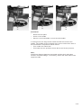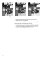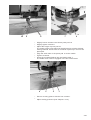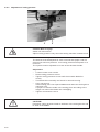
1
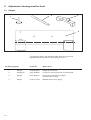
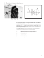
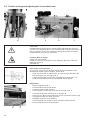
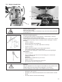
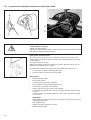
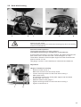
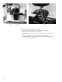
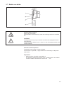
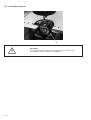
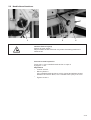
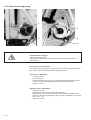
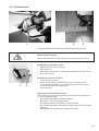
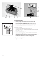
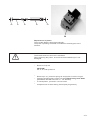
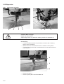
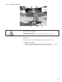
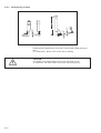
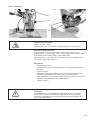
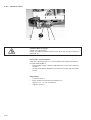
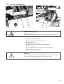
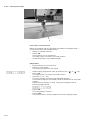
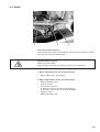
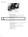
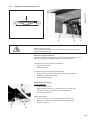
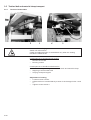
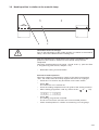
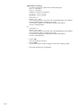
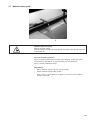
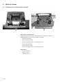
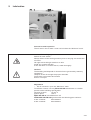
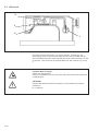
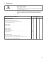
Contents
Page:
Part 3: Maintenance Instructions 739-23
1.
Introduction . . . . . . . . . . . . . . . . . . . . . . . . . . . . . . . . . . . . . . . . . . . . . . . . .
2.
2.1
2.2
2.3
2.4
2.5
2.6
2.7
2.8
2.9
2.10
2.11
2.12
2.12.1
2.12.2
2.12.3
2.12.4
2.12.5
2.12.6
2.12.7
2.12.8
2.13
2.14
Adjusting machine head . . . . . . . . . . . . . . . . . .
Gauges . . . . . . . . . . . . . . . . . . . . . . . . . . . . .
Description of integrated adjusting screw . . . . . . . . .
Position of integrated adjusting disc to arm shaft . . . .
Height of needle bar. . . . . . . . . . . . . . . . . . . . . .
Loop stroke and distance between hook tip and needle.
Alignment of hook drive housing . . . . . . . . . . . . . .
Bobbin case holder . . . . . . . . . . . . . . . . . . . . . .
Lubrication of hook . . . . . . . . . . . . . . . . . . . . . .
Needle thread tensioner . . . . . . . . . . . . . . . . . . .
Thread tensioning spring . . . . . . . . . . . . . . . . . . .
Thread scissors . . . . . . . . . . . . . . . . . . . . . . . .
Edge cutter . . . . . . . . . . . . . . . . . . . . . . . . . . .
Replacement of blades . . . . . . . . . . . . . . . . . . . .
Adjustment of cutting pressure . . . . . . . . . . . . . . .
Lubrication of blades . . . . . . . . . . . . . . . . . . . . .
Resharpening of blades . . . . . . . . . . . . . . . . . . .
Blade drive . . . . . . . . . . . . . . . . . . . . . . . . . . .
Reference switch . . . . . . . . . . . . . . . . . . . . . . .
Replacement of toothed belt . . . . . . . . . . . . . . . . .
Edge cutter zero point . . . . . . . . . . . . . . . . . . . .
Winder . . . . . . . . . . . . . . . . . . . . . . . . . . . . . .
Synchronizer . . . . . . . . . . . . . . . . . . . . . . . . . .
3.
3.1
3.2
3.3
3.4
3.4.1
3.4.2
3.5
3.5.1
3.6
3.7
Transport devices . . . . . . . . . . . . . . . . . . . . . . . .
Adjustment of linear guide to table-top . . . . . . . . . . . . .
Distance of material clamp guide to table-top. . . . . . . . .
Material clamp guide at right angles to bed-plate of sewing
Transport slide and toothed belt. . . . . . . . . . . . . . . . .
Replacement of toothed belt . . . . . . . . . . . . . . . . . . .
Tension of toothed belt . . . . . . . . . . . . . . . . . . . . . .
Toothed belt and material clamp transport . . . . . . . . . .
Tension of toothed belt . . . . . . . . . . . . . . . . . . . . . .
Needle position in relation to the material clamp . . . . . . .
Material clamp guide . . . . . . . . . . . . . . . . . . . . . . .
4.
4.1
.
.
.
.
.
.
.
.
.
.
.
.
.
.
.
.
.
.
.
.
.
.
.
.
.
.
.
.
.
.
.
.
.
.
.
.
.
.
.
.
.
.
.
.
.
.
.
.
.
.
.
.
.
.
.
.
.
.
.
.
.
.
.
.
.
.
.
.
.
.
.
.
.
.
.
.
.
.
.
.
.
.
.
.
.
.
.
.
.
.
.
.
.
.
.
.
.
.
.
.
.
.
.
.
.
.
.
.
.
.
.
.
.
.
.
.
.
.
.
.
.
.
.
.
.
.
.
.
.
.
.
.
.
.
.
.
.
.
.
.
.
.
.
.
.
.
.
.
.
.
.
.
.
.
.
.
.
.
.
.
.
3
.
.
.
.
.
.
.
.
.
.
.
.
.
.
.
.
.
.
.
.
.
.
.
.
.
.
.
.
.
.
.
.
.
.
.
.
.
.
.
.
.
.
.
.
.
.
.
.
.
.
.
.
.
.
.
.
.
.
.
.
.
.
.
.
.
.
.
.
.
.
.
.
.
.
.
.
.
.
.
.
.
.
.
.
.
.
.
.
.
.
.
.
.
.
.
.
.
.
.
.
.
.
.
.
.
.
.
.
.
.
.
.
.
.
.
.
.
.
.
.
.
.
.
.
.
.
.
.
.
.
.
.
.
.
.
.
.
.
.
.
.
.
.
.
.
.
.
.
.
.
.
.
.
.
.
.
.
.
.
.
.
.
.
.
.
.
.
.
.
.
.
.
.
.
.
.
.
.
.
.
.
.
.
.
.
.
.
.
.
.
.
.
.
.
.
.
.
.
.
.
.
.
.
.
.
.
.
.
.
.
.
.
.
.
.
.
.
.
.
.
.
.
.
.
.
.
.
.
.
.
.
.
.
.
.
.
.
.
.
.
.
.
.
.
.
.
.
.
.
.
.
.
.
.
.
.
.
.
.
.
.
.
.
.
.
.
.
.
.
.
.
.
.
.
.
.
.
.
.
.
.
.
.
.
.
.
.
.
.
.
.
.
.
.
.
.
.
.
.
.
.
.
.
.
.
.
.
.
.
.
.
.
.
.
.
.
.
.
.
.
.
.
.
.
.
.
.
.
.
.
.
.
.
.
.
.
.
.
.
.
.
.
.
.
.
.
.
.
.
.
.
.
.
.
.
.
.
.
.
.
.
.
.
.
.
.
.
.
4
4
5
6
7
8
9
11
12
13
14
15
18
18
22
23
24
25
26
27
28
29
30
. . . . . .
. . . . . .
. . . . . .
machine.
. . . . . .
. . . . . .
. . . . . .
. . . . . .
. . . . . .
. . . . . .
. . . . . .
.
.
.
.
.
.
.
.
.
.
.
.
.
.
.
.
.
.
.
.
.
.
.
.
.
.
.
.
.
.
.
.
.
.
.
.
.
.
.
.
.
.
.
.
.
.
.
.
.
.
.
.
.
.
.
.
.
.
.
.
.
.
.
.
.
.
.
.
.
.
.
.
.
.
.
.
.
.
.
.
.
.
.
.
.
.
.
.
.
.
.
.
.
.
.
.
.
.
.
.
.
.
.
.
.
.
.
.
.
.
.
.
.
.
.
.
.
.
.
.
.
.
.
.
.
.
.
.
.
.
.
.
.
.
.
.
.
.
.
.
.
.
.
.
.
.
.
.
.
.
.
.
.
.
.
.
.
.
.
.
.
.
.
.
.
31
31
32
33
34
34
35
36
36
37
39
Material clamps . . . . . . . . . . . . . . . . . . . . . . . . . . . . . . . . . . . . . . . . . . . . . . .
Clamping force of the material clamps . . . . . . . . . . . . . . . . . . . . . . . . . . . . . . . . . .
40
40
Contents
Page:
5.
5.1
Lubrication . . . . . . . . . . . . . . . . . . . . . . . . . . . . . . . . . . . . . . . . . . . . . . . . .
Oil circuit . . . . . . . . . . . . . . . . . . . . . . . . . . . . . . . . . . . . . . . . . . . . . . . . . . .
41
42
6.
Maintenance . . . . . . . . . . . . . . . . . . . . . . . . . . . . . . . . . . . . . . . . . . . . . . . . .
43
1.
Introduction
This maintenance manual describes the tasks for the adjustment of the
sewing machine in the appropriate sequence.
CAUTION!
Certain settings and positions are related to each other.
The individual adjustments must therefore be made in the instructed
sequence.
All maintenance work described in these instructions must be carried
out by suitably
trained and instructed staff!
Risk of damage!
Prior to the recommissioning of the sewing machine after dismantling,
carry out all necessary adjustments according to these instructions.
Prior to adjustments on the stitch-producing parts:
–
Insert new needle.
Caution! Risk of injury!
Prior to repairs, modifications and maintenance work:
– Switch off main switch and disconnect the sewing machine from the
pneumatic
supply network.
Exception:
Adjustments carried out with help of test or setting programmes.
Adjustments and function tests of running sewing machine
– Adjustments and function tests of the running sewing machine
require strict observation of all safety instructions and
greatest caution.
Adjustments of the needle
– To prevent injury, remove sharp and pointed parts before carrying
out the
adjustments.
Exception:
Parts are required for the respective adjustments.
3-3
2.
Adjustment of sewing machine head
2.1 Gauges
2
1
3
4
The gauges listed in the following table allow for the precise
adjustment and inspection of the sewing machine.
No.Setting gauge
3-4
Order No.
Application
1
Gauge
0216 001069
Height of needle bar
2
Setting pin
9301 022608
Locking of sewing machine in position A-F
3
Gauge
0271 000767
Height of needle bar and height
of hook drive housing
4
Gauge
0739 41 751 4
Material clamp zero gauge
2.2 Description of integrated adjusting screw
3
3
2
4
1
By means of the retention pin 3 and the adjusting disc 4 integrated in
the toothed belt wheel, the sewing machine can be locked in the
current setting positions.
The adjusting disc is equipped with 6 recesses that are labeled on the
hand wheel as A, B, C, D, E and F. In connection with the mark 1, the
letters indicate the position of the recesses at which the machine can
be locked by means of pin 3.
Recess A (loop stroke position) is deeper than the other recesses.
To adjust the individual positions, proceed as follows:
A
B
C
D
E
F
Adjusting disc to groove in the arm shaft crank,
loop stroke, distance of hook tip to needle.
not yet assigned !
Thread lever up
not yet assigned !
Height of needle bar
not yet assigned !
3-5
2.3 Position of integrated adjusting disc to arm shaft crank
4
3
2
1
CAUTION!
All adjustments carried out by means of the adjusting disc are only
correct, if the adjusting disc is set as described in these instructions. If
the arm shaft is moved, the following settings and position must be
inspected and corrected, if necessary.
Caution! Risk of injury!
Switch off main switch !
Check and correct the position of the adjusting disc only when the
sewing machine is
switched off.
Instruction and inspection
The groove 4 and the cut A of the adjusting disc integrated in the
toothed belt wheel must be aligned to line X - Y.
– Lock arm shaft with a retention pin or a Ø 5 mm pin placed in the
arm shaft groove 4 (through hole 3).
– It must be possible to insert the retention pin through hole 1 in
hand wheel position A into the integrated adjusting disc.
Adjustment
– Remove bobbin cover 2.
– Pull toothed belt from belt wheel.
– Loosen screws of belt wheel 6.
Insert hexagon socket key from the top through hole 5.
– Lock belt wheel with retention pin in position A.
– Insert a 5 mm Ø pin into positioning hole 3 and ensure that the pin
is engaged at the arm shaft groove 4.
– Retighten screws on belt wheel 6.
The belt wheel may thereby not be moved in axial direction.
– Pull toothed belt onto the belt wheel.
6
3-6
5
2.4 Height of needle bar
1
2
3
Caution! Risk of injury!
Switch off main switch.
Check and adjust height of needle bar only when the sewing machine
is switched off.
4
5
6
Instruction and inspection
In setting position A (loop stroke position) , the hook tip 4 must be
located at the centre of the needle scarf 5.
The adjustment of the height of the needle bar is carried out by means
of the measuring bridge 2 (0271 000766) and the setting pin 1 (0216
001069).
– Loosen screw 6.
– Remove needle from needle bar.
– Insert setting pin 1 into the needle bar to the stop.
– Tighten screw 6.
– Place measuring bridge 2 onto throat plate surface.
– Lock machine head in setting position A.
The foot of the setting pin 1 must touch the measuring bridge 2.
Adjustment
– Loosen screw 3.
– Move needle bar until the foot of the setting pin 1 touches the
measuring bridge 2.
Caution!
Do not distort needle bar as you move it.
– Tighten screw 3.
– Remove measuring bridge and setting pin.
– Re-install all removed components.
Caution!
After the adjustment of the height of the needle bar, the position of the
needle guard must be inspected and adjusted, if necessary.
Incorrect settings of the height of the needle bar may result in:
–
–
–
damage to the hook tip.
jamming of the bobbin thread between the needle and the needle
guard.
incorrect stitches and thread breakage.
3-7
2.5 Loop stroke and distance between hook tip and needle
4
3
5
3
2
1
Caution! Risk of injury!
Switch off main switch!
Adjust loop stroke and distance of the hook tip to the needle only when
the sewing machine is switched off.
6
Instruction and inspection
The loop stroke is the way the needle bar completes from the lower
dead centre to the point where the hook tip is positionled at the centre
of the needle.
The loop stroke is 1.8 mm.
When the sewing machine is locked in position A, the hook tip 6 is to
stand on the centre of the needle.
The distance between the hook tip 6 and needle must be 0.1 mm.
– Lock machine head in setting position A.
– Check position of hook tip to the needle.
Adjustment
– Remove throat plate..
– Insert new needle.
– Loosen securing screws of hook 5.
The screws are accessed through hole 3.
– Lock sewing machine in position A.
– Align hook tip 6 to the centre of the needle.
The distance between the hook tip 6 and the needle scarf must be
0.1 mm.
In this position, the distance between the hook 5 and the set collar
3 is 0.4 mm.
–
–
3-8
CAUTION!
If the distance is less than 0.4 mm, the hook drive housing must be
adjusted accordingly
(see chapter 2.6).
Tighten securing screws of hook 5.
Replace throat plate.
2.6 Hook drive housing
3
2
1
5
4
Caution! Risk of injury!
Switch off main switch.
Check and adjust position of hook drive housing only when the sewing
machine is switched off.
Instruction and inspection
The hook drive housing 6 is factory-aligned.
Only adjust the housing in exceptional circumstances!
If the hook drive housing is correctly aligned, the distance between the
back of the hook 2 and the set collar 1 must be approx. 0.4 mm.
The distance between the throat plate support and the thread tension
plate 5 must be 3.7 mm.
Use gauge 4 (order no. 0271 000767) to measure these distances.
Adjustment
Height of hook drive housing
– Remove counter screw 3.
Below the counter screw lies a stop screw.
– Loosen securing screws 6 of the hook drive housing 7.
– Adjust stop screw.
The distance between the throat plate support and the thread
tension plate 5 is 3.7 mm.
– Measure distance with gauge 4.
– Tighten securing screws 6 of the hook drive housing 7.
– Tighten counterscrew 3.
7
6
3-9
7
6
2
1
Distance between hook and set collar
– Loosen securing screws 6 of the hook drive housing 7.
– Move hook drive housing 7 to the side.
There must be a distance of 0.4 mm between the hook 2 and the
set collar 1.
– Tighten securing screws 6 of the hook drive housing 7.
– Check the distance from the hook tip to the needle and adjust, if
necessary (see chapter 2.5).
3-10
2.7 Bobbin case holder
Caution! Risk of injury!
Switch off main switch!
Adjust bobbin case holder only when the sewing machine is switched
off.
CAUTION!
The adjustment may only be carried out within the highlighted area 3
(see drawing).
In the area of the holder nose 1, there is a risk of breakage exists, due
to the hardness.
Instruction and inspection
The bobbin case holder is factory-aligned.
If the holder is replaced, it might however be necessary to adjust the
new holder.
Adjustment
– Adjust position of bobbin case holder 4.
The distance between the holder nose 1 of the bobbin case holder
4 and the bobbin case base 2 must be 0.6 +0.1 mm.
3-11
2.8 Lubrication of hook
1
CAUTION!
The 739-23 sewing machine is equipped with an oil-free hook.
The adjusting screw 1 has thus no function.
3-12
2.9 Needle thread tensioner
1
3
2
Caution! Risk of injury!
Switch off main switch !
Adjust needle thread tensioner only when the sewing machine is
switched off.
Instruction and inspection
Press axis 1 of the needle thread tension to open it
by approx. 1 mm.
Adjustment
– Loosen screw 3.
– Move cylinder 2.
If the needle thread tensioner is fully closed and without thread
between the tension discs, axis 1 should have a play of 0.3 mm.
– Tighten screw 3.
3-13
2.10 Thread tensioning spring
1
3
2
4
5
Caution! Risk of injury!
Switch off main switch!
Adjust thread tensioning spring only when the sewing machine is
switched off.
Instruction and inspection
The thread tensioning spring 1 must hold the needle thread tense until
the needle point has penetrated the sewing material.
Thread run adjustment
– Loosen screw 4.
– Turn bushing 3.
The thread tensioning spring 1 must hold the needle thread tense
until the needle point has penetrated the sewing material.
– Tighten screw 4.
Spring tension adjustment
– Loosen screw 5.
– Adjust tension by turning the tensioning bolt 2.
Depending on the sewing material and the thread properties, the
tension of the thread tensioning spring must be between 20 and 50
cN (1 cN = 1 g).
– Tighten screw 5.
3-14
2.11 Thread scissors
1
3
2
To replace and adjust the blades, dismantle the tread scissors.
Caution! Risk of injury!
Before dismantling the thread scissors, switch off the main switch.
Dismantling of thread scissors
– Swivel machine head to the left.
– Pull out hose 1.
– Unscrew screws 2 and 3, remove thread scissors and disconnect
the hoses 4 and 5.
5
4
Installation of thread scissors
– Connect hoses 4 and 5.
– Insert thread scissors carefully and tighten screws 2 and 3.
The hook-shaped blade of the thread scissors must run at the
centre of the slot in the throat plate!
– Connect hose 1.
Operational test of thread scissors
The functioning of the thread scissors can be tested by pressing key
“1" at the operating panel.
– Pull needle and bobbin threads to the left.
– Press key “1" at the operating panel.
The thread scissors are lifted for a short moment.
– Pull needle and bobbin threads through the gap below the thread
scissors.
Both threads are cut and then held by the blades.
3-15
6
6
11
12
13
10
9
8
7
14
Dismantling of blades
– Remove screws 7 and 10, remove covering plate 9 and
blade-guiding plate 8.
– Pull movable blade 6 downwards and remove it from the
blade-guiding plate 8.
This is necessary to ensure that the blade is no damaged.
– Loosen screws 14 and remove the fixed blade 11.
11
6
15
12
3-16
Installation of blades
– Unscrew fixed blade 11 and pressure plate 12.
The distance between the edge of the blade and the edge of the
guide plate is 3 mm.
– Remove pressure screw 13.
– Insert movable blade 6 into blade-guiding plate 8 from below.
Test smooth running of blade.
– Tighten pressure screw 13 and adjust to suitable cutting pressure.
The sewing threads are to be cut off with minimum pressure.
Complete test cut (see also chapter operational test).
The screw is slotted at the end and can be slightly widened for
proper fit.
– Replace covering plate 9.
– Tighten screws 7 and 10.
20
21
22
23
24
20
Replacement of piston
The movable blade is lifted pneumatically.
The piston operating the blade is installed in the body part of the
scissors.
CAUTION!
The thread surface of the hole is anodised.
When replacing the piston, ensure that the anodised layer is not
damaged!
–
Remove circlip 20.
CAUTION!
Pin 21 is under pressure!
–
–
–
–
Remove pin 21, pressure spring 22 and piston 23 with O-ring 24.
Lubricate thread surface of the hole with ESSO fluid grease S420.
(DÜRKOPP ADLER AG order no.: 791 000304)
To install piston, proceed in reverse order.
Complete test cut with sewing thread (test programme).
3-17
2.12 Edge cutter
2.12.1
Replacement of blades
4
3
2
1
7
6
5
Caution! Risk of injury!
Switch off main switch!
Adjust edge cutter only when the sewing machine is switched off.
Dismantling
– Loosen counternuts and turn pressure screws 2 and 3 back by
approx. two revolutions.
– Remove the four countersunk screws 1 and the cover plate 4.
– Turn belt wheel 5 until the movable blade 6 can be removed from
blade holder 7.
8
9
10
–
–
3-18
Remove screws 8.
Remove press pad 9 and fixed blade 10.
10
Installation
– Remove throat plate.
– Insert a new needle.
– Secure a new fixed blade 10 onto the knife holder.
In cutting mode, the edge cutter rotates around the centre of the
needle. The needle must be aligned at the centre of the stitch hole of
the fixed blade in all positions shown above.
– Turn needle into stitch hole.
– Turn blade into the positions shown above and check puncture.
Note:
Insufficient distance between the needle and the stitch hole edge
results in thread breakage. If necessary, rework the stitch hole on the
respective side.
3-19
15
–
–
Replace throat plate and slightly tighten throat plate screws.
Adjust the height of the fixed blade.
Allow for a distance of approx. 0.2 mm between the bottom edge of
the blade and the top of the throat plate.
In all three positions shown above, the fixed blade must be in contact
with the throat plate button 15 and rotate smoothly.
– Check the position of the fixed blade in relation to the throat plate.
To adjust its position, press a screwdriver against the fixed blade.
In all of the three positions shown above, it must not recede and
must at all times touch the throat plate button 15.
– Adjust throat plate and tighten throat plate screws.
3-20
10
9
8
–
–
–
–
–
–
6
Slightly loosen screws 8 and insert press pad 10.
Slightly tighten screws 8.
Adjust the height of press pad 10.
The height of the press pad must be adjusted to suit the thickest
sewing material. Ensure that no material is piled up in front of the
press pad.
Align the stitch hole of the press pad 10 to the needle.
Tighten screws 8.
Insert the movable blade 6 into the blade holder 7.
The blade drive must be engaged in the slot of the blade.
4
–
–
7
3
2
1
Secure covering plate 4 with the four screws 1.
Adjust cutting pressure (see chapter 2.12.2).
3-21
2.12.2
Adjustment of cutting pressure
3
2
Caution! Risk of injury!
Switch off main switch!
Adjust cutting pressure only when the sewing machine is switched off.
Instruction and inspection
The devices must be adjusted in such a manner that proper cuts are
achieved at minimum pressure. Low cutting pressures keep wear to a
minimum.
The system must be adjusted to cut two of the thickest threads.
Adjustment
– Loosen counter nuts 2 and 3.
– Reset cutting pressure screws.
– Tighten cutting pressure screws until the movable blade fits
closely.
– Turn blade drive manually and check for smooth running.
– Carry out test cut.
Insert sewing piece into opened blades and rotate the sewing drive
manually once.
A proper cut must be made in the sewing piece according to the
length over which the blades are overlapping.
– Tighten counternuts 2 and 3.
CAUTION!
Excessive cutting pressure leads to stiffness of the cutting device and
to wear of the blades.
3-22
2.12.3
Lubrication of blades
3
2
1
Caution! Risk of injury!
Switch off main switch!
Lubricate blades only when the sewing machine is switched off.
Instruction
The edge cutter must be lubricated daily with a few drops of oil.
Lubrication of blades
– Apply one drop of oil onto the pressure screws 1 and 2, the blade
edges 3 and the closely fitting surfaces of the blades.
3-23
Resharpening of blades
°
12
10
°
1 0°
2.12.4
Resharpen the blades that are made in hard metal (Widia) diamond
disc.
For dimensions, please refer to the above drawing.
CAUTION!
The height of movable blade may not be less than 50 mm,
as otherwise, the blade stroke cannot be adjusted properly.
3-24
2.12.5
Blade drive
1
2
3
4
Caution! Risk of injury!
Switch off main switch!
Adjust blade drive only when the sewing machine is switched off.
Instruction and inspection
If the eccentric 1 of the drive motor is at the lower dead centre,
approximately ¾ of the length of the cutting edge of the movable blade
must be below the cutting edge of the fixed blade.
Adjust blade bar 4 in such a way that there is an equal clearance at
both sides of the blade holder 3.
Adjustment
– Unscrew face cover.
– Turn eccentric 1 to the lowest position for the blade movement at
the motor.
– Loosen screw 2.
– Adjust the height of the blade bar 4 in such a way that ¾ of the
movable blade isbelow the cutting edge of the fixed blade.
– Adjust blade bar 4 to the side in such a way that there is an equal
clearance at both sides of the blade holder 3.
– Tighten screw 2.
CAUTION!
If the blades are not overlapping as described above, the cutting
performance may not be sufficient, especially with thick material.
Excessive overlapping may result in the sewing material piling up in
front of the edge cutter.
3-25
2.12.6
Reference switch
4
3
2
1
Caution! Risk of injury!
Switch off main switch !
Check and adjust reference switch only when the sewing machine is
switched off.
Instruction and inspection
Allow for a distance of 0.5 - 1.0 mm between the reference switch 2
and the blade holder 3.
– Place blade holder 3 with the belt wheel in front of the reference
switch 2.
– Check the distance between the reference switch and the blade
holder.
Adjustment
– Loosen screws 1.
– Move reference switch until a distance of
approx. 0.5 - 1.0 mm is reached.
– Tighten screws 1.
3-26
2.12.7
4
Replacement of toothed belt
3
2
1
5
4
Caution! Risk of injury!
Switch off main switch !
Replace toothed belt only when the sewing machine is switched off.
–
–
–
–
–
–
–
Remove guard plates 2 and 3.
Swivel sewing machine head to the left.
Remove screw 5.
The belt wheel is now loose.
Remove belt from drive wheel 1 and belt wheel 4.
Install new belt.
Secure belt wheel 4 with screw 5 on the blade holder.
Replace guard plates 2 and 3.
Caution!
After a replacement of the toothed belt, the zero point of the cutter
must be re-defined (for adjustment, see chapter 2.12.8).
3-27
2.12.8
Zero point of cutter
1
Instruction and inspection
When the material clamp is inserted, the blades of the edge cutter 1
must point towards the material clamp.
– Switch on sewing machine.
– Press “OK”.
The reference run is carried out.
The edge cutter is moved to its initial position.
– Check the position of the blades edges.
Adjustment
– Press and hold “F3" function key.
– Switch on main switch.
The setting programmes are called.
– Select setting programme “303" by means of the ” “ or “ “ key.
– Press “OK”.
The edge cutter is moved to its initial position.
– Press the “↓” or “” key.
The zero position is moved in the selected direction.
The last three digits of the display show its distance from the initial
position.
Adjust the zero position in such a way that the edge cutter is
pointing straight ahead.
–
–
3-28
Press “OK”.
The new position is saved.
Press “ESC”.
The system returns to the programme for basic settings (300).
2.13 Winder
3
2
1
Instruction and inspection
The winder must switch off automatically as soon as the bobbin is filled
up to 0.5 mm from the bobbin edge.
Caution! Risk of injury!
Switch off main switch!
Adjust winder only when the sewing machine is switched off.
1. Minor adjustments of the thread windings
– Bend bobbin flap 1 accordingly.
2.
–
–
–
Major adjustments of the thread windings
Remove bobbin cover.
Loosen screw 3.
Twist switching cam 2.
In direction of arrow A: less thread windings
In direction of arrow B: more thread windings
– Tighten screw 3.
– Replace bobbin cover.
3-29
2.14 Synchronizer
6
5
4
3
2
1
Instruction and inspection
After the thread is cut, the sewing machine should come to a halt in
position C of the adjusting disc.
The distance between the synchronizer 3 and the switching curve 4
must be approx. 0.5 mm to 1.0 mm.
Caution! Risk of injury!
Switch off main switch!
Adjust synchronizer only when the sewing machine is switched off.
Adjustment of settings
–
–
–
–
–
–
–
–
–
3-30
Loosen counternut 2.
Adjust distance between synchronizer 3 and the greatest outside
diameter of the switching curve.
Distance = 0.5 to 1.0 mm
Tighten counternut 2.
Lock sewing machine in position C of the adjusting disc.
Loosen screws 1 and 6.
Twist switching curve 5, so that the switching cam 4 is exactly in
line with the synchronizer 3.
Tighten screws 1 and 6.
Remove lock.
Check position after cutting.
3.
Transport unit
3.1 Adjustment of linear guide to the table-top
1
3
2
Instruction and inspection
During its run, the material clamp guide 1 must always have the same
distance to the table-top surface.
– Measure the distance between the guide and the table-top to the
left and to the right.
– Move the guide and measure distance again.
Caution! Risk of injury!
Switch off main switch!
Adjust parallel alignment of the guide only when the sewing machine is
switched off.
Adjustment
– Loosen screws 3 of the guide bars 2 below the table-top.
– Align guide bars 2 parallel to the bottom side of the table top and
tighten screws 3.
– Ensure that the material clamp guide is aligned to the surface of
the table-top.
3-31
3.2 Distance of material clamp guide to table-top
2
6
1
5
4
3
Instruction and inspection
The distance of the material clamp guide 1 to the surface of the
table-top 2 must be at least 2.5 mm. The distance must be the same
along the entire length of the guide.
– Check the distance between the guide to the table-top along its
entire length.
Caution! Risk of injury!
Switch off main switch!
Adjust guide only when the sewing machine is switched off.
Adjustment
– Loosen the four counternuts 7 on the left and right of guide 5.
– Adjust guide rollers 4 with the eccentrics 3 so that there is an equal
distance of 2.5 mm between the material clamp guide 1 and
table-top 2.
Caution!
Ensure that there is no play between the rollers 4 and the guide bars 6.
–
–
7
3-32
Position rollers 4 tightly onto the guide bars 6.
Tighten counternuts 7.
3.3 Material clamp guide at right angles to bed-plate of sewing machine
2
1
4
3
Instruction and inspection
The guide 1 must be at an angle of 90° degrees to the bed-plate of the
sewing machine 2.
– Measure the angle between the bed-plate 2 and the guide 1.
Caution! Risk of injury!
Switch off main switch!
Adjust guide only when the sewing machine is switched off.
Adjustment
– Loosen screws 3 at the left or right tension plate 4.
– Align tension plate 4 so that material clamp guide is at an angle of
90° degrees to the bed-plate of the sewing machine.
– Tighten screws 3 and check the angle of the guide.
4
3
3-33
3.4 Transport slide and toothed belt
3.4.1
4
Replacement of toothed belt
3
2
1
7
6
5
Caution! Risk of injury!
Switch off main switch!
Adjust guide only when the sewing machine is switched off.
Remove toothed belt
– Loosen counternuts 9 at the rear belt wheels.
– Relax tension of toothed belt.
– Loosen screws 1 and 5 at the connecting plates 2 and 6 of the
toothed belts.
– Remove toothed belts 3 and 7 from the front and rear belt wheels 4
and 8 respectively.
9
3-34
8
Positioning of toothed belt
– Insert toothed belt onto the front and rear belt wheels 4 and 8 and
screw the ends with the connecting plates 2 and 6 to the tension
plates.
– Adjust tension of toothed belt (see chapter 3.4.2).
3.4.2
Adjustment of toothed belt tension
3
2
1
Caution! Risk of injury!
Switch off main switch!
Check and adjust tension of toothed belt only when the sewing
machine is switched off.
Instruction and inspection
When the material clamp guide is in its end position at the front, it
should be possible to slightly squeeze the toothed belt.
Consequences of excessive belt tension
– Shorter service life
– Running noises
Consequences of insufficient belt tension
– Nonconforming meshing between belt teeth and wheel
– Skipping of teeth under load
– Varying stitch lengths
Adjustment of setting
Left toothed belt
– Loosen counternut 3.
– Adjust the belt wheel 2 by means of the nut at its rear.
Increase or reduce tension of the toothed belt 1.
– Tighten counternut 3.
Right toothed belt
– Loosen screws 4 on the securing plate of the motor.
– Move step motor 5 to adjust tension of toothed belt.
– Tighten screws 4.
5
4
3-35
3.5 Toothed belt and material clamp transport
3.5.1
Tension of toothed belt
2
1
4
3
Caution! Risk of injury!
Switch off main switch!
Check and adjust tension of toothed belt only when the sewing
machine is switched off.
Consequences of excessive belt tension
– Shorter service life
– Running noises
Consequences of insufficient belt tension
– Nonconforming meshing between belt teeth and material clamp
– Skipping of teeth under load
– Varying transport lengths
Adjustment of setting
– Loosen screws 2 and 3.
– Adjust tension of toothed belt by means of the hexagon bolts 1 and
4.
– Tighten screws 2 and 3.
3-36
3.6 Needle position in relation to the material clamp
2
1
CAUTION! Risk of breakage!
Prior to the adjustment of the needle position in relation to the material
clamp, remove the blades and the sewing foot.
After the adjustment or replacement of the belt is completed, the
position of the needle in relation to the material clamp must be
readjusted.
Check the needle position with gauge 1 (0739 41751 4) (see also Part
4: Programming Instructions, chapter 1.4.3).
–
Dismantle sewing foot and blades.
Instruction and inspection
When the needle is positioned by means of the setting programme
“302", the needle must be exactly aligned above hole 2 in gauge 1.
– Press the “F3" function key and switch on the main switch.
– Press “OK”.
The reference run is carried out.
– Insert the setting template into the X-guide of the sewing machine.
– Select setting programme “302" by means of the ” ” or “ ” key.
–
–
Press “OK”.
The setting programme is started.
The X and Y axes are moved to the current needle position.
Check needle position in relation to measuring 2 on the gauge.
3-37
Adjustment of setting
– To select a direction, press the corresponding key.
Key “1": X position
Key ”2": Y position
Example: Change of X position
–
Press key “3".
Press ”↓“ or ”“ key.
The needle position is moved in the selected direction and relative
to the material clamp in steps of 1/10 mm .
The last three digits of the display indicate the distance
from the initial position.
Or
– Press key “4".
Press ”↓“ or ”“ key.
The needle position is moved in the selected direction and relative
to the material clamp in steps of 5/10 mm .
The last three digits of the display indicate the distance
from the initial position.
–
–
–
3-38
Press “OK”.
The new position is saved.
Press “ESC”.
The system returns to the programme for basic settings (300).
Re-install sewing foot and blades.
3.7 Material clamp guide
1
Caution! Risk of injury!
Switch off main switch.
Check and adjust material clamp guide only when the sewing machine
is switched off.
Instruction and inspection
Screw 1 prevents the material clamp from slipping off the drive belt.
There must be a distance of approximately 0.5 mm between
screw 1 and the material clamp.
Adjustment
– Place material clamp onto the conveyor belt.
– Insert material clamp under guide 1.
– Turn screw 1 until a distance of approx. 0.5 mm to the material
clamp is reached.
3-39
4.
Material clamps
4.1 Clamping force of the material clamps
1
2
Instruction and inspection
Depending on the thickness of the material, it might occur that the
material holder cannot or only barely be closed.
– Insert thin material.
– Close material clamp.
–
–
–
–
Check clamping force and closing pressure.
Insert thick material.
Close material clamp.
Check clamping force and closing pressure.
Adjustment
– Loosen screws 1.
– Adjust angle 2.
– Tighten screws 1.
3-40
5.
Lubrication
1
Instruction and inspection
The oil level in the oil tank 1 must not be below the “Minimum” mark.
Caution! Risk of injury!
Switch off main switch!
Always switch off the sewing machine prior to carrying out work at the
oil circuit.
Oil might cause allergic reactions on skin.
Avoid any contact with skin.
If skin has been in contact with oil, wash thoroughly.
Caution!
The handling and disposal of mineral oils are governed by statutory
regulations.
Dispose of the oil through the proper channels.
Protect the environment and ensure
that no oil is spilt.
Adjustment
– Fill oil into tank 1 up to the “Maximum” mark.
To refill the oil tank, use only ESSO SP-NK 10 lubricant or a similar
product of the following specification:
Viscosity at 40°C:
10 mm 2 /s
Ignition point:
150°C
ESSO SP-NK 10 is available from all
DÜRKOPP ADLER AG agencies with the following part numbers:
2 litre container:
9047 000013
5 litre container:
9047 000014
3-41
5.1 Oil circuit
4
3
1
2
1
The oil runs from the oil tank 1 to the oil sump 3. From there, the
lubricating points in the arm and head sections are provided with oil.
The oil emitted from the crank mechanism flows via the oil wick 2 to the
oil sump 3. The excess oil is pumped back into the oil tank 1 by pump
4.
Caution! Risk of injury!
Switch off main switch!
Carry out installations on the oil circuit only when the sewing machine
is switched off.
CAUTION!
Ensure that the hose ends are properly re-connected to the pump.
S=Suction
D = Pressure
3-42
6.
Maintenance
Caution! Risk of injury!
Switch off main switch!
The maintenance of the sewing machine may only be carried out when
the machine is switched off.
Maintenance tasks to be carried out daily or weekly respectively by the
operating personnel (cleaning and lubrication) are described in the
operating instructions (Part 1). They are also listed in the following
table.
Maintenance task to be carried out
8
Operating hours
40
160
500
Sewing machine head
- Remove sewing dust and threads . . . . . . . . . . . . . . . . . . . . . . . . . . . . . . .
X
- Check oil level in the oil tank for lubrication of
the sewing machine head . . . . . . . . . . . . . . . . . . . . . . . . . . . . . . . . . . . . . .
X
Switch cabinet
- Clean air filter. . . . . . . . . . . . . . . . . . . . . . . . . . . . . . . . . . . . . . . . . . . . . . . . .
X
Waste container
Suction system
- Empty waste container . . . . . . . . . . . . . . . . . . . . . . . . . . . . . . . . . . . . . . . . .
X
- Clean dust bag . . . . . . . . . . . . . . . . . . . . . . . . . . . . . . . . . . . . . . . . . . . . . . . .
X
Pneumatic system
- Check water level in the pressure regulator . . . . . . . . . . . . . . . . . . . . . .
X
- Clean filter cartridge of the compressed air maintenance unit . . . . . .
X
- Check tightness of the pneumatic system . . . . . . . . . . . . . . . . . . . . . . . .
X
3-43