1
EV 30i
INVERTER GENERATOR
(E
( !
.....:6
MANUAL
Inverter Generator
EV 30i
PREFACE
Thank you for purchasing our generators.
This manual covers operation and maintenance of the EV30i generator.
All information in this publication is based on the latest product information
Available at the time of approval for printing.
We reserve the right to make changes at any time without notice and without
incurring any obligation.
No part of this publication may be reproduced without written permission.
This manual should be considered a permanent part of the generator and should
remain with it if it is resold.
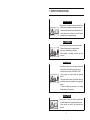
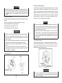
Pay special attention to statements preceded by the following words;
Failure to properly follow these precautions can result in
property damage, serious injury or DEATH!
Read all labels and the owner's manual before operating
this generator.
Operate only in well ventilated areas. Exhaust gas
Contains poisonous carbon monoxide, and can be
deadly. Always stop engine before refuelling. Wait 5
minutes before restarting.
Check for spilled fuel or leaks. Clean and/or repair before
use.
Keep any sources of ignition away from fuel tank, at all
times.
Indicates a strong possibility of severe personal injury or
death if instructions are not followed.
Indicates a possibility of personal injury or equipment
damage if instructions are not followed.
NOTE: Gives helpful information.
If a problem should arise, or if you have any questions about the generator,
consult an authorized dealer.
Our generators are designed to give safe and dependable
service if operated according to instructions. Read and
understand the Owner's Manual before operating the
Failure to do so could result in personal injury or
equipment damage.
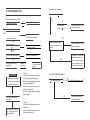
CONTENTS
1.SAFETY INSTRUCTIONS - - - - - - - - - - - - - - - - - - - - - - - - - - - - - · 1
2.SAFETY LABEL LOCA TIONS --------------------------------------3
3.PRE-OPERATION CHECK --------------------------------------- 5
4.STAR TING THE ENGINE - - - - - - - - - - - - - - - - - - - - - - - - - - - - - · 8
5.GENERAT OR USE - - - - - - - - - - - - - - - - - - - - - - - - - - - - - - - - - · 11
6.STOPPING THE ENGINE - - - - - - - - - - - - - - - - - - - - - - - - - - - - - · 14
7.MAINTENANCE -------------------------------------------------- 15
8. TRANSPORTI NG/STORAGE --------------------------------- 21
9.TROUBLESHOOTI NG ------------------------------------------ 22
1O.SPECIFICATIONS ------------------------------------------ 24
11.WIRING DIAGRAM ------------------------------------------ 25
12.WHEEL KIT-----------------------------------------------------------26
13. APPENDIX ------------------------------------------------- 27
1. SAFETY INSTRUCTI ONS
A.WARNING
•Our generators are designed to give safe and dependable service if operated according to instructions.
Read and understand the Owner's Manual before operating the generator. Failure to do so could result in
personal injury or equipment damage.
A.WARNING
• Exhaust gas contains poisonous carbon monoxide.
Never run the generator in an enclosed area.
Be sure to provide adequate ventilation.
When installed in ventilated protection are to be
observed.
A.WARNING
•The muffler becomes very hot during operation and
remains hot for a while after stopping the engine.
Be careful not to touch the muffler while it is hot.
Let the engine cool before storing the generator
indoors.
The engine exhaust system will be heated during operation and remain hot immediately after stopping the
engine.
To prevent scalding, pay attention to the warning
marks attached to the generator.
A.CAUTION
•Never connect a cable other than the special cable
for parallel operation to the parallel operation socket.
Electric shocks can result if this instruction is not
followed.
-1-
To ensure safe operation--
2. SAFETY LABEL LOCATI ONS
AWARNING
• Gasoline is extremely flammable and explosive under certain conditions.
Refuel in a well ventilated area with the engine stopped.
• Keep away from cigarette, smoke and sparks when refueling the generator.
Always refuel in a well-ventilated location.
• Wipe up spilled gasoline at once.
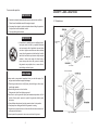
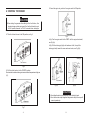
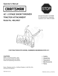
2.1 Outside view
AWARNING
• Connections for standby power to a building's electrical system must be made by a qualified electrician
and must comply with all applicable laws and electri
cal codes. Improper connections can allow electrical
current from the generator to back feed into the utility
lines.Such back feed may electrocute utility company
workers or others who contact the lines during a
power outage, and when utility power is restored,
the generator may explode, burn, or cause fires in
the buildings electrical system.
Maintenance
cover
Control panel
Air intake hole
Air cleaner
Fuel level indicator
AWARNING
•Always make a pre-operation inspection before you start the engine. You
may prevent an accident or equipment damage.
• Place the generator at least 1m(3ft) away from buildings or other equip
ment during operation.
•Operate the generator on a level surface.
If the generator is tiled, fuel spillage may result.
•Know how to stop the generator quickly and understand operation of all the
controls. Never permit anyone to operate the generator without proper
instrucions.
• Keep children and pets away from the generator when it is in operation.
• Keep away from rotating parts while the generator is running.
•The generator is a potential source of electrical shocks when misused; do
not operate with wet hands.
•Do not operate the generator in rain or snow and do not let it get wet.
-2-
Start grip
Air Exhaust hole
Fig1. Outside view
-3-
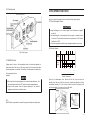
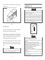
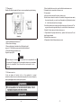
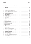
2.2 Control panel
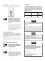
3. PRE-OPERATI ON CHECK
SMART throttle switch
Be sure to check the generator on a level surface with the engine stopped.
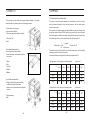
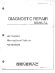
3.1 Check the engine oil level.
A.CAUTION
•Using nondetergent oil or 2-stroke engine oil could shorten the engine's
service life.
•Use high-detergent , premium quality 4-stroke engine oil, certified to meet
or exceed U.S. automobile manufacturer's requirements for API Service
Classification SG,SF.
• Select the appropriate viscosity for the average temperature in your area
SAE Viscosity Grades
>OW
Fig 2. Control panel
20W
Single
viscosity
20
2.3 SMART throttle
30
Engine speed is kept at idle automatically when the electrical appliance is
disconnected and it will return to the proper speed by the electrical load when
electrical appliance is connected. This position is recommended to minimize the
Fuel consumption while in
operation
Multiviscosity
"
-20-
A.NOTE
•When high electrical load appliances are connected simultaneously , turn
the smart throttle switch to the OFF position to reduce voltage changes.
• Smart throttle system does not operate sufficiently if the electrical
appliance equires the much electric power.
-10
.,
'"
10
- '"
"
100 'F
20
30
40 'C
Ambient Temperature
Open the oil maintenance cover. Remove the oil filler cap, and wipe the
dipstick with a clean rag. Check the oil level by inserting the dipstick in the filler
hole without screwing it in. If the oil level is below the end of the dipstick, refill
with recommended oil up to the top of the oil filler neck.
OFF:
SMART throttle system does not operate. Engine speed is kept over rated speed.
Lower limit
-4-
Fig.3
5
-
Gasoline’s containing alcohol
.A.CAUTION
•Running the engine with insufficient oil can cause serious engine damage.
•The Low Oil Alarm System will automatically stop the engine before the oil
level falls below the safe limit. However, to avoid the inconvenience of an
unexpected shutdown, it is still advisable to visually inspect the oil level
regularly.
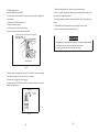
3.2 Check the fuel level
Use automotive gasoline (Unleaded is preferred to minimize combustion chamber
deposits).
If the fuel level is low, refill to the shoulder of the fuel strainer, see fig. 4.
Never use an oil/gasoline mixture or dirty gasoline.
Avoid getting dirt, dust or water in the fuel tank.
After refuelling, tighten the fuel filler cap securely.
.A.WARNING
•Gasoline is extremely flammable and is explosive under certain conditions.
•Refuel in a well-ventilated area with the engine stopped. Do not smoke or
allow flame or sparks in the area where the engine is refueled or where
gasoline is stored.
•Do not overfill the fuel tank (there should be no fuel in the filler neck). After
refueling, make sure the fuel filler cap is closed properly and securely.
•Be careful not to spill fuel when refueling. Spilled fuel or fuel vapor may
ignite.
If any fuel is spilled, make sure the area is dry before starting the engine.
•Avoid repeated or prolonged contact with skin or breathing of vapor. KEEP
OUT OF REACH OF CHILDREN.
If you decide to use a gasoline containing alcohol (gasohol), be sure its octane
rating is at least as high as that recommended by us. There are two types of
"gasohol": one containing ethanol, and the other containing methanol. Do not use
gasohol that contains more than 10% ethanol. Do not use gasoline containing
methanol (methyl or wood alcohol) that does not also contain solvents and
corrosion inhibitors for methanol. Never use gasoline containing more than 5%
methanol, even if it has solevents and corrosion inhibitors.
A.NOTE
•Fuel system damage or engine performance problems resulting from the
use of fuels that contain alcohol is not covered under the warranty. We
cannot endorse the use of fuels containing methanol since evidence of
their suitability is as yet incomplete.
• Before buying fuel from an unfamiliar station, try to find out if the fuel
contains alcohol, if it does, confirm the type and percentage of alcohol
used. If you notice any undersirable operating symptoms while using a
gasoline that contains alcohol, switch to gasoline that you know does not
contain alcohol.
3.3 Check the air cleaner
Check the air cleaner elements to be sure they are clean and in good condition.
Open the left side maintenance cover. Remove the air cleaner cover, remove the
paper element from the air cleaner cover, and check the both elements, clean or
replace the element(s) if necessary, see fig.5.
Fuel tank capacity: 13L
Oil surface
Oil surface
Fig. 5
.A.CAUTION
Strainer
Fig.4
-6-
•Never run the engine without the air cleaner. Rapid engine wear will
result from contaminants, such as dust and dirt, being drawn through the
carburetor, into the engine.
-7-
4.3 Insert the engine key, and turn the engine switch to ON position.
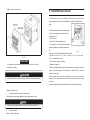
4. STARTING THE ENGINE
A CAUTION
•When starting the generator after adding fuel for the first time, after
longterm storage, or after running out of fuel, tum the fuel valve lever to
the "ON" position, then wait for 10 to 20 seconds before starting the
4.1 Turn the fuel valve lever to the ON position, see fig.6.
Fig.8
4.4(a) Turn the engine switch to the START until the engine has started,
see Fig.9(a).
4.4(b) Pull the starter grip lightly until resistance is felt, then pull the
starter grip briskly toward the arrow as shown below, see Fig. 9(b).
Starter grip
Fuel valve lever
Fig.6
4.2 Pull the choke knob out to the CLOSED position
Do not use the choke when the engine is warm or the air temperature is high, see
fig.7.
Engine switch
Fig.9(a)
Fig.9(b)
A.CAUTION
•Do not allow the starter grip to snap back. Return it slowly by hand.
•Do not let the starter rope rub against the generator body or the rope will
wear out prematurely.
Fig.7
-8-
-9-
4.5 Push the choke k n o b to the OPEN p o s i t i o n as the engine w a r m s
5. GENERATOR
Up, see page 10.
USE
.A.WARNING
•To prevent electrical shock from faulty appliances, the generator should be
grounded. Connect a length of heavy wire between the generator's ground
terminal and an external ground source.
•Connections for standby power to a building's electrical system must be
made by a qualified electrician and must comply with all applicable laws
and electrical codes. Improper connections can allow electrical current from
the generator to backfeed into the utility lines. Such backfeed may
electrocute utility company workers or others who contact the lines during a
power outage, and when utility power is restored, the generator may explode,
burn, or cause fires in the building's electrical system.
'A --l
Fig.10
High altitude operation
At high altitude, the standard carburettor air-fuel mixture will be excessively rich
Performance will decrease, and fuel consumption will increase.
Ground
terminal
High altitude performance can be improved by installing a smaller diameter main
fuel jet in the carburettor and readjusting the pilot screws. If you always operate the
generator at altitudes higher than 1,500 m (5,000 feet) above sea level, have
your authorized dealer perform these carburettor modifications.
Even with suitable carburettor jetting, engine horsepower will decrease
approximately 3.5% for each 305 m (1.000 feet) increase in altitude. The effect of
altitude on the horsepower will be greater than this if no carburettor modification is
made.
.ACAUTION
•Operation of the generator at an altitude lower than the carburetor is jetted
for may result in reduced performance, overheating, and serious engine
damage caused by an excessively lean air/fuel mixture.
l
.
.ACAUTION
• Limit operation requiring maximum power to 30 minutes.
For continuous operation do not exceed the rated power.
In either case, the total wattage of all appliances connected must be
considered.
•Do not exceed the current limit specified for any one receptacle.
•Do not connect the generator to a household circuit. This could cause the
damage to the generator or to electrical appliances in the house.
•Do not modify or use the generator for other purposes than it si intended for
Also observe the following when using the generator.
.Do not connect generators in parallel.
.Do not connect an extension to the exhaust pipe.
• When an extension cable is required, be sure to use tough rubber sheathed
flexible cable.
•Limit length of extension cables; 60 m for cables if 1.5mm2 and 1OOm for
cables of 2.5 mm2
•
• Keep the generator away from other electric cables or wires such as commercial power supply lines.
-10-
-11-
5.1 AC applications
1. Start the engine and make sure the green output indicator light comes on.
2. Confirm that the appliance to be used is switched off and plug in the appliance.
5.3 DC application
The DC receptacle may be used for charging 12 volt automotive-type batteries only.
Output voltage is 15-30V when current receptacle on no load. DC output will vary
according to the position of the Smart throttle switch. When the Smart throttle switch
is turned to the ON position and the AC output is not used, the DC current will be
about one-third of the rated current.
DC current:
OFF
I
EV30i
A
CAUTION
• Substantial overloading that continuously lights the red
overload indicator light may damage the generator.
Marginal overloading that temporarily lights the
overload indicator may shorten the service life of the
generator.
• Be sure that all appliances are in good working order
before connecting them to the generator. If an
appliance begins to operate abnormally, becomes
sluggish, or stops suddenly, turn off the generator
engine switch immediately. Disconnect the appliance
and examine it for signs of malfunction.
8.3A
ON
{do not use the AC output)
approximately 2.BA
1.Connect the charging cable to the DC receptacle of the generator and then to the
b tt
t . I
A.WARNING
• To prevent the possibility of creating spark near the battery, connect charging cable first to the generator, then to the battery. Disconnect cable first at
the battery.
•Before connecting charging cable to a battery that is installed in a vehicle,
disconnect the vehicles grounded battery cable. Reconnect the vehicle's
grounded battery cable after the charging cables are removed. This proced
dure will prevent the possibility of a short circuit and sparks if you make ace
idental contact between a battery terminal and the vehicle's frame or body.
5.2 Output and Overload Indicators
The green output indicator light will remain ON during normal operating conditions. If
the generator is overloaded or if there is a short in the connected appliance the
output indicator will go OFF and the overload indicator will go ON and current to the
connected appliance will be shut off.
Stop the engine if the overload indicator light comes ON and investigate the
overload source. The engine will continue to run even though it is not producing any
AC power. The engine must be stopped and then the generator restarted to resume
normal operation.
Check the engine oil level if the red oil alarming indicator comes ON.
A NOTE
•Before connecting an appliance to the generator, check
that it is in good order, and that its electrical rating does
not exceed that of the generator.
Then connect the po wer cord of the appliance, and
start the engine.
A NOTE
• When an electric motor is started, both the overload
indicator light and the output indicator light may go on
simultaneously. This is normal if the overload indicator
light goes off after about four seconds. If the overload
indicator light stays on, consult your dealer.
-12-
A.CAUTION
•Do not attempt to start an automobile engine with the generator still connected to batter. The generator may be damaged.
•Connect the positive battery terminal to the positive charging cord. Do not
reverse the charging cables, or serious damage to the generator and/or
battery may occur.
A.WARNING
•The battery gives off explosive gases; keep sparks, flames and cigarettes
away. Provide adequate ventilation when charging.
•The battery contains sulfuric acid {electrolyte). Contact with skin or eyes
may cause severe burns. Wear protective clothing and a face shield.
A. If electrolyte gets on your skin, flush with water.
B. lf electrolyte gets in your eyes, flush with water for at least 15 minutes
and call a physician.
•Electrolyte is poisonous.
A. If swallowed, drink large quantities of water or milk and follow with milk of
magnecia or vegetable oil and call a physician.
• Keep out of reach of children.
-13-
2. Start the engine
•The DC receptacle may be used while the AC power is in use.
7. MAINTENANCE
•An overloaded DC circuit will trip the DC circuit protector (push button comes
out). If this happens, wait a few minutes before pushing in the circuit
protector to resume operation.
The purpose of the maintenance and adjustment schedule is to keep the
generator in the best operating condition.
AWARNING
•Shut off the engine before performing any maintenance. If the engine must
be run, make sure the area is well ventilated. The exhaust contains poisonous carbon monoxide gas.
• Use genuine our parts or the equivalent. The use of replacement parts
which are not of equivalent quality may damage the generator.
Mai1lenanoe Schedule
REGULAR SERVICE PERIOD (1) Perform at every
indicated month or operating
hour interval,whichever oocursfirst
6.STOPPING THE ENGINE
ITEM
Engine oil
To stop the engine in an emergency tum the enginesswitch
OFF. In normal use:
Air deaner
Check
Change
""'
Check
Clean
1. Switch off the connected equipment and pull the inserted plug.
2. Tum off the engine switch.
3. Tum the fuel valve lever to the OFF position.
Spark plug
Clean-adjust
Sparkarrester
Clean
Fuelsedimentcup Clean
alve dearanc:e Check-adjust
Fueltankand straine Clean
Fuelline
·
Check
EACH
USE
FIRST EVERY3 EVERY 6 EVERY
MONTH MONTHS MONTHS YEAR
OR
OR
OR
OR
20 HRS 50 HRS 100HRS 300HRS
0
0
0
0
0 (2)
0
0
0
Q C3)
0 (3)
Every 2 years (Replace if necessary)(3)
NOTE: (1) Log hours of operation to determine proper maintenance.
(2) Service more frequently when used in dusty areas.
(3) These it ems should be serviced by an authorized dealer, unless the
owner has the proper tools and is mechanically proficient. See the
Shop Manual.
7.2 Changing oil
Drain the oil whil e the engine is still warm to assure rapid and complete draining.
OH drain bolt
Oildispstick
Fig.13
1. Open the left side maintenance cover.
2. Take out the oil outlet plug.
3. Remove the drain bolt, and drain the oil. Retighten the bolt
securely. 4. Refill with the recommended oil and check the level.
5. Close the left side maintenance cover.
Engine oil capacity 0.55L
1.Revolve the left side cover knob; open the left side maintenance cover.
2. Unsnap the clips, remove the air cleaner cover.
3. Foam element:
• Remove the foam element from the air cleaner cover.
•Wash the foam element in a solution of household detergent and warm water,
then rinse thoroughly, or wash in non-flammable or high flashpoint solvent.
AL- low the foam element to dry thoroughly.
•Soak the foam element in clean engine oil and squeeze out the excess oil. The
engine will smoke during initial startup if too much oil left in the foam element.
• Reinstall the foam element to the air cleaner cover.
4. Paper element: If the paper element is dirty, replace it with a new one. Do not
clean the paper element.
5.Reinstall the air cleaner cover.
6. Close and latch the left side maintenance cover.
A NOTE
•Please dispose of used motor oil in a manner that is compatible with the
environment. We suggest you take it in a sealed container to your local service
station for reclamation. Do not throw it in the trash or pour it on the
Round.
7.3 Air cleaner service
A dirty air cleaner will restrict air flow to the carburettor to prevent
carburettor malfunction, service the air cleaner regularly. Service more frequently
when operating thegenerator inextremely dusty areas.
•Never run the generator without the air cleaner.Rapid engine wear may result
-16-
-17-
7.5 Spark plug service
7. Install the spark plug carefully, by hand, to avoid cross-threading.
Recommended spark plug: WR7DC
8. After a new spark plug has been seated by hand, it should be tightened 1/2 tum
To ensure proper engine operation, the spark plug must be properly gapped and
with a wrench to compress its washer.
free of deposits.
If a used plug is being reinstalled, it should only require 1/8 to 1/4 turn after being
1. Open the left side maintenance cover.
seated.
2. Remove the spark plug cap.
9. Reinstall the spark plug inspection cover and tighten the cover screw.
3. Use the wrench to remove the spark plug.
10. Close and latch the left side maintenance cover.
4. Clean any dirt from around the spark plug base.
A.CAUTION
•The spark plug must be securely tightened. An improperly tightened plug
can become very hot and possibly damage the generator.
• Never use a spark plug with an improper heat range.
Spark plug lover
Fig.14
5. Visually inspect the spark plug. Discard it if the insulator is cracked or chipped.
Clean the spark plug with a wire brush if it is to be reused.
6. Measure the plug gap with a feeler gauge.
The gap should be 0.5-0.75mm (0.02-0.03in). Correct as necessary by carefully
bending the side electrode.
Plug gap
t
0.5-0.75mm
(0.02-0.03in)
Fig. 15
-18-
-19-
7.6 Spark arrester maintenance
8. TRANSPORTING/STORAGE
8.1 When t r a n s p o r t i n g t h e generator, tum the fuel v a l v e lever O F F and
keep the generator level to prevent fuel spillage. Fuel vapour or spilled fuel may
ignite.
8.2 Before storing the unit for an extended period:
1.Be sure the storage area is free of excessive
humidity and dust.
2. Drain the fuela. Open the left side maintenance cover.
b. Turn fuel valve lever to ON and then loosen the
carburettor drain screw. Drain the gasoline from
the
Carburettor and fuel tank and store in a suitable container.
Fig. 16
A.WARNING
c.Tighten the c a r b u r e t t o r
Fig. 17
screw, close t h e f u e l v a l v e
lever a n d
l e f t s i d e maintenance cover.
3. Once a month, recharge the battery.
• If the generator has been running, the muffler will be very hot. Allow it to
4. Change the engine oil.
cool before proceeding.
5. Remove the spark plug and pour about a tablespoon of clean engine oil into the
cylinder. Crank the engine several revolutions to distribute the oil, and then
reinstall the spark plug.
6.Slowly pull the starter grip until resistance is felt. At this point, the piston is
•The spark arrester must be serviced every 100 hours to maintain its efficiency.
coming up on its compression stroke and both the intake and e x h a u s t valves
are closed.
Storing the engine in this position will help to protect it from internal corrosion.
1.Remove the back cover.
2.
Remove the exhaust tail pipe and spark arrester.
3. Use a brush to remove carbon deposits from the spark arrester screen.
• Inspect the spark arrester screen for holes or tears. Replace if necessary.
4.
Reinstall the spark
arrester. 5. Reinstall the upper
back cover.
-20-
-21-
Appliance does not operate:
9. TROUBLESHOOTING
Is the output indicator light ON?
When the engine will not start
Is there fuel in the tank?
iYES
NO
YES
11ol Refill the fuel tank.
NO
NO
Is the overload
indic ator light ON?
Take the generator to an
authorized dealer.
NO
Turn the engine switch on.
Isthe engineswitch oo?
YES
Is the fuel valve on?
i
YES
Check the electrical appliance or equipment for any
defects.
NO
11o l Tum the fuel valve on.
NO
Take the generator to an
authorized dealer.
YES
Is the enough oil in the engine?
NO
YES
YES
Is there a spark from the
spark plug?
A WARNING
• Be sure there is no spilled
fuel around the spark plug
Spilled fuel may ignite.
Replace the
spark plug.
Take the generator
to an authorized
dealer.
To check:
1) Remove the spark plug cap and clean
any dirt from around the spark plug.
2) Remove the spark plug and install the
spark plug in the plug cap.
3) Set the plug side electrode on the
cylinder head to ground.
4) Crank the engine, sparks shouldjump
aaoss the gap.
Is the fuel reaching the
carburetor?
,,
If the ergine still does not
start. take the generator to an
authorized dealer.
•Replace the electrical
appliance or equipment
•Take the electrical appliance or equipment to an
electrical shop for repair
11o l Add the recommended oil.
To check:
1) Tum off the fuel valve and lossen the
drain screw.
2) Fuel should flow from the drain when
the fuel valveIs turned on.
No electricity at the DCreceptacle:
.
1s_o
_c ci_rc""Tu"i"t_p_ro_te
_c_to_r_o_n_?
t--- --•I Tumthe DC circuit protector on. I
NO
YES
Take the generatorto an
authorized dealer.
-22-
-23-
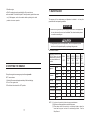
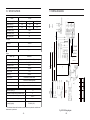
10. SPECIFICATIONS
11. WIRING DIAGRAM
Model
Rated frequency (Hz)
EV 30i
50
0
60
60
Rated voltage (V)
230
120
240
Rated current (A)
12.2
23.3
11.7
3600
Rated speed (rpm)
Rated output (kVA)
2.8
Max. output (kVA)
3.0
i1 I
g
0
' ,r,
::::J
rn
5j
DC voltage
12V-8.3A
Electric circuit breaker
rn
Without
ffi
0
,
a:
Model Type
rn
MA, ---- 0
Trigger winding
KG205GETi
Single cylinder, 4 stroke, vertical, air-cooled, OHV,gasoline engine
Displacement (Borex Stroke)
196ml (68 x 54mm)
Compression ratio
8.5:1
Rated power [kW(Hp)/(r/min)]
Ignition system
..
0
rn
!
.A
.•\.A.
Ignition coil
w
()
T. C. I
Spark plug
WR7DC
Starting system
Recoil starter, Electric starter
Fuel
Automotive unleaded gasoline
@
395
@
Fuel consumption (g /kW.h)
Lube oil
-
rn
4.0/3600
-------------C
L o w o il s w it c h
r
&
Engine
.,.
i s
Single phase
Phase number
Type
ffi
--- I
DC output
CD grade or SAE 10W-30, 15W-40
Fuel tank capacity (L)
13
Continuous running time (hr) (at rated output)
6
Noise level(zero load- full load) [dB(A)/7m]
8
@
@J
62-66 *
Dry weight [kg(lbs))
EV30i: 60 (132)
*: The declared values shall consider uncertainties due to production variation and
measurement procedures.
-24-
I
u.
u.
0
EV30i:686 X 425 X 495(27.01 X 16.73 X 19.49)
Overall dimension (LX W X H) [mm(in)]
T
Fig.18 EV30i Wiring diagram
-25-
z
0
t-
a:
;'<:
if)
12. WHEEL KIT
13. APPENDIX
The unit comes with the rubber mounting feet already installed. If you wish to
install the wheel kit, please perform the following procedure.
(1) Remove the mounting feet
a. Remove the bolt M8X16.
b. The mounting feet should drop off easily
1. The choice of the electric cable
The choice of the electric cable depends on the allowable current of the cable
and the distance between the load and the generator. And the cable section
should be big enough.
If the current in the cable is bigger than the allowable current, it will become over
hot and the cable will be burnt. If the cable is long and thin, the input voltage of
the electric appliance will be not enough, causing that the generator doesn't start.
Inthe following formula, you can calculate the value of the potential "e".
1. Mounting Foot
2.Bolt
(2) Install the W heel Assembly
a. Insert the axle into two brackets.
b. Install the washer, wheel,washer, and lock
pin in order.
.
1
Length
Potential (v)= -x
x Current (A) x
58
Section area
The relations among of the allowable current, and length, section of the Insulating
cable (single core, multi-core) are as follow:
(Presume that the use voltage is220V and the potential isbelow 1OV.
The application of the single-core insulating cable
1.Wheel
2.Axle
3. Lock pin
4. Washer
5. Bracket
h
c
(3) Install the wheel assembly
a. Align the bolts in the brackets with the
holes in the bottom of the chassis
b. Insert four bolts in each bracket and tighten
securely
75m
100m
125
150
200
SOA
8
14
22
22
30
38
22
30
38
50
50
60
200A
60
60
60
80
100
125
300A
100
100
100
125
150
200
The application of the multi-core insulating cable
th
SOA
-26-
SOm
section mm 2
lOOA
c
1.Wheel assembly
2.Bolt
JT
section mm 2
SOm
75m
100m
125
150
200
14
14
22
22
30
38
lOOA
38
38
38
50
50
60
200A
38X 2
38X 2
38X 2
50X 2
50X 2
50X 2
300A
60X 2
60X 2
60X 2
60X 2
80X 2
100X 2
-27-
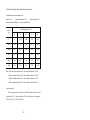
2. Modified coefficient table of ambient condition power
The conditions of generator rated output:
Altitude: O m
Ambient temperature: 25"C
Relative humidity: 30%
Ambient modified coefficient: C (Relative humidity 30%)
Altitude
(m)
Ambient temperature ("C)
25
30
35
40
45
0
1
0.98
0.96
0.93
0.90
500
0.93
0.91
0.89
0.87
0.84
1000
0.87
0.85
0.82
0.80
0.78
2000
0.75
0.73
0.71
0.69
0.66
3000
0.64
0.62
0.6
0.58
0.56
4000
0.54
0.52
0.5
0.48
0.46
Note: When the relative humidity is 60%, the modified coefficient is C-0.01
When the relative humidity is 80%, the modified coefficient is C-0.02
When the relative humidity is 90%, the modified coefficient is C-0.03
When the relative humidity is 100%, the modified coefficient is C-0.04
Counting example:
When the rated power of generator is P.=5KW, altitude is 1000m, ambient
temperature is 35'C , relative humidity is 80%, the rated power of generator is:
P=P. X (C-0.02) = 5 X (0.82-0.02) = 4KW
-28-