1
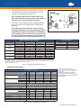
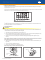
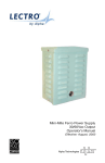
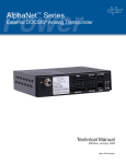
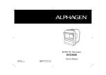
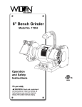
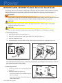
Power DCX3000 3.0kW, 36/48VDC Portable Generator Quick Guide The following instructions are intended to supplement the DCX3000 Operator’s Manual. Read and adhere to all safety instructions listed in the Operator’s Manual (Alpha P/N 041-028-B0) and this document. If you have any questions regarding safe operation of the generator, consult the Operator’s Manual or contact Alpha Technical Support. WARNING! Do not make or break any connections between the power supply battery pack and generator while the generator is running. Turn the generator off before disconnecting any cables or equipment. CAUTION! Always check the engine oil level prior to operating the generator. Failure to do so could lead to irreparable damage to the engine. DC Voltage Selector Switch CAUTION! Only use 86 octane fuel or higher and no more than 10% Ethanol or 5% Methanol by volume. 1.0 Connecting Generator 1. Open the maintenance cover (see Figure 1-1). 2. Using the DC voltage selector switch, select either 36V or 48V (see Figure 1-1). 3. Close the maintenance cover. Fue Lev Maintenance Cover 4. Connect the power cord of the UPS to the DC output coupler, ensuring there is no gap (see Figure 1-2). DC Voltage Selector Switch DC Output Coupler Voltmeter Choke Knob ON Maintenance Cover Figure 1-1, DC Voltage Selector Switch location. No Ngap OPEN OPE OFF O Fuel Valve Lever Power Coupler CLOSED Figure 1-2, Connecting the UPS to the DC Output Coupler. Note: WhenDCthe UPSCoupler battery string is connected to the generator, the backlight in the Voltmeter is turned on Output and indicates DC Voltage the battery string voltage. Selector Switch Voltmeter 2.0 Operating Generator 1. Turn the Fuel Valve Lever to the ON position (see Figure 2-1). 2. Adjust Choke Knob (see Figure 2-1). – Knob in the OPEN position to restart a warm engine. 041-028-B1-001 Rev. B (09/2012) DC Output Coupler Starter Grip O F F ON ON No gap – Pull the Choke Knob to the CLOSED position to Power start a cold engine. Coupler Maintenance LeaveCover the Choke Choke Knob Fuel Valve Lever Engine OFF O OPEN OPE N Direction to pull CLOSED Switch Figure 2-1, Fuel Valve Lever and Choke Knob operation. 1 Fuel Valve Lever Maintenance Cover CLOSED Total Power Solutions DC Output Coupler 3. Turn the Engine Switch to the ON position (see Figure 2-2). Voltmeter 4. Pull the Starter Grip until you feel resistance, then pull strongly in a straight line (see Figure 2-2). Starter Grip Note: Pulling the Starter Grip at sharp angle to the engine will prematurely wear out the cord. Do NOT let the starter grip snap back against the engine. O FF ON No gap Direction to pull 5. If the choke was CLOSED to start the engine, gradually Powerin to the OPEN position as the engine push the choke warms up. Coupler Engine Switch Note: When the engine starts, DC output will begin charging the UPS battery string automatically and the output indicator (green) will go ON. If the UPS battery string voltage is too low, the DC output will turn off. At this time, the output indicator (green) will go OFF and the overload indicator (red) will go ON (see Table 2-1). Figure 2-2, Engine Switch and Starter Grip operation. Choke Knob Battery Voltage Alarm Indicators Battery Voltage 0V to 2V 2V to 27V 27V to 42V 42V to 55V >56V 1 Voltage Select Switch Position 36V 48V 36V 48V 36V 48V 36V 48V 36V Output Indicator (Green LED) OFF OFF OFF OFF ON OFF OFF ON OFF 48V OFF Run Time Table Overload Alarm (Red LED) Forced Output 2 OFF OFF FLASHING FLASHING OFF FLASHING FLASHING OFF FLASHING Not Available Not Available ENABLED ENABLED Not Available OPEN ENABLED Not Available Not Available Not Available3 FLASHING Not Available3 Load Run Time (Hours) 25% 80% 100% 20 10 7.2 Table 2-2, Load to approximate run time. (1)–All battery voltage measurements Choke are ± 1V. (2)–To enable forced output when the Overload Alarm LED is flashing, press the output button for at least 5 seconds. The Overload Alarm Knob LED stops flashing. Release the output button, and then press it again for at least five seconds. The Output Indicator LED turns on steady, and power output begins. The operator may then release the output button. (3)–Engine shuts down after 1 second. Table 2-1, Battery Voltage alarm indicators. 3.0 Maintenance Schedule MAINTENANCE SCHEDULE REGULAR SERVICE PERIOD Note: Perform at every indicated month or operating hour interval, whichever comes first. Engine Oil Check Level CLOSED Each use OP P EEN Check Clean Every 3 months or 50 hrs. Every 6 months or 100 hrs. O O O O2 O1 Replace Canister Check Every 2 years (Replace if necessary)3 Purge tube Check Every 2 years (Replace if necessary)3 Charge tube Check Every 2 years (Replace if necessary)3 Sediment Cup Check O Spark Plug Check-adjust O Replace Spark Arrester Clean Valve Clearance Check-adjust Combustion chamber Clean Fuel tank and filter Clean Fuel tube Check Every year or 300 hrs. O Change Air Cleaner First month or 20 hrs. (1)–Replace the paper air filter element only. (2)–Service more frequently when used in dusty areas. (3)–These items should be serviced by an authorized AlphaGen dealer. For commercial use, log hours of operation to determine proper maintenance intervals. Failure to follow this maintenance schedule could result in nonwarrantable damage. O O O3 O3 Every 2 years (Replace if necessary)2 Table 2-3, Battery Voltage alarm indicators. 2 041-028-B1-001 Rev. B (09/2012) Total Power Solutions Upper Limit 4.0 Engine Oil Recommendations Oil affects performance and service life for the engine. Always use 4-stroke automotive detergent oil. The engine can hold .58 U.S. qt (.55 L) of oil. SAE 10W-30 is recommended for general use. Other viscosities shown in the chart may be used when the average temperature in your area is with the recommended range (see Figure 4-1). AMBIENT TEMPERATURE Figure 4-1, Oil recommendations for ambient temperature. The SAE oil viscosity and service category are in the API label on the oil container. We recommend that you use API SERVICE category SJ or later (or equivalent) oil. 5.0 Changing Engine Oil CAUTION! Hot engine oil can BURN. The engine should be warm to the touch but not hot when changing the oil. Draining warm oil assists rapid and complete draining. Drain Screw 1. Open and remove the oil maintenance cover (see Figure 5-1). 2. Place a suitable container below the engine to catch the used oil, then remove the oil filler cap/dipstick. Using a 10mm wrench remove the drain plug and sealing washer (see Figure 5-1). Oil Drain Plug 3. Allow the used oil to drain completely, then reinstall the drain plug and sealing washer. Tighten the plug securely. Note: Improper disposal of engine oil can be harmful to the environment and may violate local and federal laws. Dispose of the used oil in accordance with all local, state and federal laws. Oil Maintenance Cover 4. With the generator in a level position, fill to the outer edge of the oil filter hole with the recommended oil (see Oil Filler Cap Figure 5-2). Dipstick 5. Screw in the oil filler cap/dipstick securely. 6. Reinstall, close, and latch the oil maintenance cover. Note: Always wash your hands after handling motor oil. Oil Drain Plug Upper Limit Oil Maintenance Cover Oil Filler Cap Figure 5-1, Draining oil. 041-028-B1-001 Rev. B (09/2012) Dipstick Figure 5-2, Filling oil limit. 3 Total Power Solutions Filter Sediment Cup 6.0 Draining Fuel Tank and Carburetor O-Ring (replace) WARNING! Gasoline is highly flammable and explosive. You can be burned or otherwise seriously Sediment Cup injured improperly handling fuel. STOP the engine and let it fully cool before adding or draining fuel. Remove all sources of ignition, heat, and spark from the immediate area. Wipe up spills immediately. 1. Open the maintenance cover. 2. Place a suitable gasoline conatiner below the carburetor drain hose. 3. Loosen the carburetor drain screw and drain the gasoline from the carburetor (see Figure 6-1). 4. After all the fuel has drained into the container, tighten the drain screw securely. 5. Place an approved gasoline container below the sediment cup, and use a funnel to avoid spilling fuel (see Figure 6-2). Note: The engine fuel tank can hold 3.5 U.S. gallons (13.3L) of fuel. Drain Screw Figure 6-1, Draining carburetor. 6. Remove the sediment cup, then move the Fuel Valve Lever to the ON position. 7. Allow the fuel to drain completely, then reinstall the sediment cup. Filter Sediment Cup O-Ring (replace) 8. Close the maintenance cover. Sediment Cup Figure 6-2, Draining/cleaning sediment cup. 7.0 Storing Generator Proper storage preparation will help prevent corrosion damage and help extend the life of the fuel system. Prior to storage clean the generator entirely with a damp rag. Once dry, touch up damaged paint and lightly coat exposed metal surfaces with a quality rust inhibitor. To prevent fuel oxidizing, entirely drain the fuel system. If this is not possible, fill the fuel tank entirely to reduce the air in the tank (air hastens fuel oxidation) and ensure a quality gasoline stabilizer is used per the manufacturer's recommendations. It is also good practice to change the oil before long term storage. Drain Screw Alpha Technologies Inc. 3767 Alpha Way Bellingham WA 98226 USA Tel: +1 360 647 2360 Fax: +1 360 671 4936 Alpha Technologies Alpha Technologies Ltd. 7700 Riverfront Gate Burnaby BC V5J 5M4 Canada Tel: +1 604 436 5900 Fax: +1 604 436 1233 Alpha Technologies Europe Ltd. Twyford House, Thorley Bishop’s Stortford, Hertfordshire CM22 7PA United Kingdom Tel: +44 1279 501110 Fax: +44 1279 659870 Alpha Technologies GmbH Hansastrasse 8 D 91126 Schwabach Germany Tel: +49 9122 79889 0 Fax: +49 9122 79889 21 Alpha reserves the right to change specifications without notice. © 2012 Alpha Technologies Inc. All Rights Reserved. Alpha is a registered trademark of Alpha Technologies. AlphaTec Ltd. 339 Saint Andrews Street Suite 101 Andrea Chambers 3307 Limassol Cyprus Tel: +357 25 375675 Fax: +357 25 359595 AlphaTEK ooo Khokhlovskiy Pereulok 16 Stroenie 1 Office 403 109028 Moscow Russia Tel: +7 495 916 1854 Fax: +7 495 916 1349 Alpha Technologies Suite 1903, 19/F., Tower 1 33 Canton Road, Tsim Sha Tsui China Hong Kong City, Kowloon Hong Kong Tel: +852 2736 8663 Fax: +852 2199 7988 member of The 041-028-B1-001 Rev B. (09/2012) GroupTM For more information visit www.alpha.com