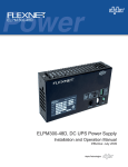
1
P/N 745-419-25-001
Alpha XP-EDH4 Transponder
Field Installation Instructions
Effective: September 2009
Alpha Technologies
AlphaNet™ Series External DOCSIS Transponder
Model XP-EDH4
745-419-C4-001, Rev. A (09/2009)
Contents
1.0 Overview to the field installation instructions.................................................................. 3
2.0 Communications Card settings...................................................................................... 3
3.0 Connection Instructions.................................................................................................. 4
3.3 XM Series 2 Power Supply............................................................................................. 5
3.4 ZTT and ZTT+ Power Supplies..................................................................................... 6
3.5 Generic Model Power Supplies...................................................................................... 7
4.0 Verifying Installation and Network Connectivity (applies to all power supplies)............. 8
4.1 LED Indications......................................................................................................... 8
4.2 Locally via a Web browser........................................................................................ 9
4.3 Remote via HTTP................................................................................................... 10
4.4 Remote via SNMP.................................................................................................. 10
Contacting Alpha Technologies: www.alpha.com
For general product information and customer service (7 AM to 5 PM, Pacific Time), call
1-800-863-3930,
For complete technical support, call
1-800-863-3364
7 AM to 5 PM, Pacific Time or 24/7 emergency support
DOCSIS® is a Registered Trademark of CableLabs.
1.0
Overview to the Field Installation Instructions
The EDH4 transponder provides the ability to manage network power through an existing cable modem infrastructure,
for a variety of power supplies as shown in this document.
The steps comprising the installation procedure are as follows:
1. Setting the jumpers and switches in their respective communications cards [Section 2.0]
2. Connecting the transponder to its respective power supply and system equipment [Section 3.0]
3. Verifying Installation and network connectivity [Section 4.0]
Save these instructions for future reference.
Installation Notes:
• Before field installation, the transponder's MAC address should be loaded into the CMTS, and DOCSIS
configuration file options should be set.
• Use a surge protector in the cabinet when the transformer is used to measure line voltage.
• Do not place the transponder on top of the power supply or batteries.
• Make all battery harness connections and connect the interface cable to the power supply before connecting the
cables to the transponder.
CAUTION!
When the EDH4 replaces an existing EDH2 or EDH3 Transponder, do not plug the AUX PWR cable into the
connector labeled CNTL. Although these connectors are identical in shape, the functionality between them is
different. The CNTL connection provides power for the Battery heater mat. System damage will occur if the
AUX PWR cable is plugged into the CNTL connector. Contact Alpha Technologies regarding the disposition of
the existing AUX PWR cable.
2.0
Communications Card settings
Verify the switches and jumpers on the respective communications cards are set as indicated in the tables below.
NOTE:
Alpha AM power supplies with RPM interface cards marked 700-019-28, 700-019-31 and 700-019-40 are
compatible with the DOCSIS HMS Analog Transponder.
XM - USM
XM2 - USM2
XM2 - USM2.5
P1 = 2 & 3
SW1-1, 2, 6, 8 = On
SW1-1, 2, 6 = On
P2, P4, P5, P6 = Closed
SW2-1, 3, 4 = On
P3 = Open
JP1 = C & 1
P7 = 5V
JP2 = 1 & 2
P8, P9, P13 = 1 & 2
P14 = N/A
SW4 = 0
Table 1, XM-USM switch settings
Table 2, XM2-USM2 switch settings
Table 3, XM2-USM2.5 switch settings
NOTE:
Output Current switch settings are determined by the output current capability of the power supply and must be
configured accordingly. Refer to your power supply user manual for setting details.
Typical Iout settings for the following communications cards:
• USM:
N/A
• USM2:
SW1-3 = Output #1, SW1-4 = Output #2
• USM2.5: SW1-3 = Output Current Scaling, 15A or 22A
• RPM:
745-419-C4-001 Rev. A (09/2009)
No switch setting required
3
3.0
Connection Instructions
NOTE:
A chipset upgrade may be required; contact Alpha for more information.
Set the jumpers and calibrate the USM card before making connections and applying the load.
3.1 AM Series Power Supply Connection
3.2 XM Series Power Supply Connection
1.Switch Battery Breaker OFF prior to removing the Inverter
Module for USM Card installation and configuration.
1.Switch Battery Breaker OFF.
2.It is advisable to install the Battery cable (providing power
to the External DOCSIS unit) and waiting until the ONLINE
LED is on steady before installing the power supply. This
will reduce the chances of the power supply transferring to
inverter due to a low signal reference on the test control pin.
3.Connect the transponder to the system as shown in figure 3.
Tamper switch
connection point
Pin 1
Pin 1
Tamper switch
connection point
Figure 2, 13-pin connector on XM Series power supply
Figure 1, 13-pin connector on AM Series power supply
When connecting to an AM Series power supply, plug the 13-pin
connector so the black wire is in pin1 and two open pins are left at
the left for tamper switch connection (as viewed from the front of the
unit).
When connecting to an XM Series power supply, plug the 13-pin
connector so the black wire is in pin1 and two open pins are left at the
bottom for tamper switch connection (as viewed from the front of the unit).
2
Legend
1
RF Cable
2, 3
Battery Sense Wire Kit for:
3
1
36V single string, 6', Alpha p/n 874-842-21
36V single string, 9', Alpha p/n 874-842-27
36V dual string, 6', Alpha p/n 874-842-20
9
36V dual string, 9', Alpha p/n 874-842-28
48V single string, 6', Alpha p/n 874-841-21
48V single string, 9' Alpha p/n 874-841-25
48V dual string, 6', Alpha p/n 874-841-20
10
48V dual string, 9', Alpha p/n 874-841-24
XM Series 2 Power Supply
Interface Cable
Alpha p/n 875-335-20 (USM2/2.5)
XM Series Power Supply
Interface Cable
Alpha p/n: 875-335-21 (USM)
AM Series Power Supply
Interface Cable
Alpha p/n: 875-335-21 (RPM)
5
Battery Heater Mat Control Cable
Alpha p/n 875-627-20
6
Ethernet Cable (optional)
Customer supplied
7
RTS Cable (optional)
Alpha p/n 745-178-21
8
Vin Sense (optional)
Alpha p/n 875-493-21
9
Surge Protector Ground Block
Alpha p/n 162-028-10
10
Plug-in Lightning Arrestor w/pass thru
(130V) l-G, l-n, N-G
Alpha p/n 162-046-10
4
4
4
7
8
5
6
7
Figure 3, Connecting the transponder to the system
745-419-C4-001 Rev. A (09/2009)
3.0
Connection Instructions, continued
3.3 XM Series 2 Power Supply
WARNING!
The XM2 batteries are isolated from chassis ground by design. Any voltage potential difference between battery
(-) and chassis ground must be eliminated before installing the transponder to avoid potential transponder
damage. To accomplish this, attach a ground jumper between battery (-) and chassis ground before installing the
transponder. Once the transponder is installed the jumper may be removed if desired.
Switch Battery Breaker OFF prior to removing the Inverter Module for USM2/USM2.5 Card installation and
configuration.
Tamper switch
connector
XM Series 2 Power Supply Connection NOTE:
When connecting to an XM Series 2 power supply, plug the 13-pin
connector so the black wire is in pin1 and two open pins are left at
the top for tamper switch connection.
Pin 1
2
Legend
1
RF Cable
2, 3
Battery Sense Wire Kit for:
3
1
36V single string, 6', Alpha p/n 874-842-21
36V single string, 9', Alpha p/n 874-842-27
36V dual string, 6', Alpha p/n 874-842-20
9
36V dual string, 9', Alpha p/n 874-842-28
48V single string, 6', Alpha p/n 874-841-21
48V single string, 9' Alpha p/n 874-841-25
10
48V dual string, 6', Alpha p/n 874-841-20
48V dual string, 9', Alpha p/n 874-841-24
XM Series 2 Power Supply
Interface Cable
Alpha p/n 875-335-20 (USM2/2.5)
XM Series Power Supply
Interface Cable
Alpha p/n: 875-335-21 (USM)
AM Series Power Supply
Interface Cable
Alpha p/n: 875-335-21 (RPM)
5
Battery Heater Mat Control Cable
Alpha p/n 875-627-20
6
Ethernet Cable (optional)
Customer supplied
7
RTS Cable (optional)
Alpha p/n 745-178-21
8
Vin Sense (optional)
Alpha p/n 875-493-21
9
Surge Protector Ground Block
Alpha p/n 162-028-10
10
Plug-in Lightning Arrestor w/pass thru
(130V) l-G, l-n, N-G
Alpha p/n 162-046-10
4
745-419-C4-001 Rev. A (09/2009)
4
8
5
6
7
Figure 4, Connections between the transponder and the system
5
3.0
Connection Instructions, continued
3.4 ZTT and ZTT+ Power Supplies
CAUTION!
Installation of the Vout and Iout sense harness requires powering down the power supply. Use an alternate source
of power during this procedure.
ZTT/+
7
10
12
8
SPI
2
11
1
4
3
9
5
Legend
1
6
Figure 5, Connections between the transponder and the system
RF Cable
2
Power Supply Interface
Alpha P/N: 875-335-22 (ZTT and ZTT+ Post 1998)
Alpha P/N: 875-335-23 (ZTT+ Pre 1998)
3,4
Battery Sense Wire Kit for:
36V single string, 6', Alpha p/n 874-842-21
36V single string, 9', Alpha p/n 874-842-27
36V dual string, 6', Alpha p/n 874-842-20
8
Vin Sense (optional)
Alpha p/n 875-493-21
9
Surge Protector Ground Block
Alpha p/n 162-028-10
10
Vout Iout Sense Harness
Alpha p/n 875-456-10
11
Tamper Wire Kit
Enclosure-specific
12
Plug-in Lightning Arrestor w/pass thru
(130V) l-G, l-n, N-G
Alpha p/n 162-046-10
36V dual string, 9', Alpha p/n 874-842-28
48V single string, 6', Alpha p/n 874-841-21
48V single string, 9' Alpha p/n 874-841-25
48V dual string, 6', Alpha p/n 874-841-20
48V dual string, 9', Alpha p/n 874-841-24
6
5
Battery Heater Mat Control cable
Alpha p/n 875-627-20
6
Ethernet Cable
Customer-supplied
7
RTS Cable (optional)
Alpha p/n 745-178-21
745-419-C4-001 Rev. A (09/2009)
3.0
Connection Instructions, continued
3.5 Generic Model Power Supplies
CAUTION!
Installation of the Vout and Iout sense harness requires powering down the power supply. Use an alternate
source of power during this procedure.
7
10
12
8
2
SPI
11
1
4
3
9
5
6
Figure 6, Connections between the transponder and the system
Legend
1
RF Cable
2
Power Supply Interface
3,4
Battery Sense Wire Kit for:
8
Vin Sense (optional)
Alpha p/n 875-493-21
Alpha p/n: 875-335-25
9
Surge Protector Ground Block
Alpha p/n 162-028-10
36V single string, 6', Alpha p/n 874-842-21
10
Vout Iout Sense Harness
Alpha p/n 875-456-10
36V single string, 9', Alpha p/n 874-842-27
11
Tamper Wire Kit
Enclosure-specific
12
Plug-in Lightning Arrestor w/pass thru
(130V) l-G, l-n, N-G
Alpha p/n 162-046-10
36V dual string, 6', Alpha p/n 874-842-20
36V dual string, 9', Alpha p/n 874-842-28
48V single string, 6', Alpha p/n 874-841-21
48V single string, 9' Alpha p/n 874-841-25
48V dual string, 6', Alpha p/n 874-841-20
48V dual string, 9', Alpha p/n 874-841-24
5
Battery Heater Mat Control cable
Alpha p/n 875-627-20
6
Ethernet Cable
Customer-supplied
7
RTS Cable (optional)
Alpha p/n 745-178-21
745-419-C4-001 Rev. A (09/2009)
7
4.0
Verifying Installation and Network Connectivity (applies to all power supplies)
After connecting the transponder, any of the three following methods may be used to verify the installation and
network connectivity.
4.1 LED Indications
The EDH4 transponder has bank of 6 green LEDs on the front panel. The state
(whether each LED is ON, OFF, or blinking) of each LED indicates its operational
functionality as indicated in the table below.
On initial power up, the LEDs will remain off for several seconds after which time
the DS, US, and Online LEDs will blink, in unison, 6 times. After this sequence
completes, the LEDs indicate the status. The PWR, DS, US, ONLINE, and
ELINK LEDs conform to the DOCSIS OSSI specification.
LED
Function
State
STAT
Debug LED:Indicates the presence or absence of data transference
between the transponder’s two processors.
ELINK
CPE Link LED:Indicates status with respect to the bridging of data to
and from a CPE device connected to the transponder’s Ethernet port
ONLINE
Online LED:Indicates status with respect to the completion of the IP
initialization process and when the unit is operational.
US
Upstream LED:Indicates status with respect to acquisition of upstream
parameters and initial ranging.
DS
Downstream LED:Indicates status with respect to downstream
scanning and synchronization.
PWR
Power LED:(Note: this LED is not tied directly to line power)
Figure 7, LED Array
Meaning
Off
Data is not being transferred between the two processors.
Blinking
Data is being transferred between the two processors.
Off
A CPE device is not connected to the transponder’s Ethernet port.
Blinking
The transponder is bridging data to/from a CPE device.
Blinking
The transponder is currently involved in the IP initialization process.
On
The transponder has completed the IP initialization process and is operational.
Blinking
The transponder is obtaining upstream parameters and is performing initial
ranging.
On
The transponder has completed a successful initial ranging sequence.
Blinking
The transponder is scanning for a downstream DOCSIS channel.
On
The transponder has locked onto and synchronized with a downstream
DOCSIS channel.
Off
The transponder is not powered or is not functioning.
On
The transponder is on.
Table 4, LED Indications of System Status
8
745-419-C4-001 Rev. A (09/2009)
4.0
Verifying Installation and Network Connectivity (applies to all power supplies), cont'd.
4.2 Locally via a Web browser
Configuring the EDH4 transponder
Connect a computer’s network port to the transponder’s Ethernet port using a standard network cable.
Launch an Internet browser and enter 192.168.100.1 into the Address. The transponder will return the
Web page shown below. Click on “Config” to display the available power supply types, and single / Dual
IP configurations. Click on the one that matches the connected power supply and desired IP mode. Click
on “Apply,” and when prompted for a User Name and Password, enter “Tollgrade” (without the quotes) in
both places and click on “OK.”
The transponder will reset (the LEDs will go through a typical power up sequence) and begin
communicating with the power supply and the cable network.
Figure 8, Configuration Screen [selection of power supply shown]
Communication with the headend may be verified by clicking on the “Status” link, which will display key
parameters including upstream and downstream power levels, and the cable modem’s IP address, which
confirms connectivity.
Figure 9, Status Information Screen
745-419-C4-001 Rev. A (09/2009)
9
4.0
Verifying Installation and Network Connectivity (applies to all power supplies), cont'd.
4.2 Locally via a Web browser, continued
Once the transponder is online, power supply data is also available via the Web page. Click on “HMS,”
and then “PS1” to see information which confirms the battery sense harness is connected properly and
the transponder is configured for the right power supply.
Figure 9, HMS Device Data Screen
4.3 Remote via HTTP
Enter the cable modem’s network IP address into a Web browser and follow the steps in Section 4.2.
4.4 Remote via SNMP
Enter the cable modem’s network IP address into a MIB browser and use “DOCSIS” for both the get and
set community strings.
Query the power supply’s input voltage. [OID: 1.3.6.1.4.1.5591.1.4.2.1.23.1] A valid response verifies
remote SNMP communications.
10
745-419-C4-001 Rev. A (09/2009)
Power
Alpha Technologies
®
Alpha Technologies
3767 Alpha Way
Bellingham, WA 98226
USA
Tel: +1 360 647 2360
Fax: +1 360 671 4936
Web: www.alpha.com
Alpha Technologies Ltd.
4084 McConnell Court
Burnaby, BC, V5A 3N7
CANADA
Tel: +1 604 430 1476
Fax: +1 604 430 8908
Alpha Technologies
Europe Ltd.
Twyford House Thorley
Bishop's Stortford
Hertfordshire CM22 7PA
UNITED KINGDOM
Tel: +44 0 1279 501110
Fax: +44 1 279 659870
Alpha Technologies GmbH
Hansastrasse 8
D 91126 Schwabach
GERMANY
Tel: +49 9122 79889 0
Fax: +49 9122 79889 21
Alphatec, Ltd
339 St. Andrews Street
Suite 101 Andrea Chambers
3307 Limassol
CYPRUS
Tel: +357 25 375675
Fax: +357 25 359595
AlphaTEK ooo
Khokhlovskiy Pereulok 16
Stroenie 1, Office 403
109028 Moscow
RUSSIA
Tel: +7 495 916 1854
Fax: +7 495 916 1349
Alphatec Baltic
S. Konarskio Street G.49-201
Vilnius LT-03123
LITHUANIA
Tel: +370 5 210 5291
Fax: +370 5 210 5292
Alpha Technologies
34, Grande Rue
Bétheny, F-51450
France
Phone: +33 32 64990 54
Fax: +33 67 54289 44
Due to continuing product improvements, Alpha reserves the right to change specifications without notice.
Copyright © 2009 Alpha Technologies, Inc. All rights reserved. Alpha is a registered trademark of Alpha Technologies. 745-419-C4-001, Rev. A.