1
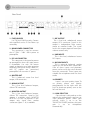
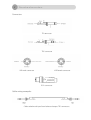
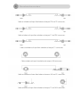
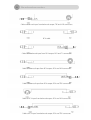
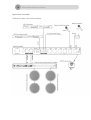
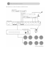
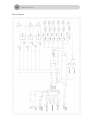
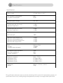
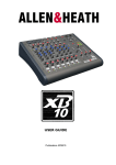
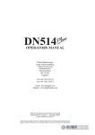
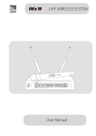
IMPORTANT SAFETY INSTRUCTIONS
When using this electronic device, basic precautions should always be taken, including the
following:
1. Read all instructions before using the product.
2. Do not use this product near water (e.g., near a bathtub, washbowl, kitchen sink, in a wet
basement or near a swimming pool etc).
3. Use this device when you are sure that preamplifier has a stable base and it is fixed securely.
4. This product, in combination with amplifier and loudspeakers may be capable of producing
sound levels that could cause permanent hearing loss. Do not operate for a long period of
time at a high volume level or at a level that is uncomfortable. If you experience any
hearing loss or ringing in the ears, you should consult with otorhinolaryngologists. The
product should be positioned so that proper ventilation is maintained.
5. The product should be located away from heat sources such as radiators, heat vents, or
other devices (including amplifiers) that produce heat.
6. The product should be connected to a power supply that is described in the operating
instructions or are marked on the product. Replace the fuse only with one of the specified
type, size and correct rating.
7. The power supply cord should be undamaged and never share an outlet or extension cord
with other devices so that the outlet or extension cord's power rating is exceeded. Never
leave device plugged be left plugged in to the outlet when it’s not being used for a long
period of time.
8. Care should be taken so that objects do not fall into, and liquids would not be spilled
through, the enclosure's openings.
9. The product should be serviced by qualified service personnel if:
•
•
•
•
The power supply cord or the plug has been damaged.
Objects have fallen into or liquid has been spilled on the product.
The product has been exposed to rain.
The product has been dropped or the enclosure damaged.
All the other servicing must be referred to qualified service personnel too.
10. Unplug this device when unused for long periods of time.
11. There are some areas with high voltage inside, to reduce the risk of electric shock do not remove
cover of the preamplifier. The cover should be removed by the qualified personnel only. No user
serviceable parts inside.
CONTENTS:
Before you start
What's in the box
Features
Hints on installation
4
4
4
Controls and connections
Front panel
Rear panel
Connectors
Cable wiring examples
Application example
5
6
7
7
10
Specifications
Block diagram
Specifications
12
13
Congratulations on your choice of an iMIX 63 preamplifier. iMIX 63 is a professional mixer
preamplifier, with built-in six balanced combo inputs and three stereo RCA inputs. Input gain selector for
the balanced combo inputs, phantom power, signal and output level indication, balanced stereo output
and 24V power supply are collected in to this device, to make iMIX 63 more flexible and easy adapted to
various of installations. Please read this manual carefully to get the most important information about your
new unit. Thank you for selecting iMIX 63.
What’s in the box?
Items those are included in the box:
•
•
•
Preamplifier iMIX 63
Instruction manual
Power cable
Features
• Six COMBO inputs with selectable gain, Line
or Mic. Three stereo RCA inputs.
•
DC 24V input for external power supply.
Screw terminal.
• Phantom power. Switchable on each combo
inputs separately.
•
Signal and four LED bar for signal level
indication in the output.
• Priority input.
•
3 Band: low, mid and high equalizer.
Hints on Installation
This user manual contains an important information on operating iMIX63 preamplifier correctly and safety.
Please read it carefully before operating your preamplifier.
Before connecting microphones or instruments, make sure that the power of all your systems
components including the preamplifier is turned off. Also, make sure that all of inputs controls of your
preamplifier are turned down. This will avoid damage to your speakers and avoid unexpected noise. Before
disconnecting the iMIX63 always turn off the power switch.
Front Panel
1. INDICATION
These green LEDs indicate audio signal in
the input.
2. VOLUME COMBO XLR
These rotary knobs are for adjusting
volume level of the universal mono inputs.
First six inputs can be use as balanced line
level as well as microphone level inputs. The
phantom power can be activated for these
inputs separately in rear panel. The input
gain selector is located in the rear panel too.
3. VOLUME STEREO RCA
These rotary knobs are for adjusting
volume level of the line level RCA inputs.
Input 7, 8 and 9 are line level, unbalanced,
stereo inputs.
4. MONITOR
This is volume control for adjusting audio
level in the balanced monitor output. In this
output can be linked audio from the combo
inputs.
5. MONITOR ON/OFF BUTTON
If this button is in the “ON” position, all
combo inputs are linked in to monitor
output. At this moment only input 7, 8 and 9
are available in the master, mono and rec.
outputs. When the button is off, all inputs
are linked in to main, mono and rec. output,
at this moment monitor output is inactive.
6. EQUALIZER
3 band: low, mid and high equalizer.
Center frequency of the “LOW” tones
equalizer is 80Hz, adjusting level ±15dB. The
“MID” tones can by adjusted in ±12dB range.
Center frequency 2.5kHz. “HI” tones are ready
to be adjusted in ±15dB range. Center
frequency – 12kHz.
7. MONO
This volume control is designed to adjust
volume level in the balanced mono output. If
monitor button is “ON”, in this output are
available audio from stereo RCA inputs only.
8. LED BAR INDICATOR
This is level indicator of the master output.
9. MASTER
This potentiometer is designed to adjust
audio level in the master output.
10. “POWER ON” INDICATOR
This LED indicates status of the power.
This LED indicates when preamplifier is
turned on.
11. POWER BUTTON
This button is designed to turn on/off
main power of the device.
Rear Panel
1. FUSE HOLDER
Use T315mA 250V fuse only. Contact
with qualified service if fuse blows up
constantly.
2. MAIN POWER CONNECTOR
The connector is used to connect
the AC 220V – 240V ~50Hz power to
preamplifier.
3. DC 24V CONECTOR
This connector is designed to power
up preamplifier when the main power
is unavailable. Use only 24V power
supply or batteries and take attention
to polarity during the wiring. If both, AC
and DC power are connected;
preamplifier will use main AC power.
4. MASTER OUT
This is balanced, stereo line level
output, XLR connectors.
5. MONO OUTPUT
This is line level, balanced output,
6.3mm TRS connector.
6. MONITOR OUTPUT
This is line level, balanced output,
6.3mm TRS connector. Signal in this
output is available when MONITOR
BUTTON is in the ON position. In this
output only signal from combo
connectors (input 1 - 6 ) is available.
7. REC OUTPUT
This is line level, unbalanced stereo
output, RCA connector. Signal in this
output is independent from master,
mono or monitor knobs. The signal
level in this output depends from input
volume controls only.
8. LINE INPUTS
This is line level, unbalanced stereo
RCA inputs.
9. MIC/LINE INPUTS
This is universal, balanced combo
inputs for XLR and 6.3mm connectors.
Gain of these inputs and phantom
power can be set by the switch located
near the connectors. These inputs are
suitable for microphone and line level
audio.
10. PRIORITY
Input 1 can set as priority input. To
set priority, please turn priority
potentiometer to the right until the
end. To deactivate priority turn to the
left until the end.
11. GAIN SELECTOR
Gain selector is designed to set the
gain of the combo inputs and turn on
+20V phantom power. When gain
selector switch is set in to the
“PHANTOM POWER” position, the input
gain
is
set
to
microphone
automatically.
Connectors
TR connector
TRS connector
XLR male connector
XLR female connector
RCA connector
Cable wiring examples
Cable to balanced input from balanced output. TRS connectors.
Cable to unbalanced input from balanced output. TRS and TS connectors.
Cable to balanced input from unbalanced output. TS and TRS connectors.
Cable to unbalanced input from unbalanced output. TS connectors.
Cable to balanced input from balanced output. XLR connectors.
Cable to unbalanced input from balanced output. XLR and TS connectors.
Cable to balanced input from unbalanced output. TS and XLR connectors.
Cable to balanced input from balanced output. TRS and XLR connectors.
RCA cable.
Cable to unbalanced input from RCA output. RCA and TS connectors.
Cable to balanced input from RCA output. RCA and XLR connectors.
Cable to balanced input from RCA output. RCA and TRS connectors.
Cable to RCA input from balanced output. RCA and XLR connectors.
Cable to RCA input from balanced output. RCA and TRS connectors.
Application example
Conferences room with audio recording:
Background music station with paging microphone priority:
Block diagram
Specifications
Power supply
AC 230V, 50Hz or 24V DC
DC 24V power consumption
AC power consumption
9,6W
10,5W
Phantom power voltage
18V - 20V
Combo input gain (line level)
Maximum input level
-12dBu
+12dBu
Combo input gain (Mic level)
Maximum input level
-52dBu
-15dBu
RCA input gain
-4dBu
Maximum MAIN output level
Maximum MONO output level
Maximum MONITOR output level
Maximum REC output level
+16dBu
+27dBu
+27dBu
+21dBu
THD
SN ratio
Crosstalk (input to output)
0.03% (@ 1kHz)
>103dBu
-82dBu
Microphone input impedance
Line input impedance
Output impedance
1,4kΩ
10kΩ
120Ω
Frequency response
Equalization (low)
Equalization (mid)
Equalization (High)
20 Hz – 22 kHz
±15 dBu @ 80Hz
±12 dBu @ 2,5kHz
±15 dBu @ 12kHz
Dimensions
Weight
483mm x 195 mm x 44 mm
2.9 kg
The specifications above are correct at the time of printing of this manual. For improvement purposes, all
specifications for this unit, including design and appearance, are subject to change without prior notice.
NOTES:
______________________________________________________________
______________________________________________________________
______________________________________________________________
______________________________________________________________
______________________________________________________________
______________________________________________________________
______________________________________________________________
______________________________________________________________
______________________________________________________________
______________________________________________________________
______________________________________________________________
______________________________________________________________
______________________________________________________________
______________________________________________________________
______________________________________________________________
______________________________________________________________
______________________________________________________________
______________________________________________________________
______________________________________________________________
______________________________________________________________
______________________________________________________________
______________________________________________________________
______________________________________________________________
______________________________________________________________
______________________________________________________________
______________________________________________________________
______________________________________________________________
______________________________________________________________
______________________________________________________________
______________________________________________________________
______________________________________________________________
______________________________________________________________
______________________________________________________________
______________________________________________________________
______________________________________________________________
______________________________________________________________
______________________________________________________________
AMC is a registered trademark of AMC Baltic www.amcpro.eu