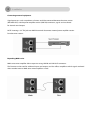
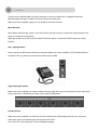
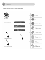
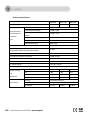
1
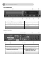
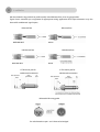
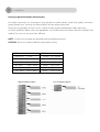
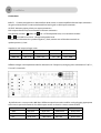
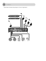
CONTENTS:
Before you start
Precautions
Before you start
3
5
Controls and connections
Front panel
Rear panel
6
6
Installation
Rack mounting
Wire connectors
7
8
Connections
Adjusting amplifier
10
14
Specifications
Block diagram
Technical data
17
18
Security Precautions
◎ Carefully READ instructions before use.
◎ Amplifiers can be operated on either 115 V or 230 V (50-60Hz), which can be selected by changing switch
position on the rear panel. The amplifier is factory set to 230 VAC mains voltage.
◎ Keep this user manual nearby for any reference.
Precaution points and notices
Below-described precaution points and notices are to prevent self injury and property damage. Before
operating the amplifier, read this manual first to get known of potential safety hazard and to understand the
meaning of the precaution points and notices.
DO NOT install or mount the amplifier on unstable objects, such as on the rickety table or the slanted
surface. It may result in the amplifier to fall and cause body injury and/or property damage.
Be sure to ground to the safety ground (earth) terminal to avoid electric shock. Never ground to a gas pipe.
Use the amplifier only with appropriate voltage specified on the amplifier. Using the voltage higher than
specified may cause fire or electric shock.
DO NOT cut, twist, damage, nor modify the power supply cord. In addition, avoid using the power cord
close to heaters and don’t place heavy object, including the amplifier itself, on the power cord, as it may
cause fire or electric shock.
DO NOT expose the amplifier to rain or the environment where water or other liquids may be splashed,
doing this, it may cause fire or electric shock.
DO NOT remove nor plug in the power supply with wet hands, for it may cause electric shock.
Be sure to grasp the power supply plug when unplugging. DO NOT pull on the cord itself. Operating the
amplifier with damaged power supply cord may cause fire or electric shock.
Avoid installing the amplifier in humid or dusty places, the area exposed to the direct sunlight, locations
generating smoke or steam, or the spot near the heaters. It may result in fire or electric shock.
When moving the amplifier, be sure to remove its power supply cord from the wall outlet. Moving the
amplifier with the power cord connected to the outlet may cause damage to the power cord and resulting
in fire or electric shock. When removing the power cord, be sure to grasp its plug to pull.
DO NOT block the ventilation slots of the amplifier chassis. It will cause the temperature rising and may
result fire.
■
AC Power Source. The supply transformer has been designed for use on either 115V or 230V,
(50-60Hz), selected by a push switch on the rear panel. The amplifier is factory set to 230V mains
voltage.
When using the Amplifier
When following irregular situations are found while using amplifier, immediately switch off the power,
disconnect the power supply plug from the AC outlet. Don’t try to operate the amplifier again until
inspected by local dealer. Contact your local dealer to check the amplifier.
The amplifier falls.
Amplifier is malfunction.
Water or any metallic object gets into the amplifier.
The smoke or strange smell coming from the amplifier.
The power supply cord is damaged, such as exposure of the core, disconnection etc.
DO NOT put cups, bowls or other containers with liquid or metallic object in it on the top of the
amplifier. If accidentally spilled onto the amplifier, it may result fire or electric shock.
DO NOT touch the power supply plug during thundering and lightning, for it may result electric
shock.
DO NOT insert or drop the metallic objects or flammable materials into the ventilation slots of the
amplifier, for it may result fire or electric shock.
DO NOT open nor remove the amplifier cover to prevent fire or electric shock, for there are high
voltage components inside.
Make sure that the volume control is turned to minimum position before power is switched on. Loud
sound produced at high volume when power is switched on may damage hearing.
DO NOT place heavy objects on the amplifier, for it may cause it fall and may result in body injury
and/or property damage. Besides, the object itself may cause damage or body injury.
DO NOT operate the amplifier for the extended period of time when sound distortion is heard. It is an
indication of malfunction, which may cause heat and result fire.
Switch the power off and unplug the power supply plug from the AC outlet for safety purposes,
when cleaning or leaving the amplifier unused for 7 days or more. Fire or electric shock may occur.
If the dust accumulates on the power supply plug or on the wall AC outlet, fire may result in. Clean it
periodically. In addition, make sure the plug is inserted in the wall outlet securely.
Contact your local dealer to clean the dust, if the dust has accumulated in the amplifier for a long
period of time. Dust accumulation may result fire or damage.
Welcome
Congratulations on purchasing MMA series multi-function commercial amplifier. New MMA series amplifiers are
designed to provide a big impact in sound reproduction and to produce highest quality audio at an affordable
price. We wish you great enjoyment and satisfaction when using your amplifiers, whether you are an installation, or
reinforcement engineer.
Unpacking and Installation
Although installing and operating this amplifier is not complicated, a few minutes of your time is required to read
this manual to install this device properly and become familiar with its features and how to use them. Please pay
attention to given precautions when using or moving this device. Never place the unit near radiator, in front of
heating vents, to direct sun light. It should not be used in excessive humidity or dusty environment. Otherwise
warranty may be voided.
Connect this unit with matching system components described on the following pages.
Features
MMA 60, MMA 120 and MMA 240 are comprehensive, all-in-one mixer-amplifier solutions for commercial
and industrial applications, providing all necessary features in a single unit.
• Six microphone or line inputs offering
• 60 watts (MMA 60), 120 watts (MMA 120),
XLR and RCA jacks,
240 watts (MMA 240) rated power output,
• Adjustable input gain,
• High efficiency Class-D Amplifier (MMA 240),
• Remote microphone via phoenix connector,
• Advanced protection system includes current limiting,
• M.O.H (Music On Hold) output,
over current and thermal protection,
• Telephone paging input via phoenix connector,
• Seven band graphic equalizer,
• Assignable phantom power for Channel 1 and
• Expendable by adding audio mixer and power
Channel 2,
amplifier with LINK and PRE-AMP terminal,
• Three level priority muting,
• Low distortion and low noise level,
• Built in four type user selectable pre-announce
• Compact size and lightweight.
chime,
• ldeal for commercial and industrial use.
Front panel description
1. Bay for adding optional music source (CD player
with AM/FM Tuner, Compressed audio player).
2. Graphic equalizer controls
(125Hz/250Hz/500Hz/1kHz/2kHz/4kHz/8kHz).
3. Indicators (Protection/Output level/Power).
4. Input channel volume controls.
5. Master volume controls.
6. Pre-announce chime switch.
7. All speaker zone output selector.
8. Individual speaker zone output
selectors.
9. Power switch
Rear panel description
1. AC fuse.
7. Signal input connectors.
2. Expansion ports
(AMP-IN/PRE-AMP-OUT/LINK-IN/LINK-OUT).
3. M.O.H (Music On Hold) output and level controls.
8. Remote microphone station input
connector and output level control
9. Telephone paging input connector.
4. Pre-announce chime level control.
10. Speaker outputs connector (4 Ω,
selectable 25V, 70V and 100V ).
5. Gain controls for variable input level.
6. Phantom power and priority control switches.
11. AC power cable.
Installation
CAUTION: Before beginning make sure the power cord is disconnected from mains source, set power switch
to “OFF” position and turn all level controls counterclockwise.
When using single mixer-amplifier application leave around 12 inch (about 30 cm) of air space around the
unit for efficient convection cooling.
When stacking units in an equipment rack allow 2U rack space between units for efficient convection cooling.
There should be also left 2-inches space between unit sides and rack side walls, and 4-inches from unit rear
panel and back of the rack.
How to attach rack mount bracket:
1. Each amplifier is supplied with two rack mount brackets and six screws for attaching to the unit.
2. Place a rack mount bracket flush to the side of the unit orienting rack mounting surface to front of the unit.
3. Fix it with screwing in given screws.
4. Repeat the same operations for attaching mount bracket to the other side of device.
5. Remove the four legs from bottom of unit.
We recommend using pre-built or professionally wired balanced line, 22 to 24 gauge cables.
Figure shows connector pin assignment for appropriate wiring application. RCA input connectors may also
be used for unbalanced signal inputs.
Balanced line
Balanced line
Unbalanced line
Unbalanced line
¼” TRS mono jack for
¼” TRS mono jack for
unbalanced connection
unbalanced connection
Balanced XLR wiring guide
For unbalanced use pin 1 and 3 have to be bridged
Choosing right wire diameter and connectors
For output connector we recommend using pre-built or professionally wired high quality and heavy
gauge speaker wires. You may use Phoenix blocks for your output connectors.
To prevent the possibility of short-circuits, wrap or insulate exposed loudspeaker cable connectors.
Using the guidelines below, select the appropriate size wire based on the distance between amplifier and
speaker. The wire sizes are given for a 4 Ω load.
NOTE : Custom wiring should only be performed by qualified personnel.
CAUTION : Never use shielded cable for output power wiring
Distance
Wire size
Up to 25 ft.
(7,5 m)
16 AWG
(Ø 1,29mm)
25 - 40 ft.
(7,5 - 12 m)
14 AWG
(Ø 1,62mm)
40 - 60 ft.
(12 m - 18 m)
12AWG
(Ø 2,05 mm)
60 -100 ft.
(18 m - 30 m)
10AWG
(Ø 2,5 mm)
100 - 150 ft.
(30 m - 45 m)
8AWG
(Ø 3,2 mm)
150 - 200 ft
(45 m - 60m)
6AWG
(Ø 4,11 mm)
Figure shows connector pin assignments for wiring
High-Z Speaker Output
Low-Z Speaker Output
Connections
INPUTS:
Connect microphones or balanced line-level sources to mixer-amplifier balanced input connectors.
Set gain to desired level. Connect unbalanced line-level signals to RCA input connectors.
OUTPUT: Maintain proper polarity on output connectors.
Each output channel may be connected via Phoenix connectors.
Use terminals marked
(GND) and
for a 4 Ω loudspeaker load, or use terminals marked
to
and COM for constant - voltage loudspeaker loads.
Connect the COM terminal to speaker negative (-) lead; connect one of the other terminals to
speaker positive (+) lead.
Impedance and output voltages ratios
MMA 60
4Ω / 15.5V
10Ω / 25V
83Ω / 70V
165Ω / 100V
MMA 120
4Ω / 22V
5.2Ω / 25V
42Ω / 70V
83Ω / 100V
MMA 240
4Ω / 31V
2.6Ω / 25V
21Ω / 70V
42Ω / 100V
NOTE : The total speaker system impedances indicated in the table represent.
Different voltages and impedance could be selected to Hi-Z outputs by changing wires connected to T10, T11,
T12 and T13 terminals.
By default unit is set to provide 100V lines. Different output line modes could be set by plugging appropriate
color wires to particular terminals. Possible output modes are listed in a wire to terminal table.
Mode\Terminals
T10
T11
T12
T13
100V
RED wire
BLUE wire
GREEN wire
BLACK wire
70V
GREEN wire
RED wire
BLUE wire
BLACK wire
25V
BLUE wire
GREEN Wire
RED wire
BLACK wire
Possible speaker connection types are shown in a figure below.
CAUTION: Never use both the Low-Z(4 Ω) and Hi-Z (25V, 70V and 100V) terminals at the
same time.
Typical input and output wiring diagram is shown in a figure below.
Connecting external equipment
Signal processors such as equalizers or limiters could be connected between the mixer section
(PRE-AMP OUT) and the power amplifier section (AMP IN) connectors, signals can be tailored
for desired sound output.
NOTE: Inserting a 1/4” TRS jack into AMP IN terminal disconnects internal power amplifier section
from the mixer section.
Expanding MMA series
MMA series mixer-amplifier allows expansion using LINK IN and LINK OUT connectors.
This function can be used for additional inputs and outputs and also affects amplifier to which signals are heard
when another mixer or MMA series mixer-amplifier is wired.
Preannounce chime
MMA series mixer-amplifier supply user selectable 4 kinds of preannounce chime.
The way of set up is same as follow figure.
Above figure shows default factory setup. Pre-announce chime type could be changed by changing
jumper position on a T3.
Priority
This function allows talk over for MIC channel 1 and 2.
While this function is activated all other input signals are muted.
Figure shows the priority switches and its “ON” and “OFF” positions.
Phantom power
MMA series mixer-amplifier supply DC + 15 Volts phantom power
to use condenser microphone with MIC 1 and 2 channels.
Figure shows the phantom power switches and its “ON” and
“OFF” positions.
Connect mixer-amplifier MUSIC ON HOLD connector to music-on-hold input on telephone interface/
PBX like telephone pager. Set MUSIC ON HOLD volume to proper level.
MMA series mixer-amplifier supply two way of MUSIC ON HOLD function.
Music On Hold
When MUSIC ON HOLD dip switch is set to “INT”, MUSIC ON HOLD output is routed from optional internal CD
player or compressed audio player.
While dip switch is set to “EXT” position, MUSIC ON HOLD output is routed from LINE IN (Channel 6) input
channel.
Tele - paging function
Priority signal from PBX station could be connected to MMA series mixer-amplifier via TELE-PAGING Phoenix
connector. This way public announcement could be made via PBX.
Signal input gain control
MMA series mixer-amplifier can accept variable and wide range input signals by input level control. Input level
can be adjusted to -44dB letting to accept various external equipment.
Priority Control
MMA series mixer-amplifier has three layer priority mute functions. When higher level source is activated,
other input signals are muted except same priority level source.
CH3~CH6>CH1~CH2, Remote MIC, Chime>Telephone paging.
Example application diagram is shown in a figure below
Block diagram
Technical Specifications
Rated Output Power at THD 0.5%
Input Sensitivity
for full output at
maximum
Gain
MMA 60
MMA 120
MMA 240
60Watts
120Watts
240Watts
Balanced Microphone Channels
-50dB ± 3dB
Balanced Line Channels
-22dB ± 3dB
Balanced Remote Microphone
Station
-50dB ± 3dB
Balanced Telephone Paging
-21dB ± 3dB
Unbalanced Link-In
-17dB ± 3dB
Unbalanced Amp-In
0dB ± 3dB
Frequency Response
50Hz~15kHz
Graphic Equalizer
125Hz,250Hz,500Hz,1kHz,2kHz,4kHz,8kHz
±12dB
Signal to Noise Ratio at rated power output
Better than 90dB
Crosstalk at all control maximum
-70dB at 1kHz
Total Harmonic Distortion(THD) at 1kHz rated power
Less than 0,5%
Phantom Power
15VDC
DC Output Offset
Less than ±3mV
Operating Temperature/Humidity at non-condensing
0°~40°C at 95% humidity
Output Voltage
and
Impedance
Construction
4Ω
15.5V
22V
31V
25V
10Ω
5.2Ω
2.6Ω
70V
83Ω
42Ω
21Ω
100V
165Ω
83Ω
42Ω
Cooling
Convection Cooled
Dimensions (Width/Height/Depth)
420(W) x 88(H) x 320(D) mm
Net Weight
8.72 kg
AMC is a registered trademark of AMC Baltic www.amcpro.lt
9.76kg
10.70 kg