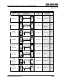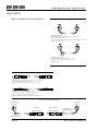
1
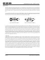
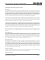
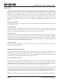
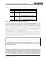
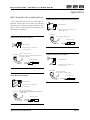
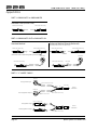
228
unidirectional
audio interface
8-CH A N N E L C O N S U M E R t o P R O L E V E L I N T ERFACE
[ - 1 0 d B V U NBALANCED IN to +4dBu BALANCED OUT]
S Y S T E M S
THE SOLUTION DELIVERY SERIES
Solution Delivery Series
228
8-channel unidirectional
audio Interface
Instruction Manual
P/N 999-4180
Revision 1 Released 01/28/2004
Manufactured by
Aphex Systems Ltd.
11068 Randall St.
Sun Valley, CA 91352
USA
S Y S T E M S
Copyright 2004 Aphex Systems Ltd. All rights reserved.
Produced by: Donn Werrbach. Creation tool: Adobe InDesign 2.0. Printed by: Stuart F. Cooper Co., Los Angeles.
228
instruction Manual
A MESSAGE FROM THE PRESIDENT
Dear Aphex customer,
Thank you for selecting the Model 228 as your interface between consumer level outputs and professional level
inputs.
By using this interface you will improve the sonic performance of your installation - setting levels for exact
balancing between different channel outputs and devices will be very quick and simple, gain structure will be
idealized for the lowest noise, and balanced lines will make your system more immune from induced noise.
Even though the Model 228 is a relatively simple design there was a great deal of research and thought that
went into its development. We trust that you will find its performance and features equal to what you have
come to expect from all Aphex products.
Very truly yours,
Marvin Caesar
Safety Declarations
CAUTION: For protection against electric shock, do not remove the cover. No user serviceable parts inside.
WARNING: This equipment has been tested and found to comply with the limits for a Class A digital device pursuant to
Part 15 of the FCC Rules. These limits are designed to provide reasonable protection against harmful interference when
the equipment is operated in a commercial environment. This equipment generates, uses, and can radiate radio frequency
energy and, if not installed and used in accordance with the operating guide, may cause interference to radio communications. Operation of this equipment in a residential area is likely to cause interference in which case the user will be required
to correct the interference at his own expense.
The user is cautioned that changes and modifications made to the equipment without approval of the manufacturer could
void the user’s authority to operate this equipment.
It is suggested that the user use only shielded and grounded cables to ensure compliance with FCC Rules.
|
Conforms to standards
UL60950 and EN60950.
®
C
US
59887
Page 2
Aphex Systems Ltd. Model 228
Copyright 2004 by Aphex Systems, LTD. All rights reserved. All Aphex products are trademarks or registered trademarks of Aphex Systems, LTD. Other brand and product names are trademarks or registered trademarks of their respective holders.
8-channel audio interface
228
Table of Contents
1.0 QUICK START - Page 4
2.0 INSTALLATION - Page 6
2.1 Mounting
2.2 Rear Panel View
2.3 AC Line Connection
2.4 Input Connectors
2.5 Output Connections
3.0 CONTROLS AND INDICATORS - Page 7
3.1 Front Panel View
3.2 Meter and Indicator Window
3.3 Meter Select Button
3.4 Interface Gain Trimmers
4.0 SPECIFICATIONS - Page 8
4.1 General Specifications
42 Architectural Specifications
5.0 WARRANTY AND SERVICE - Page 10
51 Limited Warranty
52 Service Information
6.0 APPENDICES - Page 11
Appendix A - Introduction to Balanced and Unbalanced Wiring
Appendix B - Dealing With Ground and Hum
Appendix C - Wiring Techniques
Appendix D - Standard Cable Wiring
Aphex Systems Ltd. Model 228
Page 3
228
instruction Manual
1.0 Quick Start
1. Be sure all used channels have properly made-up cables and connectors.
2. Play the audio source and check to see signal presence is indicated for all active channels.
3. While the audio source is playing, select each channel to the VU meter and verify the loudest sounds are
peaking to zero VU with maybe a few peaks hitting +3. If the reading is too high, you can trim down the gain
of the offending channel. If the level is too low, make sure the trimmer is set to the full-clockwise position for
maximum gain. If there is still not enough gain available to bring the VU indications up to 0VU, then your
source’s output level needs to be brought up by increasing its output level controls.
BALANCED OUTPUTS
UNBALANCED
INPUTS
8
7
6
5
4
3
8
7
1
2
EXPANDED VU METER AND INDICATORS
Shows the presence of signal or clipping on
each channel. The VU meter can be selected
to each channel.
POWER SWITCH
METER SELECT
Selects channels to the meter. The metering
window can be dimmed by pressing and holding this button for over 1 second. Brightness is
restored upon re-pressing the button.
Page 4
Aphex Systems Ltd. Model 228
6
228
8-channel audio interface
Quick Start
5
4
3
2
CHECK VOLTAGE
Be sure it is configured for your power mains
voltage. It is not user adjustable.
1
FUSE
Voltage and Fuse
Ratings Label
CHASSIS GROUND
Connect to local ground bus if needed to
reduce hum.
OUTPUT TRIMS
Set the gain of each interface channel: Fully
clockwise, the gain is calibrated so a -10dBV
unbalanced input produces a +4dBu balanced
output. Fully CCW, the gain is unity.
NOTE: No extra gain is provided for input
levels below -10dBV.
Aphex Systems Ltd. Model 228
Page 5
228
instruction Manual
2.0 Installation
3.1 MOUNTING
The Model 228 occupies a single rack space (45mm or 1-3/4 inches) of a standard EIA equipment rack.
When rack mounting, use appropriate cushioned rack screws. Never restrict air flow through the device’s fan
or vents. When installing the units into a rack, distribute the units evenly. Otherwise, hazardous conditions may
be created by an uneven weight distribution. Connect the unit only to a properly rated supply circuit. Reliable
earthing (grounding) of rack mounted equipment should be maintained. Try not to position the 228 directly
above devices that generate excessive heat such as power amplifiers (unless adequately ventilated) or near
equipment with heavy transformer hum fields.
3.2 REAR PANEL VIEW
BALANCED OUTPUTS
UNBALANCED
INPUTS
8
7
6
5
4
3
2
8
7
6
5
4
3
2
1
1
FUSE
3.3 AC LINE CONNECTION
Observe the label to the right of the fused receptacle indicating the nominal AC supply voltage that your 228
is built for. If your supply voltage does not agree with this rating, you will have to consult the factory or an
authorized distributor or representative about changing the line voltage of your unit.
T
WARNING: The line voltage setting is not user convertible.
3.4 INPUT CONNECTORS
The unbalanced input connectors are located on the rear panel. There is one RCA jack per channel.
3.5 OUTPUT CONNECTORS
The balanced output connectors are located on the rear panel. There is one XLR 3-pin male jack per channel.
Pin 2 of the XLR is the impedance balanced driven and is in-phase with the signal at the RCA input jack. Pin 3 is
the undriven impedance balancing pin. Wire pins 2 and 3 to the twisted pair as a standard balanced output.
See Appendix C for proper wiring diagrams that cover a miriad of different situations.
Page 6
Aphex Systems Ltd. Model 228
8-channel audio interface
228
3.0 Controls & Indicators
3.1 FRONT PANEL VIEW
3.2 METER AND INDICATOR WINDOW
The extended range VU meter follows industry standard
ASA VU meter ballistics. It indicates the average volume
level without regard to peaks. Unlike peak meters usually found on digital audio gear, the VU meter is a great
indicator of the sound’s loudness to the ear. However,
beware that this meter will never indicate the same readings as peak meters.
The presence of audio is indicated by 8 green/red (dualcolor) LED’s. The LED blinks green when signals above
-30VU are present. The LED turns red if clipping is detected in that channel. If a green indicator blinks when no
audio is running, there is probably a high noise level in that source channel. It may be wise to investigate for
wiring or equipment problems.
3.3 METER SELECT BUTTON / DIMMER
Pressing this button moves the VU meter selector through the channels. The selected
channel is indicated by one of eight green LED’s.
In certain circumstances, such as in a home theater environment, the blinking lights
and meter may become distracting. I would desirable to dim them while viewing.
This can be accomplished by holding down the meter select button for more than
one second. The lights are restored immediately by the next press of the button.
3.4 INPUT GAIN TRIMMERS
Some flexibility is afforded in matching the unbalanced input to the balanced output levels.
The range of the trimmers is 0 to -12dB. At the 0dB trim position, the interface gain is calibrated to 11.79dB. That precisely raises a -10dBV unbalanced input to a +4dBu balanced
output. For matching hotter levels, simply reduce the gain trim setting. At -12dB, you get
what is effectively a unity-gain unbalanced-to-balanced interface.
Aphex Systems Ltd. Model 228
Page 7
228
instruction Manual
4.0 Specifications
4.1 GENERAL SPECIFICATIONS
Conditions: Gain set to max (calibration of 11.79dB); Unused inputs shorted.
INPUT
Number:
Connectors:
Type:
Impedance:
Nominal Input Level:
Maximum Input Level (MIL):
8
RCA Jack x 8
Active unbalanced
22KΩ
-10dBV (316mV RMS)
+11dBV (3.55V RMS)
OUTPUT
Number:
Connectors:
Type:
Balanced Output Z:
Unbalanced Output Z:
Nominal Output Level:
Maximum Output Level (MOL):
8
XLR-3M jack
Impedance Balanced (may be used unbalanced)
70Ω; optimally drives lines of 600Ω or higher.
35Ω
+4dBu
+25dBu Unloaded, +24dBu into 600Ω
AUDIO
Frequency Response:
Dynamic Range:
Hum and Noise:
Crosstalk:
THD:
IMD:
+/-0.1dB 20Hz-20KHz; -3dB at 0.16Hz and 80kHz
114dB
better than - 90dBu, unweighted 22Hz-22KHz
10Hz - 22kHz, -79dB
10Hz - 22kHz @ MOL, .001%
10Hz - 22kHz @ MOL, .001%
OTHER SPECIFICATIONS
Power requirements: Unit is electrically supplied through an agency approved IEC-type datachable primary
power cord. The voltage rating and connectorization meet governing standards where units are sold. Available for 100, 120, and 240V~ standard mains voltages.
Power Consumption (maximum): 12 watts
Dimensions: 19” W x 1.75” H x 8.25” overall depth (482.6mm W x 445mm H x 209.6mm overall depth);
depth behind front panel: 7.5” (190.5mm)
Net Weight: Rack-mounted: 6lbs. (2.73kg)
Shipping Weight: 9lbs. (4.1kg)
All specifications are subject to change without notice.
Page 8
Aphex Systems Ltd. Model 228
8-channel audio interface
228
Specifications
4.2 ARCHITECTURAL SPECIFICATIONS
Electrical Description
An active electronic device for transforming eight low level unbalanced audio lines into eight high level balanced audio lines. All eight input jacks shall be the gold plated RCA type. The input amplifiers shall be designed
to reject ground loop hum that may flow into the unit’s chassis from the input cable’s shield conductor. All
eight outputs shall use gold plated standard XLR 3-pin male jacks. All outputs shall be impedance balanced
with pin 2 driven through a balancing impedance and pin 3 returning to ground through a balancing impedance. The signal on pin 2 shall be in-phase with the RCA jack input signal. The gain shall be variable for each
channel independently from 11.79dB to 0dB. When the gain control is set fully clockwise, the gain shall be in
a calibrated condition of 11.79dB +/- 0.5dB. There shall be one dual color LED for each channel to indicate
input signal presence greater than -30dBV by green flashing, and cliping conditions indicated by red flashing.
A single LED expanded VU meter shall be selectable to any channel. The VU meter shall indicate a range of
-21dB to +21dB.
Physical Properties
The device shall be packaged in an all metal chassis measuring 19” (482.23mm) wide, 1.75” (44.42mm) high,
with an overall depth of 8.25” (210mm). Depth behind the front panel shall be approximately 8” (203mm).
The device shall have a net weight of approximately 6lbs. (2.73kg) and is capable of mounting in a standard
electronic equipment rack.
Power
The unit shall have a self contained power supply operating from the ac line. Primary voltage, connectorization
and agency listings shall meet the governing standards where units are sold.
Aphex Systems Ltd. Model 228
Page 9
228
instruction Manual
5.0 Warranty & Service
4.1 Limited Warranty
PERIOD
One year from date of purchase
SCOPE
All defects in workmanship and materials. The following are not covered:
a. Voltage conversions
b. Units on which the serial number has been defaced, modified, or removed
c. Damage or deterioration:
1. Resulting from installation and/or removal of the unit.
2. Resulting from accident, misuse, abuse, neglect, unauthorized product modification or failure to
follow instructions contained in the User’s Manual.
3. Resulting from repair or attempted repair by anyone not authorized by Aphex Systems.
4. Occurring from shipping (claims must be presented to shipper).
WHO IS PROTECTED
This warranty will be enforceable by the original purchaser and by any subsequent owner(s) during the warranty
period, so long as a copy of the original Bill of Sale is submitted whenever warranty service is required.
WHAT WE WILL PAY FOR
We will pay for all labor and material expenses for covered items. We will pay return shipping charges if the
repairs are covered by the warranty.
LIMITATION OF WARRANTY
No warranty is made, either expressed or implied, as to the merchantability and fitness for any particular purpose. Any and all warranties are limited to the duration of the warranty stated above.
EXCLUSION OF CERTAIN DAMAGES
Aphex Systems’ liability for any defective unit is limited to the repair or replacement of said unit, at our option,
and shall not include damages of any other kind, whether incidental, consequential, or otherwise.
Some States do not allow limitations on how long an implied warranty lasts and/or do not allow the exclusion
or limitation of incidental or consequential damages, so the above limitations and exclusions may not apply to
you.
This warranty gives you specific legal rights, and you may also have other rights which vary from State to State.
4.2 SERVICE INFORMATION
If it becomes necessary to return this unit for repair, you must first contact Aphex Systems, Ltd. for a Return
Authorization (RMA number), which will need to be included with your shipment for proper identification. If
available, repack this unit in its original carton and packing material. Otherwise, pack the equipment in a strong
carton containing at least 2 inches of padding on all sides. Be sure the unit cannot shift around inside the
carton. Include a letter explaining the symptoms and/or defect(s). Be sure to reference the RMA number in your
letter and mark the RMA number on the outside of the carton. If you believe the problem should be covered
under the terms of the warranty, you must also include proof of purchase. Insure your shipment and send it
to:
Aphex Systems, Ltd.
11068 Randall Street
Sun Valley, CA. 91352
PH: (818) 767-2929 FAX: (818) 767 -2641
Page 10
Aphex Systems Ltd. Model 228
8-channel audio interface
228
6-.0 Appendices
Appendix A: Balanced and Unbalanced Lines and Operating Levels
Interfacing all types of equipment with balanced and unbalanced lines and can sometimes be troublesome.
First you have to somehow connect balanced to unbalanced and then you have to deal with different levels.
This tutorial will teach you about the principles of balanced and unbalanced lines, wiring standards, and how
to effectively interface them.
Standards
Professional audio equipment usually comes equipped with inputs and outputs that are balanced using 3-pin
XLR connectors and sometimes 1/4 inch phone jacks as well. This equipment most often is designed to operate at +4dBu, a professional industry standard. That translates to a magnitude of 1.23 volts RMS (Root-MeanSquared).
Consumer gear has unbalanced I/O as standard, usually on RCA jacks. The normal operating signal level follows
the IHF (Institute of High Fidelity) standard of -10dBV, or 0.316 volts (316mV) RMS. Converting to dBu dimensions, this works out to be the same as -7.79dBu. There is therefore a difference of 11.79dB between pro and
consumer operating levels.
Grounding
There is the notion that some king of earthly “ground” exists out there that sinks all the noise and acts as
some kind of a shield. You see wires connected to ground rods and water pipes that are supposed to get a
good ground. This is not a correct interpretation of grounding from an audio standpoint. Proper grounding of
equipment and wiring is important and you will gain a better understanding of that as you read along.
Balanced -vs- Unbalanced
Every audio signal is connected through a circuit. The circuit must contain two conductors to create a complete
return path. In other words, a signal voltage is conducted to a piece of equipment by injecting a current into a
wire. That current has flow though to the destination through the wire and return back to the source through
another wire. Since audio is an alternating voltage, swinging through negative and positive polarity, the current
through the two conductors changes direction each alternate half cycle. Which wire is the source and which is
the return alternates accordingly. In this regard, balanced and unbalanced lines are the same. They both need
two conductors.
What makes a system unbalanced is when one of the wires is formed into a tube that wraps around the other
conductor, without touching it, such that the outer conductor can be said to “shield” the inner conductor. This
describes all of the coaxial cable used for video, cable-TV and radio as well as most of the high fidelity audio
cables.
Balancing
If both conductors are identical insulated wires that are twisted together, then they form a balanced line.
This describes telephone lines, microphone cables, and most professional audio cables. Typical balanced cables
include an additional shield wrap around the twisted pair, but this is not strictly required for balanced lines to
work properly.
Many people, because they have more experience with unbalanced wiring, think that balanced is confusing.
Believe it or not, balanced lines are really easier to understand than unbalanced. There is no grounding issue
with balanced, and the way it works is perfectly natural and simple. Balancing naturally rejects hum and noise
and eliminates all sorts of complications in interfacing.
Aphex Systems Ltd. Model 228
Page 11
228
instruction Manual
Appendices
Balanced transmission works something like this. Your balanced input stage looks at the two wires and detects
only the potential (voltage) difference between them. Anything that is the same on the two wires (for all practical purposes as seen measuring from ground) is called a common mode signal and is cancelled out by the differential amplifier. Figure 1 illustrates how the hum is induced into both wires equally and therefore is cancelled
out.
Since the balanced line has wires that are twisted together, each wire tends to pick up the same amount
of induction from external sources. Induction will create no significant voltage difference between the wires,
hence the noise (or hum) will not be picked up by the differential input stage.
Figure 1 Balanced Line Model
Figure 2 Unbalanced Line Model
It can be seen that the signal generator driving the twisted pair will cause a difference between the wires, and
that signal will be readily picked up by the differential input stage. One of the beauties of the balanced line is
that it is completely independent from ground. Nothing is connected to ground at all, nor does it care about
ground. Nevertheless, most professional cable has an overall shield wrap that is intended to be connected
somehow to ground. You may well ask why, and the answer is less than glorious. Simply, nothing is perfect,
not even balanced cable. Under some circumstances the shield can overcome extreme interference problems
that can’t be adequately rejected by the twisted pair alone. Things like 2-way radios, television transmitters,
and light dimmers can induce very heavy interference that may be reduced by shielding. You are going to find
virtually all balanced cables include a shield so you need to deal with it, even if it is not actually needed. That
subject will be addressed a little later.
Unbalancing
Unbalanced wiring works a little differently. Figure 2 shows the basic plan. In this case, the wires are not
twisted, they are coaxial. The unbalanced input stage is somewhat like the balanced input stage because amplifies a difference signal, but this time it is the difference between two non-symmetrical conductors. To make
things even less symmetrical, the outer conductor is connected to ground at both ends. The principle is that
the outer shield conductor shields the inner conductor from induced noises. This can only work well if the
cable is relatively short and the ground at each end of the cable is somewhat equal, i.e., there is no “grounding difference” that can cause current to flow through the shield conductor. Grounding difference is a serious
problem in studios, because often the equipment grounds are connected to power outlet grounds, and there
can be a significant difference of ac voltage between alternating wall outlet grounds. For this reason, unbalanced systems can sometimes never be made hum free, and just changing one piece of equipment in a studio
can cause hum to appear somewhere else. When you are using unbalanced gear, it is a very good procedure to
power all your equipment from one large power isolation transformer. At the very least, make sure all equipment is powered together off the same distribution panel circuit (same circuit breaker).
Page 12
Aphex Systems Ltd. Model 228
8-channel audio interface
228
Appendices
Appendix B: Dealing With Grounds and Hum
Ground Loops
Many people equate this term with hum, and that’s just about the bottom line of it. If you have a ground sensitive system, like unbalanced audio equipment for example, then hum will result from ground currents that flow
from the ac power system. It is sometimes very difficult to isolate and stop ground currents between unbalanced equipment, but it is quite easy to clean up balanced gear. That’s why pro gear is always balanced! The
cost of balancing is that of more expensive connectors, cable, and electronics but the cost is worth it when you
depend on your audio quality. Now that we’ve sold you on only using really expensive pro gear, lets show you
how to get away with the really cheap stuff! At least from the standpoint of killing ground hum.
A ground loop is an ac current that has become routed through your audio ground system. The current comes
mainly from ground potential differences that exist between different wall outlets that return to opposite
phases at the power distribution panel. Secondarily, however, many pieces of equipment contain line filters and
transformers that leak a small amount of ac power into the chassis and ground return.
You may once have had the experience of getting zapped by touching two pieces of gear at the same time.
That illustrated the ground loop effect - - straight through you! No matter what you do, you may not be able to
prevent some of your equipment from generating ground currents. The most likely culprits are digital products
because they use switching power supplies that require heavy line filters to prevent conducted EMI from going
out of the box. Filters so employed very often take the ground leakage current right up to the UL safety limits.
Although it won’t kill you, that is a lot of ground loop current for audio cables to handle.
There are basically three ways to attack the problem of a ground loop. First is to eliminate it from its source,
and the second is to re-route it through another path. The third is to balance out your unbalanced audio
interfaces.
Identify the Sources
A good way to identify grounding problems is to use a multimeter to check the ac voltage between the chassis
of your various gear when no audio cables are hooked up and all gear is plugged in and switched on. Just start
touching the two probes to the metal chassis of different pieces of gear. Ideally, you should always see zero
volts. Warning! You may see as much as the whole line voltage between two different chassis! It does happen.
This voltage between chassis will be responsible for your ground loop problems. If you find there is more than
about 1 volt between equipment grounds, you should start looking for a remedy.
Commonize the Power
Try plugging all of your equipment into the same outlet strip. Get one that has enough outlets in one strip or
string more than one together. Of course, you need to make sure you don’t overload the one ac circuit your
strip is plugged into. If the load is too great for one circuit, use a second or third circuit that is tapped off the
same 120 volt phase in your distribution panel. That means all outlets should be on odd or even numbered
circuit breakers. That’s because, as you go down the column, the circuit breakers tap into alternating legs of
your incoming electric power. Be sure you’re always on the same leg. You can tell you’re on the same leg by
measuring the ac voltage between the hot slots of the different outlets you’ve chosen. It should be very low or
zero. That will remedy 50 percent of the cases.
Check the Cord Polarity
For products that have 2-wire power cords, try reversing one of the power cords in the socket. That may reduce
the ground current generated by the internal electronics of the offending gear.
Redirect Ground Loops
Aphex Systems Ltd. Model 228
Page 13
228
instruction Manual
Appendices
Sometimes it just comes down to brute force grounding. That means providing such heavy, low resistance,
ground current paths that little current is left to flow through your audio grounds. You can try adding heavy
gauge, for example 12 gauge, copper wire from chassis to chassis. You will need to locate a metal screw that
solidly binds to the metal chassis of the gear. You may even need to drill a hole through the chassis and install
a screw yourself. Equipment in rack shelves can have their chassis grounded to the metal rack frame by a
heavy wire and the frame itself can act as a brute force ground. You just have to try everything you can think
of. Usually a combination of all these methods will be needed to completely clean up a badly humming audio
system.
Balance Out the Audio
Remember, balanced lines are inherently hum free. If you can balance out your unbalanced equipment, you will
be able to stop the hum.
Pseudo Balancing
You will find in Table 2 an interconnecting method called Pseudo Balanced. This works when connecting an
unbalanced output to a balanced input. This breaks up the ground loop by requiring the shield to be grounded
only at one end. For best results always ground the shield only at the receiving end.
Level Interface Units
Aphex manufactures the Model 124 Level Interface box which is designed to electronically convert two unbalanced inputs and outputs two balanced inputs and outputs, and at the same time translate the -10dBV IHF
unbalanced levels to the pro +4dBu balanced levels. This cost effectively gives your non-professional unbalanced equipment a fully professional I/O equal to the world’s best pro audio gear. Seriously consider putting
one of these on each unbalanced piece of gear you use.
Avoid Transformers
The use of balancing transformers is an option, but you will invariably lose audio quality due to transformer
limitations. Try everything else first.
Appendix C: Wiring Techniques
A true balanced line should be used wherever your equipment allows. Use “twisted pair” shielded cable. For
unbalanced wiring you should use high grade, low capacitance shielded wire for best results. If you have
an unbalanced output but have a balanced input, the “pseudo-balanced” configuration may help deal with
ground loop hum. This method and others are illustrated in Table 2.
CONNECTOR WIRING STANDARDS
The 3 pin XLR, 1/4” (63.5 mm) TS mono phone and the 1/4” (63.5 mm) TRS stereo phone are the most commonly used line level connectors in pro audio. Less common is the use of the “RCA” phono jack, which is
essentially a consumer type connector. The XLR and the TRS are three conductor and are used for balanced
connections. The TS and the RCA are two conductor and are used for unbalanced connections.
In addition to the three main contacts on an XLR there is also a grounding lug contact. This lug is connected
to the connector’s case (shell). In all Aphex products audio ground and chassis ground are one and the same.
Aphex products that use XLR connectors tie Pin I to the XLR case automatically. Therefore it is not necessary to
use the XLR case-ground lug. This also makes possible the use of XLR ground drop adapters (see Note 3).
TABLE 1: The following wiring convention is now standardized in 17 countries including the USA. Please note
Page 14
Aphex Systems Ltd. Model 228
8-channel audio interface
228
Appendices
that any equipment that still uses Pin 3 as positive on XLR connectors is not adhering to the standard.
TABLE 1 - BALANCED & UNBALANCED CONNECTOR WIRING STANDARDS
3-Pin XLR
1/4” TRS Phone
Standard Wiring Convention (Balanced)
Pin-1
Sleeve
Ground/Shield (Earth, Screen)
Pin-2
Tip
Positive (Signal, High, Hot)
Pin-3
Ring
Negative (Signal Reference, Return, Low, Common)
1/4” TS Phone
RCA
Standard Wiring Convention (Unbalanced)
Tip
Center Pin
Positive (Signal)
Sleeve
Shell
Ground/Shield (Signal Reference/Return)
THE PIN 1 DILEMMA AND HOW IT AFFECTS CABLE SHIELD CONNECTIONS
The three main contacts on an XLR (or TRS) and the accepted wiring assignments shown above are only part
of the picture. The standard for terminating ground is Pin 1 (Sleeve). But which ground? It could be connected
to audio signal ground or chassis ground depending on the method of grounding used by the equipment
manufacturer. In all Aphex products audio ground and chassis ground are one and the same. This is just good,
common sense engineering practice (which is what you would expect from us, course). Unfortunately, many
products are designed so that the noisy currents from the shield drain into signal ground instead of chassis
ground. This practice creates a real problem for end-users. The appropriate overall grounding scheme of an
audio system would be a lot easier to predict without this problem1.
The standard balanced line wiring recommendation from Aphex Engineering is this: In the majority of cases
maximum noise rejection occurs when the shield is connected to the input ground only (especially in locations with high levels of RFI). That means the sending end shield should be left disconnected. However, if you
already have cables with the shield connected at both ends, go ahead and try them out. If you are connecting a fairly simple audio system it may be fine as is.
A word on optional shield connections: Connecting the cable shield of a balanced line at both ends creates
unnecessary ground loops which may carry noise and hum currents that can be amplified. Connecting the
shield only at the sending end (instead of the receiving end) may exaggerate common mode noises at the
receiving input stage. It can actually increase RFI and noise more than having no shield at all. Because of the
“Pin I Dilemma” (mentioned above) you may be forced, in some situations, to experiment with how the cable
shield is connected to ground to eliminate a pesky hum or radio interference problem. It might be good to
try XLR ground drop adapters (see Note 3) as a method of trying these conflicting methods out and being
able to change easily if necessary.
IMPEDANCE
Regardless of inaccuracies, it has become more or less standard over the years to refer to balanced lines as low
impedance and unbalanced lines as high impedance. The fact is, however, that both balanced and unbalanced
lines are operated at low impedance in modern practice owing to the fact that all output stages have become
low impedance. A few exceptions might be outputs from passive mixers, instrument pickups, electric guitars
and some keyboard synthesizers. It is generally ideal to drive any audio line from a low impedance and receive
into a high impedance (generally at a minimum of a 1: 10 ratio - this is called a “bridging” impedance). This
has in fact become modern practice and all balanced inputs are normally running 10K ohms or higher impedAphex Systems Ltd. Model 228
Page 15
228
instruction Manual
Appendices
ance. Because of these developments, it is now no longer as critical to consider impedance when dealing with
interfacing pro line level equipment (impedance “matching” is mostly a requirement of the past).
A word on impedance and interfacing adapters: If you are connecting between two line level devices and
they have different connectors (example: 1/4” phone to XLR or vice-versa), you do not need to use an impedance matching transformer. With very few exceptions you are strictly dealing with a difference in connector
types and should only use hard-wired adapters (or cables) for this situation.
TABLE 2
Table 2 is a comprehensive guide to line level interfacing. It shows simple block wiring diagrams that apply to all
types of audio connectors in use. Use Table 1 to match the contacts in Table 2 to the contacts on the connector
you intend to use. For the exact wiring of the connectors used for each Aphex product - use the diagrams in
the respective User’s Manuals.
Page 16
Aphex Systems Ltd. Model 228
228
8-channel audio interface
Appendices
TABLE 2 - - TYPES OF ACTIVE BALANCED INPUT/OUTPUT CIRCUITS & INTERFACE WIRING
OUTPUT
TYPE
WIRING DIAGRAM
(Interface from OUTPUT to INPUT)
INPUT
TYPE
Wire: single conductor with a shield (coax style)
1
POSITIVE (HIGH)
Unbalanced
SHIELD (GND)
Unbalanced
Wire: two conductor with a shield (twisted pair)
2
POSITIVE (HIGH)
NEGATIVE (LOW)
Unbalanced
SHIELD (GND)
Unbalanced
Pseudo
Balanced
Balanced
No Connection (see Note 4)
3
Resulting Interface
METHOD / LEVEL
(see Note 4 for
Unbalanced
wiring)
Unity
Gain2
Unity
Gain2
Wire: two conductor with a shield (twisted pair)
POSITIVE (HIGH)
NEGATIVE (LOW)
Voltage
Balanced
SHIELD (GND)
Unbalanced
Unbalanced
6dB
Loss2
Balanced
Balanced
Unity
Gain2
Unbalanced
Unbalanced
Unity
Gain2
Balanced
Balanced
Unity
Gain2
Unbalanced
Unbalanced
Unity
Gain2
Balanced
Balanced
Unity
Gain2
No Connection (see Note 5)
4
Wire: two conductor with a shield (twisted pair)
POSITIVE (HIGH)
NEGATIVE (LOW)
Voltage
Balanced
SHIELD (GND)
NC Optional (see Note 6)
5
Wire: two conductor with a shield (twisted pair)
POSITIVE (HIGH)
NEGATIVE (LOW)
Impedance
Balanced
SHIELD (GND)
NC Optional (see Note 6)
6
Wire: two conductor with a shield (twisted pair)
POSITIVE (HIGH)
NEGATIVE (LOW)
Impedance
Balanced
SHIELD (GND)
NC Optional (see Note 6)
7
CrossCoupled
Balanced
Wire: two conductor with a shield (twisted pair)
POSITIVE (HIGH)
NEGATIVE (LOW)
SHIELD (GND)
(Aphex Servo Balanced)
8
CrossCoupled
Balanced
NC Optional (see Note 6)
Wire: two conductor with a shield (twisted pair)
(Aphex Servo Balanced)
Aphex Systems Ltd. Model 228
POSITIVE (HIGH)
NEGATIVE (LOW)
SHIELD (GND)
NC Optional (see Note 6)
Page 17
228
instruction Manual
Appendices
NOTES
The following notes are referenced in the text and in Table 2 on the preceding pages.
Note 1: ADDITIONAL READING SUGGESTIONS: Sound System Engineering by Don Davis and Carolynn Davis (Howard W.
Sams and Co.), Handbook for Sound Engineers (The New Audio Cyclopedia) Edited by Glen Ballou (Howard W. Sams and
Co.) and Sound Reinforcement Handbook by Gary Davis and Ralph Jones (Hal Leonard Publishing Corp.).
For more information on the “Pin 1 Dilemma” see the June 1995 issue of the Journal of the AES (Vol.43/No.6, Audio
Engineering Society, New York). This issue is dedicated to “Shields & Grounds.”
Note 2: TABLE 2: LEVEL CHARACTERISTICS (unity gain verses 6dB loss)
Diagrams 1, 2 and 4 through 8: The effective interface gain will remain at OdB for all of the interfaces shown.
Diagram 3 Balanced to Unbalanced: This configuration should be used with equipment incorporating a conventional active
balanced output stage. Most non-Aphex equipment uses this kind of output stage because of its simplicity and low cost.
Therefore, you will find yourself using diagram 3 fairly often when interfacing typical equipment together. In this case, the
interface gain will be 50% down, giving a 6dB loss of level. This is because each output driver has fixed gain and supplies
only half the balanced output amplitude. You can usually compensate for the loss by adjusting the output level or input
level settings on the associated equipment.
Note 3: XLR GROUND DROP ADAPTERS A word on using XLR ground drop adapters (and mic cables): A secondary advantage to not using the XLR case lug as a ground is the ability to use barrel style XLR “ground drop” adapters (hard-wired
female to male XLR adapters with Pin 1 disconnected). These can be used on one side of the cable to disconnect the ground
as discussed earlier. If the case lug is tied to the cable’s shield (with or without Pin 1) the cable will still be grounded to the
equipment’s ground though the XLR ground drop’s case. XLR ground drops are useful especially for live sound situations
where the same stock of XLR cable may be used for line level patching and/or for patching microphones. The reason is
that XLR cables used for microphones should never have the shield disconnected at one end. This is a safety issue for the
performing artist - microphones should always be grounded!
Note 4: If you have an unbalanced output but have a balanced input, the “pseudo-balanced” configuration may help deal
with ground loop hum. However, it is possible to wire this as an unbalanced interface. To wire unbalanced - use a coax
cable with a single conductor and a shield, wire as follows: Output (From) - connect the ground contact to the cable shield,
connect the positive contact to the positive conductor; Input (To) - connect the ground and the negative contacts to the
cable shield, connect the positive contact to the positive conductor. Please note that this in fact occurs by default when
plugging an unbalanced cable with a 1/4” TS (Tip-Sleeve) phone plug into a TRS (Tip-Ring-Sleeve) phone jack.
Note 5: Some electronically balanced output circuits from other manufacturers exhibit problems when the negative output
amplifier is shorted to ground to in order to drive an unbalanced load. The grounded output amplifier pumps current onto
the ground which may cause distortion or cause the amplifier to fail. When wiring this type of output be careful to leave
the negative contact unterminated.
Note 6: Shield Option: Connect receiving end only. See text preceding Table 2 titled - THE PIN 1 DILEMMA AND HOW IT
AFFECTS CABLE SHIELD CONNECTIONS
Note 7: Single-Ended, Impedance-Balanced
Note 8: It is possible to wire this as an unbalanced interface. To wire unbalanced - use a coax cable with a single
conductor and a shield, wire as follows: Output (From) - connect the ground and the negative contacts to the cable
shield, connect the positive contact to the positive conductor; Input (To) - connect the ground contact to the cable shield,
connect the positive contact to the positive conductor.
Page 18
Aphex Systems Ltd. Model 228
8-channel audio interface
228
Appendices
APPENDIX D: Standard Cable Wiring
In relation to 1/4” phone jacks, you may see the terms
“TS” and “TRS” as abbreviations. Here is a what that
means: TS refers to the Tip-Sleeve or “mono” 2conductor type and TRS refers to Tip-Ring-Sleeve or
“stereo” 3 conductor type 1/4” phone connectors.
This applies to jacks (female connectors) and plugs
(male connectors).
Note: We recommend using only conventional
1/4” phone plugs with the Model 207 and with
all other audio equipment. Professional patch bay
cords using brass PJ055 telephone type plugs are
designed only for patch bays and will not make
proper contact with standard 1/4” phone jacks.
output circuit. We strongly recommend that you refer
to your various equipment manuals to find out what
is used in each case before hooking up to unbalanced
lines.
When connecting a balanced output to a balanced
input, however, you don’t need to know what kind
of balanced output you are dealing with. Simply
treat it generically.
The following instructions show all the different ways
you will probably ever need to hook up your 207 as
well as any other equipment you may own. You will
see that connecting balanced outputs to balanced
inputs is ultimately simple and the same cable will
work for all flavors of output stages.
Connecting a balanced output to an unbalanced
input requires a little more knowledge and care.
You should refer to your equipment manuals and
determine the type of balanced output stage that is
provided, then use the correct “transition cable” as
depicted in this section. Improper transition cables
can cause crosstalk, hum, and distortion problems
within your system.
TYPES OF BALANCED OUTPUTS
Believe it or not, there are at least 5 types of balanced
output stages in use today. They may be placed
into two main classes: transformer balanced, and
transformerless balanced, usually called “active balanced”. Transformer balanced outputs are becoming
outdated because of their high cost and their sonic
limitations. However, they can still be found on a lot
of older equipment.
Within the transformerless class, there are several
types of circuits that are used by different manufacturers. These different types of output circuits all look
just about alike to any balanced line, but they act differently when driving an unbalanced line. You need
to observe the proper cable wiring for each type of
Aphex Systems Ltd. Model 228
Page 19
228
instruction Manual
Appendices
PART 1: BALANCED OUT to BALANCED IN
XLR to XLR
OK for Microphones
Standard store-bought cable. Shield grounded at both ends.
Positives: Good for microphones.
Negatives: May cause ground loops through the shield grounds if used to
connect equipment together.
Preferred for Line Levels
Shield grounded at receiving end only.
Positives: Stops ground loops and reduces noise.
Negatives: None
1/4” TRS Phone to 1/4” TRS Phone Balanced Cables
OK
Standard store-bought cable. Shield is grounded at both ends.
Positives: Both ends are interchangeable.
Negatives: May cause ground loops through shield contacts.
No Connect
BETTER
Custom cable. Shield is grounded at receiving end only.
Positives: Stops ground loops and reduces noise.
Negatives: Should be oriented so lifted shield is at sending end.
XLR to 1/4” TRS Phone Balanced Cables
From an Output
To an Input
Female XLR
Male XLR
To an Input
From an Output
Stereo Phone Plug
Stereo Phone Plug
No Connect
Stops Ground Loops
No Connect
Stops Ground Loops
Page 20
Aphex Systems Ltd. Model 228
228
8-channel audio interface
Appendices
PART 2: BALANCED OUT to UNBALANCED IN
Voltage Balanced Outputs (Used on the 207)
It was mentioned that there are several types of
balanced output stages in use today. The following
diagrams show you how to properly unbalance each
type of output. If you follow these instructions, you
should have no problems.
SIMPLIFIED SCHEMATIC
Unbalancing loses half the output level.
You lose 6dB of gain.
Female XLR
Don’t Ground or Connect Pin 3
Transformer Balanced Outputs
Mono Phone Plug
SIMPLIFIED SCHEMATIC
Unbalancing loses no output level.
You retain full gain.
Female XLR
Ground Pin 3 Directly to Pin 1.
Alternatively, Carry Pin 3 Through Twisted Pair Cable
and Ground at Other End
Impedance Balanced Outputs
Mono Phone Plug
SIMPLIFIED SCHEMATIC
Unbalancing loses no output level.
You retain full gain.
Female XLR
Servo Balanced Outputs
Pin 3 Doesn’t Matter
OK Grounded or Not Grounded
Mono Phone Plug
SIMPLIFIED SCHEMATIC
Unbalancing loses no output level.
You retain full gain.
Female XLR
Ground Pin 3 Directly to Pin 1
Do Not Carry Pin 3 Through Cable and Ground
at Other End
Mono Phone Plug
Aphex Systems Ltd. Model 228
Page 21
228
instruction Manual
Appendices
PART 3: UNBALANCED to UNBALANCED
Standard Cable (Guitar Cord)
Mono (TS) Phone Plug
Mono (TS) Phone Plug
PART 4: UNBALANCED OUT to BALANCED IN
Standard Method
Mono (TS) Phone Plug
Enhanced Method (Pseudo Balanced)
Advantage: Reduced Hum and Noise Pickup
Stereo (TRS) Phone Plug
(Guitar cord of Part 3 above usualy works just as well)
Mono (TS) Phone Plug
Stereo (TRS) Phone Plug
Not Used
Male XLR
Male XLR
Mono (TS) Phone Plug
Mono (TS) Phone Plug
Not Used
PART 5: “Y” INSERT CABLES
Male XLR
To Equipment Input
Ground Shield This End Only
Sleeve
Female XLR
From Equipment Output
Tip
Ring
Stereo Plug
To 207
Insert Jack
Ground Shield This End Only
Don’t Connect Pin 3
Mono (TS) Phone Plug
To Equipment Input
To 207
Insert Jack
Ground Shield This End Only
From Equipment Output
Mono (TS) Phone Plug
Page 22
Ground Shield This End Only
Aphex Systems Ltd. Model 228
Notice
Aphex is a registered trademark of Aphex Systems Ltd. Use without permission
is strictly prohibited.
S Y S T E M S
Model 228
8-Channel Consumer - to - Pro Analog Audio Level Interface
Typical Users & Applications
• Airports
• Conference Rooms
• Fairgrounds
• Home Theater
• Lecture Halls
• Live Stage
• Mobile Studio
• Musicians
• Race Tracks
• Radio Stations
• Recording Studios
• Retail Stores
• Schools
• Showrooms
• Sports Arenas
• Stadiums
• Train Stations
• TV Stations
• Post Production
• Project Studios
• Bowling Alleys
Plus many more... limited only by imagination.
Aphex Systems Ltd.
11068 Randall St.
Sun Valley, CA 91352, U.S.A.
Tel: (818) 767-2929
Fax: (818) 767-2641
Web: www.aphex.com
Email: [email protected], [email protected]