1
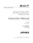
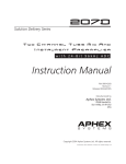
PROJECT CHANNEL™
ESSENTIAL CHANNEL STRIP
Owner’s Manual
SAFETY DECLARATIONS
TABLE OF CONTENTS
1.0 CONTROLS & INDICATORS
CAUTION: For protection against electric shock, do not remove the cover. No user serviceable parts inside.
WARNING: This equipment has been tested and found to comply with the limits for a Class A digital device pursuant to Part 15 of the FCC Rules. These limits are designed to provide reasonable protection against harmful interference when the equipment is operated in a commercial environment. This equipment generates, uses, and can
radiate radio frequency energy and, if not installed and used in accordance with the operating guide, may cause
interference to radio communications. Operation of this equipment in a residential area is likely to cause interference in which case the user will be required to correct the interference at his own expense.
The user is cautioned that changes and modifications made to the equipment without approval of the manufacturer could void the user’s authority to operate this equipment.
It is suggested that the user use only shielded and grounded cables to ensure compliance with FCC Rules.
2.0 INSTALLATION AND INTERFACING
2.1 Installation
2.2 Rear Panel View
2.3 S/PDIF output
2.4 Output Connections
2.5 Mic Input Connection
2.6 Power Supply
2.7 AC Line Connection
4
5
6
6
6
6
6
6
6
6
3.0 USING THE PROJECT CHANNEL
3.1 Using the Mic Input
3.2 Using the Instrument Input
3.3 Using Phantom Power
3.4 Using the Polarity Switch
3.5 Using the Pad
3.6 Using the Low Cut
3.7 Using the Compressor
3.8 Tone Enhancement Block
3.9 Using the Big Bottom Processor
3.10 Using the Aural Exciter Processor
3.11 Using the Level Control
7
7
7
7
7
7
8
8
8
8
8
8
4.0 WARRANTY AND SERVICE
4.1 Limited Warranty
4.2 Service Information
9
9
9
5.0 SPECIFICATIONS
5.1 General Specifications
6.0 PATENT NOTICE
10
10
11
Copyright 2012 by Aphex LLC. All rights reserved. All Aphex LLC products are trademarks or registered trademarks of Aphex LLC. Other brand
and product names are trademarks or registered trademarks of their respective holders.
Page 2
Page 3
1.0 CONTROLS AND INDICATORS
POWER INDICATION
The Aphex logo glows green when the unit is on and
ready for use.
CLASS A MIC PRE
The Project Channel works well with all professional
microphones. There is a red LED clip indicator that
will light when too much input signal is overloading
the preamp. When this happens, lower the input gain
knob until the peak LED stops flashing. If the input
gain knob is turned all the way down and the peak
LED is still flashing, you’ll need to engage the -20dB
pad and adjust the input gain knob appropriately.
The clean and stable 48V phantom supply is suitable
for even the most expensive microphones. The 12dB/
octave low cut filter starts at 70Hz. The filter is a
useful tool for removing unwanted low frequencies like
air conditioner hum or street rumble.
OPTICAL COMPRESSOR
The Project Channel includes an optical compressor
which has proven to be outstanding. It is very simple
to use with only an on/off button and ratio control. To
get deeper compression, turn up more Gain. To achieve
more gain reduction, turn up the ratio control. Note
that the units output level may need to be boosted once
the compressor has been used to control the dynamics
of the signal.
Instrument
input
allows connection of a guitar
or bass.
Rear Panel Connections
METERS
Meters are provided for peak output level and the compressor’s gain reduction. The output level bar graph
will move upwards indicating level, and the gain reduction bar graph will move downwards indicating gain
reduction.
The output level meter is DBFS. It is meant to match
the digital input meter of your DAW when using the S/
PDIF coaxial digital output of the Project Channel with
an audio interface.
OUTPUT CONTROL
Once all processing is set where you want it, the output
level may need to be adjusted. 0dB on the peak meter is
equal to +24dBU for the analog outputs.
Input gain adjusts
the input level of
both the mic and
instrument level
Red clip
light
indicates
input
clipping.
Page 4
DIGITAL AUDIO
The Project Channel supplies an industry standard, coaxial, stereo S/PDIF digital audio output. The signal appears
on both channels as a mono signal. Sample rate options are available at the front panel.
TONE ENHANCEMENT BLOCK
This section includes the popular Aphex Big Bottom
and Aural Exciter processors. These features increase
power, punch and presence without adding noise or
an increase in output level. As a real plus, they are also
very easy to adjust.
PAD
When pressed,
turns on the
-20dB input
pad.
48V
When
pressed,
turns on the
microphone
48V phantom
power.
Invert polarity
when pressed,
inverts the
polarity
(phase) of the
mic input.
Lo Cut
Switches on
the 70Hz Low
Cut filter.
DBFS peak
output meter.
Compressor
Turns on
the optical
compressor
circuit.
TRS balanced
1/4” output
switchable
between
-10dBV and
+4dBu.
S/PDIF
OUTPUT
Coaxial,
75Ohm digital
output.
Ratio
Controls
the
amount of
gain reduction for the
compressor.
Select an
internal
sample
rate with
the SELECT
button.
The GR meter displays the amount
of gain reduction when the compressor is on.
BIG-BOTTOM
FREQ
Adjusts the
frequency
below which
enhancement
takes place.
BIG-BOTTOM
AMOUNT
Adjusts the
strength
(boost) of the
Big Bottom
effect.
MIC INPUT
Works with all standard microphones,
phantom powered
or passive. Phantom
power activated
from front panel.
+4dBu
Balanced XLR
Output.
BB/AX ON
Switches the BB/AX on/
off. Provides full true
bypass of the circuits
when off.
AURAL
EXCITER
FREQ
Adjusts
frequency
above which
enhancement
takes place.
AURAL
EXCITER
AMOUNT
Adjusts the
strength
(boost) of
the Aural
Exciter
effect.
OUTPUT
Adjusts the
final processed output
level as seen
on the PEAK
meter.
Page 5
2.0 INSTALLATION & INTERFACING
3.0 USING THE PROJECT CHANNEL
2.1 INSTALLATION
The Project Channel occupies a single rack space
(45mm or 1-3/4 inches) of a standard EIA equipment
rack.
When rack mounting, use appropriate cushioned rack
screws. Try not to position the Project Channel directly
above devices that generate excessive heat such as
power amplifiers.
CAUTION: Some ribbon mics will be damaged by
phantom power. Please consult your ribbon mic’s
manual before connecting it to the Project Channel.
CAUTION: Shut off the phantom power before plugging or unplugging microphones, waiting at least 10
seconds for the voltage to fall. This also protects sensitive microphones against power inrush.
3.1 USING THE MICROPHONE INPUT
The Project Channel is perfect for all types of microphones. Dynamic, condenser, ribbon, etc. We encourage you to try every mic you own with the Project
Channel.
3.4 USING THE POLARITY SWITCH
2.2 REAR PANEL VIEW
If the clip LED is flashing RED, then the input signal
is too hot. Turn the input gain knob down until the
light no longer flashes red. If the input gain knob is all
the way down and the clip light still flashes, engage the
-20dB pad.
3.2 USING THE INSTRUMENT INPUT
2.3 S/PDIF DIGITAL OUTPUT
2.6 POWER SUPPLY
The processed signal is converted to digital in both channels at equal level as a mono signal. Simply select S/PDIF
(L) or (R) as the input in your DAW. The S/PDIF output
uses a 75 Ohm coaxial (RCA) connector.
Soft-start, overload foldback limiting, and across-theline voltage spike protection is incorporated to protect
the power supply from damage that might be caused
by component failure or power line disturbances. If
the internal fuse blows out, a catastrophic failure has
occurred and simply replacing the fuse will not fix the
problem. Due to the extensive protective measures
used, it is highly unlikely a catastrophic power supply
failure will ever occur. However, if it does, you should
contact the factory or a competent service technician
to affect repairs. There are no user serviceable parts inside.
2.4 OUTPUT CONNECTORS
There are two output connectors located on the rear
panel: one 1/4” TRS phone type and one XLR-3M type.
They can be used at the same time to feed separate equipment.
The output level at the XLR is +4dBu impedance balanced,
while the TRS balanced/unbalanced jack is switchable
between -10dBV (consumer level) and +4dBU (professional level).
If you intend to make an unbalanced output from the
XLR jack, simply take “hot” from pin 2 and use pin 1 for
ground. Leave pin 3 unconnected or grounded. Never
ground pin 2.
2.5 MIC INPUT CONNECTION
The microphone input uses the standard XLR-3F type.
Use only properly wired balanced mic cables.
Page 6
tom power is on can sometimes damage a mic because
of power inrush. Switch off the phantom power first
and wait for the mic to go silent before unplugging.
2.7 AC LINE CONNECTION
The Project Channel is internally powered from a standard
IEC power receptacle on the rear panel. Be sure you use a
power cord that is approved for use in your jurisdiction.
The Project Channel’s internal power supply is designed
to operate from all nominal power sources from 100 to
240 volts a.c. at 50/60Hz without requiring the user to
change any settings.
The Project Channel can also be used as a high quality
direct box. When an instrument cable is plugged in to
the Instrument input on the front panel, the rear panel
XLR input is bypassed. This allows the user to keep
a microphone connected to the rear panel and simply
insert an instrument cable in to the front panel instrument input when D.I. functions are required. You will
be able to achieve proper input levels no matter what
kind of pickups are used. Single coil passive pickups
will work just as well as active humbuckers. Be aware
the single coil pickups can receive hum from electrical
fields in the air. Hum from single coil pickups can be
reduced or eliminated by repositioning the guitar. Buzz
can not be canceled, it can only be dealt with by conductive shielding installed in the wiring cavities of guitars and must be grounded.
3.3 USING PHANTOM POWER
Active microphones that take power through the standard mic cable fall into a class called “phantom powered” mics. The power is called “phantom” because it
rides the mic cable invisibly, without interfering with
the audio signal carried on the same wires.
The industry standard phantom power source is positive 48 volts d.c. (+/- 10%) supplied to pins 2 and 3
through precision low noise 6.81KΩ resistors.
Plugging and Unplugging a microphone when phan-
Phase reversing can be helpful when using multiple
microphones on the same source. For example, using
two microphones on a guitar speaker cabinet. You
may get a “nasal” or hollow effect when both mics are
on. Changing the polarity of one mic will often clear
up the problem. It is always worth the time to experiment with mic polarity.
3.5 USING THE PAD
The -20dB pad is an attenuator that drops the level
coming in to the input. Its purpose is to give you a way
of preventing overload of the preamp when incoming
signals become excessive.
In the Project Channel, we provided a pad of -20dB.
That means when the pad is on, the net gain of the
preamp is 20dB lower. There are times that the input
may be overloaded even with the GAIN control set all
the way down. For example, a bass player with active
pickups and an aggressive playing style might peak the
instrument input. Or a microphone on a kick drum or
snare drum could do it. Engage the pad and 26dB of
headroom will be provided allowing you to better control the input signal.
3.6 USING LOW CUT
In the real world, mics pick up all sorts of unwanted
low frequencies such as handling noise, wind rumble,
etc. We designed into the Project Channel a very effective way of cutting out these low frequencies. Switching
on the LOW CUT FILTER rolls off all frequencies below
70Hz at 12dB per octave.
3.7 USING THE COMPRESSOR
Page 7
3.0 USING THE PROJECT CHANNEL
4.0 WARRANTY & SERVICE
3.10 AURAL EXCITER
The Project Channel’s optical compressor is very simple
to use. There is only one obvious control: RATIO. To
get more compression depth, turn up the input gain.
The RATIO control allows you to obtain more gain
reduction.
4.1 Limited Warranty
PERIOD
The gain reduction is displayed on the Project Channel’s 10 segment meter. You may need to boost the
units output level to compensate for the gain reduction
of the signal.
Clarity, presence, and loudness can all be enhanced
by the Aural Exciter. Start with the AX Amount at
12:00. Next, sweep the FREQ to find the best tonal
balance. Presence is best augmented with lower
settings. Air is added with higher settings. Finally,
readjust the AX Amount for the right amount of brilliance. Be conservative. Use the BB/AX on/off switch
to compare the original signal to the enhanced
signal.
3.8 USING THE TONE ENHANCEMENT BLOCK
3.11 USING THE OUTPUT LEVEL CONTROL
Once the signal passes through the compressor it
encounters the Big Bottom low frequency enhancer
and the Aural Exciter high frequency enhancer. The
whole block is bypassed with the BB/AX on/off pushbutton.
Once all the processing is set, the output level may
need to be adjusted. Check the input meter of the
device the Project Channels output is plugged in
to. If the input device is clipping, first turn the input
devices gain control down. If the input is still clipping, bring the OUTPUT level of the Project Channel down to compensate. Be sure that the operation
level of each device is set properly at either -10dBV or
+4dBu. At 0DBFS the analog output level is +24dBu.
Damage or deterioration resulting from: Installation and/or removal of the unit; Accident, misuse, neglect, unauthorized product modification; Failure to follow instructions in the Owner’s Manual, User Guide or other official
Aphex documentation; Repair or attempted repair by anyone not authorized by Aphex; Shipping damage – claims
must be presented to the shipper.
3.9 BIG BOTTOM
Some signals have no low bottom end. In such cases,
the Big Bottom won’t synthesize a new low end for you
and it should not be used. However, voices that contain a deep chest resonance can be augmented by the
Big Bottom.
Start by turning up the BB Amount to 12:00. Then
adjust the BB FREQ to find a frequency that lifts the
bottom. Last, reduce the BB Amount until just the right
touch of bass enhancement is felt.
One year from date of original purchase.
SCOPE
All defects in materials and workmanship.
The following are not covered:
Voltage conversions.
Units on which the serial number has been defaced, modified or removed.
WHO IS PROTECTED
This warranty will be enforceable by the original purchaser and by any subsequent owner during the warranty
period, so long as a copy of the original Bill of Sale is submitted whenever warranty service is required.
WHAT APHEX WILL PAY FOR
All labor and material expenses for covered items. Aphex will pay all return shipping charges if the repairs are covered by the warranty.
LIMITATION OF WARRANTY
No warranty is made, either expressed or implied, as to the merchantability and fitness for any particular purpose.
Any and all warranties are limited to the duration of the warrant stated above.
EXCLUSION OF CERTAIN DAMAGES
Aphex liability for any defective unit is limited to the repair or replacement of said unit, at our option, and shall not
include damages of any kind, whether incidental, consequential, or otherwise. Some states do not allow limitations
on how long an implied warranty lasts and/or do not allow the exclusion or limitation of incidental or consequential damages, so the above limitations and exclusions may not apply to you. This warranty gives you specific rights
which vary from state to state.
4.2 SERVICE INFORMATION
If it becomes necessary to return this unit for repair, you must first contact Aphex LLC. for a Return Authorization
(RMA number), which will need to be included with your shipment for proper identification. If available, repack
this unit in its original carton and packing material. Otherwise, pack the equipment in a strong carton containing
at least 2 inches of padding on all sides. Be sure the unit cannot shift around inside the carton. Include a letter
explaining the symptoms and/or defect(s). Be sure to reference the RMA number in your letter and mark the RMA
number on the outside of the carton. If you believe the problem should be covered under the terms of the warranty,
you must also include proof of purchase. Insure your shipment and send it to:
Aphex
3500 N. San Fernando Blvd.
Burbank, CA. 91505
PH: (818) 767-2929 FAX: (818) 767 -2641
Page 8
Page 9
5.0 SPECIFICATIONS
6.0 PATENT NOTICE
5.1 GENERAL SPECIFICATIONS
INPUT
Connector:
Type:
Input Z:
Instrument Connector:
Instrument Input Z:
Type:
Maximum Input Level (MIL):
CMRR:
Nominal Preamp Gain:
Phantom Power:
Pad:
OUTPUT
Connector:
Type:
Output Z Balanced:
Output Z Unbalanced:
Nominal Level
Maximum Output Level (MOL):
COMPRESSOR
BIG BOTTOM
AURAL EXCITER
Ratio:
Frequency Tune:
Mix:
500Hz to 5KHz
OFF to +12dB
THD:
IMD:
Freq Resp (FLAT):
<.01% @ +4dBu Out
<.01% @ +4dBu Out
18Hz to 24KHz +/- 1dB
Resolution:
Dynamic Range:
Noise Dither:
Level Equivalency:
OTHER SPECS
Power requirements:
Power Consumption (maximum):
Dimensions:
Depth Behind Front Panel:
Net Weight:
Shipping Weight:
5,424,488
5,359,665
1.5:1 to 10:1
50Hz to 280Hz
OFF to +12dB
Internal Sample Rates:
This product is protected under one or more of the following Aphex patents.
XLR-3M and TRS 1/4” phone jack
XLR is Impedance Balanced (may be used unbalanced); TRS is unbalanced.
XLR: 66Ω
XLR: 33Ω − TRS: 600Ω
XLR: +4dBu; TRS: -10dBV
XLR: +25dBu Unloaded; TRS: +11dBV
Frequency Tune:
MIx:
ANALOG AUDIO
DIGITAL AUDIO
XLR-3F
Transformerless, NPN active balanced, tube second stage
2KΩ nominal
1/4” TS
10MΩ nominal
Transformerless, NPN active balanced, tube second stage
0dBu
Greater than 70dB @ 60Hz
20 to 65dB
+48VDC
20dB
44.1KHz, 48KHz, 88.2KHz, 96KHz
24 Bits
Digital dynamic range greater than analog front end.
Dithered by analog preamp noise floor. Equivalent to 16-bit digital audio dither.
-20dBFS Digital = +4dBu Analog
85 to 260V~, 50-60Hz
12 Watts
19” W x 1.75” H x 8.25” overall depth (482.6mm W x 445mm H x 209.6mm overall depth)
7.5” (190.5mm)
Rack-mounted: 6lbs. (2.73kg)
9lbs. (4.1kg)
3500 N San Fernando Blvd. Burbank, CA 91505 USA
PH: 818.767.2929 FAX: 818.767.2641
www.APHEX.com
All specifications are subject to change without notice.
Page 10
Page 11