1
List of commands
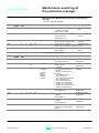
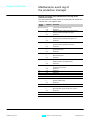
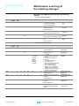
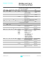
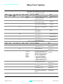
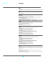
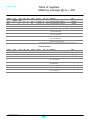
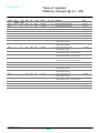
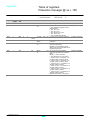
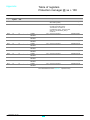
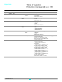
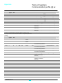
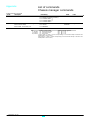
Metering-manager commands
Appendix
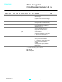
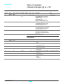
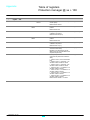
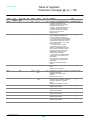
Cmd #
53298
Description
Enter configuration mode
Parameter(s)
P1 = 3 (1)
P2 = 8 (2)
P3 = control word read in register 3300 of the metering
manager
Mode
Label
Protected In_mCfg
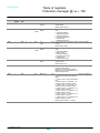
53299
Exit configuration mode and
activate the new parameters.
P1 = 3 (1)
P2 = 8 (2)
P3 = control word read in register 3300 of the metering
manager
Protected
Out_mCfg
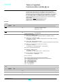
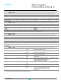
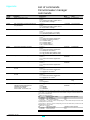
61952
Reset minimeters / maximeters
in the metering manager
P1 = 4 (1)
P2 = 8 (2)
P3 = bitmap of minimeters to reset (3)
P4 = bitmap of maximeters to reset (3)
Protected
Reset_m_M
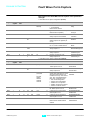
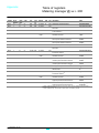
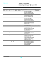
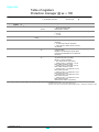
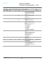
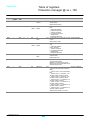
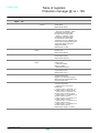
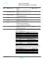
53762
Reset of current demand
maximums
P1 = 3 (1)
P2 = 8 (2)
P3 = bitmap of maximum values to reset (4)
Protected
ResetI_PeakDmd
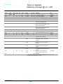
53763
Reset of power demand
maximums
P1 = 3 (1)
P2 = 8 (2)
P3 = bitmap of maximum values to reset (5)
Protected
ResetP_PeakDmd
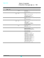
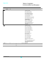
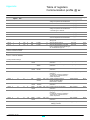
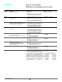
53760
Preset or reset the energy
counters
P1 = 3 to 32 (1)
P2 = 8 (2)
P3 = bitmap of counters to preset or reset (6)
P4 to P7 = first counter to preset according to P3
P8 to P11 = second counter to preset according to P3
P28 to P32 = seventh counter to preset according P3.
Protected
PresetAccEnCtr
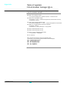
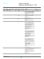
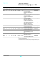
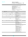
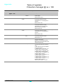
55234
Forcelog into WFC (file N° 5)
P1 = 4 (1)
P2 = 8 (2)
P3 = bitmap of file N° 5 = 0x0000
P4 = bitmap of file N° 5 = 0x0010
Shared
Protected
Forcelog
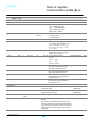
(1)
Parameter P1 for the circuit-breaker manager command interface contains the total number of command
parameters, including P1.
(2)
The value "8" for parameter P2 informs the circuit-breaker manager command interface that the metering
manager must run the command.
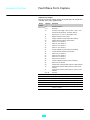
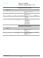
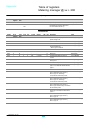
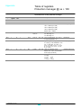
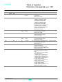
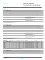
(3)
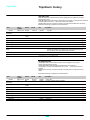
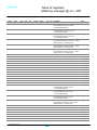
Bitmap for reset of minimeters / Maximeters
Bit
minimeters / Maximeters
Affected real-time measurement registers
0 (0x0001)
Currents
1016 to 1027
1 (0x0002)
Current unbalance
1028 to 1032
3 (0x0008)
Voltages
1000 to 1007
4 (0x0010)
Voltage unbalance
1008 to 1015
6 (0x0040)
Frequency
1054
7 (0x0080)
Power, PF
1034 to 1053
11 (0x800)
Fundamental, THD
1056 to 1118
13 (0x2000) V_Crest
1119 to 1124
14 (0x4000) I_Crest
1125 to 1128
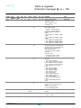
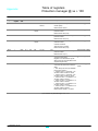
(4)
Bitmap for
Bit
1 (0x0002)
2 (0x0004)
3 (0x0008)
4 (0x0010)
reset of current demand maximums
Maximum of current demand
Phase 1
Phase 2
Phase 3
Neutral
Affected data registers
2204 + 3005 to 3007 + 3026
2205 + 3008 to 3010 + 3026
2206 + 3011 to 3013 + 3026
2207 + 3014 to 3016 + 3026
to
to
to
to
3028
3028
3028
3028
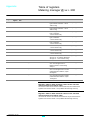
(5)
Bitmap for reset of power demand maximums
Bit
Maximums of Power demand
4 (0x0010)
Active power
8 (0x0100)
Reactive power
12 (0x1000)
Apparent power
Affected data registers
2225 to 2229 + 3017 to 3019 + 3029 to 3031
2230 to 2235 + 3020 to 3022 + 3029 to 3031
2236 to 2241 + 3023 to 3025 + 3029 to 3031
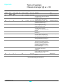
(6)
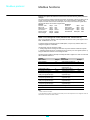
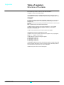
A number of counters may be preset or reset at the same time. Each counter is coded over four 16-bit
registers.
The counters to be preset are indicated in the bitmap. The values to be preset are transmitted as parameters,
in the same order as the bits set to one, starting with the least significant. The number of counters to be
transmitted is equal to the number of bits set to one in the bitmap.
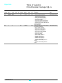
Bit
Energy counter
Affected data registers
0 (0X0001) All the counters are simply reset
1 (0X0002) Total Active-Energy
2000 to 2003
2 (0X0004) Total Reactive-Energy
2004 to 2007
3 (0X0008) Total Active-Energy IN (positively incremented)
2008 to 2011
4 (0X0010) Total Active-Energy OUT(negatively incremented)
2012 to 2015
5 (0X0020) Total Reactive-Energy IN (positively incremented)
2016 to 2019
6 (0X0040) Total Reactive-Energy OUT(negatively incremented)
2020 to 2023
7 (0X0080) Total Apparent-Energy
2024 to 2027
COMBT32AK_EN.doc
117
Modbus Communication Option
Schneider Electric