1
Smootharc
MMA 170
O P E R AT I N G M A N U A L
Welcome to a better way of welding
Congratulations on puchasing the Smootharc MMA 170
welding machine.
The products in BOC's manual metal arc range perform with reliability and have
the backing of one of South Pacific's leading welding suppliers.
This operating manual provides the basic knowledge required for MMA and
DC TIG welding, as well as highlighting important areas of how to operate the
Smootharc MMA 170 welding machine.
BOC equipment and technical support is available through our national BOC
Customer Service Centre or contact your local Gas & Gear outlet.
Important Notice: This document has been prepared by BOC Limited ABN 95 000 029 729 ('BOC'),
as general information and does not contain and is not to be taken as containing any specific instructions.
The document has been prepared in good faith and is professional opinion only. Information in this document
has been derived from third parties, and though BOC believes it to be reliable as at the time of printing, BOC
makes no representation or warranty as to the accuracy, reliability or completeness of information in this
document and does not assume any responsibility for updating any information or correcting any error or
omission which may become apparent after the document has been issued. Neither BOC nor any of its agents
has independently verified the accuracy of the information contained in this document. The information in this
document is commercial in confidence and is not to be reproduced. The recipient acknowledges and agrees
that it must make its own independent investigation and should consider seeking appropriate professional
recommendation in reviewing and evaluating the information. This document does not take into account the
particular circumstances of the recipient and the recipient should not rely on this document in making any
decisions, including but not limited to business, safety or other operations decisions.
Except insofar as liability under any statute cannot be excluded, BOC and its affiliates, directors, employees,
contractors and consultants do not accept any liability (whether arising in contract, tort or otherwise) for any
error or omission in this document or for any resulting loss or damage (whether direct, indirect, consequential
or otherwise) suffered by the recipient of this document or any other person relying on the information
contained herein. The recipient agrees that it shall not seek to sue or hold BOC or their respective agents liable
in any such respect for the provision of this document or any other information.
2
Contents
Welcome to a better way of welding
2
1.0 Recommended Safety Precautions
4
1.1 Health Hazard Information
1.2 Personal Protection
4.0 Machine Specifications and Contents 28
4.1 Operating Controls
28
4
5.0 Operating Functions
29
4
5.1 Welding selections
29
1.3 Electrical Shock
6
5.2 Earthing
29
1.4 User Responsibility
6
6.0 Technical Specifications
30
2.0Manual Metal Arc Welding Process
(MMAW)
7
7.0 Periodic Maintenance
31
2.1 Introduction
7
7.1 Daily Maintenance
31
2.2 Process
7
7.2 Troubleshooting
31
2.3 Welding Machine
7
8.0 Terms of Warranty
32
2.4 Welding Technique
8
8.1 Terms of Warranty
32
2.5 Electrode Selection
8
8.2 Limitations on Warranty
32
8.3 Warranty Repairs
32
9.0 Recommended Safety Guidelines 33
2.6 Types of Joints
11
2.7 Fillet Welds
12
2.8Typical Defects Due to Faulty Technique
15
3.0Gas Tungsten Arc Welding (GTAW/TIG)17
3.1 Introduction
17
3.2 Process
17
3.3 Process Variables
18
3.4 Welding Techniques 19
3.5 Shielding Gas Selection
20
3.6 Consumable Selection
21
3.7Typical Welding Joints for Gas Tungsten
Arc Welding
25
3
1.0 Recommended Safety Precautions
1.1 Health Hazard Information
The actual process of welding is one that
can cause a variety of hazards.
All appropriate safety equipment should be
worn at all times, i.e. headwear, respiratory,
hand and body protection. Electrical equipment
should be used in accordance with the
manufacturer’s recommendations.
Eyes:
The process produces ultra violet rays that
can injure and cause permanent damage.
Fumes can cause irritation.
Skin:
Arc rays are dangerous to uncovered skin.
Inhalation:
Welding fumes and gases are dangerous to
the health of the operator and to those in
close proximity. The aggravation of pre-existing
respiratory or allergic conditions may occur in
some workers. Excessive exposure may cause
conditions such as nausea, dizziness, dryness
and irritation of eyes, nose and throat.
•Fumes from the welding of some metals could
have an adverse effect on your health. Don’t
breathe them in. If you are welding on material
such as stainless steel, nickel, nickel alloys
or galvanised steel, further precautions are
necessary.
•Wear a respirator when natural or forced
ventilation is not good enough.
Eye protection
A welding helmet with the appropriate welding
filter lens for the operation must be worn at all
times in the work environment. The welding arc
and the reflecting arc flash gives out ultraviolet
and infrared rays. Protective welding screen and
goggles should be provided for others working
in the same area.
Clothing
Suitable clothing must be worn to prevent
excessive exposure to UV radiation and
sparks. An adjustable helmet, flameproof loose
fitting cotton clothing buttoned to the neck,
protective leather gloves, spats, apron and steel
capped safety boots are highly recommended.
1.2 Personal Protection
Recommended filter shades for
arc welding
Respiratory
Less than 150 amps
Shade 10*
Confined space welding should be carried out
with the aid of a fume respirator or air supplied
respirator as per AS/NZS 1715 and AS/NZS
1716 Standards.
150 to 250 amps
Shade 11*
250 to 300 amps
Shade 12
300 to 350 amps
Shade 13
Over 350 amps
Shade 14
•You must always have enough ventilation in
confined spaces. Be alert to this at all times.
•Keep your head out of the fumes rising from
the arc.
4
*Use one shade darker for aluminium
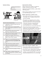
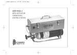
Cylinder Safety
Cylinder Valve Safety
1 Cylinder valve hand-wheel
2 Back-plug
3 Bursting disc
When moving cylinders, ensure that the valve is
not accidentally opened in transit.
1
Before operating a cylinder valve:
2
3
Backview of typical cylinder valve
Operator wearing personal
protective equipment (PPE)
in safe position
Ten Points about Cylinder Safety
1
Read labels and Material Safety Data Sheet
(MSDS) before use.
2
Store upright and use in well ventilated,
secure areas away from pedestrian or vehicle
thoroughfare.
3
Guard cylinders against being knocked
violently or being allowed to fall.
4
Wear safety shoes, glasses and gloves when
handling and connecting cylinders.
5
Always move cylinders securely with an
appropriate trolley. Take care not to turn the
valve on when moving a cylinder.
6
Keep in a cool, well ventilated area, away
from heat sources, sources of ignition and
combustible materials, especially flammable
gases.
7
Keep full and empty cylinders separate.
8
Keep ammonia-based leak detection
solutions, oil and grease away from cylinders
and valves.
9
10
When working with cylinders or operating
cylinder valves, ensure that you wear
appropriate protective clothing – gloves, boots
and safety glasses.
Never use force when opening or closing
valves.
Don’t repaint or disguise markings and
damage. If damaged, return cylinders to BOC
immediately.
•Ensure that the system you are connecting
the cylinder into is suitable for the gas and
pressure involved.
•Ensure that any accessories (such as hoses
attached to the cylinder valve, or the system
being connected to) are securely connected.
A hose, for example, can potentially flail
around dangerously if it is accidentally
pressurised when not restrained at both ends.
•Stand to the side of the cylinder so that
neither you nor anyone else is in line with the
back of the cylinder valve. This is in case a
back-plug is loose or a bursting disc vents. The
correct stance is shown in the diagram above.
When operating the cylinder valve:
•Open it by hand by turning the valve hand-wheel
anti-clockwise. Use only reasonable force.
•Ensure that no gas is leaking from the cylinder
valve connection or the system to which the
cylinder is connected. DO NOT use ammoniabased leak detection fluid as this can damage
5
the valve. Approved leak detection fluid, can be
obtained from a BOC Gas & Gear™centre.
• Always disconnect mains power before
investigating equipment malfunctions.
•When finished with the cylinder, close the
cylinder valve by hand by turning the valve
hand-wheel in a clockwise direction. Use only
reasonable force.
• Parts that are broken, damaged, missing or
worn should be replaced immediately.
• Equipment should be cleaned periodically.
Remember NEVER tamper with the valve.
If you suspect the valve is damaged, DO
NOT use it. Report the issue to BOC and
arrange for the cylinder to be returned
to BOC.
BOC stock a huge range of personal protective
equipment. This combined with BOC’s extensive
Gas and Gear network ensures fast, reliable
service throughout the South Pacific.
1.3 Electrical Shock
•Never touch ‘live’ electrical parts.
•Always repair or replace worn or
damaged parts.
•Disconnect power source before
performing any maintenance or service.
•Earth all work materials.
•Never work in moist or damp areas.
Avoid electric shock by:
PLEASE NOTE that under no circumstances
should any equipment or parts be altered
or changed in any way from the standard
specification without written permission
given by BOC. To do so, will void the
Equipment Warranty.
•Wearing dry insulated boots
•Wearing dry leather gloves
•Never changing electrodes with bare
hands or wet gloves
•Never cooling electrode holders in water
•Working on a dry insulated floor where
possible
•Never hold the electrode and holder
under your arm.
1.4 User Responsibility
• Read the Operating Manual prior to
installation of this machine.
• Unauthorised repairs to this equipment may
endanger the technician and operator and will
void your warranty. Only qualified personnel
approved by BOC should perform repairs.
6
Further information can be obtained
from Welding Institute of Australia
(WTIA) Technical Note No.7
‘Health and Safety Welding’
Published by WTIA,
PO Box 6165 Silverwater NSW 2128
Phone (02) 9748 4443.
2.0 Manual Metal Arc Welding
Process (MMAW)
2.1 Introduction
Arc welding, although in the past principally
the tool of tradesmen and fabricators, has
in recent years found increasing usage with
small workshops, farmers, handyman-hobbyists
amongst others. This has been brought about
by the introduction of low-cost portable arc
welding machines and the ready availability
of small diameter electrodes and thinner
section construction materials. Provided the
operator is familiar with the basic principles and
techniques, arc welding can be a fast, efficient
and safe method of joining metals.
The main purpose of this manual is to help
the welder with limited experience to obtain
a better understanding of the process, and to
acquire a reasonable degree of proficiency in
the least possible time. Even welders with some
experience will benefit from the information in
this manual.
2.2 Process
Manual Metal Arc welding is the process of
joining metals where an electric arc is struck
between the metal to be welded (parent metal)
and a flux-coated filler wire (the electrode).
The heat of the arc melts the parent metal and
the electrode which mix together to form, on
cooling, a continuous solid mass.
Flux Covering
Core Wire
Weld Metal
Slag
Before arc welding can be carried out, a suitable
power source is required. Two types of power
sources may be used for arc welding, direct
current (DC) or alternating current (AC).
The essential difference between these two
power sources is that, in the case of DC, the
current remains constant in magnitude and
flows in the same direction. Similarly, the voltage
in the circuit remains constant in magnitude and
polarity (i.e. positive or negative).
In the case of AC however, the current flows
first in one direction and then the other.
Similarly, the voltage in the circuit changes from
positive to negative with changes in direction
of current flow. This complete reversal is called
a ‘half cycle’ and repeats as long as the current
flows. The rate of change of direction of current
flow is known as the ‘frequency’ of the supply
and is measured by the number of cycles
completed per second. The standard frequency
of the AC supply in Australia is 50 Hz (Hertz).
2.3 Welding Machine
The most important consideration when
contemplating the use of arc welding for
the first time is the purchase of a suitable
welding machine.
BOC supplies a popular range of arc welding
machines. Machines range from small portable
welders that operate from standard 240 Volt
household power to heavy-duty welders used
by the largest steel fabricators.
Arc
Weld Pool
Workpiece
7
•selection of the correct electrode
Lift-TIG
•selection of the correct size of the
electrode for the job
•correct welding current
•correct arc length
•correct angle of electrode to work
•correct travel speed
•correct preparation of work to be welded.
2.5 Electrode Selection
Basic Welding Machine and Cables
The choice of welding machine is based mostly
on the following factors:
•primary voltage, e.g. 240 Volt or 380 Volt
•output amperage required, e.g. 140 amps
•output required, e.g. AC or DC +/•duty cycle required, e.g. 35% @ 140 amps
•method of cooling, e.g. air‑cooled or
oil‑cooled method of output amperage
control, e.g. tapped secondary lugs
•or infinitely variable control.
For example, the Smootharc 170 connects to 240
Volt supply (15 amps Input), has an output of 170
amps DC @ 50% duty cycle.
Having decided on a welding machine, appropriate
accessories are required.These are items such as
welding cables, clamps, electrode holder, chipping
hammer, helmet, shaded and clear lenses, scull cap,
gloves and other personal protective equipment.
BOC stocks a huge range of personal protective
equipment. This combined with BOC’s
extensive network ensures fast reliable service
throughout the South Pacific.
2.4 Welding Technique
Successful welding depends on the
following factors:
8
As a general rule the selection of an electrode
is straight forward, in that it is only a matter of
selecting an electrode of similar composition
to the parent metal. It will be found, however,
that for some metals there is a choice of several
electrodes, each of which has particular properties
to suit specific classes of work. Often, one
electrode in the group will be more suitable for
general applications due to its all round qualities.
The table (page 9) shows just a few of the wide
range of electrodes available from BOC with
their typical areas of application.
For example, the average welder will carry out
most fabrication using mild steel and for this
material has a choice of various standard BOC
electrodes, each of which will have qualities
suited to particular tasks. For general mild steel
work, however, BOC Smootharc 13 electrodes
will handle virtually all applications. BOC
Smootharc 13 is suitable for welding mild steel in
all positions using AC or DC power sources. Its
easy-striking characteristics and the tolerance it
has for work where fit-up and plate surfaces are
not considered good, make it the most attractive
electrode of its class. Continuous development
and improvement of BOC Smootharc 13 has
provided in-built operating qualities which
appeals to the beginner and experienced
operator alike. For further recommendations
on the selection of electrodes for specific
applications, see table page 9.
Electrodes and Typical Applications
Name
AWS Classification
Application
BOC Smootharc 13
E6013
A premium quality electrode for general structural and
sheet metal work in all positions including vertical down
using low carbon steels
BOC Smootharc 24
E7024
An iron powder electrode for high speed welding for
H-V fillets and flat butt joints. Medium to heavy structural
applications in low carbon steels
BOC Smootharc 18
E7018-1
A premium quality all positional hydrogen controlled
electrode for carbon steels in pressure vessel applications
and where high integrity welding is required and for
free-machining steels containing sulphur
BOC Smootharc S 308L
E308L
BOC Smootharc S 316L
E316L
Rutile basic coated low carbon electrodes for
welding austenitic stainless steel and difficult to weld
material
BOC Smootharc S 309L
E309L
Rutile basic coated low carbon electrode for welding
mild steel to stainless steel and difficult to weld material
Electrode Size
Welding Current
The size of the electrode is generally dependent
on the thickness of the section being welded,
and the larger the section the larger the
electrode required. In the case of light sheet
the electrode size used is generally slightly
larger than the work being welded. This means
that if 1.5 mm sheet is being welded, 2.0 mm
diameter electrode is the recommended size.
The following table gives the recommended
maximum size of electrodes that may be used
for various thicknesses of section.
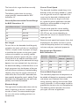
Correct current selection for a particular
job is an important factor in arc welding.
With the current set too low, difficulty is
experienced in striking and maintaining a stable
arc. The electrode tends to stick to the work,
penetration is poor and beads with a distinct
rounded profile will be deposited.
Recommended Electrode Sizes
Average Thickness
of Plate or Section
Maximum Recommended
Electrode Diameter
≤1.5 mm
2.0 mm
1.5–2.0 mm
2.5 mm
2.0–5.0 mm
3.15 mm
5.0–8.0 mm
4.0 mm
≥8.0 mm
5.0 mm
Excessive current is accompanied by overheating
of the electrode. It will cause undercut, burning
through of the material, and give excessive
spatter. Normal current for a particular job may
be considered as the maximum which can be
used without burning through the work, overheating the electrode or producing a rough
spattered surface, i.e. the current in the middle
of the range specified on the electrode package
is considered to be the optimum.
In the case of welding machines with separate
terminals for different size electrodes, ensure
that the welding lead is connected to the
correct terminal for the size electrode being
used. W
hen using machines with adjustable
current, set on the current range specified.
9
The limits of this range should not normally
be exceeded.
The following table shows the current
ranges generally recommended for BOC
Smootharc 13.
Generally Recommended Current Range
for BOC Smootharc 13
Size of Electrode (mm)
Current Range (Amp)
2.5
60–95
3.2
110–130
4.0
140–165
5.0
170–260
Arc Length
To start the arc, the electrode should be gently
scraped on the work until the arc is established.
There is a simple rule for the proper arc length;
it should be the shortest arc that gives a good
surface to the weld. An arc too long reduces
penetration, produces spatter and gives a rough
surface finish to the weld. An excessively short
arc will cause sticking of the electrode and rough
deposits that are associated with slag inclusions.
For downhand welding, it will be found that an arc
length not greater than the diameter of the core
wire will be most satisfactory. Overhead welding
requires a very short arc, so that a minimum of
metal will be lost. Certain BOC electrodes have
been specially designed for ‘touch’ welding.These
electrodes may be dragged along the work and a
perfectly sound weld is produced.
Electrode Angle
The angle which the electrode makes with the
work is important to ensure a smooth, even
transfer of metal. The recommended angles
for use in the various welding positions are
covered later.
10
Correct Travel Speed
The electrode should be moved along in the
direction of the joint being welded at a speed
that will give the size of run required. At the
same time the electrode is fed downwards
to keep the correct arc length at all times.
As a guide for general applications the table
below gives recommended run lengths for
the downhand position.
Correct travel speed for normal welding
applications varies between approximately
125–375 mm per minute, depending on
electrode size, size of run required and the
amperage used.
Excessive travel speeds lead to poor fusion, lack
of penetration, etc. Whilst too slow a rate of
travel will frequently lead to arc instability, slag
inclusions and poor mechanical properties.
Run Length per Electrode –
BOC Smootharc 13
Electrode
Size (mm)
Electrode
Length (mm)
Run Length (mm)
Minimum
Maximum
4.0
350
175
300
3.2
350
125
225
2.5
350
100
225
Correct Work Preparation
The method of preparation of components to
be welded will depend on equipment available
and relative costs. Methods may include
sawing, punching, shearing, lathe cut-offs, flame
cutting and others. In all cases edges should be
prepared for the joints that suit the application.
The following section describes the various
joint types and areas of application.
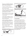
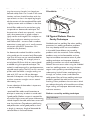
2.6 Types of Joints
Double ‘V’ Butt Weld
Used on plate of 12 mm and over
in thickness when welding can
be applied from both sides. It
allows faster welding and greater
economy of electrodes than a
single ‘V’ preparation on the same
thickness of steel and also has less
of a tendency to distortion as weld
contraction can be equalised.
Butt Welds
A butt weld is a weld made between two
plates so as to give continuity of section. Close
attention must be paid to detail in a butt weld
to ensure that the maximum strength of the
weld is developed. Failure to properly prepare
the edges may lead to the production of faulty
welds, as correct manipulation of the electrode
is impeded.
Butt Weld with Backing Material
When square butt welds or single ‘V’
welds cannot be welded from both
sides it is desirable to use a backing
bar to ensure complete fusion.
Butt Welding
FACE REINFORCEMENT
WELD FACE
ROOT FACE
Single ‘U’ Butt Weld
Used on thick plates an alternative
to a single ‘V’ preparation. It has
advantages as regards speed
of welding. It takes less weld
metal than a single ‘V’, there is
less contraction and therefore a
lessened tendency to distortion.
Preparation is more expensive
than in the case of a ‘V’, as
machining is required. The type of
joint is most suitable for material
over 40 mm in thickness.
ROOT GAP
Two terms relating to the preparation of butt
welds require explanation at this stage.
They are:
•Root Face: the proportion of the prepared
edge that has not been bevelled.
Double ‘U’ Butt Weld
For use on thick plate that is
accessible for welding from both
sides. For a given thickness it is
faster, needs less weld metal and
causes less distortion than a single
‘U’ preparation.
•Root Gap: the separation between root
faces of the parts to be joined.
WELD BEADS
Various types of butt welds are in common
use and their suitability for different thickness
of steel are described as follows:
WELD BEADS
Horizontal Butt Weld
LAYERS
ELECTRODE
Square Butt Weld
WELD BEADS
The edges are not prepared but
are separated slightly to allow
fusion through the full thickness
of the steel. Suitable for plate up
to 6 mm in thickness.
LAYERS
Single ‘V’ Butt Weld
This is commonly used for plate up
to 16 mm in thickness and on metal
of greater thickness where access
is available from only one
side.
LAYERS
WELD POOL
SLAG
LAYERS
WELD METAL
The lower member in this case is
bevelled to approximately
15° and
70˚ - 85˚
the upper member 45°, making
an included angle of 60°. This
ARC
preparation provides
a ledge on
the lower member, which tends
WELD BEADS
to retain the molten
metal.
DIRECTION OF WELDING
WELD BEADS
EL
WELD
SLAG
WELD METAL
LAYERS
ELECTRODE
70˚ - 8
WELD BEADS
WELD POOL
SLAG
WELD METAL
11
ARC
General notes on Butt Welds
LAYERS
Electrode Angle for Subsequent Layers
The first run in a prepared butt weld should
be deposited with an electrode not larger than
4.0 mm. The angle of the electrode for the
various runs in a butt weld is shown.
It is necessary to maintain the root gap by
tacking at intervals or by other means, as it will
tend to close during welding.
All single ‘V’, single ‘U’ and square butt welds should
have a backing run deposited on the underside of
the joint; otherwise 50% may be deducted from the
permissible working stress of the joint.
Before proceeding with a run on the underside
of a weld it is necessary to remove any surplus
metal or under penetration that is evident on
that side of the joint.
Butt welds should be overfilled to a certain
extent by building up the weld until it is above
the surface of the plate. Excessive build-up,
however, should be avoided.
In multi-run butt welds it is necessary to
remove all slag, and surplus weld metal before
a start is made on additional runs; this is
particularly important with the first run, which
tends to form sharp corners that cannot be
penetrated with subsequent runs. Electrodes
larger than 4.0 mm are not generally used for
vertical or overhead butt welds.
The diagrams following indicate the correct
procedure for welding thick plate when using
multiple runs.
Electrode Angle for 1st and 2nd Layers
WELD BEADS
WELD BEADS
LAYERS
Welding Progression Angle
Electrode
70–85˚
Weld Metal
Slag
Arc
Weld Pool
Workpiece
Direction of Welding
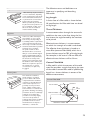
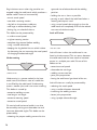
2.7 Fillet Welds
A fillet weld is approximately triangular in
section, joining two surfaces not in the same
plane and forming a lap joint, tee joint or
corner joint. Joints made with fillet welds do
not require extensive edge preparation, as is
the case with butt welded joints, since the weld
does not necessarily penetrate the full thickness
of either member. It is important that the parts
to be joined be clean, close fitting, and that all
the edges on which welding is to be carried
out are square. On sheared plate it is advisable
to entirely remove any ‘false cut’ on the edges
prior to welding. Fillet welds are used in the
following types of joints:
LAYERS
ELECTRODE
70˚ - 85˚
WELD BEADS
12
SLA
WELD METAL
WELD POOL
SLAG
WELD METAL
ARC
‘T’ Joints
A fillet weld may be placed either
on one or both sides, depending
on the requirements of the work.
The weld metal should fuse into
or penetrate the corner formed
between the two members.
Where possible the joint should
be placed in such a position as to
form a “Natural ‘V’ fillet” since
this is the easiest and fastest
method of fillet welding.
Lap Joints
In this case, a fillet weld may be
placed either on one or both
sides of the joint, depending on
accessibility and the requirements
of the joint. However, lap joints,
where only one weld is accessible,
should be avoided where possible
and must never constitute
the joints of tanks or other
fabrications where corrosion is
likely to occur behind the lapped
plates. In applying fillet welds to
lapped joints it is important that
the amount of overlap of the
plates be not less than five times
the thickness of the thinner part.
Where it is required to preserve
the outside face or contour
of a structure, one plate may
be joggled.
Corner Joints
The members are fitted as
shown, leaving a ‘V’-shaped
groove in which a fillet weld
is deposited. Fusion should be
complete for the full thickness
of the metal. In practice it is
generally necessary to have a
gap or a slight overlap on the
corner. The use of a 1.0–2.5 mm
gap has the advantage of assisting
penetration at the root, although
setting up is a problem. The
provision of an overlap largely
overcomes the problem of
setting up, but prevents complete
penetration at the root and
should therefore be kept to a
minimum, i.e. 1.0–2.5 mm.
The following terms and definitions are
important in specifying and describing
fillet welds.
Leg Length
A fusion face of a fillet weld, as shown below.
All specifications for fillet weld sizes are based
on leg length.
Throat Thickness
A measurement taken through the centre of a
weld from the root to the face, along the line
that bisects the angle formed by the members
to be joined.
Effective throat thickness is a measurement
on which the strength of a weld is calculated.
The effective throat thickness is based on a
mitre fillet (concave Fillet Weld), which has a
throat thickness equal to 70% of the leg length.
For example, in the case of a 20 mm fillet, the
effective throat thickness will be 14 mm.
Convex Fillet Weld
A fillet weld in which the contour of the weld
metal lies outside a straight line joining the toes
of the weld. A convex fillet weld of specified leg
length has a throat thickness in excess of the
effective measurement.
Convex Fillet Weld
ACTUAL THROAT
CONVEXITY
LEG
LENGH
CONC
ACTUAL T
AND EFFE
THROAT
EFFECTIVE THROAT
TH
THEORETICAL THROAT
13
Concave Fillet Weld
A fillet in which the contour of the weld is
below a straight line joining the toes of the
weld. It should be noted that a concave fillet
weld of a specified leg length has a throat
thickness less than the effective throat
thickness for that size fillet. This means that
when a concave fillet weld is used, the throat
thickness must not be less than the effective
measurement. This entails an increase in leg
length beyond the specified measurement.
Concave Fillet Weld
TY
LEG
LEG
LENGH
CONCAVITY
ACTUAL THROAT
AND EFFECTIVE
THROAT
SIZE
SIZE LEG
THEORETICAL THROAT
The size of a fillet weld is affected by the
electrode size, welding speed or run length,
welding current and electrode angle. Welding
speed and run length have an important effect
on the size and shape of the fillet, and on the
tendency to undercut.
Insufficient speed causes the molten metal
to pile up behind the arc and eventually to
collapse. Conversely, excessive speed will
produce a narrow irregular run having poor
penetration, and where larger electrodes
and high currents are used, undercut is
likely to occur.
14
Fillet Weld Data
Nominal
Fillet Size
(mm)
Minimum
Throat
Thickness
(mm)
Plate
Thickness
(mm)
Electrode
Size (mm)
5.0
3.5
5.0–6.3
3.2
6.3
4.5
6.3–12
4.0
8.0
5.5
8.0–12 & over
4.0
10.0
7.0
10 & over
4.0
Selection of welding current is important. If it is
too high the weld surface will be flattened, and
undercut accompanied by excessive spatter is
likely to occur. Alternatively, a current which is
too low will produce a rounded narrow bead
with poor penetration at the root. The first run
in the corner of a joint requires a suitably high
current to achieve maximum penetration at
the root. A short arc length is recommended
for fillet welding. The maximum size fillet which
should be attempted with one pass of a large
electrode is 8.0 mm. Efforts to obtain larger leg
lengths usually result in collapse of the metal
at the vertical plate and serious undercutting.
For large leg lengths multiple run fillets are
necessary. These are built up as shown below.
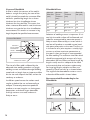
The angle of the electrode for various runs in
a downhand fillet weld is shown below.
Recommended Electrode Angles for
Fillet Welds
1st Run
2nd Run
3rd Run
Multi-run Fillet
Multi-run horizontal fillets have each run made
using the same run lengths (run length per
electrode table). Each run is made in the same
direction, and care should be taken with the
shape of each, so that it has equal leg lengths
and the contour of the completed fillet weld
is slightly convex with no hollows in the face.
Vertical fillet welds can be carried out using
the upwards or downwards technique. The
characteristics of each are: upwards – current
used is low, penetration is good, surface is
slightly convex and irregular. For multiple run
fillets large single pass weaving runs can be
used. Downwards – current used is medium,
penetration is poor, each run is small, concave
and smooth (only BOC Smootharc 13 is
suitable for this position).
The downwards method should be used for
making welds on thin material only. Electrodes
larger than 4.0 mm are not recommended for
vertical down welding. All strength joints in
vertical plates 10.0 mm thick or more should
be welded using the upward technique. This
method is used because of its good penetration
and weld metal quality. The first run of a vertical
up fillet weld should be a straight sealing run
made with 3.15 mm or 4.0 mm diameter
electrode. Subsequent runs for large fillets may
be either numerous straight runs or several
wide weaving runs.
Correct selection of electrodes is important
for vertical welding.
In overhead fillet welds, careful attention to
technique is necessary to obtain a sound weld
of good profile. Medium current is required for
best results. High current will cause undercutting
and bad shape of the weld, while low current will
cause slag inclusions. To produce a weld having
good penetration and of good profile, a short
arc length is necessary. Angle of electrode for
overhead fillets is illustrated above.
Recommended Angles for Overhead
Fillet Welds
15˚
45˚
30˚
2.8 Typical Defects Due to
Faulty Technique
Shielded metal arc welding, like other welding
processes, has welding procedure problems
that may develop which can cause defects
in the weld. Some defects are caused by
problems with the materials. Other welding
problems may not be foreseeable and may
require immediate corrective action. A poor
welding technique and improper choice of
welding parameters can cause weld defects.
Defects that can occur when using the shielded
metal arc welding process are slag inclusions,
wagon tracks, porosity, wormhole porosity,
undercutting, lack of fusion, overlapping, burn
through, arc strikes, craters, and excessive
weld spatter. Many of these welding technique
problems weaken the weld and can cause
cracking. Other problems that can occur which
can reduce the quality of the weld are arc blow,
finger nailing, and improper electrode coating
moisture contents.
Defects caused by welding technique
Slag Inclusions
SLAG INCLUSIONS
15
Slag inclusions occur when slag particles are
trapped inside the weld metal which produces a
weaker weld. These can be caused by:
•erratic travel speed
•too wide a weaving motion
•slag left on the previous weld pass
type and size of electrode and the welding
position
•holding the arc as short as possible
•pausing at each side of the weld bead when a
weaving technique is used
•letting slag run ahead of the arc.
•using a travel speed slow enough so that the
weld metal can completely fill all of the melted
out areas of the base metal.
This defect can be prevented by:
Lack of Fusion
•too large an electrode being used
•a uniform travel speed
•a tighter weaving motion
•complete slag removal before welding
•using a smaller electrode
•keeping the slag behind the arc which is done
by shortening the arc, increasing the travel speed,
or changing the electrode angle.
Undercutting
LACK OF FUSION
Lack of fusion is when the weld metal is not
fused to the base metal. This can occur between
the weld metal and the base metal or between
passes in a multiple pass weld. Causes of this
defect can be:
•excessive travel speed
•electrode size too large
UNDERCUTTING
•welding current too low
•poor joint preparation
Undercutting is a groove melted in the base
metal next to the toe or root of a weld that
is not filled by the weld metal. Undercutting
causes a weaker joint and it can cause cracking.
•letting the weld metal get ahead of the arc.
This defect is caused by:
•using a smaller diameter electrode
•excessive welding current
•increasing the welding current
•too long an arc length
•better joint preparation
•excessive weaving speed
•using a proper electrode angle.
•excessive travel speed.
On vertical and horizontal welds, it can also
be caused by too large an electrode size and
incorrect electrode angles. This defect can be
prevented by:
•choosing the proper welding current for the
16
Lack of fusion can usually be prevented by:
•reducing the travel speed
3.0 Gas Tungsten Arc Welding (GTAW/TIG)
3.1 Introduction
The Tungsten Inert Gas, or TIG process, uses
the heat generated by an electric arc struck
between a non-consumable tungsten electrode
and the workpiece to fuse metal in the joint
area and produce a molten weld pool. The arc
area is shrouded in an inert or reducing gas
shield to protect the weld pool and the
non-consumable electrode. The process may
be operated autogenously, that is, without filler,
or filler may be added by feeding a consumable
wire or rod into the established weld pool.
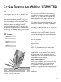
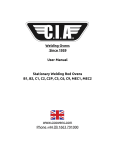
3.2 Process
1
Shielding gas
2
Arc
3
TIG filler rod
4
Weld pool
5
Collet
6
Tungsten Electrode
7
Workpiece
Shielding gas is directed into the arc area by the
welding torch and a gas lens within the torch
distributes the shielding gas evenly over the
weld area. In the torch the welding current is
transferred to the tungsten electrode from the
copper conductor. The arc is then initiated by
one of several methods between the tungsten
and the workpiece.
During TIG welding, the arc can be initiate by
several means:
5
1
6
2
3
4
Direct or alternating current power sources
with constant current output characteristics
are normally employed to supply the welding
current. For DC operation the tungsten may
be connected to either output terminal, but
is most often connected to the negative pole.
The output characteristics of the power source
can have an effect on the quality of the welds
produced.
7
Scratch Start
With this method, the tungsten electrode
is physically scratched on the surface of the
workpiece and the arc is initiated at the full
amperage set by the operator. The incidence
of the tungsten melting at the high initiation
amperage is high and tungsten inclusions in the
weld metal are quite common.
High Frequency Start
During High Frequency start, the arc will ‘jump’
towards the workpiece if a critical distance
is reached. With this method, there is no
incidence of tungsten inclusions happening. High
Frequency is only available on certain types of
machines and it can affect nearby electronic
equipment.
Schematic of the TIG welding process
17
Lift Arc™
During this method of arc initiation, the
tungsten is actually touching the workpiece.
This occurs at very low amperage that is only
sufficient to pre-heat, not melt the tungsten.
As the tungsten is moved off the plate, the arc
is established. With this method, there is little
chance of tungsten inclusion occurring.
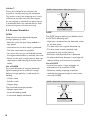
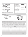
3.3 Process Variables
DCEN
When direct-current electrode-negative
(straight polarity) is used:
DCEN - Narrow bead - Deep penetration
Nozzle
Ions
Electrons
DCEP
The DCEP (reverse polarity) are different from
the DCEN in following ways:
•Electrons strike the part being welded at a
high speed.
•High heat is produced on the electrode rather
on the base metal.
•Intense heat on the base metal is produced.
•The heat melts the tungsten electrode tip.
•The base metal melts very quickly.
•The base metal remains relatively cool
compared to sing straight polarity.
•Ions from the inert gas are directed towards
the negative electrode at a relatively slow rate.
•Direct current with straight polarity does not
require post-weld cleaning to remove metal
oxides.
Use of DCEN
For a given diameter of tungsten electrode,
higher amperage can be used with straight
polarity. Straight polarity is used mainly for
welding:
•Relatively shallow penetration is obtained.
•An electrode whose diameter is too large will
reduce visibility and increase arc instability.
Use of DCEP
•Intense heat means a larger diameter of
electrode must be used with DCEP.
•Maximum welding amperage should be
relatively low (approximately six times lower
than with DCEN).
•Carbon steels
•Stainless steels
DCEP - Wide bead - Shallow penetration
•Copper alloys
The increased amperage provides:
Nozzle
•Deeper penetration
•Increased welding speed
•A narrower, deeper, weld bead.
18
Ions
Electrons
3.4 Welding Techniques
Welding techniques
Vertical
Welding Rod
60–75°
Shield gas
Nozzle
15–30°
Tungsten electrode
Direction of travel
The suggested electrode and
welding rod angles for welding
a bead on plate. The same
angles are used when making
a butt weld. The torch is held
60–75° from the metal surface.
This is the same as holding the
torch 15–30° from the vertical.
Take special note that the rod
is in the shielding gas during
the welding process.
Torch and filler metal manual control guidelines
Flat position (1G)
Horizontal position (2G)
Vertical position (3G)
Upwards progression
A = Torch travel angle – forehand technique
– push angle 10–20° (to the vertical)
B = Work angle: 90°
C = Filler metal feed angle: 10–20°
D = Arc length: 1–1.5 x electrode diameter
19
3.5 Shielding Gas Selection
Brass
With argon, the arc is stable and there is little smoke.
Cobalt-based alloys
Argon provides a stable, easy-to-control arc.
Copper nickel (Monel)
Argon gives a stable, easy-to-control arc. Also used for welding copper nickel
to steel.
Deoxidised copper
Helium is preferred as it helps greatly in counteracting thermal conductivity of
copper. A mixture of 75% helium and 25% argon (Alushield Heavy) produces a
stable arc, less heat than an arc produced with helium alone.
Nickel alloys
(Inconel)
Argon produces a very stable arc. Helium is recommended for automatic welding
at high speeds.
Mild steel
For manual welding, argon is recommended. Successful welding depends on the
skill of the welder. Helium is preferred for:
•high speed automatic welding
•where deeper penetration than with argon is required
•small HAZ
Magnesium alloys
Argon recommended with continuous high frequency AC. Produces good arc
stability and good cleaning action
0.5% Molybdenum
Pure argon or helium is recommended. For good welding ductility, welding must
be carried out in a draught-free area.
Silicon bronze
Argon decreases internal tension in base metal and in the weld since there is less
penetration with this gas compared to helium.
Stainless steel
Argon is the most commonly used gas for stainless steel. Helium can be used if
better penetration is required.
Titanium alloys
Argon produces a stable arc. Helium is recommended for high speed welding.
20
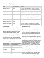
3.6 Consumable Selection
a) Welding wire
The following table includes the recommended welding consumable for the most commonly
welded materials.
Base Material
BOC Consumable
C-Mn and low Carbon steels
BOC Mild steel TIG wire
Low Alloy steels
1.25Cr/0.5Mo
Comweld CrMo1
2.5Cr/1Mo
Comweld CrMo2
Stainless Steel
304/304L
Profill 308
316/316L
Profill 316
309/309-C-Mn
Profill 309
321/Stabilised grades
Profill 347
Filler rod diameter (mm)
Thickness of metal (mm)
2
0.5–2
3
2–5
4
5–8
4 or 5
8–12
5 or 6
12 or more
21
b) Non consumable Tungstens
Tungsten Electrode Selector Chart
Base metal type
Thickness range
Desired results
Welding
current
Electrode type
Copper alloys,
Cu-NI alloys and
Nickel alloys
All
General purpose
DCSP
2% Thoriated (EW-Th2)
2% Ceriated (EW-Ce2)
Mild Steels, Carbon
Steels, Alloy Steels,
Stainless Steels and
Titanium alloys
Only thin sections
Control penetration
ACHF
Zirconiated (EW-Zr)
Only thick sections
Increase penetration
or travel speed
DCSP
2% Ceriated (EW-Ce2)
All
General purpose
DCSP
2% Thoriated (EW-Th2)
2% Ceriated (EW-Ce2)
2% Lanthanated (EWG-La2)
Only thin sections
Control penetration
ACHF
Zirconiated (EW-Zr)
Only thick sections
Increase penetration
or travel speed
DCSP
2% Ceriated (EW-Ce2)
2% Lanthanated ( EWG-La2)
22
Shielding
gas
Tungsten performance characteristics
75% Argon/
25% Helium
Best stability at medium currents. Good arc starts. Medium tendency to spit.
Medium erosion rate.
75% Argon/
25% Helium
Low erosion rate. Wide current range. AC or DC. No spitting. Consistent arc starts.
Good stability.
Argon
Use on lower currents only. Spitting on starts. Rapid erosion rates at higher currents.
75% Argon/
25% Helium
Low erosion rate. Wide current range. AC or DC. No spitting. Consistent arc starts.
Good stability.
75% Argon/
25% Helium
Best stability at medium currents. Good arc starts. Medium tendency to spit.
Medium erosion rate.
75% Argon/
25% Helium
Low erosion rate. Wide current range. AC or DC. No spitting. Consistent arc starts.
Good stability.
75% Argon/
25% Helium
Lowest erosion rate. Widest current range on DC. No spitting. Best DC arc starts and stability.
Argon
Use on lower current only. Spitting on starts. Rapid erosion rates at higher currents.
75% Argon/
25% Helium
Low erosion rate. Wide current range. No spitting. Consistent arc starts. Good stability.
Helium
Lowest erosion rate. Highest current range. No spitting. Best DC arc starts and stability.
23
Tungsten tip preparation
Tungsten Grinding
Shape by grinding longitudinally
(never radially). Remove
the sharp point to leave a
truncated point with a flat
spot. Diameter of flat spot
determines amperage capacity.
(See below)
DCSP (EN) or DCRP (EP)
= Diameter
Flat
1/4–1/2x Dia
Taper length
2–3x Dia
The included angle determines
weld bead shape and size.
Generally, as the included
angle increases, penetration
increases and bead width
decreases.
ACHP General Purpose
Max. ball
1x Dia
Ball tip by arcing on clean metal at low current DCRP (EP)
then slowly increase current to form the desired ball diameter.
Return setting to AC.
Use a medium (60 grit or
finer) aluminium oxide wheel.
Tungsten Extension
Gas Lens Parts
Standard Parts
General
purpose
3x Dia
General
purpose
3x Dia
Maximum
6x Dia
(in draft free areas)
Tungsten electrode tip shapes and current ranges
Thoriated, ceriated, and lanthanated tungsten electrodes do not ball as readily as pure or zirconiated tungsten electrodes, and as such
are typically used for DCSP welding. These electrodes maintain a ground tip shape much better than the pure tungsten electrodes. If
used on AC, thoriated and lanthanated electrodes often spit. Regardless of the electrode tip geometry selected, it is important that
a consistent tip configuration be used once a welding procedure is established. Changes in electrode geometry can have a significant
influence not only on the weld bead width, depth of penetration, and resultant quality, but also on the electrical characteristics of the
arc. Below is a guide for electrode tip preparation for a range of sizes with recommended current ranges.
Electrode Diameter (mm)
24
Diameter ar tip (mm)
Constant included angle,
(degrees)
Current range (A)
1.0
0.125
12
2–15
1.0
0.250
20
5–30
1.6
0.500
25
8–50
1.6
0.800
30
10–70
2.3
0.800
35
12–90
2.3
1.100
45
15–150
3.2
1.100
60
20–200
3.2
1.500
90
25–250
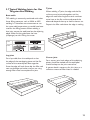
3.7 Typical Welding Joints for Gas
Tungsten Arc Welding
Butt welds
TIG welding is commonly combined with other
faster filling processes such as MMA or MIG
welding. It is therefore not uncommon to use
the same weld preparations as would have been
used for the filling process. When welding a
butt joint, centre the weld pool on the adjoining
edges. When finishing, decrease the heat
(amperage) to aid in filling the crater.
3 mm
T-joint
When welding a T-joint, the edge and the flat
surface are to be joined together, and the
edge will melt faster. Angle the torch to direct
more heat to the flat surface and extend the
electrode beyond the cup to hold a shorter arc.
Deposit the filler rod where the edge is melting.
2mm
6 mm
Lap joint
For a lap weld, form the weld pool so that
the edge of the overlapping piece and the flat
surface of the second piece flow together.
Since the edge will melt faster, dip the filler rod
next to the edge and make sure you are using
enough filler metal to complete the joint.
Corner joint
For a corner joint, both edges of the adjoining
pieces should be melted and the weld pool
should be kept on the joint centre line.
A convex bead is necessary for this joint, so a
sufficient amount of filler metal is needed.
25
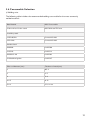
Troubleshooting guide
Problem
Cause
Excessive
1.Inadequate gas flow
electrode
2.Improper size electrode for
consumption
current required
3.Operating of reverse polarity
4.Electrode contamination
5.Excessive heating inside torch
6.Electrode oxidising during cooling
7.Shield gas incorrect
1. Increase gas flow
2. Use larger electrode
Erratic Arc
1. Incorrect voltage (arc too long)
2. Current too low for electrode size
3. Electrode contaminated
4. Joint too narrow
5.Contaminated shield gas. Dark
stains on the electrode or weld
bead indicate contamination
6.Base metal is oxidised, dirty or oily
1. Maintain short arc length
2. Use smaller electrode or increase current
3. Remove contaminated portion, then prepare again
4. Open joint groove
5.The most common cause is moisture or aspirated
air in gas stream. Use welding grade gas only. Find the
source of the contamination and eliminate it promptly.
6.Use appropriate chemical cleaners, wire brush, or
abrasives prior to welding
Inclusion of
tungsten or
oxides in
weld
1. Poor lift starting technique
1.Many codes do not allow scratch starts. Use copper
strike plate.
2.Reduce the current or use larger electrode
2.Excessive current for tungsten size
used
3.Accidental contact of electrode with
puddle
4.Accidental contact of electrode to
filler rod
5.Using excessive electrode extension
6.Inadequate shielding or excessive
drafts
7.Wrong gas
8.Heavy surface oxides not being
removed
Porosity
in Weld
Deposit
26
Solution
1.Entrapped impurities, hydrogen, air,
nitrogen, water vapour
2.Defective gas hose or loose
connection
3.Filler material is damp (particularly
aluminium)
4.Filler material is oily or dusty
3. User larger electrode or change polarity
4. Remove contaminated portion, then prepare again
5. Replace collet.Try wedge collet or reverse collet.
6. Increase gas flow post time to 1 sec per 10 amps
7. Change to proper gas (no oxygen or CO2)
3.Maintain proper arc length
4.Maintain a distance between electrode and filler metal
5.Reduce the electrode extension to recommended
limits
6.Increase gas flow, shield arc from wind, or use gas lens
7.Do not use ArO2 or ArCO2 GMAW (MIG) gases
for TIG welding
8. Joint area needs to be cleaned prior to welding
1.Do not weld on wet material. Remove condensation
from line with adequate gas pre-flow time
2. Check hoses and connections for leaks
3. Dry filler metal in oven prior to welding
4. Replace filler metal
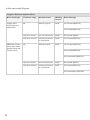
Troubleshooting guide
Problem
Cause
Solution
Porosity
in Weld
Deposit
5.Alloy impurities in the base metal
such as sulphur, phosphorous, lead
and zinc
6.Excessive travel speed with rapid
freezing of weld trapping gases
before they escape
7. Contaminated shield gas
5.Change to a different alloy composition which is
weldable.These impurities can cause a tendency to
crack when hot.
6. Lower the travel speed
1.Hot cracking in heavy section or
with metals which are hot shorts
1.Preheat. Increase weld bead cross-section size.
Change weld bead contour. Use metal with fewer
alloy impurities
2.Reverse direction and weld back into previous weld at
edge. Use Amprak or foot control to manually down
slope current
3.Preheat prior to welding. Use pure or noncontaminated gas. Increase the bead size. Prevent
craters or notches. Change the weld joint design.
4.Increase bead size. Decrease root opening. Use
preheat. Prevent craters.
5.Eliminate sources of hydrogen, joint restraint, and use
preheat
Cracking in
Welds
2.Crater cracks due to improperly
breaking the arc or terminating the
weld at the joint edge
3.Post weld cold cracking due to
excessive joint restraint, rapid
cooling or hydrogen embrittlement
4.Centreline cracks in single pass weld
5.Underbead cracking from brittle
microstructure
Inadequate
shielding
Arc Blow
Short parts
Life
1.Gas flow blockage or leak in hoses
or torch
2.Excessive travel speed exposes
molten weld to atmospheric
contamination
3. Wind or drafts
4. Excessive electrode stickout
5. Excessive turbulence in gas stream
7. Replace the shielding gas
1. Locate and eliminate the blockage or leak
2.Use slower travel speed or carefully increase the
flow rate to a safe level below creating excessive
turbulence. Use a trailing shield cup.
3. Set up screens around the weld area
4. Reduce electrode stickout. Use a larger size cup
5. Change to gas safer parts or gas lens parts
1.Induced magnetic field from DC
weld current
2.Arc is unstable due to magnetic
influence
1.Rearrange the split ground connection
1. Short water cooled leads life
1.Verify coolant flow direction. Return flow must be on
the power cable lead
2. Change cup size or type. Change tungsten position
3.Ordinary style is split and twists or jams. Change to
wedge style
4.Do not operate beyond rated capacity. Use water
cooled model. Do not bend rigid torches
2. Cup shattering or cracking in use
3. Short collet life
4. Short torch head life
2.Reduce weld current and use arc length as short as
possible
27
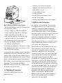
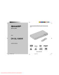
4.0 Machine Specifications and Contents
4.1 Operating Controls
1
2
Lift-TIG
3
4
7
5
8
1 Power indicator light
2 Overtemperature control indicator
3 Welding current regulator
4 On/Off switch
5 Process selector switch MMA/Lift TIG
6 Heavy duty 15A input plug
7 Negative '35' dinse connector
8 Positive '35' dinse connector
28
6
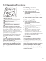
5.0 Operating Functions
5.1 Welding selections
1
2
Manual Metal Arc welding (MMA)
■■
Lift-TIG
3
4
5
■■
■■
Select the current as per the
recommendations of the consumable
manufacturer.
Select the polarity of the electrode cable as
per the recommendations (+/-)
Select the process selector switch to MMA
1 Power indicator light
2 Overtemperature control indicator
3 Welding current regulator
4 On/Off switch
5 Process selector switch MMA/Lift TIG
Always switch the machine off at the supply
switch. W
hen changing electrode or return leads
the machine's on/off switch 4 should be in the
off postion.The machine should then also be
switched off at the mains supply plug and the plug
removed from the supply socket.
The green power light 1 will illuminate when
the machine is switched on using the on/off
switch 4 .
The machine is fitted with a process selector
switch 5 that will change the function of the
machine from MMA to Lift TIG.
The machine will stop working if the temperature
reaches a certain level. (Exceeds the units duty
cycle). The overtemperature control indicator
light 2 will illuminate.
DC TIG welding (Lift TIG)
Select the current as per the
recommendations of the consumable
manufacturer.
■■ Connect the TIG torch to the negative (-)
pole of the welding machine.
■■ Select the process selector switch to
'Lift TIG'
■■ When Lift TIG is selected the tungsten
electrode can be touched onto the
workpiece. The arc will be initiated as the
electrode is moved upwards and the current
will revert to the adjusted current.
■■
5.2 Earthing
For the welding process to be most effective
it is important to ensure that there is a solid
connection between the work return clamp and
the workpiece.
Always ensure that the return clamp is as close as
practically possible to the area to be welded.
Ensure that the workpiece is clean and free from
rust, scale paint or oil and grease before affixing
the work return clamp.
29
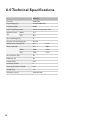
6.0 Technical Specifications
MMA170
Part No.
MMA170P
Input Voltage (V)
1PH AC240V±15%
Frequency (Hz)
50/60
Input Plug Requirement
Industrial Heavy duty 15A
Rated Current
(A)
MMA
27.5
TIG
20.3
No-load Voltage (V)
65
Output Current Range (A)
20-170
Rated Output Voltage (V)
26.8
16.8
Duty Cycle (%)
35%
100%
170A
132A
170A
132A
MMA
TIG
No-load Loss (W)
40
Efficiency (%)
80
Power Factor
0.73
Insulation Grade
F
Housing Protection Grade
IP21
Weight (kg)
7.5
Dimension (mm)
430×185×306
30
7.0 Periodic Maintenance
In maintenance of the unit, take into
consideration the rate of use and the
environment it is used in. When the unit is used
properly and serviced regularly, you will avoid
unnecessary disturbances in use and production.
7.1 Daily Maintenance
• Check that there is ample space in front of
and back of the unit for ventilation.
• Check welding settings. See 5.1 Welding
Selections
If problems in use are not solved with above
mentioned measures, please contact your local
BOC representative.
Perform the following maintenance daily:
• Clean electrode holder and TIG torch's gas
nozzle. Replace damaged or worn parts.
• Check TIG torch's electrode. Replace or
sharpen, if necessary.
• Check tightness of welding and earth cable
connections.
• Check condition of mains and welding cables
and replace damaged cables.
• See that there is enough space in front of and
back of the unit for ventilation.
7.2 Troubleshooting
Main switch signal light is not lit.
Unit does not get electricity.
• Check mains fuses and replace if necessary.
• Check mains cable and plug, replace damaged
parts.
Unit does not weld well.
Arc is uneven and goes off. Electrode gets stuck
in weld pool.
• Check welding settings and adjust when
necessary.
• Check that earth clamp is properly fixed and
that contact surface is clean and the cable is
undamaged.
Signal light for overheating is lit.
The unit has overheated. See 5.0 Operating
Functions
31
8.0 Terms of Warranty
Warranty for Smootharc MMA170
8.3 Warranty Repairs
8.1 Terms of Warranty
BOC or their Authorised Service Agent must
be informed of the warranty defects, and the
product returned within the warranty period.
BOC provides a warranty for the Smootharc
MMA170 sold by it against defects in
manufacture and materials.
•Valid for 18 months from date of purchase.
•An authorised BOC Service Agent must carry
out warranty repairs.
•Freight, packaging and insurance costs are to
be paid for by the claimant.
•No additional express warranty is given unless in
writing signed by an authorised manager of BOC.
•This warranty is in addition to any other legal
rights you may have.
•Electrode holders are not covered.
8.2 Limitations on Warranty
The following conditions are not covered:
•Non compliance with operating and
maintenance instructions such as connection
to incorrect faulty voltage supply including
voltage surges outside equipment specs, and
incorrect overloading
• Natural wear and tear, and accidental damage
• Transport or storage damage.
32
•Before any warranty work is undertaken, the
customer must provide proof of purchase and
serial number of the equipment in order to
validate the warranty.
•The parts replaced under the terms of the
warranty remain the property of BOC.
9.0 Recommended Safety Guidelines
Some safety precautions BOC recommends are as follows:
•Repair or replace defective cables immediately.
•Never watch the arc except through
lenses of the correct shade.
•In confined spaces, adequate ventilation
and constant observation are essential.
•Leads and cables should be kept clear
of passageways.
•Keep fire extinguishing equipment at a handy
location in the shop.
•Keep primary terminals and live parts
effectively covered.
•Never strike an electrode on any gas cylinder.
•Never use oxygen for venting containers.
Diagram and safety explanation
Diagram and safety explanation
Electrical safety alert
Wear dry, insulated gloves
Welding electrode causing
electric shock
Insulate
yourself from
work and ground
Fumes and gases coming from
welding process
Disconnect input power before
working on equipment
Welding arc rays
Keep head out of fumes
Read instruction manual
Use forced ventilation or local
exhaust to remove fumes
Become trained
Use welding helmet with
correct shade of filter
33
34
35
For more information on any BOC product or service call
the BOC Customer Service Centre on:
AU S TRA L I A
131 262
Email: [email protected]
Website: www.boc.com.au
NEW Z EA L AN D
0800 111 333
Email: [email protected]
Website: www.boc.co.nz
BOC Limited
ABN 95 000 029 729
Riverside Corporate Park
10 Julius Avenue
North Ryde, NSW 2113
AUSTRALIA
BOC Limited
970 – 988 Great South Road
Penrose, Auckland
NEW ZEALAND
BOC is a trading name of BOC Limited, a member of The Linde Group, © BOC Limited 2009. Reproduction without permission is strictly
prohibited. Details given in this document are believed to be correct at the time of printing. Whilst proper care has been taken in the
preparation, no liability for injury or damage resulting from its improper use can be accepted.
MP09-0116 . FDAUS . 0509