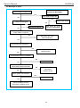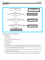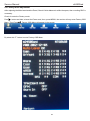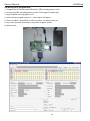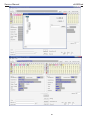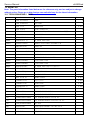
1
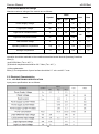
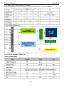
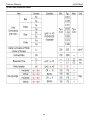
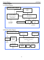
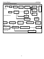
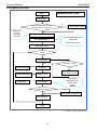
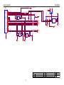
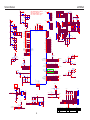
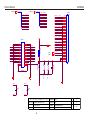
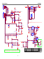
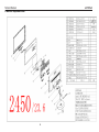
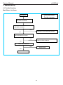
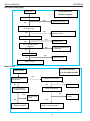
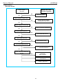
Service Manual
e2450Swd
AOC 显 示 器 维 修 手 册
Model:
1
e2450Swd
Service Manual
e2450Swd
Revision List
Version
Release Date
Revision History
TPV Model Name
TDAMN22DAHA6HAE
TDAMN22DAHA6HRE
TDAMN22DAGA6HNE
A00
Jul-29-2011
Initial release
TDBMN22DAHA1HCE
TDBMN22DAHA1H6E
TDAMN22DAHA6HNE
TDBMN22DAHA1HNE
TDB2N22DAHA1HNE
TDB2N22EAHA1HNE
A01
Dec-01-2011
Add new models
TDBMN22EAHA1HNE
TDBMN22EAHA6HNE
TDCWN22MAHA1HNJ
A02
Jan-07-2013
Add new models
TDC2N22KAHE6HNJ
2
Service Manual
e2450Swd
CONTENTS
1. Monitor Specifications ----------------------------------------------------------------------------------------- 4
1.1 Product Features --------------------------------------------------------------------------------------------- 4
1.2 Factory Preset Mode----------------------------------------------------------------------------------------- 5
2. Setup ----------------------------------------------------------------------------------------------------------------- 6
2.1 Contents in Box ----------------------------------------------------------------------------------------------- 6
2.2 Setup Stand & Base ------------------------------------------------------------------------------------------ 7
2.3 Adjusting Viewing Angle ------------------------------------------------------------------------------------ 7
2.4 Connecting the Monitor ------------------------------------------------------------------------------------- 8
2.5 Wall Mounting -------------------------------------------------------------------------------------------------- 9
3. Operation Instructions ----------------------------------------------------------------------------------------- 10
3.1 Hotkeys ---------------------------------------------------------------------------------------------------------- 10
3.2 OSD Setting ---------------------------------------------------------------------------------------------------- 11
3.3 LED Indicator -------------------------------------------------------------------------------------------------- 22
4. Interface description ----------------------------------------- ------------------------------------------------- 23
4.1 D-Sub 15pin Interface --------------------------------------------------------------------------------------- 23
4.2 DVI Interface --------------------------------------------------------------------------------------------------- 23
4.3 LVDS pin assignment ---------------------------------------------------------------------------------------- 24
4.4 Plug and Play -------------------------------------------------------------------------------------------------- 24
5. Panel Feature ----------------------------------------------------------------------------------------------------- 25
5.1 General Features --------------------------------------------------------------------------------------------- 25
5.2 Absolute Max Ratings --------------------------------------------------------------------------------------- 26
5.3 Electrical Characteristics ----------------------------------------------------------------------------------- 26
5.4 Panel Block Diagram ---------------------------------------------------------------------------------------- 27
5.5 OPTICAL CHARACTERISTICS -------------------------------------------------------------------------- 27
6. Block Diagram ---------------------------------------------------------------------------------------------------- 29
6.1 LCD Block Diagram ------------------------------------------------------------------------------------------ 29
6.2 Main Board Block Diagram--------------------------------------------------------------------------------- 29
6.3 Power Board Block Diagram------------------------------------------------------------------------------- 30
6.4 Software Flow Chart ---------------------------------------------------------------------------------------- 31
7. Circuit Schematic ------------------------------------------------------------------------------------------------ 32
7.1 Main board
715G4502M -------------------------------------------------------------------------------- 32
7.2 Power board 715G4744P -------------------------------------------------------------------------------- 38
7.3 Key board
715G4747K--------------------------------------------------------------------------------- 41
8. Monitor Exploded View ---------------------------------------------------------------------------------------- 42
9. Maintainability ---------------------------------------------------------------------------------------------------- 43
9.1 Trouble Shooting ---------------------------------------------------------------------------------------------- 43
9.2 Equipments and Tools Requirement --------------------------------------------------------------------- 47
9.3 Factory mode adjustment ---------------------------------------------------------------------------------- 48
9.4 Writing DDC program step --------------------------------------------------------------------------------- 49
10. BOM List --------------------------------------------------------------------------------------------------------- 51
10.1 TDC2N22KAHE6HNJ BOM ------------------------------------------------------------------------------ 51
3
Service Manual
1. Monitor Specifications
e2450Swd
1.1 Product Features
Model number
e2450Swd
Driving system
TFT Color LCD
Viewable Image Size
59.8cm diagonal
Pixel pitch
0.2715mm(H) x 0.2715mm(V)
Video
R, G, B Analog Interface & Digital Interface
Separate Sync.
H/V TTL
Display Color
16.7M Colors
Dot Clock
148.5MHz
Horizontal scan range
30 kHz – 83 kHz
Horizontal scan Size(Maximum)
521.28mm
Vertical scan range
55 Hz - 75 Hz
Vertical scan Size(Maximum)
293.22mm
Optimal preset resolution
1920 x 1080 (60 Hz)
Plug & Play
VESA DDC2B/CI
Input Connector
D-Sub 15pin,DVI-24pin
Input Video Signal
Analog: 0.7Vp-p(standard),75 OHM, Positive& DVI-D
Digital Interface (TMDS)
Power Source
100-240V~ , 50/60Hz
Panel
Resolution
Active < 30W(typical)
Power Consumption
Standby < 0.5 W
Off timer
00-24 hrs
Connector Type
15-pin Mini D-Sub & 24-pin DVI
Signal Cable Type
Detachable
Physical
Characteristics
Height (with base)
413.95mm
Width
569.22mm
Depth
205mm
Weight (monitor only)
4.202kg
Dimensions & Weight:
Operating
0°to 40°
Non-Operating
-25°to 55°
Operating
10% to 85% (non-condensing)
Non-Operating
5% to 93% (non-condensing)
Operating
0~ 3658m (0~ 12000 ft )
Non-Operating
0~ 12192m (0~ 40000 ft )
Temperature:
Environmental
Humidity:
Altitude:
4
Service Manual
e2450Swd
1.2 Factory Preset Mode
HORIZONTAL
VERTICAL
FREQUENCY(KHZ)
FREQUENCY(KHZ)
640×480 @60Hz
31.469
59.940
VGA
640×480 @67Hz
35.000
66.667
VGA
640×480 @72Hz
37.861
72.809
VGA
640×480 @75Hz
37.500
75.000
Dos-mode
720×400 @70Hz
31.469
70.087
SVGA
800×600 @56Hz
35.156
56.250
SVGA
800×600 @60Hz
37.879
60.317
SVGA
800×600 @72Hz
48.077
72.188
SVGA
800×600 @75Hz
46.875
75.000
SVGA
832×624 @75Hz
49.725
74.551
XGA
1024×768 @60Hz
48.363
60.004
XGA
1024×768 @70Hz
56.476
70.069
XGA
1024×768 @75Hz
60.023
75.029
XGA
1024×768 @75Hz
60.241
74.927
XGA
1280×720 @60Hz
45.000
60.000
***
1280×960 @60Hz
60.000
60.000
SXGA
1280×1024 @60Hz
63.981
60.020
SXGA
1280×1024 @75Hz
79.976
75.025
WXGA+
1440×900 @60Hz
55.935
59.887
WSXGA
1680X1050 @60Hz
65.290
59.954
HD
1920×1080 @60Hz
67.500
60.000
STANDARD
RESOLUTION
VGA
5
Service Manual
2. Setup
e2450Swd
2.1 Contents in Box
Note: Not all signal cables (HDMI cables) will be provided for all countries and regions. Please check
with the local dealer or AOC branch office for confirmation.
6
Service Manual
e2450Swd
2.2 Setup Stand & Base
Please setup or remove the base following the steps as below.
Setup:
Remove:
2.3 Adjusting Viewing Angle
For optimal viewing it is recommended to look at the full face of the monitor, then adjust the monitor's
angle to your own preference.
Hold the stand so you will not topple the monitor when you change the monitor's angle.
You are able to adjust the monitor's angle from -4°to 17°.
7
Service Manual
e2450Swd
Note: Do not touch the LCD screen when you change the angle. It may cause damage or break the LCD
screen
2.4 Connecting the Monitor
Cable Connections In Back of Monitor and Computer:
1. Power
2. Analog (DB-15 VGA cable)
3. DVI
To protect equipment, always turn off the PC and LCD monitor before connecting.
1. Connect the power cable to the AC port on the back of the monitor.
2. Connect one end of the 15-pin D-Sub cable to the back of the monitor and connect the other end to the
computer‟s D-Sub port.
3. Connect one end of the DVI cable to the back of the monitor and connect the other end to the
computer‟s DVI port.
4. Turn on your monitor and computer.
If your monitor displays an image, installation is complete. If it does not display an image, please refer
Troubleshooting.
8
Service Manual
e2450Swd
2.5 Wall Mounting
Preparing to Install An Optional Wall Mounting Arm.
This monitor can be attached to a wall mounting arm you purchase separately. Disconnect power before
this procedure. Follow these steps:
1. Remove the base.
2. Follow the manufacturer's instructions to assemble the wall mounting arm.
3. Place the wall mounting arm onto the back of the monitor. Line up the holes of the arm with the holes in
the back of the monitor.
4. Insert the 4 screws into the holes and tighten.
5. Reconnect the cables. Refer to the user's manual that came with the optional wall mounting arm for
instructions on attaching it to the wall.
Note : VESA mounting screw holes are not available for all models, please check with the dealer or official
department of AOC.
9
Service Manual
3. Operation Instructions
e2450Swd
3.1 Hotkeys
Power
Press the Power button to turn on/off the monitor.
< Eco (DCR)/Press the Eco key continuously to select the Eco mode of brightness and DCR/I-Care on when there is no
OSD. (Eco mode hot key may not be available in all models).
4:3 or Wide/+
When there is no OSD, press + continuously to change 4:3 or wide image ratio. (If the product screen size
is 4:3 or input signal resolution is wide format, the hot key is disable to adjust.)
Auto / Exit
When there is no OSD, press Auto/Source button continuously about 3 second to do auto configure.
Source hot key
When the OSD is closed, press Source button will be Source hot key function. Press Source button
continuously to select the input source showed in the message bar press Menu/Enter button to change to
the source selected.
10
Service Manual
e2450Swd
3.2 OSD Setting
Basic and simple instruction on the control keys.
1) Press the MENU-button to activate the OSD window.
2) Press - or + to navigate through the functions. Once the desired function is highlighted, press the
MENU-button to activate it. press - or + to navigate through the sub-menu functions. Once the desired
function is highlighted, press MENU-button to activate it.
3) Press - or + to change the settings of the selected function. Press AUTO to exit. If you want to adjust
any other function, repeat steps 2-3.
4) OSD Lock Function: To lock the OSD, press and hold the MENU button while the monitor is off and
then press power button to turn the monitor on. To un-lock the OSD - press and hold the MENU button
while the monitor is off and then press power button to turn the monitor on.
Notes:
1) If the product has only one signal input, the item of "Input Select" is disable to adjust.
2) If the product screen size is 4:3 or input signal resolution is wide format, the item of "Image Ratio" is
disable to adjust.
3) One of DCR, Color Boost, and Picture Boost functions is active, the other two function is turned off
accordingly.
11
Service Manual
e2450Swd
Luminance
1. Press
(Menu) to display menu.
2. Press
or
to select
(Luminance), and press
3. Press
or
to select submenu, and press
4. Press
or
to adjust.
12
to enter.
to enter.
Service Manual
5. Press
e2450Swd
to exit.
13
Service Manual
e2450Swd
Image Setup
1. Press
(Menu) to display menu.
2. Press
or
to select
(Image Setup), and press
3. Press
or
to select submenu, and press
4. Press
or
to adjust.
14
to enter.
to enter.
Service Manual
5. Press
e2450Swd
to exit.
Color Setup
1. Press
2. Press
(Menu) to display menu.
or
to select
(Color Setup) , and press
15
to enter.
Service Manual
3. Press
or
4. Press
or
5. Press
e2450Swd
to select submenu, and press
to adjust.
to exit.
16
to enter.
Service Manual
e2450Swd
Picture Boost
1. Press
(Menu) to display menu.
2. Press
or
to select
(Picture Boost), and press
3. Press
or
to select submenu, and press
4. Press
or
to adjust.
17
to enter.
to enter.
Service Manual
5. Press
e2450Swd
to exit.
OSD Setup
1. Press
2. Press
(Menu) to display menu.
or
to select
(OSD Setup), and press
18
to enter.
Service Manual
3. Press
or
4. Press
or
5. Press
e2450Swd
to select submenu, and press
to adjust.
to exit.
19
to enter.
Service Manual
e2450Swd
Extra
1. Press
(Menu) to display menu.
2. Press
or
to select
(Extra), and press
3. Press
or
to select submenu, and press
4. Press
or
to adjust.
20
to enter.
to enter.
Service Manual
5. Press
e2450Swd
to exit.
Exit
1. Press
(Menu) to display menu.
21
Service Manual
2. Press
or
3. Press
e2450Swd
to select
(Exit), and press
to exit.
3.3 LED Indicator
status
LED Color
Full Power Mode
Green or Blue
Active-off Mode
Orange or Red
22
to enter.
Service Manual
e2450Swd
4. Interface description
4.1 D-Sub 15pin Interface
Pin No.
Description
Pin No.
Description
1.
Video-Red
9.
+5V
2.
Video-Green
10.
Ground
3.
Video-Blue
11.
N.C.
4.
N.C.
12.
DDC-Serial data
5.
Detect Cable
13.
H Sync
6.
GND-R
14.
V Sync
7.
GND-G
15.
DDC-Serial clock
8.
GND-B
4.2 DVI Interface
Pin No.
Description
Pin No.
Description
1.
TMDS Data 2-
13.
TMDS Data 3+
2.
TMDS Data 2+
14.
+5V Power
3.
TMDS Data 2/4 Shied
15.
Ground (for +5V)
4.
TMDS Data 4-
16.
Hot Plug Detect
5.
TMDS Data 4+
17.
TMDS Data 0+
6.
DDC Clock
18.
TMDS Data 0-
7.
DDC Data
19.
TMDS Data 0/5 Shield
8.
N.C.
20.
TMDS Data 5-
9.
TMDS Data 1-
21.
TMDS Data 5+
10.
TMDS Data 1+
22.
TMDS Clock Shield
11.
TMDS Data 1/3 Shield
23.
TMDS Clock+
12.
TMDS Data 3-
24.
TMDS Clock-
23
Service Manual
e2450Swd
4.3 LVDS pin assignment
4.4 Plug and Play
Plug & Play DDC2B Feature
This monitor is equipped with VESA DDC2B capabilities according to the VESA DDC STANDARD. It
allows the monitor to inform the host system of its identity and, depending on the level of DDC used,
communicate additional information about its display capabilities.
The DDC2B is a bi-directional data channel based on the I2C protocol. The host can request EDID
information over the DDC2B channel.
24
Service Manual
5. Panel Feature
e2450Swd
LCM236HGE02A01130F(CMI: M236HGE-L20) is a 23.6‖ TFT Liquid Crystal Display module with WLED
Backlight unit and 30Pins 2ch-LVDS interface. This module supports 1920 x 1080 Full HD mode and can
display up to 16.7M colors.
FEATURES
- Contrast ratio 1000:1
- Response time 5ms.
- Brightness 250nits(Typ.)
- Color saturation NTSC 72%.
- WXGA (1920 x 1080 pixels) resolution.
- LVDS (Low Voltage Differential Signaling) interface.
- RoHS compliance.
5.1 General Features
The following items are characteristics summary on the table under 25℃ condition:
25
Service Manual
e2450Swd
5.2 Absolute Maximum Ratings
Absolute maximum ratings of the module are as follows:
Value
Item
Symbol
Min
Typ
Max
Unit
Note
Power Supply Voltage
Vcc
-0.3
-
+6
V
(1)
Logic Input Voltage
Vin
-0.3
-
+3.6
V
(1)
Light bar DC forward current
If
-
60
63
Light bar Peak pulse current
IP
-
-
180
LED Reverse voltage
Vr
-
-
5
V
(1)
Operating Ambient Temperature
Top
0
-
+50
℃
(2)(3)
Storage Temperature
TST
-20
-
+60
℃
(2)
(1)
mA
(1)
Note (1) Permanent damage to the device may occur if maximum values are exceeded. Function
operation should be restricted to the conditions described under Normal Operating Conditions
Note (2)
(a) 90 %RH Max. (Ta <= 40 ℃).
(b) Wet-bulb temperature should be 39 ℃ Max. (Ta > 40 ℃).
(c) No condensation
Note (3) The temperature of panel surface should be 0 ℃ min. and 60 ℃ max
5.3. Electrical Characteristics
5.3.1. LCD ELETRONICS SPECIFICATION
Input power specifications are as follows:
26
Service Manual
e2450Swd
5.3.2. BACKLIGHT UNIT (LED matrix is 16S4P) :
Parameter guideline for LED driving is under stable conditions at 25℃ (Room Temperature ):
5.4 Panel Block Diagram
5.5 OPTICAL CHARACTERISTICS
(1)TEST CONDITIONS
27
Service Manual
e2450Swd
(2) OPTICAL SPECIFICATIONS
28
Service Manual
6. Block Diagram
e2450Swd
6.1 LCD Block Diagram
Monitor Block Diagram
Panel
LVDS
DC-AC inverter
Main Board
AC-DC (5V/12V)
Power Board
Key board
AC supply
90V-264V
D- SUB
PC- DVI
/DDC
/DDC
Input signal
6.2 Main Board Block Diagram
Main Board Block Diagram
Crystal 14.318MHZ
Panel Interface
(X401)
Audio
Amplifiers
FLASH
MX25L2026D
M1I-12G
(U402)
Scalar TSUMU58VHN-1 LQFP-80
(Include ADC, OSD, MCU)
(U401)
5V 3.3V 1.8V
Audio in
Voltage converter
Key Board
Control
5V
D-Sub
(U1)
29
DVI
(U1)
Service Manual
e2450Swd
6.3 Power Board Block Diagram
Fuse
EMI
Rectifier
AC input
smoothing
capacitor
Transformer
100-240V
12V
12V
Rectifier
5V
5V
Rectifier
Vcc
MOS
IC-PWM
Switching
Vcc
Rectifier
Power adapter Part
Sense
resistor
Photo Couple
12V DC
IC Power Supply
Switching MOS
PWM Control IC
DC-AC
Transformer
Open
Resonance NET
Current Sampling
30
High Voltage
Output
4 CCFL
Lamp Protection
Converter
Inverter Part
regulating
Sampling
Service Manual
e2450Swd
6.4 Software Flow Chart
Software Flow Chart
Start
Initial_MCU
Y
Check if DataBuffer Is blank
Check if Sum is changed ?
Brightness
Contrast
Language
InputType
To Write default values
Read parameter_from Buffer
InputTimingStableCounter
Init_GlobalVariables
OsdCounter
PowerDownCounter
Initial_MCU Device
while
PowerHandler
if standby mode?
No signal message
InputTiming
N
LED turn-on
Show power on logo
UnsupportModeFlag
OSD Menu
ModeHandler
InputTiming
Phaes/Frequency
Image setup
Color
Options
MenuHandler
if factory mode?
Y
Enter factory mode OSD
DebugHandler
END
------Just for your reference
31
Service Manual
7. Schematic
e2450Swd
7.1 Main Board
715G4502M
04.SCALER
02.INPUT
+5V
EDID_WP
R0+
R0SOG_DET
+5V
G0+
G0B0+
B0EDID_WP
AHS0
AVS0
DDCSDA1
DDCSCL1
VGA_CABLE_DET
R0+
R0SOG_DET
G0+
G0B0+
B0AHS0
AVS0
DDCSDA1
DDCSCL1
VGA_CABLE_DET
R0+
R0SOG_DET
G0+
G0B0+
B0AHS0
AVS0
VCC3.3
DDCSDA1
DDCSCL1
PA[0..9]
VCC1.8
+5V
VCC3.3
VCC1.8
+5V
PA[0..9]
PA[0..9]
VGA_CABLE_DET
02.D-SUB INPUT
PB[0..9]
PB[0..9]
EDID_WP
05.PANEL INTERFACE
PB[0..9]
EDID_WP
P_SCL
P_SCL
P_SDA
P_SDA
VLCD
VLCD
05.PANEL INTERFACE
03.DVI INPUT
+5V
EDID_WP
+5V
EDID_WP
RX0+
RX0RX1+
RX1RX2+
RX2RXC+
RXCDDCSCL2
DDCSDA2
DVI_CABLE_DET
DVI_HPD
RX0+
RX0RX1+
RX1RX2+
RX2RXC+
RXCDDCSCL2
DDCSDA2
DVI_CABLE_DET
DVI_HPD
RX0+
RX0RX1+
RX1RX2+
RX2RXC+
RXCDDCSCL2
DDCSDA2
DVI_CABLE_DET
06.POWER
Adj_BACKLIGHT
on_BACKLIGHT
Audio_EN
Audio_DET
PS_EN
Adj_BACKLIGHT
on_BACKLIGHT
Audio_EN
Audio_DET
PS_EN
DVI_HPD
Panel_ON
Panel_ON
03.DVI INPUT
Adj_BACKLIGHT
on_BACKLIGHT
Audio_EN
Audio_DET
PS_EN
+5V
Panel_ON
VCC3.3
VCC1.8
VLCD
04.SCALER
+5V
VCC3.3
VCC1.8
VLCD
06.POWER
OEM MODEL e2252Vw
Size
絬隔瓜絪腹
T P V ( Top
G4502-M01-000-0040-2-110311
TPV MODEL
DUAL
Rev
Key Component
COVER & REVISE HISTORY
PCB NAME
715G4502-M01-000-0040
Date
32
Victory
Electronics
Friday , March 11, 2011
Co . ,
Ltd. )
Sheet
2
of
7
称爹
B
1
<称爹>
e2450Swd
DDCSCL1 R101
DDCSCL_A
100R 1/16W 5%
VSIN0
5 DDCSCL1
14
13
DDCSDA1 R106
DDCSDA_A
100R 1/16W 5%
5 DDCSDA1
DET_VGA
D-SUB 15P
10
5
9
4
8
3
7
2
6
1
15
HSIN0
CN101
12
11
R102
100R 1/16W 5%
VGA_CABLE_DET
VGA_CABLE_DET 5
VGA_5V
VGA_5V
BIN0BIN0
GIN0GIN0
RIN0RIN0
ZD101
RLZ5.6B
R103
0R05 1/16W
BIN0
R104
0R05 1/16W
5PF 50V
C103
16
Service Manual
17
R107
75 OHM +-5% 1/16W
BIN0-
R105
100R 1/16W 5%
C102
47N16V
B0+
R108
100R 1/16W 5%
C104
47N16V
B0-
R142
470R 1/16W 5%
VGA_5V
GIN0
R110
0R05 1/16W
4,5,7 +5V
1
C120
1NF 50V
SOG_DET 5
R111
100R 1/16W 5% C105 47N16V
G0+
R113
100R 1/16W 5%
C107
47N16V
G0-
R119
100R 1/16W 5%
C108
47N16V
R0+
R121
100R 1/16W 5%
C110
47N16V
R0-
75 OHM +-5% 1/16W
GIN0-
8
7
6
5
VCC
WP
SCL
SDA
A0
A1
A2
GND
1
2
3
4
R118
0R05 1/16W
5PF 50V
C109
220N16V
C101
U101
R117
0R05 1/16W
RIN0
R120
75 OHM +-5% 1/16W
RIN0-
HSIN0
AZC399-04S
DET_VGA
C113
100N 16V
ESD_VGA
6 RIN0
5
4 GIN0
AZC399-04S
R0+ 5
R0- 5
AHS0 5
AVS0 5
C112
NC/22pF 50V
I/O1 I/O4
GNDVDD
I/O2 I/O3
100R 1/16W 5%
100R 1/16W 5%
C111
NC/22pF 50V
1
2
3
C181
22P 50V
BIN0
R123
R124
C182
22P 50V
U103
ESD_VGA
6DDCSDA_A
5
4DDCSCL_A
0R05 1/10W
R126
2K2 1/16W 5%
U102
I/O1 I/O4
GNDVDD
I/O2 I/O3
R122
R125
2K2 1/16W 5%
HSIN0
VSIN0
1
2
3
G0- 5
ESD_VGA
FM24C02A
VSIN0
G0+ 5
3
4K7 1/16W 5%
22K 1/16W 5%
R116
EDID_WP
DDCSCL1
DDCSDA1
4,5 EDID_WP
R115
R114
4K7 1/16W 5%
2
R112
D101
BAV70
B0- 5
5PF 50V
C106
+5V
R109
0R05 1/16W
B0+ 5
C114
100N 16V
OEM MODEL e2252Vw
Size
B
絬隔瓜絪腹
G4502-M01-000-0040-2-110311
TPV MODEL
DUAL
Rev
1.0
Key Component
D-SUB I/O
PCB NAME
715G4502-M01-000-0040
称爹
<称爹>
T P V ( Top
Date
33
Victory
Electronics
Friday , March 11, 2011
Co . , Ltd. )
Sheet
3
of
7
26
25
GND
GND
18
17
10
9
2
1
13
12
5
4
21
20
23
24
U104
I/O1 I/O4
GNDVDD
I/O2 I/O3
NC Q101
6
5
4
ESD_DVI
ESD_DVI
ESD_DVI
U105
R134
R135
R136
R137
R138
R139
10R
10R
10R
10R
10R
10R
1/16W
1/16W
1/16W
1/16W
1/16W
1/16W
5%
5%
5%
5%
5%
5%
RX0+
RX0RX1+
RX1RX2+
RX2-
5
5
5
5
5
5
8
7
6
5
R140
R141
10R 1/16W 5%
10R 1/16W 5%
VCC
WP
SCL
SDA
A0
A1
A2
GND
1
2
3
4
220N16V
FM24C02A
DDCSCL2 5
DDCSDA2 5
EDID_WP
DCLK+
DCLK-
ESD_DVI
C116
C115
RLZ5.6B 100N 16V
C117
100N 16V
AZC399-04S
DVI_HPD 5
ZD102
D102
BAV70
3
1K 1/16W 5%
DVI5V
22K 1/16W 5%
R130
1
2
3
DAT0+
DAT0DAT1+
DAT1DAT2+
DAT2-
100R 1/16W 5%
100R 1/16W 5%
+5V
R133
11
3
19
22
DVI5V
R128
R129
4K7 1/16W 5%
DET_DVI
SCL_DVI
SDA_DVI
DVI5V
HPD
R132
DAT0+
DAT0DAT1+
DAT1DAT2+
DAT2DAT3+
DAT3DAT4+
DAT4DAT5+
DAT5clk+
clk-
3,5,7 +5V
4K7 1/16W 5%
1/3shield
2/4shield
0/5shield
clk shield
8
15
6
7
14
16
DVI_CABLE_DET 5
R131
VSY NC
SY NC GND
DDC SCL
DDC SDA
+5V
HPD
R127
100R 1/16W 5%
1
e2450Swd
CN102
JACK
2
Service Manual
EDID_WP 3,5
RXC+ 5
RXC- 5
U106
1
2
3
I/O1 I/O4
GNDVDD
I/O2 I/O3
6
5
4
U107
ESD_DVI
AZC399-04SC118
100N 16V
1
2
3
I/O1 I/O4
GNDVDD
I/O2 I/O3
6
5
4
AZC399-04S
ESD_DVI
C119
100N 16V
OEM MODEL OTS
Size
B
絬 隔 瓜 絪 腹
G4502-M01-000-0040-2-110311
TPV MODEL
DUAL
Rev
1.0
Key Component
DVI
PCB NAME
715G4502-M01-000-0040
称爹
<称爹>
T P V ( Top
Date
34
Victory
Electronics
Friday , March 11, 2011
Co . ,
Ltd. )
Sheet
4
of
7
Service Manual
e2450Swd
VCC1.8
U401 NT68660FG FB401 and FB402 is
NC==>3.3V use TO252 type
U401 NT68660UFG FB402 is NC==>3.3V
and 1.8V LDO use SOT-223 type
VCC1.8 7
FB401
300OHM
CVDD
C401
4.7UF 10V
C0805
C402
100N 16V
6 PB[0..9]
PB[0..9]
PB0
PB1
PB2
PB3
PB4
PB5
PB6
PB7
PB8
PB9
C403
100N 16V
R402
R403
LVB3P
LVB3M
LVBCKP
LVBCKM
LVB2P
LVB2M
LVB1P
LVB1M
LVB0P
LVB0M
1
3
5
7
NC/2K2 1/16W 5%
NC/2K2 1/16W 5%
2
4
6
8
VCC3.3
CN401
NC/8PIN
R401
3.9K 1%
R404
3.9K 1%
R405
3.9K 1%
VCC3.3
C415
100N 16V
ADC_VAA33
2
C421
4.7UF 10V
C0805
FB408
300OHM
C422
100N 16V
AHS0
AVS0
3 SOG_DET
3 G0+
3 G0-
C423
4.7UF 10V
C0805
B0+
B0-
15
16
17
18
19
R0+
R0-
20
21
3 R0+
3 R0-
C424
100N 16V
DDCSDA2
DDCSCL2
DDCSDA1
DDCSCL1
4 DDCSDA2
4 DDCSCL2
3 DDCSDA1
3 DDCSCL1
SPI_CE
SPI_SO
SPI_SI
R453
SPI_CK
0R05 1/16W
WP
PA3*
+5V
25
26
SOG_DET
G0+
G0-
3 B0+
3 B0-
OSC_VDD
1
2
3
4
5
6
7
8
98
97
28
27
89
87
88
86
85
RX2+
RX2RX1+
RX1RX0+
RX0RXC+
RXC-
NC
NC
NC
NC
NC
NC
NC
NC
NC
T0M
T0P
T1M
T1P
T2M
T2P
TCLK1M
TCLK1P
T3M
T3P
T4M
T4P
T5M
T5P
T6M
T6P
TCLK2M
TCLK2P
T7M
T7P
HSY NCI1
VSY NCI1
BIN1+
BIN1SOG1I
GIN1+
GIN1RIN1+
RIN1PB7*/DVI_SDA*/TXD*
PB6*/DVI_SCL*/RXD*
PB5*/VGA_SDA*/TXD*
PB4*/VGA_SCL*/RXD*
45
46
47
48
49
50
51
74
75
72
71
70
69
68
67
66
65
64
63
61
60
59
58
57
56
55
54
53
52
PB9
PB8
PB7
PB6
PB5
PB4
PB3
PB2
PB1
PB0
PA9
PA8
PA7
PA6
PA5
PA4
PA3
PA2
PA1
PA0
LVB0M
LVB0P
LVB1M
LVB1P
LVB2M
LVB2P
LVBCKM
LVBCKP
LVB3M
LVB3P
LVA0M
LVA0P
LVA1M
LVA1P
LVA2M
LVA2P
LVACKM
LVACKP
LVA3M
LVA3P
CN404
NC/CONN
FB406
NC/120 OHM
TOUCH_POWER
PE3*/PWMB*
PE2*/PWMA*/DBC*
PE1*/LPD_IN1*/INT_VSO*
PE0*/PWMA*/LPD_IN0*
C412
NC
C420
NC
D404
NC/RLZ5.6B
R410
+5V
0R05 1/16W
R454
22K 1/16W 5%
VCC3.3
100N 16V
R457
LED_A
CN405
NC/7PIN
+5V
SPI_CE
SPI_SO
SPI_SI
SPI_CLK
PA3*
C425 100N 16V
100N 16V
VCC3.3
1
2
3
4
5
6
7
R413
2K2 1/16W 5%
5V_DET LPD_IN1*
C411
C410
C409
ADC3
ADC2
PC6
100N 16V
C408
100N 16V
0R05 1/16W KEY 1
0R05 1/16W KEY 2
POWER
LED_G
LED_A
CN403
NC/6PIN
7
6
5
4
3
2
1
R415
100K 1/16W 5%
R416
220K 1/16W 5%
CN402
CONN
R406
R407
100N 16V
92
22
23
38
73
DVDD
DVDD
DVDD
DVDD
11
12
13
TVCC
REXT
ADC_1V8
3 AHS0
3 AVS0
120OHM
10
OSC_VDD
1
2
3
4
5
6
2
C419
100N 16V
RX2+
RX2RX1+
RX1RX0+
RX0RXC+
RXC-
CVDD_1V8
C418
100N 16V
RX2+
RX2RX1+
RX1RX0+
RX0RXC+
RXC-
4
4
4
4
4
4
4
4
ADC_VAA
6
5
4
3
2
1
LVA3P
LVA3M
LVACKP
LVACKM
LVA2P
LVA2M
LVA1P
LVA1M
LVA0P
LVA0M
D403
NC/RLZ5.6B
C417
100N 16V
R408
470R 1/16W 1%
PA0
PA1
PA2
PA3
PA4
PA5
PA6
PA7
PA8
PA9
DVDD
D402
NC/RLZ5.6B
AVCC
AVCC
OSC_VDD
CVDD
U401
DVDD
FB407
ADC_VAA33
C414
1UF 10V
C0402
C416
4.7UF 10V
C0805
1
C405
100N 16V
D401
NC/RLZ5.6B
C413
4.7UF 10V
C0805
FB405
300OHM
6 PA[0..9]
C404
4.7UF 10V
C0805
ADC_3V3
AVCC
39
VCC3.3 7
FB404
300OHM
PA[0..9]
1
FB402
NC/300OHM ADC_VAA
PWMB*
PE2*
LPD_IN1*
PE0*
79
42
78
29
on_BACKLIGHT 7
Panel_ON 7
5V_DET_INT
DVI_HPD
+5V 3,4,7
VCC3.3
NC/0R05 1/16W
R414
DVI_HPD 4
PC4
LED_2
R427
10K 1/16W 5%
Q402
LMBT3906LT1G
R452
NC
TP3
TP-R-0.75
TP4
TP-R-0.75
DVDD
PC7
PC6/INTE2
PC5
PC4
PC1*/LPD_OUT*
PC0*/PWMA*/DBC*
R451
NC
TXD*
RXD*
P35*
P34*
MSDA
MSCL
44
43
31
32
P31*/TXD*
P30*/RXD*
P35*
P34*
R424
1K 1/16W 5%
PC6
PC5
PC4
PC1*
PC0*
P/SCL
POWER
RESETB
LED_2
LED_A
470OHM +-5% 1/10W
R418
PS_EN 7
Adj_BACKLIGHT 7
R409
+5V
0R05 1/16W
PB3/ADC3/INTE1
PB2/ADC2/INTE0
PB1/ADC1
PB0/ADC0
R429
10K 1/16W 5%
30
91
90
100
99
96
76
RSTB
82
83
36
35
R487
R488
1K 1/16W 5%
1K 1/16W 5%
ADC3
ADC2
ADC1
ADC0
KEY 1
KEY 2
CABLE_DET
5V_DET
PA7*
PWMC*
PA5*
PA4*
Audio_DET
Audio_EN
INTB(PWM)
P/SDA
LED_1
EDID_WP
EE_WP
R411
2K2 1/16W 5%
R431
R434
100R 1/16W 5%
100R 1/16W 5%
PA1*
PA0*
R425
PC5 10K 1/16W 5%
Q401
LMBT3906LT1G
Audio_DET 7
Audio_EN 7
LED_G
330OHM 1/10W
R417
EDID_WP
DGND
DGND
DGND
DGND
AGND
80
81
41
40
84
34
33
24
37
62
77
95
NT68660UFG/A
TGND
OSCO
14
93
PA7*
PA6*/PWMC*
PA5*/PWMB*
PA4*/INTE3*/INT_HSO*
PA2*/PWMD*/DBC*
PA1*/PWMD*/DBC*
PA0*/PWMC*
OSCI
OSC_GND
94
9
C428
22P 50V
1
X401
12MHZ
R432
1MOHM 1/16W +/-5%
LED_1
2
C426
22P 50V
VCC3.3
NC/0R05 1/16W
R412
C427
100N 16V
VCC3.3
R422
100K 1/16W 5%
4 DVI_CABLE_DET
DVI_CABLE_DET
PA0*
P34*
P35*
R445
R447
CABLE_DET
R442
4K7 1/16W 5%
VCC
WP
SCL
SDA
A0
A1
A2
GND
1
2
3
4
ADC1
220N 10V
CN410
+5V
1
2
3
4
5
6
MSCL
MSDA
INTB(PWM)
RESETB
R486
R485
NC
NC
C437
NC
NC/CONN
OEM MODEL e2252Vw
Size
C
絬隔瓜絪腹
G4502-M01-000-0040-2-110311
TPV MODEL
DUAL
Rev
1.0
Key Component
SCALER
PCB NAME
715G4502-M01-000-0040
称爹
<称爹>
T P V ( Top
Date
35
R456
NC/4K7 1/16W 5%
P_SCL
U403
M24C16
R423
220K 1/16W 5%
1
2
3
4
5
NC/CONN
PA5*
C430
8
7
6
5
100R 1/16W 5%
100R 1/16W 5%
R455
NC/4K7 1/16W 5%
P_SDA
R446
NC/0R05 1/16W
P/SCL
R419
390K
EE_WP
MSCL
MSDA
VGA_CABLE_DET
PA4*
R484
NC/4K7 1/16W 5%
P/SDA
VCC3.3
R443
22K 1/16W 5%
Pm25LD020C-SCE
CN411
VCC3.3
R440
NC/0R05 1/16W
VCC3.3
3 VGA_CABLE_DET
R437
NC/22K 1/16W 5%
R483
NC/4K7 1/16W 5%
SPI_SO
SPI_CE
SPI_CK
SPI_SI
R441
4K7 1/16W 5%
VDD
SO
HOLD# CE#
WP# SCK
GND
SI
2
1
6
5
NC
C453
R439
100R 1/16W 5%
NC/10K 1/16W 5%
R438
WP PA3*
R436
NC/22K 1/16W 5%
U402
8
7
3
4
10K 1/16W 5%
R444
C429
220N16V
VCC3.3
Victory
Electronics
Friday , March 11, 2011
Co . ,
Ltd. )
Sheet
5
of
7
Service Manual
PA[0..9]
PB[0..9]
5 PB[0..9]
PA0
PA1
PA2
PA3
PA4
PA5
PA6
PA7
PA8
PA9
PB0
PB1
PB2
PB3
PB4
PB5
PB6
PB7
PB8
PB9
LVA3P
LVA3M
LVACKP
LVACKM
LVA2P
LVA2M
LVA1P
LVA1M
LVA0P
LVA0M
VLCD 7
2
FB409
120 OHM
RXO0+
RXO1+
RXO2+
RXOC+
RXO3+
RXE0+
RXE1+
RXE2+
RXEC+
RXE3+
RXO0RXO0+
RXO1RXO1+
RXO2RXO2+
LVBCKM
LVBCKP
LVB3M
LVB3P
LVA0M
LVA0P
RXOCRXOC+
RXO3RXO3+
RXE0RXE0+
LVA1M
LVA1P
RXE1RXE1+
LVA2M
LVA2P
LVACKM
LVACKP
LVA3M
LVA3P
RXE2RXE2+
RXECRXEC+
RXE3RXE3+
P_SCL
P_SDA
P_SCL
P_SDA
1
30
29
28
27
26
25
24
23
22
21
20
19
18
17
16
15
14
13
12
11
10
9
8
7
6
5
4
3
2
1
100N 16V
C434
R449
R448
+
300 OHM 1/4W
NC/CONN
RXOCC435
NC
RXEC+
LVB0M
LVB0P
LVB1M
LVB1P
LVB2M
LVB2P
P_SCL
100uF16V
1
3
5
7
9
11
13
15
17
19
21
23
25
27
29
C433
2
4
6
8
10
12
14
16
18
20
22
24
26
28
30
RXEC-
CN408
CONN
VLCD
CN409
RXO0RXO1RXO2RXOCRXO3RXE0RXE1RXE2RXECRXE3P_SDA
LVB3P
LVB3M
LVBCKP
LVBCKM
LVB2P
LVB2M
LVB1P
LVB1M
LVB0P
LVB0M
300 OHM 1/4W
5 PA[0..9]
e2450Swd
C436
NC
RXOC+
T P V ( Top
Victory
Electronics
Co . ,
Ltd. )
OEM MODEL e2252Vw
Size
A
Rev
1.0
称爹
<称爹>
絬隔瓜絪腹
G4502-M01-000-0040-2-110311
TPV MODEL
DUAL
Key Component
LVDS PANEL I/O
PCB NAME
715G4502-M01-000-0040
Date
Friday , March 11, 2011
36
Sheet
6
of
7
Service Manual
e2450Swd
+5V
+5V
VCC3.3
C701
4
R702
4K7 1/16W 5%
+5V
2
INPUT OUTPUT
4
FB701
0 OHM +-5% 1/8W
1
ADJ/GND
+
VCC3.3 5
100N 16V
C704
3
3,4,5 +5V
DIM
ON/OFF
AZ1117H-3.3TRG1
100uF16V
C702
NC/CONN
VCC3.3
U701
C703
100N 16V
6
5
4
3
2
1
100N 16V
+5V 3,4,5
CN701
R703
9
8
7
6
5
4
3
2
1
100R 1/16W 5%
Adj_BACKLIGHT 5
+
C706
U702
VCC3.3
C705
100uF16V
NC/G1117-33T43UF
DIM
ON/OFF
VIN
VOUT(TAB)
ADJ(GND)
100N 16V
R704
R799
10K 1/16W 5%
3
2
1
10K 1/16W 5%
CONN
Q701
R701
22K 1/16W 5%
on_BACKLIGHT 5
TO-252
LMBT3904LT1G
R708
NC/10K 1/16W 5%
R798
NC/10K 1/16W 5%
NC/100NF 25V
NC/100R 1/16W 5%
Q702
R709
NC/22K 1/16W 5%
NC/2N3904S-RTK/PS
Audio_EN 5
VI
100N 16V
C713
VCC3.3
AZ1117H-1.8-E1
U703
3
R724
NC
is NC
VCC1.8
2
VO
1
R706
C709
U401=NT68660FG U703 U704 R707 C710 C712 C713
VCC1.8 5
+
C712
100N 16V
Audio_EN1
GND
R707
4.7 OHM +-5% 2WS
VCC3.3
C710
100uF16V
NC
4
C708
4
C707
NC/100N 16V
R710
Audio_DET2
R712
NC/100R 1/16W 5%
Audio_DET 5
3
Q703
+5V
NC/2N3904S-RTK/PS
VIN
VLCD 6
VOUT
2
R714
10K 1/16W 5%
TO252
C714
NC/100NF 25V
+5V
Q705
AO3401A
R715
C717
NC/100NF 25V
5 Panel_ON
Q707
PS_EN 5
R723
NC/4K7 1/16W 5%
NC/2N3904S-RTK/PS
R719
22K 1/16W 5%
Q706
NC
R718
R717
NC
+5V
LMBT3904LT1G
+
100N 16V
C718
R720
NC
NC/10K 1/16W 5%
220N16V
C715
R716
100K 1/16W 5%
Q704
NC/AO4449 -7A/-30V
G
S
S
S
NC
5
6
7
8
NC/0R05 1/16W
R713
D
D
D
D
R711
4
3
2
1
Audio_DET1
VLCD
GND
U704
1
NC/100K 1/16W 5%
R721
4K7 1/16W 5%
CN702
C716
100uF16V
R726
VCC3.3
0 OHM +-5% 1/8W
R722
NC/10K 1/16W 5%
R727
NC/0 OHM +-5% 1/8W
R725
NC
<Variant Name>
OEM MODEL e2252Vw
Size
B
絬隔瓜絪腹
G4502-M01-000-0040-2-110311
TPV MODEL
DUAL
Rev
1.0
Key Component
POWER
PCB NAME
715G4502-M01-000-0040
称爹
<称爹>
T P V ( Top
With audio Add R711 = 0 ohm, R712 / R798 = 100 ohm
Date
37
Victory
Electronics
Friday , March 11, 2011
Co . ,
Ltd. )
Sheet
7
of
7
Service Manual
e2450Swd
7.2 Power Board
715G4744P
!
R929 100 OHM 1/4W
1
BD901
KBP208G
C916
2N2 500V
C928
2N2 500V
F801
0R05 1/4W
+14.5V
2
+
R930 100 OHM 1/4W
3
R903 100 OHM 1/4W
R904
250OHM2W
80GL22T-3
4
!
+
R932
NC
!
!
R931
NC
+
C907A
C907
47uF M 450V
47uF M 450V
!
D903
FR107
R911
10K 1/4W
5
8
7
6
1
9
10
3
12
11
R933
NC
C917
2N2 500V
C929
2N2 500V
LD7576AGR
!
2
!
8
R917
6
10 OHM 1/4W
5
R915
22 OHM 1/4W +-5%
C912
100N 50V
1
Q901
P0765ATF
R918
10K OHM +-5% 1/8W
t
C906
1N 50V
C922
470UF M 16V
D906
3
R919
220 OHM 1/8W
U902
PC123X2Y FZOF
2
C914
1N 50V
2
!
+
R920
1K 1/8W
1
NR901
NTCR
C920
1000uF/16V
SRF1060
FB901
BEAD
C908
0.47UF
C925
1000uF/16V
D905 NC/31DQ06FC3
D907
1N4148
эDIP 1/2W
+5V
N.C
1
R921
NC/100K 1/10W 1% U901
1
HV
2 CT
3 COMP
4 CS VCC
GNDOUT
F902
FUSE
+
R912 100 OHM 1/4W
R908
10K 1/4W
2
C927
47N 50V
620K 1/4W
L906
R913
5.1 OHM 1/4W
4
R902
C913
47uF/50V
R907
1K OHM +-5% 1/8W
1
D908
NC/IN4148
C903
1000PF/250VAC
C923
1nF 50V
+
+
30mH
620K 1/4W
R905
470OHM +-5% 1/8W
Q904
KTD1028
D902
SR515
D909 NC/31DQ06FC3
1
R901
620K 1/4W
D901
SR515
R910 100 OHM 1/4W
D904
FR103
!
2
!
ZD901
MTZJ T-72 16B
C918
NC/470UF/25V
R909 100 OHM 1/4W
!
3 L901 4
R900
T901
POWER X'FMR
4
R906
100K
C911
1500PF2KV
+
1
-
!
3
2
R923
220 OHM 1/4W
R914
43.2K OHM 1%
C924
0.1uF 50V
C902
1000PF/250VAC
ADD C906
R924
0.47OHM2W
R916
7K5 1/8W +/-1%
R928
1K 1/8W
IC903
AS431AZTR-E1
F901
FUSE
C900
0.0022UF
C915
R925
2.43KOHM +-1% 1/8W
1
3
!
R935
7K5 1/8W +/-1%
!
FB902
2
BEAD
1
2
CN902
Wire Harness
L907
F903
FUSE
+5V1
CN901
HS1
HEAT SINK(Q901)
SOCKET
1
2
MUTE
VOL
HS2
NC/HEAT SINK(D906_5V/4A)
+5V
1
2
ON/OFF
C926
100N 50V
DIM
9
8
7
6
5
4
3
2
1
CN903
+
+ C931
NC/470uF/16V
C921
NC/1000uF25V
+5V1
1
2
3
4
CONN
FB903
HS3
HEAT SINK(D906_5V/2.5A)
GND1
GND
1
2
BEAD
1
2
1
2
T P V ( Top
Electronics
Co . ,
Ltd. )
OEM MODEL
715G4744P01000001C
TPV MODEL
Key Component
01.POWER
PCB NAME
Date
38
Victory
絬隔瓜絪腹
Thursday , March 24, 2011
Sheet
Size
LNPCAB351AAB2
Rev
Custom
1
715G4744P01000001C
1
of
3
称爹
ODM MODEL
Service Manual
e2450Swd
FB802
D801
L801
1
2
1
2
CN803
+14.5V
10 OHM 1/8W
47UH
BEAD
8
7
6
5
Q801
C814
100N 50V
APM8005KCTRG
1
2
C810
0.47UF 50V
S1
G1
S2
G2
R801
10K 1/8W
SK310B
2
R805
C802
10N 50V
1
R806
C803
1N 50V
C806
220N 50V
R803
300K 1/8W
C815
CN801
9
10
11
12
13
14
15
16
VIN
VREF
STATUS
LDR
SSTCMP ISW
PWM
ENA
ISEN1
RT
ISEN2
OVP
GND
ISET
ISEN3
ISEN4
1 OHM +-5% 1/8W
R819 R820 R821
NC
NC
NC
R822
NC
NC/CONN
C809
R808
1 OHM +-5% 1/8W
C808
100PF 500V
8
7
6
5
4
3
2
1
6
5
4
3
2
1
R817
100 OHM 1/4W
R812
0.1R 1%
C813
100PF 50V
1K 1/8W
CN804
CONN
C816
R813
1000PF500V
0.1R 1%
C812
R816 100PF 50V
5.1K OHM 1%
OZ9998BGN
C804
0.47UF 50V
R809
1N 50V
C805
5
4
3
2
1
R807
U801
100K 1/8W
DIM
160K 1/8W
C811
33UF 100V 0.47UF 50V
FB801
BEAD
R818 10K 1/8W
R815
+
7
R802
300K 1/8W
R814
10 OHM 1% 1/4W
1
2
3
4
ON/OFF
8
R804
C801
330uF 25V
D1
D1
D2
D2
+
1UF/25V
330K 1/8W 5%
R810
20K 1/8W 1%
C807
220N 50V
R811
0R05OHM1/8W
NC/CONN
CN802
1
2
NC/CONN
T P V ( Top
Electronics
Co . , Ltd. )
OEM MODEL
715G4744P01000001C
TPV MODEL
Key Component
02.INVERTER
PCB NAME
Date
39
Victory
絬隔瓜絪腹
Thursday , March 24, 2011
Sheet
Custom
Size
LNPCAB351AAB2
715G4744P01000001C
2
of
3
Rev
称爹
1
ODM MODEL
Service Manual
e2450Swd
LOUT+
LOUTROUT+
ROUT-
+
C602
C603
0.47uF 16V
0.47uF 16V
VOL
R603
10K 1/10W 5%
SE
C609
1uF 16V
200PF 50V C617
C604
100uF 25V
200PF 50V C618
R602
10K 1/10W 5%
200PF 50V C620
+5V1
200PF 50V C619
+5V1
C621
220pF 50V
C622
220pF 50V
NC/10K 1/10W 5%
U601
R609
R604
CN601
4 Lin
5
3
2 Rin
1
8
7
6
5
4
3
2
1
7K5 1/10W 5%
C601 0.47uF 16V
C606 0.47uF 16V
R605
7K5 1/10W 5%
PHONEJACK
SE/BTL
VOLUME
LINN
GND
GND
RINN
BY PASS
SHUTDOWN
LOUTP
VDD
LOUTN
GND
GND
ROUTN
VDD
ROUTP
9
10
11
12
13
14
15
16
CN602
FB605
FB604
FB603
FB602
1
1
1
1
2
2
2
2
120
120
120
120
LOUT+
LOUTROUT+
ROUT-
OHM
OHM
OHM
OHM
4
3
2
1
CONN
+5V1
APA2071JI-TUG 3.1W
+
+
C616
220uF 16V
R608
0 OHM +-5% 1/8W
C612
0.1uF 16V
R612
1K 1/10W 5%
C610
100P 50V
C611
100P 50V
C615
220uF 16V
C608
1uF 16V
OUTR
D601 1N4148
R601
10K 1/10W 5%
10K 1/10W 5%
OUTL
R610
R614
R615
1K 1/10W 5%
R606
20K 1/10W 5%
R607
20K 1/10W 5%
FB601
1
1K 1/10W 5%
+
C613
100uF 25V
Q607
LMBT3906LT1G
2
R613
10K 1/10W 5%
BEAD
+5V1
R616
100K 1/10W 5%
MUTE
HS4
Q90G6295-3
1
2
Q608
CN603
4
5
3
2
1
C614
0.1uF 16V
LMBT3904LT1G
C605
0.1uF 16V
R618
R617
750R 1/10W 5%
100R 1/10W 5%
OUTL
SE
R619
750R 1/10W 5%
OUTR
PHONEJACK
IC with Heat-sink(Q90G6295-3)
TPV
( Top
絬 隔 瓜 絪 腹
Key Component
Date
40
Victory
Electronics
Co . ,
Ltd. )
AOC 619vH
OEM MODEL
715G4744P01000001C
TPV MODEL
PWPC9E41CAJO
04.AUDIO
PCB NAME
715G4744P01000001C
Thursday , March 24, 2011
Sheet
4
of
4
Size
Rev
称爹
A4
1
ODM MODEL
Service Manual
7.3 Key Board
e2450Swd
715G4747K
1
3
LED001
UB
2
SUR
CN001
1
2
3
4
5
6
LBADC1
LBADC2
DC_POWERON
LED_1#
LED_2#
C001
C002
NC/0.1uF 50V
NC/0.1uF 50V
R001
2KOHM 1% 1/10W
R002
0R01 1/10W
R003
R004
2KOHM 1% 1/10W
1K 1/10W
SW005
SW
LBADC1
SW004
SW
POWER
MENU
SW003
SW
SW002
SW
SW001
SW
AUTO(2.0K) 1.118V
UP
LBADC2
UP
SGND
DOWN
AUTO
Wire Harness
(0)
0V
DOWN(2K)
1.118V
MENU(1K)
0.673V
SGND
LED
(DOWN-)
(UP+)
(AUTO)
(MENU) (Power)
CONNECTOR
OEM MODEL N/A
Size
絬隔瓜絪腹
T P V ( Top
G4747-K0B-000-0040-101026
TPV MODEL
e950Sw
Rev
Key Component
2.0.key
PCB NAME
715G4747
Date
41
Victory
Electronics
Tuesday , March 29, 2011
Co . ,
Ltd. )
Sheet
2
of
2
称爹
B
B
<称爹>
Service Manual
8. Monitor Exploded View
e2450Swd
42
Service Manual
9. Maintainability
e2450Swd
9.1 Trouble Shooting
Main Board---No Power
No power
Check flow chart
For the no power
Press power key and look if
the picture is normal
NG
Please reinsert and make sure the AC
100-240V is normal?
NG
Reinsert or check the power section
OK
Check 5V-CN101, 3.3V-U103-2;
1.8V-U104,Panel-Vcc-Q104
NG
Check & replace
CN101,U103,U104,Q104,
OK
Check X401 waveform
NG
Replace X401
OK
Replace U402/U401
43
Service Manual
e2450Swd
No picture (LED orange)
No picture
heck flow chart
for the no signal
Check signal wire
NG
Replace signal wire
OK
Check U103 Vout=3.3V;
U104-out=1.8V
NG
OK
replaceU103,U104,Q104,
&around device
check X401 waveform
NG
replace X401
OK
Check CN402-HS/VS
waveform
Check Correspondent
component
NG
OK
Check U402 out
NG
OK
Updata soft data
Replace U401
White screen
Check flow chart
For the white screen
White screen
NG
Measure Q106-base
is low level?
Check X401 waveform
NG
OK
OK
Check Q104=5V
Or CN404 solder?
Check U403/U402
Replace X401
NG
NG
OK
Check connector
Replace Panel
Check around
device
Check around
device
OK
Updata soft
Replace U402/U403/U401
44
Service Manual
e2450Swd
Power Board--No Power 5V/12V
Check flow chart
For the no power
Check CN901
100-240V
NG
Check AC supply
OK
Check rectified voltage-C905
NG
Check FuseF901/ BD901
L902/BD901/C901/C902
OK
Check voltage of IC901-8pin
NG
check component R905/R920
OK
Check T901(1-3)out-Vcc
NG
Check D901/R910/C911
OK
Check IC901-drive out
NG
Check/replace IC901
OK
Check MOS-Q901pin(G/D)
NG
Check D910/R912/R915/Q901
Around component
OK
Check T901sub rectified out
5V/12V,
Check rectified diode
D920/D921
&fiter capacitor
NG
Chech opto-couple
IC902&IC903
Check-- open load
45
Service Manual
e2450Swd
No Backlight of panel
Check flow chart for the
Inverter No Backlight
Check voltage of C804-16V
NG
Open C804 voltage-16V
OK
NG
Return check Power
Check ON/OFFsignal
OK
NG
Check main board
OK
After Power off, check
C804/C811/Q805/Q806
Check IC801—11pin=5V
NG
After Power off, check
R802\C806\C809
OK
Check IC801-3pin waveform?
NG
Check aroud C809\Q802
Replace IC801
OK
Check IC801-pin6-8-9-10-PWM?
NG
replaceIC801
OK
Check Q805, Q806-Gate/Drain
NG
OK
Check ZD802/ZD803
R803/R804
Replace device
Check PT801-out waveform
NG
Replace PT801
OK
Check the lamps of panel
&connector, feedback circuit
46
Service Manual
e2450Swd
Key Board--OSD no working
OSD is unstable or not
Check flow chart
working
For the key board
Is Key Pad Board connecting
normally
Connect Key Pad Board
NG
OK
Is Button Switch normally
Replace Button Switch
NG
OK
Is Key Pad Board normally
Replace Key Pad Board
NG
OK
Check Main Board
9.2 Equipments and Tools Requirement
1. Multi-meter.
2. Oscilloscope.
3. Pattern Generator.
4. DDC Tool with and Compatible Computer.
5. Alignment Tool.
6. LCD Color Analyzer.
7. Service Manual.
8. User Manual.
If the monitor fails to operate correctly, please follow the steps below for a possible solution.
1. Perform the adjustments described in OPERATION THE MONITOR, depending on the problem you
have .If the monitor dose not get a picture ,skip to 2.
2. Consult the following items if you cannot find an appropriate adjustment item in OPERATING THE
MONITOR or if the problem persists.
3. If you are experiencing a problem which is not described below or you cannot correct the problem,
discontinue using the monitor and contact your dealer or service center for further assistance.
47
Service Manual
e2450Swd
9.3 Factory mode adjustment
After replacing the Main board and the Panel, Check if white-balance is within the specs, then re-writing DDC is
necessary.
Check for enter the Factory mode:
Press
button and hold, reinsert the Power cord, then, press MENU, the monitor will may enter Factory OSD
Menu. Then Press
. Factory OSD Menu will appear in the screen.
By select this ―F‖ button to enter Factory OSD Menu.
48
Service Manual
e2450Swd
9.4 Writing DDC program step
1. Prepared the PC with Windows XP system, DDC recording device (12V)
2. Connect the DDC recording device and the PC through PC parallel port
3. setup―Port95nt‖ driver program to PC ,
4. select relevant program and run it, below figure will appear
5, Press ―LoadFile‖, select EDID -model of product, and select input port;
6. key in SN, and other informatiom, key-press ―Pragram‖ button;
for figure below:
49
Service Manual
e2450Swd
50
Service Manual
10. BOM List
e2450Swd
Note: The parts information listed below are for reference only, and are subject to change
without notice. Please go to http://cs.tpv.com.cn/hello1.asp for the latest information.
10.1 TDC2N22KAHE6HNJ BOM
Location
Part No
Description
Remark
040G 581 26704
LABEL
1
040G 58162461A
EPA LABEL
1
049G 51 1A
ERADICATOR
052G 1210 A
Tasma aluminiowa
1
052G 1211 B
Conductive Tape 85mm *40mm *0.09mm (单导)
3
052G 2191 A
PAPER TAPE
HDCP-SMT
070GHDCP500HDC
HDCP CODE
E08901
089G402A15N IS
AC POWER CORD 1500
1
ECN804
095G8014 6WE45
HARNESS 6P(CI1406S)-6P(2008) 140
1
0M1G1030 6120
SCREW 3x6
5
0M1G1140 8120
SCREW 4x8
1
0M1G3030 6 47 CR3
SCREW
1
0Q1G 140 12120
SCREW 4X12
1
0Q1G 330 10120
SCREW FOR FP/RC 42-D003792
1
E08902
389G0725GAADBR
D-SUB CABLE 1500
1
E08902
389G0725HAADBR
D-SUB CABLE 1500
1
E08901
389G402A15NHLP
AC POWER CORD 1500 for America
1
E09501
395G179J30PE38
FFC CABLE 30P 215mm 1.0MM
1
708GD015XWPJ03
AOC 40(1726 NA)
1
H07G X2 LH 21
WOODEN PALLET
0.011
H07G X2 LH 22
WOODEN PALLET
0.001
J44G6002 S179
paper plate
0.033
J44G6002 S185
PAPER PLATE
0.003
J44G9003210 35
CORNER PAPER
0.049
J45G 77 6
PE PACKING
J52G 1185A6A
MIDDLE TAPE FOR CARTON
20
J52G 1185A6B
MIDDLE TAPE FOR CARTON
1
E750
750GBV236GE211N000
LCD TPM236H3-HGEL02 C1A FQ TPV
1
E750
750GBV236GE212N000
LCD TPM236H3-HGEL02 C1A(CTOC) FQ TPV
1
E756
756GJCCB0AE0120000
MCU ASSY
1
U402
056G2233501
FLASH MX25L2026DM1I-12G 2Mb SOP-8
1
SMTCC-U402
100GAN2D000B11
AOC e2450Swd
1
A15G1587101
BKT_HINGE
2
0.207
50
1.02
0.4
51
Service Manual
e2450Swd
A15G1597101401
MAINFRAME
1
A33G1181ABJ 2L0100
KNOB Function Button
1
A33G1182 1 1C0100
POWER LENS FOR 50TH
1
A34G2558AEDS2B0130
BEZEL
1
A34G2559ABJ0DK0130
REAR_COVER
1
AM1G1740 10125
SCREW
2
AM1G1740 12125
SCREW
2
CBPCCN2A1J4
CONVERSION G4502-M01-000-0040-4-120912
1
CN402
033G3802 6B Y L
WAFER
1
CN701
033G3802 9B Y L
CONN 2.0 9P
1
CN408
033G801930F CH JS
FFC CONN 1.0mm 30P R/A 34mm 6.3mm
1
R707
061G152M47964E SY
RST MOFR 4.7 OHM +-5% 2WS FUTABA
1
CN101
088G 35315FVCL
D-SUB CONN V/T 15P BLUE H=10.4
1
CN101
088G 35315FVDL
D-SUB CONN 15P FEMALE V/T WITH SCREW
1
CN102
088G 35424F VC
DVI CONN 24P V/T WITH SCREW
1
CN102
088G 35424FVXH
DVI CONN V/T 24P WHITE
1
X401
093G 2251B J
CRYSTAL 12MHZ NXS12.000AC30F-KAB10
1
AIGCN2A1J1
MAIN BOARD FOR AI
1
C716
067G 3051013PB
EC 105C 100uF M 16V 5*11mm JH CD263
1
C705
067G 3051013PB
EC 105C 100uF M 16V 5*11mm JH CD263
1
C710
067G 3051013PB
EC 105C 100uF M 16V 5*11mm JH CD263
1
C433
067G 3051013PB
EC 105C 100uF M 16V 5*11mm JH CD263
1
C702
067G 3051013PB
EC 105C 100uF M 16V 5*11mm JH CD263
1
SMTCCN2A1J1
MAIN BOARD FOR SMT
1
U703
056G 133 33AAC
LDO AZ1117H-1.8TRE1
1
U401
056G 562369
SCALER NT68660UFG/B TQFP-100
1
U701
056G 563514
IC AZ1117H-3.3TRG1 1A/3.3V SOT223
1
U105
056G1133531
EEPROM FM24C02A-SO-T-G 2K SOP-8
1
U101
056G1133531
EEPROM FM24C02A-SO-T-G 2K SOP-8
1
U402
056G2233501
FLASH MX25L2026DM1I-12G 2Mb SOP-8
1
Q401
057G 417517
Tra LMBT3906LT1G -200mA/-40V SOT-23 LRC
1
Q402
057G 417517
Tra LMBT3906LT1G -200mA/-40V SOT-23 LRC
1
Q706
057G 417518
TRA LMBT3904LT1G 200mA/40V SOT-23 LRC
1
Q701
057G 417518
TRA LMBT3904LT1G 200mA/40V SOT-23 LRC
1
Q706
057G 417525
SMALLTRAN MMBT3904 200mA 40V SOT-23
1
Q701
057G 417525
SMALLTRAN MMBT3904 200mA 40V SOT-23
1
Q402
057G 417526
SMALLTRAN MMBT3906 -0.2A -40V SOT-23
1
52
Service Manual
e2450Swd
Q401
057G 417526
SMALLTRAN MMBT3906 -0.2A -40V SOT-23
1
Q705
057G 763940
MOSFET AO3401A SOT-23
1
R118
061G0402000 JY
RST CHIPR MAX 0R05 OHM 1/16W YAGEO
1
R407
061G0402000 JY
RST CHIPR MAX 0R05 OHM 1/16W YAGEO
1
R109
061G0402000 JY
RST CHIPR MAX 0R05 OHM 1/16W YAGEO
1
R410
061G0402000 JY
RST CHIPR MAX 0R05 OHM 1/16W YAGEO
1
R406
061G0402000 JY
RST CHIPR MAX 0R05 OHM 1/16W YAGEO
1
R104
061G0402000 JY
RST CHIPR MAX 0R05 OHM 1/16W YAGEO
1
R103
061G0402000 JY
RST CHIPR MAX 0R05 OHM 1/16W YAGEO
1
R409
061G0402000 JY
RST CHIPR MAX 0R05 OHM 1/16W YAGEO
1
R110
061G0402000 JY
RST CHIPR MAX 0R05 OHM 1/16W YAGEO
1
R117
061G0402000 JY
RST CHIPR MAX 0R05 OHM 1/16W YAGEO
1
R136
061G0402100 JT
RST CHIP 10R 1/16W 5% TZAI YUAN
1
R141
061G0402100 JT
RST CHIP 10R 1/16W 5% TZAI YUAN
1
R134
061G0402100 JT
RST CHIP 10R 1/16W 5% TZAI YUAN
1
R137
061G0402100 JT
RST CHIP 10R 1/16W 5% TZAI YUAN
1
R135
061G0402100 JT
RST CHIP 10R 1/16W 5% TZAI YUAN
1
R139
061G0402100 JT
RST CHIP 10R 1/16W 5% TZAI YUAN
1
R140
061G0402100 JT
RST CHIP 10R 1/16W 5% TZAI YUAN
1
R138
061G0402100 JT
RST CHIP 10R 1/16W 5% TZAI YUAN
1
R129
061G0402101 JY
RST CHIPR 100 OHM +-5% 1/16W YAGEO
1
R106
061G0402101 JY
RST CHIPR 100 OHM +-5% 1/16W YAGEO
1
R439
061G0402101 JY
RST CHIPR 100 OHM +-5% 1/16W YAGEO
1
R101
061G0402101 JY
RST CHIPR 100 OHM +-5% 1/16W YAGEO
1
R111
061G0402101 JY
RST CHIPR 100 OHM +-5% 1/16W YAGEO
1
R113
061G0402101 JY
RST CHIPR 100 OHM +-5% 1/16W YAGEO
1
R127
061G0402101 JY
RST CHIPR 100 OHM +-5% 1/16W YAGEO
1
R123
061G0402101 JY
RST CHIPR 100 OHM +-5% 1/16W YAGEO
1
R431
061G0402101 JY
RST CHIPR 100 OHM +-5% 1/16W YAGEO
1
R121
061G0402101 JY
RST CHIPR 100 OHM +-5% 1/16W YAGEO
1
R102
061G0402101 JY
RST CHIPR 100 OHM +-5% 1/16W YAGEO
1
R124
061G0402101 JY
RST CHIPR 100 OHM +-5% 1/16W YAGEO
1
R703
061G0402101 JY
RST CHIPR 100 OHM +-5% 1/16W YAGEO
1
R108
061G0402101 JY
RST CHIPR 100 OHM +-5% 1/16W YAGEO
1
R105
061G0402101 JY
RST CHIPR 100 OHM +-5% 1/16W YAGEO
1
R119
061G0402101 JY
RST CHIPR 100 OHM +-5% 1/16W YAGEO
1
R128
061G0402101 JY
RST CHIPR 100 OHM +-5% 1/16W YAGEO
1
53
Service Manual
e2450Swd
R130
061G0402102 JT
RST CHIP 1K 1/16W 5% TZAI YUAN
1
R488
061G0402102 JT
RST CHIP 1K 1/16W 5% TZAI YUAN
1
R487
061G0402102 JT
RST CHIP 1K 1/16W 5% TZAI YUAN
1
R424
061G0402102 JT
RST CHIP 1K 1/16W 5% TZAI YUAN
1
R425
061G0402103 JT
RST CHIP 10K 1/16W 5% TZAI YUAN
1
R714
061G0402103 JT
RST CHIP 10K 1/16W 5% TZAI YUAN
1
R427
061G0402103 JT
RST CHIP 10K 1/16W 5% TZAI YUAN
1
R429
061G0402103 JT
RST CHIP 10K 1/16W 5% TZAI YUAN
1
R799
061G0402103 JT
RST CHIP 10K 1/16W 5% TZAI YUAN
1
R704
061G0402103 JT
RST CHIP 10K 1/16W 5% TZAI YUAN
1
R444
061G0402103 JT
RST CHIP 10K 1/16W 5% TZAI YUAN
1
R422
061G0402104 JT
RST CHIP 100K 1/16W 5% TZAI YUAN
1
R715
061G0402104 JT
RST CHIP 100K 1/16W 5% TZAI YUAN
1
R415
061G0402104 JT
RST CHIP 100K 1/16W 5% TZAI YUAN
1
R432
061G0402105 JT
RST CHIP R 1Mohm 1/16W +/-5% TZAI YUAN
1
R453
061G0402220 JT
RST CHIP 22R 1/16W 5% TZAI YUAN
1
R413
061G0402222 JY
RST CHIPR 2.2KOHM +-5% 1/16W YAGEO
1
R126
061G0402222 JY
RST CHIPR 2.2KOHM +-5% 1/16W YAGEO
1
R125
061G0402222 JY
RST CHIPR 2.2KOHM +-5% 1/16W YAGEO
1
R411
061G0402222 JY
RST CHIPR 2.2KOHM +-5% 1/16W YAGEO
1
R116
061G0402223 JT
RST CHIP 22K 1/16W 5% TZAI YUAN
1
R454
061G0402223 JT
RST CHIP 22K 1/16W 5% TZAI YUAN
1
R719
061G0402223 JT
RST CHIP 22K 1/16W 5% TZAI YUAN
1
R701
061G0402223 JT
RST CHIP 22K 1/16W 5% TZAI YUAN
1
R133
061G0402223 JT
RST CHIP 22K 1/16W 5% TZAI YUAN
1
R423
061G0402224 JT
RST CHIP 220K 1/16W 5% TZAI YUAN
1
R416
061G0402224 JT
RST CHIP 220K 1/16W 5% TZAI YUAN
1
R405
061G04023901FT
RST 0402 3.9K 1% 1/16W TZAI YUAN
1
R404
061G04023901FT
RST 0402 3.9K 1% 1/16W TZAI YUAN
1
R401
061G04023901FT
RST 0402 3.9K 1% 1/16W TZAI YUAN
1
R419
061G0402394 JY
RST CHIP R 390K +/-5% 1/16W YAGEO
1
R408
061G04024700FT
RST CHIP 470R 1/16W 1%
1
R142
061G0402471 JY
RST CHIPR 470OHM +-5% 1/16W YAGEO
1
R702
061G0402472 JT
RST CHIP 4K7 1/16W 5% TZAI YUAN
1
R114
061G0402472 JT
RST CHIP 4K7 1/16W 5% TZAI YUAN
1
R131
061G0402472 JT
RST CHIP 4K7 1/16W 5% TZAI YUAN
1
R132
061G0402472 JT
RST CHIP 4K7 1/16W 5% TZAI YUAN
1
54
Service Manual
e2450Swd
R721
061G0402472 JT
RST CHIP 4K7 1/16W 5% TZAI YUAN
1
R115
061G0402472 JT
RST CHIP 4K7 1/16W 5% TZAI YUAN
1
C109
061G0402750 JT
RST 0402 75R 5% 1/16W
1
C103
061G0402750 JT
RST 0402 75R 5% 1/16W
1
C106
061G0402750 JT
RST 0402 75R 5% 1/16W
1
R122
061G0603000 JT
RST CHIP MAX 0R05 1/10W TZAI YUAN
1
R417
061G0603331 JT
RST 0603 330R 5% 1/10W
1
R418
061G0603471 JT
RST CHIPR 470OHM +-5% 1/10W TZAI YUAN
1
R726
061G0805000 JT
RST 0805 0.05R MAX 1/8W
1
FB701
061G0805000 JT
RST 0805 0.05R MAX 1/8W
1
R448
061G1206301 JT
RST CHIPR 300 OHM +-5% 1/4W TZAI YUAN
1
R449
061G1206301 JT
RST CHIPR 300 OHM +-5% 1/4W TZAI YUAN
1
C453
065G040210031J Y
CAP 0402 10PF 5% 50V NP0
1
C120
065G040210232K T
CAP CHIP 0402 1000pF 50V X7R
1
C434
065G040210412K F
CAP 0402 100NF 10% 16V X7R
1
C409
065G040210412K F
CAP 0402 100NF 10% 16V X7R
1
C415
065G040210412K F
CAP 0402 100NF 10% 16V X7R
1
C419
065G040210412K F
CAP 0402 100NF 10% 16V X7R
1
C718
065G040210412K F
CAP 0402 100NF 10% 16V X7R
1
C706
065G040210412K F
CAP 0402 100NF 10% 16V X7R
1
C114
065G040210412K F
CAP 0402 100NF 10% 16V X7R
1
C408
065G040210412K F
CAP 0402 100NF 10% 16V X7R
1
C703
065G040210412K F
CAP 0402 100NF 10% 16V X7R
1
C410
065G040210412K F
CAP 0402 100NF 10% 16V X7R
1
C713
065G040210412K F
CAP 0402 100NF 10% 16V X7R
1
C115
065G040210412K F
CAP 0402 100NF 10% 16V X7R
1
C119
065G040210412K F
CAP 0402 100NF 10% 16V X7R
1
C418
065G040210412K F
CAP 0402 100NF 10% 16V X7R
1
C424
065G040210412K F
CAP 0402 100NF 10% 16V X7R
1
C405
065G040210412K F
CAP 0402 100NF 10% 16V X7R
1
C704
065G040210412K F
CAP 0402 100NF 10% 16V X7R
1
C411
065G040210412K F
CAP 0402 100NF 10% 16V X7R
1
C403
065G040210412K F
CAP 0402 100NF 10% 16V X7R
1
C422
065G040210412K F
CAP 0402 100NF 10% 16V X7R
1
C412
065G040210412K F
CAP 0402 100NF 10% 16V X7R
1
C427
065G040210412K F
CAP 0402 100NF 10% 16V X7R
1
C118
065G040210412K F
CAP 0402 100NF 10% 16V X7R
1
55
Service Manual
e2450Swd
C712
065G040210412K F
CAP 0402 100NF 10% 16V X7R
1
C417
065G040210412K F
CAP 0402 100NF 10% 16V X7R
1
C402
065G040210412K F
CAP 0402 100NF 10% 16V X7R
1
C425
065G040210412K F
CAP 0402 100NF 10% 16V X7R
1
C701
065G040210412K F
CAP 0402 100NF 10% 16V X7R
1
C113
065G040210412K F
CAP 0402 100NF 10% 16V X7R
1
C117
065G040210412K F
CAP 0402 100NF 10% 16V X7R
1
C414
065G0402105A5K Y
NO-SUGGEST CAP 0402 1UF 10% 10V X5R
1
C182
065G040222031J Y
CAP CHIP 0402 22P 50V NP0 +/-5%
1
C428
065G040222031J Y
CAP CHIP 0402 22P 50V NP0 +/-5%
1
C426
065G040222031J Y
CAP CHIP 0402 22P 50V NP0 +/-5%
1
C181
065G040222031J Y
CAP CHIP 0402 22P 50V NP0 +/-5%
1
C715
065G040222415K T
CAP CHIP 0402 220nF K 16V X5R
1
C116
065G040222415K T
CAP CHIP 0402 220nF K 16V X5R
1
C429
065G040222415K T
CAP CHIP 0402 220nF K 16V X5R
1
C101
065G040222415K T
CAP CHIP 0402 220nF K 16V X5R
1
C104
065G040247312K T
CAP 0402 47NF 10% 16V X7R
1
C110
065G040247312K T
CAP 0402 47NF 10% 16V X7R
1
C102
065G040247312K T
CAP 0402 47NF 10% 16V X7R
1
C108
065G040247312K T
CAP 0402 47NF 10% 16V X7R
1
C107
065G040247312K T
CAP 0402 47NF 10% 16V X7R
1
C105
065G040247312K T
CAP 0402 47NF 10% 16V X7R
1
C413
065G0805475A2K Y
NO-SUGGEST CAP 0805 4.7UF 10% 10V X7R
1
C421
065G0805475A2K Y
NO-SUGGEST CAP 0805 4.7UF 10% 10V X7R
1
C416
065G0805475A2K Y
NO-SUGGEST CAP 0805 4.7UF 10% 10V X7R
1
C404
065G0805475A2K Y
NO-SUGGEST CAP 0805 4.7UF 10% 10V X7R
1
C401
065G0805475A2K Y
NO-SUGGEST CAP 0805 4.7UF 10% 10V X7R
1
C423
065G0805475A2K Y
NO-SUGGEST CAP 0805 4.7UF 10% 10V X7R
1
FB407
071G 56K121 M
CHIP BEAD 120OHM 6A MGLB2012-120T-LF
1
FB409
071G 56K121 M
CHIP BEAD 120OHM 6A MGLB2012-120T-LF
1
FB401
071G 56V301 M
CHIP BEAD 0805 300R 25% 700mA
1
FB405
071G 56V301 M
CHIP BEAD 0805 300R 25% 700mA
1
FB404
071G 56V301 M
CHIP BEAD 0805 300R 25% 700mA
1
FB408
071G 56V301 M
CHIP BEAD 0805 300R 25% 700mA
1
FB408
071G 56V301 TA
CHIP BD 0805 300R/700mA FCM2012VF-301T07
1
FB404
071G 56V301 TA
CHIP BD 0805 300R/700mA FCM2012VF-301T07
1
FB405
071G 56V301 TA
CHIP BD 0805 300R/700mA FCM2012VF-301T07
1
56
Service Manual
e2450Swd
FB401
071G 56V301 TA
CHIP BD 0805 300R/700mA FCM2012VF-301T07
1
ZD101
093G 39GA01 T
RLZ5.6B
1
D401
093G 39GA01 T
RLZ5.6B
1
ZD102
093G 39GA01 T
RLZ5.6B
1
D402
093G 39GA01 T
RLZ5.6B
1
D403
093G 39GA01 T
RLZ5.6B
1
U102
356G0662056
TEST ONLY AT2042K6-5.0TRG1 SOT-23-6
1
U106
356G0662056
TEST ONLY AT2042K6-5.0TRG1 SOT-23-6
1
U103
356G0662056
TEST ONLY AT2042K6-5.0TRG1 SOT-23-6
1
U107
356G0662056
TEST ONLY AT2042K6-5.0TRG1 SOT-23-6
1
U104
356G0662056
TEST ONLY AT2042K6-5.0TRG1 SOT-23-6
1
D101
393G006404200P00HF
HF BAV70_R1_00001 0.5A 100V SOT-23
1
D102
393G006404200P00HF
HF BAV70_R1_00001 0.5A 100V SOT-23
1
E715
715G4502M01000004C
MAIN PCB FR4 DS 80X72+1.6(mm)
1
E715
715G4502M01000004L
MAIN PCB FR4 DS 80X72X1.6mm
1
H40G 45762429A
LABEL
1
H37G0026012
HINGE
1
H44GD0151010KM
CUSHION-T
1
H44GD0152010KM
CUSHION-B
1
J40G000261574B
CARTON LABEL
1
J40G024N61526A
RATING LABEL
1.02
J44GD01561501B00GS
ARTWORK CARTON
1
J45G990100010100SZ
PROTECT BAG
1
J52G1801 3 1A
MYLAR FOR UB
1
J70G24C161508B
CD MANUAL e2450Swd
1
KEPCCJB1
KEY BOARD
1
LED001
081G 12 1F GH
LED GREEN/YELLOW GHZYG603D2-5B
1
LED001
081G 12 1F GP
LED Yellow/Green GP32032M/G307-ZY-50-C
1
CN001
095G820H 6DE10
HARNESS 6P(SANW)-6P(2008) 120mm
1
CN001
095G820H 6WE10
HARNESS 6P(SANW)-6P(2008) 120mm
1
SMTKEPCBJA5
KEY BOARD FOR SMT
1
R002
061G0603000 FF
RST CHIPR MAX0R01 1/10W FENGHUA
1
R004
061G06031001FF
RST CHIPR 1 KOHM +-1% 1/10W FENGHUA
1
R004
061G06031001FT
RST CHIP 1K 1/10W 1%
1
R001
061G06032001FF
RST CHIP 2KOHM 1% 1/10W FENGHUA
1
R003
061G06032001FF
RST CHIP 2KOHM 1% 1/10W FENGHUA
1
AIKEPCBJA5
KEY BOARD FOR AI
1
57
Service Manual
e2450Swd
SW005
077G603S AI CJ
TACT SWITCH AI 2PIN SEALED
1
SW004
077G603S AI CJ
TACT SWITCH AI 2PIN SEALED
1
SW003
077G603S AI CJ
TACT SWITCH AI 2PIN SEALED
1
SW002
077G603S AI CJ
TACT SWITCH AI 2PIN SEALED
1
SW001
077G603S AI CJ
TACT SWITCH AI 2PIN SEALED
1
SW005
077G603S AI HC
TACT SW 2P 5mm 200g TS-6613F-5D
1
SW004
077G603S AI HC
TACT SW 2P 5mm 200g TS-6613F-5D
1
SW003
077G603S AI HC
TACT SW 2P 5mm 200g TS-6613F-5D
1
SW002
077G603S AI HC
TACT SW 2P 5mm 200g TS-6613F-5D
1
SW001
077G603S AI HC
TACT SW 2P 5mm 200g TS-6613F-5D
1
E715
715G4747K02000001C
KEY PCB FR1 SS 135*11*1.6mm
1
E715
715G4747K02000001M
KEY PCB FR1 SS 135X11+1.6(mm)
1
PLPCBD591KZA1
ADAPTER BOARD --
1
GND1
009G6005 1
GND TERMINAL
1
U902
056G 139 9
IC EL817M(X) photocoupler DIP-4
1
U902
056G 139 3A
PC123Y22FZOF SHARP
1
NR901
061G 58120MEX
RST NTCR 12OHM +/-20% 4A XINGSHUN
1
C908
063G107K474 6S
0.47UF +-10%
1
C908
063G107K474 UM
CAP X2 470NF 10% 275V
1
C907A
067G 40Z47015H
EC 47UF 20% 450V 13*36
1
C907
067G 40Z47015H
EC 47UF 20% 450V 13*36
1
C907A
067G 40Z47015L
EC 47UF 20% 450V 12.5*35
1
C907
067G 40Z47015L
EC 47UF 20% 450V 12.5*35
1
C809
067G 415330 9K
EC 33UF 20% 100V ED 8*12
1
C809
067G 415330 9L
EC 33UF 20% 100V RZW 8*11.5
1
L901
073G 174 65 H2
LINE FILTER 30mH MIN
1
L901
073G 174 65 S2
LINE FILTER 30mH MIN
1
L906
073G 253191 H
IND CHOKE 1.1uH DADON
1
L906
073G 253191 L
CHOKE COIL 1.1uH CC-007802
1
L801
073G 253214 H
CHOKE COIL 47UH 10% L470R HA
1
L801
073G 253214 DN
CHOKE COIL 47UH 10% LZ.CC013.G01 2.5A
1
T901
080GL22T 3 N3
X'FMR 490UH 7% 4UH YUVA-1656
1
CN901
087G 501 48 S
AC SOCKET 3PIN + 3 Hole
1
CN901
087G 501 48 DL
AC SOCKET 3PIN + 3 Hole
1
BD901
093G 50460514
BRIDGE KBP306G-05 3A 800V KBP
1
BD901
093G 50460515
BRIDGE KBP308G-C 3A 800V KBP
1
D901
093G 60325
SCHOTTKY SB5150 5A 150V DO-201AD
1
58
Service Manual
e2450Swd
D901
093G 60335
DIODE SR515 5A/150V DO-201AD
1
D909
093G 60519
DIODE SR560-MK23 5A/60V DO-27 SECOS
1
D905
093G 60519
DIODE SR560-MK23 5A/60V DO-27 SECOS
1
D909
093G3006 1 1
31DQ06FC3 NIHON INTER
1
D905
093G3006 1 1
31DQ06FC3 NIHON INTER
1
CN902
095G 825 9D518
HARNESS 9P(SCN)-9P(PLUG) 120mm
1
CN902
095G 825 9X518
HARNESS 9P(SCN)-9P(PLUG) 120MM
1
0Q1G 340 8140
SCREW Q1-SELF TAPING SCREW :Q x8.0
2
CN804
311GW200A06ABF
CONN 2.0mm 6P R/A A020004106RD0A 16mm
1
CN804
311GW200A06ABX
WAFER 2.0mm 6P
1
705GJB57006
Q901 ASS'Y
1
051G 200 1
OIL FOR DISAPPEAR
Q901
057G 667941
MOSFET P0765ATF 7 650 TO-220F
1
HS1
090G6064 1
HEAT SINK
1
0M1G 930 8120
SCREW 3x8
1
H40G 45762429A
LABEL
PLBD591KZA1SMT
ADAPTER BOARD FOR SMT
1
U901
056G 379529
AC/DC CONVERTER IC LD7576AGR SOP-7
1
U801
056G 700 11
LED DRIVER OZ9998BGN-A1-0-TR SOP-16
1
Q801
057G 763 92
FET P8008HV 4A/80V SOP-8
1
Q801
057G 763947
MOSFET APM8005KCTRG 6A 80V SOP-8
1
R811
061G0805000 JF
RST CHIPR 0 OHM +-5% 1/8W FENGHUA
1
RJ801
061G0805000 JF
RST CHIPR 0 OHM +-5% 1/8W FENGHUA
1
R811
061G0805000 JT
RST 0805 0.05R MAX 1/8W
1
R804
061G0805100 JF
RST CHIPR 10 OHM +-5% 1/8W FENGHUA
1
R804
061G0805100 JT
RST CHIP 10R 1/8W 5% TZAI YUAN
1
R916
061G08051002FF
RST CHIPR 10KOHM +-1% 1/8W FENGHUA
1
R916
061G08051002FT
RST CHIP 10K 1/8W 1%
1
R907
061G0805102 JF
RST CHIPR 1K OHM +-5% 1/8W FENGHUA
1
R806
061G0805102 JF
RST CHIPR 1K OHM +-5% 1/8W FENGHUA
1
R806
061G0805102 JT
RST CHIPR 1K OHM +- 5% 1/8W TZAI YUAN
1
R907
061G0805102 JT
RST CHIPR 1K OHM +- 5% 1/8W TZAI YUAN
1
R918
061G0805103 JF
RST CHIPR 10K OHM +-5% 1/8W FENGHUA
1
R818
061G0805103 JF
RST CHIPR 10K OHM +-5% 1/8W FENGHUA
1
R928
061G0805103 JF
RST CHIPR 10K OHM +-5% 1/8W FENGHUA
1
R801
061G0805103 JF
RST CHIPR 10K OHM +-5% 1/8W FENGHUA
1
R928
061G0805103 JT
RST 0805 10K 5% 1/8W
1
0.1
1.02
59
Service Manual
e2450Swd
R818
061G0805103 JT
RST 0805 10K 5% 1/8W
1
R801
061G0805103 JT
RST 0805 10K 5% 1/8W
1
R918
061G0805103 JT
RST 0805 10K 5% 1/8W
1
R805
061G0805104 JF
RST CHIPR 100KOHM +-5% 1/8W FENGHUA
1
R805
061G0805104 JT
RST CHIPR 100KOHM +- 5% 1/8W TZAI YUAN
1
R808
061G0805109 JF
RST CHIPR 1 OHM +- 5% 1/8W FENGHUA
1
R807
061G0805109 JF
RST CHIPR 1 OHM +- 5% 1/8W FENGHUA
1
R808
061G0805109 JT
RST CHIP 1R 1/8W 5% TZAI YUAN
1
R807
061G0805109 JT
RST CHIP 1R 1/8W 5% TZAI YUAN
1
R815
061G0805164 JF
RST 0805 160K 5% 1/8W
1
R815
061G0805164 JT
RST 0805 160K 5% 1/8W
1
R810
061G08052002FF
RST CHIPR 20KOHM +-1% 1/8W FENGHUA
1
R810
061G08052002FT
RST CHIP 20K 1/8W 1%
1
R920
061G0805202 JF
RST CHIPR 2KOHM +-5% 1/8W FENGHUA
1
R920
061G0805202 JT
RST CHIP 2K 1/8W 5% TZAI YUAN
1
R919
061G0805221 JF
RST CHIPR 220 OHM +-5% 1/8W FENGHUA
1
R919
061G0805221 JT
RST CHIP 220R 1/8W 5% TZAI YUAN
1
R802
061G0805304 JF
RST CHIPR 300KOHM +-5% 1/8W FENGHUA
1
R803
061G0805304 JF
RST CHIPR 300KOHM +-5% 1/8W FENGHUA
1
R802
061G0805304 JT
RST CHIP 300K 1/8W 5% TZAI YUAN
1
R803
061G0805304 JT
RST CHIP 300K 1/8W 5% TZAI YUAN
1
R809
061G08053303FF
RST CHIP 330K 1/8W 1%
1
R809
061G08053303FT
RST CHIP 330K 1% 1/8W
1
R816
061G08054701FF
RST CHIPR 4.7KOHM +-1% 1/8W FENGHUA
1
R816
061G08054701FT
RST CHIP 4K7 1/8W 1%
1
R905
061G0805471 JF
RST CHIPR 470 OHM +-5% 1/8W FENGHUA
1
R905
061G0805471 JT
RST CHIPR 470OHM +-5% 1/8W TZAI YUAN
1
R925
061G08059101FF
RST CHIPR 9.1KOHM +-1% 1/8W FENGHUA
1
R925
061G08059101FT
RST CHIP 9K1 1/8W 1%
1
RJ803
061G1206000 JF
RST CHIPR MAX0R05 1/4W FENGHUA
1
F801
061G1206000 JF
RST CHIPR MAX0R05 1/4W FENGHUA
1
RJ803
061G1206000 JT
RST CHIPR MAX0R05 1/4W TZAI YUAN
1
F801
061G1206000 JT
RST CHIPR MAX0R05 1/4W TZAI YUAN
1
R917
061G1206100 JF
RST CHIPR 10 OHM +-5% 1/4W FENGHUA
1
R917
061G1206100 JT
RST CHIPR 10 OHM +-5% 1/4W TZAI YUAN
1
R814
061G12061009FF
RST CHIP 10 OHM 1% 1/4W FENGHUA
1
R814
061G12061009FT
RST CHIP R 10ohm 1/4W +/-1%
1
60
Service Manual
e2450Swd
R930
061G1206101 JF
RST CHIPR 100 OHM +-5% 1/4W FENGHUA
1
R910
061G1206101 JF
RST CHIPR 100 OHM +-5% 1/4W FENGHUA
1
R929
061G1206101 JF
RST CHIPR 100 OHM +-5% 1/4W FENGHUA
1
R912
061G1206101 JF
RST CHIPR 100 OHM +-5% 1/4W FENGHUA
1
R903
061G1206101 JF
RST CHIPR 100 OHM +-5% 1/4W FENGHUA
1
R909
061G1206101 JF
RST CHIPR 100 OHM +-5% 1/4W FENGHUA
1
R903
061G1206101 JT
RST CHIPR 100 OHM +-5% 1/4W TZAI YUAN
1
R929
061G1206101 JT
RST CHIPR 100 OHM +-5% 1/4W TZAI YUAN
1
R912
061G1206101 JT
RST CHIPR 100 OHM +-5% 1/4W TZAI YUAN
1
R930
061G1206101 JT
RST CHIPR 100 OHM +-5% 1/4W TZAI YUAN
1
R910
061G1206101 JT
RST CHIPR 100 OHM +-5% 1/4W TZAI YUAN
1
R909
061G1206101 JT
RST CHIPR 100 OHM +-5% 1/4W TZAI YUAN
1
R911
061G1206103 JF
RST CHIPR 10KOHM +-5% 1/4W FENGHUA
1
R908
061G1206103 JF
RST CHIPR 10KOHM +-5% 1/4W FENGHUA
1
R908
061G1206103 JT
RST CHIPR 10KOHM +-5% 1/4W TZAI YUAN
1
R911
061G1206103 JT
RST CHIPR 10KOHM +-5% 1/4W TZAI YUAN
1
R913
061G1206109 JF
RST CHIPR 1 OHM +-5% 1/4W FENGHUA
1
R913
061G1206109 JT
RST CHIPR 1 OHM +-5% 1/4W TZAI YUAN
1
R813
061G12062007FF
RST CHIPR 0.2 OHM +-1% 1/4W FENGHUA
1
R812
061G12062007FF
RST CHIPR 0.2 OHM +-1% 1/4W FENGHUA
1
R813
061G12062007FT
RST 1206 0.2R 1% 1/4W SMD12060R2
1
R812
061G12062007FT
RST 1206 0.2R 1% 1/4W SMD12060R2
1
R923
061G1206221 JF
RST CHIPR 220 OHM +-5% 1/4W FENGHUA
1
R923
061G1206221 JT
RST CHIPR 220 OHM +-5% 1/4W TZAI YUAN
1
R901
061G1206624 JF
RST CHIPR 620KOHM +-5% 1/4W FENGHUA
1
R900
061G1206624 JF
RST CHIPR 620KOHM +-5% 1/4W FENGHUA
1
R902
061G1206624 JF
RST CHIPR 620KOHM +-5% 1/4W FENGHUA
1
R901
061G1206624 JT
RST CHIPR 620 KOHM +-5% 1/4W TZAI YUAN
1
R900
061G1206624 JT
RST CHIPR 620 KOHM +-5% 1/4W TZAI YUAN
1
R902
061G1206624 JT
RST CHIPR 620 KOHM +-5% 1/4W TZAI YUAN
1
R817
061G1206681 JF
RST 1206 680R 5% 1/4W FENGHUA
1
R817
061G1206681 JT
RST CHIPR 680 OHM +-5% 1/4W TZAI YUAN
1
C813
065G080510131J F
CAP CHIP 0805 100PF J 50V NPO
1
C812
065G080510131J F
CAP CHIP 0805 100PF J 50V NPO
1
C812
065G080510131J Y
CAP CHIP 0805 100P 50V NP0 +/-5%
1
C813
065G080510131J Y
CAP CHIP 0805 100P 50V NP0 +/-5%
1
C923
065G080510232K F
CAP 0805 1000PF 10% 50V X7R
1
61
Service Manual
e2450Swd
C914
065G080510232K F
CAP 0805 1000PF 10% 50V X7R
1
C803
065G080510232K F
CAP 0805 1000PF 10% 50V X7R
1
C906
065G080510232K F
CAP 0805 1000PF 10% 50V X7R
1
C815
065G080510232K F
CAP 0805 1000PF 10% 50V X7R
1
C923
065G080510232K Y
CAP CHIP 0805 1N 50V X7R +/-10%
1
C914
065G080510232K Y
CAP CHIP 0805 1N 50V X7R +/-10%
1
C803
065G080510232K Y
CAP CHIP 0805 1N 50V X7R +/-10%
1
C906
065G080510232K Y
CAP CHIP 0805 1N 50V X7R +/-10%
1
C815
065G080510232K Y
CAP CHIP 0805 1N 50V X7R +/-10%
1
C802
065G080510332K F
CAP 0805 10NF K 50V X7R
1
C915
065G080510332K F
CAP 0805 10NF K 50V X7R
1
C802
065G080510332K Y
CAP CHIP 0805 10N 50V X7R +/-10%
1
C915
065G080510332K Y
CAP CHIP 0805 10N 50V X7R +/-10%
1
C926
065G080510432K F
CAP CHIP 0805 0.1UF K 50V X7R
1
C912
065G080510432K F
CAP CHIP 0805 0.1UF K 50V X7R
1
C924
065G080510432K F
CAP CHIP 0805 0.1UF K 50V X7R
1
C814
065G080510432K F
CAP CHIP 0805 0.1UF K 50V X7R
1
C924
065G080510432K Y
CAP CHIP 0805 100N 50V X7R +/-10%
1
C814
065G080510432K Y
CAP CHIP 0805 100N 50V X7R +/-10%
1
C912
065G080510432K Y
CAP CHIP 0805 100N 50V X7R +/-10%
1
C926
065G080510432K Y
CAP CHIP 0805 100N 50V X7R +/-10%
1
C806
065G080522432K F
CAP 0805 220NF 10% 50V X7R
1
C807
065G080522432K F
CAP 0805 220NF 10% 50V X7R
1
C806
065G080522432K Y
CAP CHIP 0805 220N 50V X7R +/-10%
1
C807
065G080522432K Y
CAP CHIP 0805 220N 50V X7R +/-10%
1
C804
065G080547432K T
CAP CHIP 0805 0.47UF K 50V X7R
1
C811
065G080547432K T
CAP CHIP 0805 0.47UF K 50V X7R
1
C810
065G080547432K T
CAP CHIP 0805 0.47UF K 50V X7R
1
C810
065G080547432K Y
CAP CHIP 0805 470N 50V X7R +/-10%
1
C804
065G080547432K Y
CAP CHIP 0805 470N 50V X7R +/-10%
1
C811
065G080547432K Y
CAP CHIP 0805 470N 50V X7R +/-10%
1
C808
065G120610171J Y
CAP 1206 100PF 5% 500V NP0
1
C917
065G120622272K Y
CER 1206 2N2 500V X7R 10%
1
C929
065G120622272K Y
CER 1206 2N2 500V X7R 10%
1
C916
065G120622272K Y
CER 1206 2N2 500V X7R 10%
1
C928
065G120622272K Y
CER 1206 2N2 500V X7R 10%
1
C928
065G1206222B2K M
Panasonic Assign 1206 2.2NF 10% 630V X7R
1
62
Service Manual
e2450Swd
C917
065G1206222B2K M
Panasonic Assign 1206 2.2NF 10% 630V X7R
1
C916
065G1206222B2K M
Panasonic Assign 1206 2.2NF 10% 630V X7R
1
C929
065G1206222B2K M
Panasonic Assign 1206 2.2NF 10% 630V X7R
1
D801
093G 60S509 T
SCHOTTKY BR310 T/R 3A 100V SMB
1
D801
093G 60S907 T
SCHOTTKY B3100B 3A 100V SMB
1
PLBD591KZA1AI
ADAPTER BOARD FOR AI
1
006G 31500
EYELET
3
040G 45762420A
LABEL 25x6mm
IC903
056G 158 10 T
DC/DC AS431AZTR-E1 150MA 40V TO-92
1
IC903
056G 158 12
Shunt Regulator KIA431A-AT/P TO-92
1
Q904
057G 530503 T
2SD1207T
1
Q904
057G 761 16
TRA KTD1028 KEC
1
R915
061G 17222052T TZ
RST CFR 22R 5% 1/4W
1
R915
061G 17222052T XZ
RST CFR 22 OHM +-5% 1/4W XIANZHENG
1
R906
061G152M10452T SY
RST MOFR 100KOHM +-5% 2WS FUTABA
1
R904
061G152M25152T SY
RST MOF 250R 5% 2W
1
R924
061G152M47852T HX
RST MOFR 0.47 OHM +-5% 2WS
1
R924
061G152M47852T SY
RST MOFR 0.47 OHM +-5% 2WS FUTABA
1
C911
065G 2K152 2T6213
CAP CER 1.5NF 10% 2KV Y5P
1
C911
065G 2K152 2T6921
CAP CER 1500pF K 2KV Y5P
1
C805
065G250K1052HT
CAP CER 1UF 10% 25V X7R
1
C903
065G305M1023PR
CAP Y2 1NF 20% 250V Y5U
1
C902
065G305M1023PR
CAP Y2 1NF 20% 250V Y5U
1
C903
065G305M1023WR
CAP Y2 1NF 20% 250V Y5U
1
C902
065G305M1023WR
CAP Y2 1NF 20% 250V Y5U
1
C900
065G306M2223PR
CAP Y1 2.2NF 20% 250V Y5U YU0AH222M090XA
1
C927
065G500K4732GT
CAP JC 47NF 10% 50V X7R
1
C927
065G500K4732HT
CAP CER 47NF 10% 50V X7R
1
C816
065G517K102 2T6921
CAP CER 1000PF K 500V Y5P
1
C920
067G 2046812KT
CAP CS 680UF 20% 10V 8*11 3900mA GP1A6
1
C920
067G 2046812LT
CAP CS 680UF 20% 10V 8*11.5 2000 hr 3900
1
C801
067G215D3314KT
EC 330UF 20% 25V 10*12 ED
1
C918
067G215D6814KT
EC 680UF 20% 25V 10*20 ED ED1E681MPN1020
1
C922
067G215S4713KT
EC 470UF 20% 16V 10*13 ED 4000 hr 1030mA
1
C913
067G215Y4707KT
EC 47uF 20% 50V 6.3*11mm EG
1
FB801
071G 55 29
FERRITE BEAD
1
FB901
071G 55 29
FERRITE BEAD
1
CN901
0.51
63
Service Manual
e2450Swd
FB903
071G 55 29
FERRITE BEAD
1
FB902
071G 55 29
FERRITE BEAD
1
FB802
071G 55 29
FERRITE BEAD
1
FB801
071G 55 29 X
BEAD 3.5X2.2X0.8 45R 25% 3BDR3522-453A
1
FB903
071G 55 29 X
BEAD 3.5X2.2X0.8 45R 25% 3BDR3522-453A
1
FB802
071G 55 29 X
BEAD 3.5X2.2X0.8 45R 25% 3BDR3522-453A
1
FB901
071G 55 29 X
BEAD 3.5X2.2X0.8 45R 25% 3BDR3522-453A
1
FB902
071G 55 29 X
BEAD 3.5X2.2X0.8 45R 25% 3BDR3522-453A
1
F901
084G 56 4 B
FUSE 4A 250V
1
F902
084G 56 4 B
FUSE 4A 250V
1
F901
084G 56 4W
FUSE 4A 250V
1
F902
084G 56 4W
FUSE 4A 250V
1
ZD901
093G 3916352T
ZD TZX22B
1
ZD901
093G 39A6852T
ZENER MTZJ22B 21.51V 0.5W DO-35
1
D904
093G 6026T52T
CTIFIER DIODE FR107
1
D903
093G 6026T52T
CTIFIER DIODE FR107
1
D904
093G 60964
RECTIFIER PS1010R T/B 1A 1000V DO-41
1
D903
093G 60964
RECTIFIER PS1010R T/B 1A 1000V DO-41
1
D907
093G 6452452T
SWITCHING 1N4148-B4006 0.2A 100V DO-35
1
J902
095G 90 23
JUMP WIRE - -
1
J807
095G 90 23
JUMP WIRE - -
1
J808
095G 90 23
JUMP WIRE - -
1
J906
095G 90 23
JUMP WIRE - -
1
J904
095G 90 23
JUMP WIRE - -
1
J804
095G 90 23
JUMP WIRE - -
1
J901
095G 90 23
JUMP WIRE - -
1
J815
095G 90 23
JUMP WIRE - -
1
J803
095G 90 23
JUMP WIRE - -
1
J905
095G 90 23
JUMP WIRE - -
1
J813
095G 90 23
JUMP WIRE - -
1
J910
095G 90 23
JUMP WIRE - -
1
J921
095G 90 23
JUMP WIRE - -
1
J806
095G 90 23
JUMP WIRE - -
1
J903
095G 90 23
JUMP WIRE - -
1
J801
095G 90 23
JUMP WIRE - -
1
J908
095G 90 23
JUMP WIRE - -
1
J810
095G 90 23
JUMP WIRE - -
1
64
Service Manual
e2450Swd
J812
095G 90 23
JUMP WIRE - -
1
J809
095G 90 23
JUMP WIRE - -
1
J909
095G 90 23
JUMP WIRE - -
1
J811
095G 90 23
JUMP WIRE - -
1
J805
095G 90 23
JUMP WIRE - -
1
J802
095G 90 23
JUMP WIRE - -
1
J907
095G 90 23
JUMP WIRE - -
1
C801
367G215X3314AT
EC 330UF 20% 25V 10*12 RF
1
C913
367G215X4707AT
EC 47uF 20% 50V - 6.3*11mm RG
1
C922
367G415X4713AT
EC 470uf 20% 16V 10X13 RS
1
C918
367G415X6814AT
EC 680uf 20% 25V 10x20 RS
1
E715
715G4744P02000001C
PWR PCB FR1 SS 193X132+1.6(mm)
1
E715
715G4744P02000001M
PWR PCB FR1 SS 195*132*1.6MM
1
Q51G 6 4509
GLUE_RTV
1
S80GL22T3V3
X'FMR 490UH 7% 4UH P-C28-144
1
Q12G6600 6
FOOT
4
Q33G0504ABJ 1B0100
STAND_TOP
1
Q33G0505ABJ 1L0100
COVER_HINGE
1
Q34G7395ABJ 1B0100
STAND
1
Q34G7396AED01B0100
BASE
1
Q40G000162471A
CARTON LABEL+BARCODE FOR 1
Q52G6025 13155
INSULATING SHEET
1
S95G179T30PE38
FFC CABLE 30P 215mm 1.0MM
1
T901
E09501
65
1.02