1
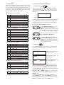
for TOSHIBA
PRODUCT INSTRUCTIONS
Specification
Number
INSTRUCTIONS
5240
1.1 GENERAL DESCRIPTION
Catalog
Section
The VLC485 is a pan/tilt controller that ties together the major
elements of an integrated system and provides a single human
interface for the system. As such, the VLC485 can control pan/tilt
units, interface to multiplexers, and communicate with a personal
computer for computer-controlled operation.
2C
MODEL: Pan/Tilt Controller
VLC485
A NOTE BEFORE BEGINNING
Each camera controlled by the VLC485 must have a unique
address. The default address for most cameras is "1". See the
instructions for your camera for steps to change the address.
1.0 TABLE OF CONTENTS
1.0 Table of Contents
1.1 General Description
1.2 Specification
1.3 Included Accessories
1.4 Location and Description of Controls
1.5 Location of Connectors
1.6 Connections
2.0 Control of Basic Functions
2.1 Camera SelectionPan/Tilt Movement
2.2 Camera Zoom/ Focus/Iris Functions
2.3 Pan/Tilt Movement
2.4 Presets
2.5 Autotour
2.6 Sequencing
2.7 Alarms
3.0 Menu Items
3.1 Dome Selection Type
3.2 Multiplexer Type
3.3 Preset Lockout
3.4 Autotour Dwell
3.5 Beep Enable
3.6 Sequence
3.7 Sequence Dwell
3.8 Alarms
3.9 Pass Code
4.0 PC Port
4.1 PC Port Commands
4.2 General Command Message Format
4.3 Motion Command Messages
4.4 Preset and Dome Parameter Messages
4.5 Controller Parameter Messages
4.6 Custom Controller LCD Messages
Page No.
1
1
1
2
2
2
3
3
3
3
3
3
4
4
4
4
4
4
4
5
5
5
6
6
6
6
6
6
6
7
7
7
The LCD is used to display current status as well as to provide a
menu system for setting operational parameters.
The VLC485 is designed for desktop operation; all connectors are
located in the rear of the unit so that all cables can be routed from
the back of the unit.
1.2 SPECIFICATIONS
Power Source
5v DC 250 ma.
Data Connections
4-pin compression connector:
RS485/422 Pan/Tilt control network.
9-pin d-sub connector: RS232 multiplexer port.
9-pin d-sub connector: RS232
external serial communications
port.
Pan/Tilt Control
Maximum number of pan/tilts: 99.
Protocols: Videolarm, Sensormatic,
Pelco, and Kalatel.
Manual control: pan, tilt via joystick.
Speed: Variable.
Presets: go to, set, clear.
Autotour (Videolarm protocol): on,
off, set dwell, set speed.
Camera Control
Manual control: Zoom, focus, iris.
Auto: focus, iris (where supported
by camera).
Multiplexer Control
Protocols: TBD.
Number of channels: up to 32.
Alarms
Eight external alarm inputs and
one relay contact alarm output.
Configuration
Menu driven, access controlled
by optional passcode.
Display
LCD, 20 character x 2 lines.
External Serial
Communications Port
9600 baud, 8 bits, 1 start, 1stop,
no parity
Protocols: Videolarm, Pelco P.
Operating Environment
Temperature: 0˚ C – 50˚ C.
Humidity: 90% maximum (noncondensing).
Altitude: 10,000 ft. maximum.
2525 Park Central Blvd. • Decatur, GA 30035 • (770) 987-7550 • 800-554-1124 • Fax 800-826-0366 • www.videolarm.com
1.3 INCLUDED ACCESSORIES
(1) Control Output Connector
(1) Alarm Output Connector
(1) 5 VDC AC Adapter
1.4 LOCATION AND DESCRIPTION OF CONTROLS
Auxiliary
Function
(for future use) (for future use)
Sequence
Alarm
1, 2, 3...
F
Auto Tour
Camera
1
2
3
Zoom Out / Zoom In
Monitor
4
5
6
Focus Far / Focus Near
Presets
7
8
9
Iris Close / Iris Open
Menu
*
0
#
(for future use)
1.5 LOCATION OF INPUT/OUTPUT CONNECTORS
RS-485 Control
Alarm Inputs
5VDC
Power Input
R R T T
A B A B
OUT
PC Port
IN
N N
CO C C 8 7 6 5 4 3 2 1
MUX Port
Alarm Outputs
-2-
2.0 CONTROL OF THE BASIC FUNCTIONS
1.6 CONNECTIONS
There are five connectors on the VLC485 Controller. These connectors are a 9-pin connector for RS232 connections to a PC, a 9-pin
connector for RS232 connections to an external device, a 4-pin
compression connector for the RS485/422 pan/tilt network, and a
9-pin terminal for alarm inputs. The RS232 ports are configured as
data communication equipment (DCE) ports.
2.1 CAMERA SELECTION
In order to view or control a camera and the pan/tilt, the camera
must be selected. To do this, enter the camera number using the
keypad and press the CAMERA button. The LCD should show the
following:
1. Multiplexer Connector: (Not Supplied)
Pin
1
2
3
4
5
6
7
8
9
CAM 01
DCE Function
Transmit data (to main multiplexer)
Receive data (from main multiplexer)
2.2 PAN/TILT MOVEMENT
Pan/tilt movement is controlled by the joystick. If the selected pan/tilt
supports variable speed operation the speed of the pan/tilt will be
increased as the joystick is moved away from the center position.
Signal Ground
Signal Ground
Transmit data (to expansion multiplexer)
2.3 CAMERA ZOOM/FOCUS/IRIS FUNCTIONS
Use the ZOOM OUT/ZOOM IN key to operate
the zoom function of a selected camera.
NOTE: Whenever the camera zoom is changed,
the controller places the camera into auto focus
and auto iris mode if these modes are available.
2. PC Connector: (Not Supplied)
Pin
1
2
3
4
5
6
7
8
9
DCE Function
Transmit (to PC)
Receive (from PC)
If you want to focus a camera manually press
the FOCUS FAR/FOCUS NEAR keys.
Signal Ground
The IRIS CLOSED/IRIS OPEN keys will allow
you to change the iris setting of a camera.
NOTE: Some cameras provide continuous iris
function as the keys are held down; others may
require repetitive key presses.
3. Multiplexer Connector: (Included)
Pin
1
2
3
4
5
6
7
8
9
10
11
12
2.4 PRESETS
Function
Alarm 1 input
Alarm 2 input
Alarm 3 input
Alarm 4 input
Alarm 5 input
Alarm 6 input
Alarm 7 input
Alarm 8 input
Alarm Common
Alarm Output NO Contact
Alarm Output NO Contact
Alarm Output Common
For pan/tilts that support presets, up to 99 can be programmed on
the VLC485. To LOCKOUT presets, see Menu Section, Item 3.3.
TO SET A PRESET:
Function
TXA to pan/tilts
TXB to pan/tilts
RXA from pan/tilts
RXB from pan/tilts
Center Contact
Outside Contact
CAM 01
Enter the preset number (1 - 99)
on the keyboard.
CAM 01
PRESET 07
Press the POUND (#) key, then
press the PRESETS key.
For errors or to change the preset number repeat the procedure.
TO GO TO A PRESET: Select the camera as noted above. Enter
the preset number. Press the PRESET button and the camera will
go to the preset location. The LCD will show the camera number and
preset number as shown above.
5. Power 5VDC: (Included)
1
2
Select a camera and position it
to the desired location.
07
4. Pan/Tilt Network Connector: (Included)
Pin
1
2
3
4
CAM 01
+ (Plus)
- (Minus)
TO CLEAR A SINGLE PRESET: Select the camera as noted above.
Enter the preset number, press the STAR (*) key, then press the
PRESET button.
TO CLEAR ALL PRESETS: Select the camera as noted above.
Press the STAR (*) key, then press the PRESET button. A "?" will
appear. Press PRESET again and all presets for that camera will be
cleared. To cancel this function, press the STAR (*) key.
-3-
2.5 AUTO TOUR
3.1 DOME TYPE SELECTION
The VLC485 can accommodate pan/tilts that support Auto tour
functions. To start a pan/tilt on an Autotour, press the AUTO TOUR
button. For Toshiba domes, enter 70 and press the PRESETbutton.
CAM 01
Videolarm designed the VLC485 to support RS485/422 control protocols from a number of manufacturers. Dome type selection is independent of the camera position, which means that you can build a
system using multiple dome types. For Toshiba domes, select Pelco P.
AUTO
TO CHANGE CAMERA PROTOCOL:
To stop the Auto tour, press the AUTO TOUR button or move the
joystick. To SET AUTO TOUR DWELL, see Menu Section, Item 3.4.
2.6 SEQUENCING
CAM 04
1, 2, 3...
Press the MENU button. Enter
password if necessary.
In conjunction with a multiplexer the VLC485 will sequence through
a predetermined list of up to 16 cameras. To start sequencing press
the SEQUENCE button. The camera number will show the currently
active camera in the sequence and a camera select command for the
camera will be sent to the multiplexer.
CAM 01
Select a camera.
DOME TYPE
VIDEOLARM
DOME TYPE
SEQUENCING
SENSORMATIC
The current pan/tilt type will display. To select a different type
press the STAR (*) key until the
desired type is displayed.
Press the POUND (#) key
to enter the selection. Press
MENU to exit the menu mode.
To stop the sequence, press the SEQUENCE button or move the
joystick. For SEQUENCING OPTIONS, see Menu Section, Item 3.6.
3.2 MULTIPLEXER SELECTION
2.7 ALARMS
The VLC485 can also support multiplexers from a number of manufacturers to allow the unit to control even more cameras.
Up to 8 alarms can be programmed into the VLC485. When an alarm
occurs, the ALARM message shows in the display window.
TO SELECT A MULTIPLEXER TYPE:
CAM 06
Press the MENU button. Enter
password if necessary.
ALARM 07
MUX TYPE
The VLC485 sends a command to that camera telling it to go to the
preset point. When an alarm occurs at that position, the VLC485 will
display that camera and alarm. A beep also sounds from the unit.
ATV
To clear an alarm, press the ALARM button.
HITRON
DOME TYPE
3.0 CONTROL OF THE MENU ITEMS
3.1 CAMERA SELECTION
Additional functions are available through the menu on the VLC485.
To access the menu, press the MENU button.
To scroll through the various menu items press the STAR (#) key on
the key pad. When you're finished with your selections and want to
leave menu mode, simply press the MENU button again.
Access to the menu can be protected with a 4-digit password. See
3.9 PASSCODE to enable the password function.
Use the POUND (#) key to
scroll to the Multiplexer Type.
The current type will be displayed.
Press the STAR (*) key until the
desired type is displayed. Press
the POUND (#) key to select.
Press MENU to exit the menu
mode.
The VLC485 can connect to one main multiplexer and an additional
expansion multiplexer if this feature is supported by the multiplexer.
The main multiplexer is used to handle camera numbers 1 through
16 while the expansion multiplexer is used to handle camera numbers
17 through 32.
3.3 PRESET LOCKOUT
TO LOCKOUT THE ABILITY TO SET OR CLEAR PRESETS:
Press the MENU button. Enter
password if necessary.
Here are the selectable settings in the menu mode:
PRESET ENABLE
1) Dome Type Selection
2) Multiplexer Selection
3) Preset Enable
4) Autotour Dwell
5) Set Beep
6) Sequence of Camera (when used with a multiplexer)
7) Sequence Dwell
8) Alarm Set
9) Pass Code Enable
YES
PRESET ENABLE
NO
-4-
Use the POUND (#) key to
scroll to Preset Enable. The current setting will be displayed.
Press the STAR (*) key to
change the setting. Press the
POUND (#) key to select. Press
MENU to exit the menu mode.
3.4 AUTO TOUR DWELL
3.6.2 TO ADD A CAMERA TO A SEQUENCE
Auto tour Dwell defines how long the pan/tilt will stay at each preset
in the auto tour. This parameter is preset in the pan/tilt, but the
VLC485 allows you to override that setting via the menu if this feature
is supported by the pan/tilt. A range from 3 to 99 seconds can be set.
A sequence may contain up to 16 camera entries. If you have not
filled a sequence and would like to add cameras to it, do the following.
Press the MENU button. Enter
password if necessary. Use the
POUND (#) key to scroll to
Sequence.
Press the MENU button. Enter
password if necessary.
SET AUTOTOUR DWELL:
SET AUTOTOUR DWELL:
30
Use the POUND (#) key to
scroll to Set Auto tour Dwell
mode.
SEQUENCE - ADD CAM:
Use the keypad to enter the
desired dwell time. Press the
POUND (#) key to select. Press
MENU to exit the menu mode.
SEQUENCE - ADD CAM:
21
3.5 BEEP ENABLE
1, 2, 3...
Also, if enabled, a brief beep will sound when each button is pressed.
To prevent damage to the joy stick, a beep sound is activated whenever the joystick is at its maximum position. This function can be
disabled in the Menu Mode.
Press the MENU button. Enter
password if necessary.
YES
NO
Press the MENU button. Enter
password if necessary. Use the
POUND (#) key to scroll to
Sequence.
1, 2, 3...
3.6 SEQUENCING
SEQUENCE - ADD CAM:
Sequencing allows you to view up to 16 cameras in a specific order.
The sequence can be set and reviewed and cameras can be added
or subtracted using the Menu Mode.
17
Press the MENU button. Enter
password if necessary.
SEQUENCE - ADD CAM:
05
SEQUENCE - ADD CAM:
08
Use the POUND (#) key to
scroll to Sequence. If a
sequence is already set the first
camera in the sequence will be
displayed.
1, 2, 3...
3.6.1 TO REVIEW A SEQUENCE
Press the MENU button. Enter
password if necessary. Use the
POUND (#) key to scroll to
Sequence.
1, 2, 3...
Press the STAR (*) key, then
press the SEQUENCE button.
At that point another blank
space will appear. You may
add another camera to the
sequence at this time (up to
a total of 16), or press the
SEQUENCE button again to
review your entries.
You may change any entry in a sequence at any time. Remember
that these changes overwrite your existing sequence.
Press the STAR (*) key to
change the setting. Press the
POUND (#) key to select. Press
MENU to exit the menu mode.
BEEP ENABLE
To add a camera to the existing
sequence enter the camera
number on the key pad.
3.6.3 TO CHANGE A CAMERA IN A SEQUENCE
Use the POUND (#) key to
scroll to Beep Enable. The current setting will be displayed.
BEEP ENABLE
A blank space will appear after
the last camera of the current
sequence.
You can review the existing
sequence by pressing the
SEQUENCE button. Each time
you press it the next camera
will be displayed. When a blank
appears, that will be the end of
the sequence.
-5-
Usiing the SEQUENCE button,
scroll through the sequence
until you reach the camera you
want to change.
Using the keypad, enter the
number of the camera you want
to use.
Press the STAR (*) key, then
press the SEQUENCE button.
The number of the next camerea in the sequence will
appear. Press the SEQUENCE
button again to continue to
review your entries.
3.6.4 TO CLEAR THE SEQUENCE
Press the MENU button. Enter
password if necessary. Use the
POUND (#) key to scroll to
Sequence.
SEQUENCE - ADD CAM:
Using the key pad, enter 00.
Press the STAR (*) key, then
press the SEQUENCE button.
The sequence will be blank.
3.7 SEQUENCE DWELL
4.0 PC PORT
The sequence dwell interval defines how long the camera will stay
active in the sequence. The factory default dwell time is 3 seconds,
but this may be changed to any time between 1 and 99 seconds.
The VLC485 uses the PC port to communicate with the serial communications port of a PC or modem. The PC or other connected
device uses a protocol to control either the VLC485 or other devices
connected to the VLC485, such as the pan/tilt units. In addition, all
controller activities, including joystick movements, are transmitted to
the PC port. This enables the controller to become a “peripheral” to
a PC and act as the man/machine interface for a system. Following
are the VLC485 protocols.
Press the MENU button. Enter
password if necessary.
SEQUENCE - ADD CAM:
03
SEQUENCE - ADD CAM:
03
Use the POUND (#) key to
scroll to Set Sequence Dwell.
The current dwell time will be
displayed.
4.1 PC PORT COMMANDS
Using the key pad, enter the
new dwell time. Press the STAR
(*) key to set the time. Press
MENU to exit the menu mode.
3.8 CONTROLLER ALARMS
VLC485 RS232 COMMUNICATION PROTOCOL
(NOTE: This applies to software version 2.50 and later)
These messages are used to send and receive control messages
from the PC.
4.2 GENERAL COMMAND MESSAGE FORMAT
The VLC485 responds to alarms from its alarm inputs. When an
alarm occurs, a “go to preset” command will be sent to a predetermined pan/tilt. For example, alarm 3 may select preset 23 of
camera 7 to be displayed. The preset number and pan/tilt number are
preselected by using the alarm setup function.
Data is transmitted at 9600 baud, 1 start bit, 1 stop bit, 8 data bits
(lsb first), no parity.
Press the MENU button. Enter
password if necessary.
ALARM 1
CAM 01
PRESET 03
ALARM 1
When an alarm occurs, ALARM
appears onscreen. The alarm
message can only be cleared by
pressing the ALARM button.
1234
Start character "~"
Data
All data characters
n+1
0x0d
"Carriage return" character
n+2
0x0a
"Line feed" character
FUNCTION
D
BYTE #2 BYTE #3
T/R
"1"
"0" - "?"
T/R
"r"
"0" - "?"
Pan stop
T/R
"P"
"S"
Tilt up at
T/R
"u"
"0" - "?"
speed "x"
Pan right at
speed "x"
Tilt down at
Use the POUND (#) key to
scroll to Passcode Enable.
On selecting YES, the default
passcode will display. Change
by entering a new 4-digit code
on the key pad. Press STAR (*), POUND (#) or the MENU button to
enable the passcode and automatically exit the menu mode.
-6-
Pan left at speed index
Pan right at speed
index 0 - 15
Tilt up at speed index
0 - 15
T/R
"d"
"0" - "?"
Tilt stop
T/R
"T"
"S"
Zoom in
T/R
"Z"
"I"
Zoom out
T/R
"Z"
"O"
Zoom in (Telephoto)
Zoom stop
T/R
"Z"
"S"
Zoom out (Wide angle)
Focus near
T/R
"F"
"N"
Focus far
T/R
"F"
"F"
Focus on nearby
Focus stop
T/R
"F"
"S"
objects
Iris open
T/R
"I"
"O"
Focus on distant object
Iris close
T/R
"I"
"C"
Iris stop
T/R
"I"
"S"
speed "x"
Press STAR (*) to toggle
between YES to enable and NO
to disable. Pressthe POUND (#)
key to enable the selection.
DESCRIPTION
0 - 15
speed "x"
NO
SET PASSCODE:
0x7e
2-n
Pan left at
Press the MENU button.
YES
1
These commands control the basic motion of the pan/tilt platform
and the lens movement of the camera system. The messages all
comprise 5 bytes; the Data is contained in bytes 2 and 3 as described
in the following table. Messages that are transmitted from the controller are indicated by a “T” in the direction column, D; messages that
are received and processed by the controller are indicated by a “R”
in the direction column.
You can protect your controller from unauthorized alterations by
enabling the passcode function. This means that the menu cannot be
accessed without the proper 4-digit. The VLC485 is factory set with
PASSCODE disabled. To enable and set the passcode:
PASSCODE ENABLE:
DESCRIPTION
4.3 MOTION COMMAND MESSAGES
3.9 PASSCODE ENABLE/SET/CHANGE
PASSCODE ENABLE:
DATA
are 8-bit characters
To set up an alarm, enter the
menu mode and scroll down to
the “ALARM:” entry. Press the
STAR (*) button to scroll to the desired alarm number. The display
will show the camera number and preset associated with the alarm.
Use the keypad to enter or change the camera number and press
the CAMERA button. Use the keypad to enter or change the preset
number and press the PRESET button. Press STAR (*) to select
another alarm, or exit the menu by pressing the MENU button.
CAM 03
BYTE
Tilt down at speed
index 0 - 15
4.4 PRESET AND DOME PARAMETER MESSAGES
4.6 CUSTOM CONTROLLER LCD MESSAGES
These commands control the position presets and some of the operational parameters of the pan/tilt platform. These messages all comprise 5 bytes; the Data is contained in bytes 2 and 3 as described in
the following table. Messages that are transmitted from the controller
are indicated by a “T” in the direction column, D; messages that are
received and processed by the controller are indicated by an “R” in
the direction column.
If needed, you can write custom messages from your PC for display
on the VLC485. Any information goes only to the controller LCD.
FUNCTION
D
Goto preset
T/R
BYTE #2 BYTE #3
"H"
position pre-
0x01 -
LCD CAPTURE MESSAGE
The display character string message will override any messages
displaying on the VLC485, in essence "capturing" the display.
DESCRIPTION
BYTE
Goto preset position
0x3f
DATA
1
"~"
Start character
2
"D"
"D" indicates a character string is to
3
"0" or "1"
sets 1 - 63
Store preset
be displayed
T/R
"P"
position pre-
0x01 -
Store preset position
0x3f
T/R
"P"
"C"
sets
Toggle auto
T/R
"L"
"a"
tour
Set dwell
"t"
"0" - "9"
time
This is the message string to be
4 - 23
ASCII characters
memory
24
0x0d
"Carriage return" character
Toggles autotour opera-
25
0x0a
"Line feed" character (optional,
Clears all presets from
displayed
tion on and off
T/R
This is the LCD line number, either
0 or 1
sets 1 - 63
Clear pre-
DESCRIPTION
ignored)
Set dwell time in auto-
LCD RELEASE MESSAGE
tour mode to 1 - 10 seconds
The display release message will clear the LCD display and allow its
use by the VLC485.
4.5 CONTROLLER PARAMETER MESSAGES
BYTE
These messages contain information about the controller status.
These messages all comprise 5 bytes; the Data is contained in
bytes 2 and 3 as described in the following table. Messages that
are transmitted from the controller are indicated by a “T” in the direction column, D; messages that are received and processed by the
controller are indicated by a “R” in the direction column.
FUNCTION
Camera
D
T/R
BYTE #2 BYTE #3
"C"
select
Monitor
T/R
"M"
select
Sequence
Current camera
0x63
number
0x01 -
Current monitor
0x63
number
T
"S"
0x00
Sequence off
T
"S"
0x01
Sequence on
Alarm active T
"A"
0x01 -
Active alarm number.
0x0a
Alarm has been
status
detected on alarm input
Alarm kill
T/R
Aux function T
"A"
"K"
Acknowledge all alarms
"X"
0x01 -
Toggles aux 1 output
aux01 -
0x6c
aux99
Information
T
"B"
"B"
key
Information key
pressed
Menu active
T
"M"
"A"
Menu inac-
T
"M"
"I"
Contoller is in the menu
mode
tive
"~"
2
"D"
Start character
3
"R"
4
0x0d
"Carriage return" character
5
0x0a
"Line feed" character (optional,
A message sent to the VLC485 can be cleared at the controller by
pressing the Information button.
status
Sequence
1
DESCRIPTION
ignored)
DESCRIPTION
0x01 -
DATA
Controller is not in the
menu mode
-7-
The VLC485 can be used in as a stand-alone unit or as part of a
system. As part of a system, the unit may be used with another
VLC485 or with a PC. Below are diagrams for these types of systems.
Typical application
Video
RS485
Control
PC Port
Controller
Mux Port
Multiplexer
Controller
Call Out
Monitor
Main
Monitor
PC System
Video
RS485
Control
PC
PC Port
Mux Port
Multiplexer
Controller
Call Out
Monitor
-8-
Main
Monitor
IMPORTANT SAFEGUARDS
1. Read Instructions - All the safety and operating instructions
should be read before the unit is operated.
2. Retain Instructions - The safety and operating instructions
should be retained for future reference.
3. Heed Warnings - All warnings on the unit and in the operating
instructions should be adhered to.
4. Follow Instructions - All operating and user instructions
should be followed.
5. Electrical Connections - Only a qualified electrician should
make electrical connections.
6. Attachments - Do not use attachments not recommended by the
product manufacturer as they may cause hazards.
7. Cable Runs - All cable runs must be within permissible
distance.
8. Mounting - This unit must be properly and securely mounted
to a supporting structure capable of sustaining the weight of
the unit. Accordingly:
a. The installation should be made by a qualified installer.
b. The installation should be in compliance with local codes.
c. Care should be exercised to select suitable hardware to
install the unit, taking into account both the composition of
the mounting surface and the weight of the unit. Be sure to
periodically examine the unit and the supporting structure to
make sure that the integrity of the installation is intact.
Failure to comply with the foregoing could result in the
unit separating from the support structure and falling, with
resultant damages or injury to anyone or anything struck
by the falling unit.
ONE-YEAR LIMITED WARRANTY
Videolarm, Incorporated warrants that products sold hereunder
shall be fit for the ordinary purpose for which said products
are intended and shall be free from defects in material and
workmanship for a period of one year from date of sale to buyer.
Note that all electrical components will be warranted for a period
of 1 year from date of sale to buyer. Videolarm makes no
other warranty of any kind with respect to this product, whether
expressed or implied, including, without limitation, the implied
warranty of fitness for a particular purpose.
In the event of a breach of the above warranty, Videolarm shall,
at its option, repair or replace said product. This is Videolarm's
sole obligation under this warranty. In no event shall Videolarm
be liable for any incidental or consequential damages, as defined
in section 2-715 of the Uniform Commercial Code by a breach
of this warranty.
Videolarm shall repair or replace defective products upon shipment
of products prepaid to Videolarm, Inc., 2525 Park Central Blvd.,
Decatur, GA 30035.
Repairs made necessary by reason of accident, misuse or normal
wear shall be charged at Videolarm's standard rate. This warranty
gives you specific legal rights, and you may also have other rights
which vary from state to state.
-9-
SAFETY PRECAUTIONS
CAUTION
RISK OF ELECTRIC
SHOCK!
!
CAUTION: TO REDUCE THE RISK OF ELECTRICAL
SHOCK, DO NOT OPEN COVER.
NO USER SERVICEABLE PARTS INSIDE.
REFER SERVICING TO QUALIFIED SERVICE PERSONNEL.
The lightning flash with an arrowhead symbol,
within an equilateral triangle, is intended to alert the
user to the presence of non-insulated "dangerous
voltage" within the product's enclosure that may
be of sufficient magnitude to constitute a risk of
electric shock to persons.
!
The exclamation point within an equilateral triangle
is intended to alert the user to presence of important
operating and maintenance (servicing) instructions
in the literature accompanying the appliance.
UNPACKING
Unpack carefully. Electronic components can be damaged if
improperly handled or dropped. If an item appears to have
been damaged in shipment, replace it properly in its carton
and notify the shipper.
Be sure to save:
1. The shipping carton and packaging material. They are the
safest material in which to make future shipments of the
equipment.
2. These Installation and Operating Instructions.
SERVICE
If the unit ever needs repair service, the customer should contact
Videolarm (1-800-554-1124) for authorization to return and
shipping instructions.
TECHNICAL SUPPORT
If technical support is needed, Videolarm has set-up a 24 hour
technical support line for their customers.
24 HOUR TECHNICAL SUPPORT
1-800-554-1124