1
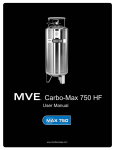
BULK CARBON DIOXIDE SUPPLY SYSTEMS
MVE MODELS CARBO-MIZER 450 & 750
Place this chapter in the Beverage section of
the Equipment Manual.
MANUFACTURED
FOR
McDONALD’S™
BY
Chart Industries, Inc.
3505 COUNTY ROAD 42 WEST
BURNSVILLE, MN 55306-3803
TELEPHONE: 952-882-5000
FAX: 952-882-5185
TABLE OF CONTENTS
SAFETY PRECAUTIONS
Page 1
GENERAL DESCRIPTION
Page 2
OPERATION FACTS AND PROCEDURES
Page 5
MCDONALD’S BEVERAGE SYSTEM LAYOUT
Page 6
CARBO-MIZER 450 / 750 VESSEL SPECIFICATIONS
Page 7
VESSEL PARTS IDENTIFICATION & FUNCTION
Page 8
FILL BOX PARTS & HOSE IDENTIFICATION
Page 11
PORTABLE INSTALLATION COMPONENTS
Page 12
TROUBLESHOOTING GUIDE
Page 13
SERVICE AND PARTS
Page 17
WARRANTY
Page 18
VESSEL FLOW SCHEMATIC
Page 19
© 2003 CHART Industries, Inc.
All Rights Reserved
Copyright: Chart Industries, Inc., May 2003
Revision 1
May 2003
Printed in USA
CHART P/N 11817059
Copyright: Chart Industries, Inc., May 2003
User Manual
McDONALD’S
Carbo-Mizer 450 • Carbo-Mizer 750
Copyright: Chart Industries, Inc., May 2003
Copyright: Chart Industries, Inc., May 2003
Safety Precautions
pressure vessels. They should be familiar with all
pertinent safety procedures.
IMPORTANT SAFETY PRECAUTIONS
The type of vessel described in this manual
holds and dispenses carbon dioxide (CO2)
gas under pressure. All persons using this
equipment must read and understand the
operation and safety information contained in
this manual.
FIRST AID AND EMERGENCY ACTION
If inhaled:
•
•
•
•
WARNINGS
CO2 gas is a colorless, odorless, tasteless gas that
displaces oxygen and will not support life. The gas
is difficult to detect without special equipment.
Avoid breathing or contacting CO2 in gas, liquid
or solid form. Exposure to concentrations of less
than 5% for less than 15 minutes can cause physical
symptoms including unconsciousness, injuries or death.
Even low concentrations of CO2 can cause:
In case of frostbite:
• End exposure immediately.
• Do not rub or pour water on the affected area.
• Get immediate medical attention.
Rescue:
• Do not attempt a rescue in areas of high CO2
concentrations without proper life-support or
rescue equipment. (Avoid being the next victim.)
• Thoroughly ventilate areas of possible high
CO2 concentration before entering them.
• Dizziness, headaches, nausea or disorientation
• Increased respiration or heart rate
• Shortness of breath or rapid suffocation.
CO2 is heavier than air and can collect in low areas
such as basements, stairwells, and confined spaces.
Avoid entry into areas where CO2 leaks or high
concentrations of CO2 are suspected. Enter those areas with
caution only after they have been thoroughly ventilated.
In case of spills or leaks:
• Evacuate all personnel immediately from
affected areas.
• Thoroughly ventilate the area of the spill or
leak before entering.
• CO2 is heavier than air. It displaces oxygen
and will collect in low or confined areas.
Whenever the vessel is inside a building it’s safety
relief circuit must be connected to an outdoor vent
typically in the fill box. The fill box and/or vent
must never be located in or above any belowground spaces or stairwells. The vessel must not
block emergency exits, aisles, fire suppression
equipment or utility boxes or accesses. CO2 lines
or hoses must be located away from traffic areas
and heat sources and must be protected from
potential causes of damage. All connections,
lines, and components must be leak-free.
FOR MORE INFORMATION CONTACT:
Local CO2 supplier
or
Compressed Gas Association
725 Jefferson Davis Highway, Suite 1004
Arlington, VA 22202-4100 USA
Telephone: (703) 412-0900
FAX: (703) 412-0900
This equipment should be installed and serviced
only by professional personnel who are qualified
to work with CO2 and the mini-bulk liquid CO2
Copyright: Chart Industries, Inc., May 2003
Move to fresh air immediately.
If not breathing, give artificial respiration.
If breathing is difficult, give oxygen.
Get immediate medical attention.
1
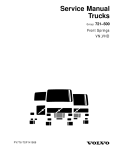
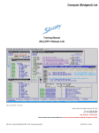
General Description
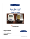
System Overview
The Carbo-Mizer carbon dioxide (CO2) system
for McDonald’s restaurants is designed for lowpressure storage and supply of carbon dioxide gas
for beverage carbonation. The system consists of
three primary elements: the CO2 storage vessel, an
outdoor fill box, and fill and vent lines.
Syrup
Gas Supply
Vent Circuit
Fill Circuit
Shut-Down
Circuit
Storage Vessel
The vessel is the first of the three primary elements
in the Carbo-Mizer storage system. It consists
of an inner vessel and an outer vessel, much like
a ThermosTM bottle. The space between the two
vessels contains a nearly perfect vacuum and a
special insulation. The vacuum and insulation
minimize the entry of unwanted heat into the
liquid CO2 stored in the inner vessel. When CO2
gas is needed it is withdrawn from the top (gas
space) of the inner vessel and dispensed to the
beverage system or other use point.
Carbonator
Gas Supply
Pressure
Building Circuit
Vessel Plumbing
Plumbing components on the vessel perform
five functions:
• Liquid CO2 fill
• Gas supply (Gas Delivery)
• Pressure control (Pressure Building)
• Safety (Vent/Relief)
• Pressure and contents measurement (Gauges)
The fill circuit allows liquid CO2 to be transferred
into the vessel during the delivery process. The gas
supply circuit dispenses CO2 gas to the beverage
and syrup systems. A pressure control circuit
maintains the internal vessel pressure needed to
supply CO2. The vent/relief circuit allows excess
pressure to safely exit the vessel and the building.
A contents and pressure gauge indicate the status of
the CO2 inside the vessel.
Vaporizer Coil
6” (15.2 cm) Uni-body legs
2
Patented Impurity
Removal System
(Collection Ring on
Mizer 450 only)
Copyright: Chart Industries, Inc., May 2003
by sensing the internal vessel pressure. When that
pressure drops below the regulator’s set point (factory
set at 140 psi), the regulator opens allowing liquid
CO2 to flow into the vaporizer where it transforms to
gas and re-pressurizes the vessel. When the internal
pressure reaches the regulator’s set point, the
regulator closes and the flow of liquid CO2 stops.
Fill Circuit
The stationary fill circuit consists of a brass fill
fitting in the fill box, a fill hose, and a valve on
the vessel. Liquid CO2 is transferred into the
vessel through the brass fill box fitting and the
fill hose. The shut-off valve on the vessel’s fill
port allows service to be performed on the fillbox / fill-line segment of the fill circuit without
emptying the vessel. A portable vessel’s fill
circuit consists of a brass fill fitting and bracket
secured to the top of the vessel.
During the pressure building process cold liquid
carbon dioxide flows through a vaporizer coil that
is attached to the inside wall of the outer vessel.
This cools the outside of the vessel and causes a
condensation or frost ring to form near the bottom
of the vessel. The appearance of a frost ring is
normal when CO2 is being used . However, if
frost is present after some time when no CO2 gas
has been used, such as in the morning before the
start of operations, this may indicate a CO2 leak in
a line or the beverage or other use-point system.
Gas Use Circuit
The gas-use circuit supplies gas to the carbonator
and syrup systems. CO2 gas is withdrawn from
the gas space above the liquid CO2 that is stored in
the vessel. When demanded at either use point,
CO2 gas passes through the shut-down ciecuit
valve and into the respective final line regulator.
Safety Vent Circuit
The final line regulators control gas flow to the
beverage or syrup systems. The factory setting
on the carbonator gas supply regulator is 90 psi
but the pressure may be adjusted to suit the needs
of the application. This regulator is commonly
set between 90 psi and 115 psi for soft drinks.
Secondary pressure regulators may be added
‘downstream’ for applications such as bag-in-thebox or diet systems. The syrup gas use regulator
is set at 65 psi for the syrup system. Consult with
the use-point equipment manufacturer for the
correct regulator and pressure setting.
The inner pressure vessel of this storage system
is designed to meet or exceed the ASME Section
VIII, Division 1 pressure vessel code. The code
dictates that the vessel be protected against excess
pressure by a safety relief valve. Chart uses two
safety relief valves for added safety. The vessel’s
safety circuit is comprised of an ASME relief
valve set at 300 psig and an additional relief valve
set at 450 psig. The relief valves must always be
vented outdoors by a vent tube, usually through
the fill box, to prevent potential concentration of
CO2 within the building. The 300 psig relief valve
may open during CO2 deliveries or when CO2 is
not being used regularly.
Pressure Control Circuit
The pressure control circuit, also called the
“pressure building” or “PB” circuit, maintains the
internal operating pressure of the vessel. Adequate
vessel pressure is needed for supplying CO2 gas and
for preventing the stored liquid carbon dioxide from
changing to ‘dry ice,’ the solid form of CO2.
Pressure And Contents Gauges
The vessel pressure gauge measures the pressure
in the top (gas space) of the inner vessel.
This pressure can normally range between 140 psig
and 300 psig but the typical vessel operating
pressure is 140 to 165 psig.
The pressure building circuit activates to rebuild
internal vessel pressure as gas is drawn from the
vessel and its pressure drops below a set level.
A regulator controls the pressure building process
Copyright: Chart Industries, Inc., May 2003
The vessel contents gauge measures the
approximate level of CO2 liquid in the vessel.
The movement of a magnetic rod “floating” in
3
the liquid CO2 causes the needle on the contents
gauge to move as the level of liquid CO2 in the
vessel changes.
The Bulk CO2 Supplier
The bulk CO2 supplier is also an important part of
the system. Most CO2 suppliers not only provide
timely delivery of CO2 but also install and service
the system. For service, parts, information,
emergency CO2 delivery, or other CO2 related
assistance, contact the local Chart authorized
CO2 supplier. A place has been designated on
page 17 of this manual to record the name and
phone number of the CO2 supplier and other
important service contacts.
NOTE: Because the float-rod does not actually
float on the surface of the liquid CO2 it does not
provide a precise measurement of liquid CO2 level.
CO2 Fill Box
The stainless steel CO2 fill box is the second major
element in a typical bulk CO2 storage system.
The purpose of the fill box is to provide a
convenient point to fill the storage vessel, to make
connections for syrup delivery, and to vent excess
pressure from the vessel out of the building.
The fill box has a brass fill fitting, a connection for
the safety relief vent circuit, a safety snap connection
point, and a lockable door. Two standard types of
fill boxes are available; a surface-mount model and a
flush-mount model.
Fill boxes must be mounted outside the building
where they are easily accessible to the CO2
supplier and where they can safely vent excess
CO2 pressure outdoors. When a vessel is used as a
portable system, a vessel-mounted brass fill fitting
and an alternative safety relief vent line are used
instead of the fill box.
Fill Hose And Vent Line
The third major element of a stationary bulk CO2
system is comprised of a fill hose and vent line.
These lines join the CO2 storage vessel with the
outdoor fill box. The fill hose, constructed with FDA
compliant materials, is a pressure rated line that
connects the brass fill fitting in the fill box to the fill
circuit on the vessel. The vent line is as important as
any component in the system. It connects the safety
relief valves on the vessel to either the outdoor fill
box or to an alternative outdoor vent tube.
NOTE: Whether used as stationary or as portable,
the vessel must always be connected to an outdoor
vent line when it contains CO2 and is indoors.
4
Copyright: Chart Industries, Inc., May 2003
Operation Facts and Procedures
Operation Facts
General Operating Procedures
1. A vessel’s normal internal operating pressure
(43) is between 140 psi and 165 psi.
1. Every day before starting operations and CO2
use check for:
• CO2 leaks (See “Safety”.)
• Pressure readings (43) & (46) x 2
• CO2 contents (22)
• Abnormal frost or condensation
• Anything unusual.
2. Vessel pressure can be as high as 300 psi after
a delivery, but returns to its normal operating
pressure after a day or two of normal CO2 use.
3. The carbonator gas supply pressure (45) is
normally between 90 psi and 115 psi.
2. Always use caution when working with CO2.
Read and understand the “Safety” section of
this manual.
4. The syrup gas supply pressure (44) is
normally 65 psi.
5. Frost or condensation on the vessel is normal
during periods of CO2 use.
3. The Carbo system does not require adjustment
under normal operating conditions.
6. Frost or condensation on the vessel before
starting the daily use of CO2 is a sign of a CO2
leak. Have the leak fixed.
4. Check the vessel daily before using CO2.
See ‘operation fact’ number 10.
5. In an emergency the flow of CO2 from or
through the Carbo-Mizer can be stopped by
closing the following valves:
7. The Mizer 450 holds 453 lb of CO2 for a use
rate of approximately 70 to 100 lb per week.
The Mizer 750 holds 771 lb of CO2 for less
frequent fills or a use rate of over 100 lb per week.
8. The contents gauge (22) displays the
approximate amount of liquid CO2 in the vessel.
9. CO2 becomes dry ice below a pressure of 61
psi. the shutdown circuit will stop CO2 flow if
the vessel pressure (43) reaches 70 psi or less.
The push-button reset valve is used to restore
pressure in the system after the cause of the low
pressure has been corrected.
Valves 33b or 33c to stop the flow of gas to
the beverage or syrup system respectively;
33a and 33d to stop gas flow from the vessel.
•
Valve 30 to stop CO2 flow or leakage
through the fill hose and/or the brass fill
fitting in the outdoor fill box.
•
Valve 33a to stop CO2 flow through the
pressure-building circuit.
6. For CO2 equipment issues, call your CO2
supplier or service specialist. Before calling
for service or trouble shooting assistance,
please have the following information at hand:
10. An isolation (shut-off) valve is open when its handle
is parallel to the valve body and the line. The valve
is closed when its handle is perpendicular to
the valve body and the line.
11. See the trouble-shooting section for additional
information on potential vessel problems.
Copyright: Chart Industries, Inc., May 2003
•
5
•
Serial number of the vessel
•
Description of the problem
•
Readings from:
the vessel contents gauge (22),
the vessel pressure gauge (43) and
the final line pressure gauges (46).
•
Observations such as unusual frosting and/
or events related to the problem.
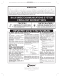
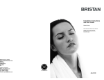
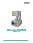
McDonald’s Beverage System Layout
Syrup Delivery (65 psi)
CO2 Delivery
A
CO2 Fill Box
Syrup Delivery Hose
F
Clean-In-Place
(CIP) Sanitize
System
B
D
H
E
C
Bulk Syrup
Vessel
(80 Gallon)
Bulk Syrup
Vessel
(80 Gallon)
(65 psi)
(65 psi)
Beverage Machine
(Carbonator)
Liquid CO2
Vessel
Mizer 450
or
Mizer 750
CO2
G
Emergency Back-Up CO2 Cylinder
Item
Description
Function
A
CO2 delivery truck fill line
Periodic transfer of liquid CO2 to on-site Mizer storage vessel
B
In-Store CO2 fill line
Transfer of CO2 from outside fill-box to Mizer storage vessel
C
CO2 gas-use line to beverage machine carbonator
CO2 gas supply at 90 -110 psi for beverage carbonation
D
CO2 gas-use line to bulk syrup and CIP
CO2 gas supply at 65 psi to push syrup to beverage machiine
E
CO2 gas-use line to fill box 2-pin connection
CO2 gas supply at 65 psi to pressurize bulk syrup delivery
F
Syrup delivery line
Bulk syrup delivery line routed through fill box conduit
G
Syrup supply tubing
Transfers syrup from bulk storage vessel to beverage machine
H
Water supply line
Suplies water to beverage machine and sanitation (CIP) system
44
Syrup Side Gas Use Regulator (65 psi)
Controls CO2 pressure to bulk syrup
45
Beverage Side Gas Use Regulator (90-125 psi)
Controls CO2 gas pressure to carbonator
6
Copyright: Chart Industries, Inc., May 2003
Carbo-Mizer 450 / 750 Vessel Specifications
Carbo-Mizer 450
Carbo-Mizer 750
Dimensions
Diameter
20 in (50.8 cm)
26 in (66 cm)
Height
71.8 in (182.0 cm)
73.5 in (187 cm)
Empty Weight
273 lb (124 kg)
430 lb (195 kg)
Full Weight
726 lb (329 kg)
1201 lb (545 kg)
Net Volume
48 gal (182 liters)
82 gal (310 liters)
CO2 Storage Capacity
(saturated @125 psig [8.6 bar g] )
453 lb (205 kg)
771 lb (350 kg)
Gas Use Connection
1/4” & 3/8” Hose Barb
1/4” & 3/8” Hose Barb
Fill Line Connection
5/8” Male 450 Flare
5/8” Male 450 Flare
Vent Line Connection
1/2” OD Tubing
1/2” OD Tubing
Rates and Pressures
CO2 Delivery Rate
Continuous*
Peak CO2 Delivery Rate For One Hour*
5.5 lb/hr (2.5 kg/hr)
(489 - 16oz drinks / hr)
10 lb/hr (4.5 kg/hr)
(889 - 16 oz drinks)
10 lb/hr (4.5 kg/hr)
(889 - 16oz drinks / hr)
18 lb/hr (8.2 kg/hr)
(1600 - 16 oz drinks)
Evaporation Rate**
2.5 lb/day (1.1 kg/day)
3.0 lb/day (1.4 kg/day)
Max. Allowable Working Pressure (MAWP)
300 psig (20.7 bar g)
300 psig (20.7 bar g)
ASME Relief Setting
300 psig (20.7 bar g)
300 psig (20.7 bar g)
Additional. Relief Setting
450 psig (31.0 bar g)
450 psig (31.0 bar g)
Design Criteria
Carbo-Mizer 450 & 750
(unless noted otherwise)
Design Specifications
ASME Section VIII, Division 1
Design Specifications
Meets with US and Canadian approvals
Fill System
Single Line, pressure differential
Patented Impurity Collection System
Mizer 450 only
Insulation Type
Vacuum with Super Insulation
Pressure Control
Pressure Building (PB) Circuit
Liquid Level Gauge
Float Type: Magnetic ‘Roto-Cal’
Outer Vessel Material
Stainless Steel
Inner Vessel Material
Stainless Steel
Floor mount Design (Meets NSF standards)
Six-Inch Permanent Legs
* Based on 11.25 lb of CO2 / 1000 16 oz. drinks
** No loss in normal applications
Copyright: Chart Industries, Inc., May 2003
7
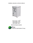
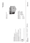
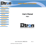
Vessel Parts Identification
McDONALD’S
Carbo-Mizer 450 P/N 11767303
Carbo-Mizer 750 P/N 11770676
16
68
52
53
69
48
75
76
15
47
54
44
73
22
33c
31
21
74
46
20
61
34
39
38
51
50
50
50
32
54
18
40
37
61
19
55
17
45
41
33d
43
34
30
50
49
36
50
57
42
35
61
33a
14
35
45
25
33b
47
67
46
94
48
69
70
71
72
8
Copyright: Chart Industries, Inc., May 2003
Vessel Parts Identification Continued
ITEM PART NO.
14
15
16
17
18
19
20
21
22
25
30
31
32
33a
33b
33c
33d
34
35
36
37
38
39
40
41
42
43
44
45
46
47
48
49
50
51
52
53
54
55
57
61
1210752
5411486
2910501
9094119
5411622
2952321
5411029
2300244
10591511
10643114
10591369
1212962
11082128
11708451
11708400
1716162
1716162
1716162
1716162
1211702
1210462
1210762
1311742
1717889
1717899
1210842
11767362
11767354
2015179
2111615
2111682
11673631
1310092
1013362
1716311
1013042
11044869
11741939
6910623
1611592
11741921
1110112
2710071
DESCRIPTION
QTY
FUNCTION
Cap, Brass Hex, (1/4 FPT)
Sight Gauge Protector, Clear
Screws, SS (1/4-20 x 5/8”) (not pictured)
Float Rod Assy. (42 1/2”) w/Magnet
Spring Retainer
Set Screw, Spring Retainer (not pictured)
Extension Spring
O-Ring, Liquid Level Gauge
Plug, Brass, Liquid Level Gauge
Liquid Level Gauge Assembly
Gauge, Liquid Level / Contents (Roto-Cal)
Brass Plug (1/8” MPT)
Ball Valve (3/8” FPT)
Relief Valve, 450 psig (1/2” MPT)
Relief Valve, 300 psig (1/2” MPT)
Ball Valve (1/4” MPT x 1/4” FPT)
Ball Valve (1/4” MPT x 1/4” FPT)
Ball Valve (1/4” MPT x 1/4” FPT)
Ball Valve (1/4” MPT x 1/4” FPT)
Street Tee (1/4” NPT)
Street Elbow, Brass 90D (1/4” NPT)
Cross, Brass, (1/4” FPT)
Nipple, Hex (1/4” NPT x 1/8” NPT)
Reset valve
Button, Brass
Adapter, Brass (1/4” FPT x 1/8” MPT)
Regulator, Shut-Off. 70 psi, 1/4” NPT
Regulator, Pressure Building (PB), 140 psi (1/4” NPT)
Pressure Gauge, 0-400 psi (1/4” MPT CBM)
Regulator, Syrup Side Gas Use, 65 psi (1/4” NPT)
Regulator, Final Line, 0-125 psi (1/4” NPT)
Pressure Gauge, 0-160 psi (1/8” MPT CBM)
Nipple, Hex, Brass, 1/4” NPT
Connector, Anchor, Brass 1/4” NPT
Check Valve, Gas Use
Elbow Connector, Brass, 90D (5/16” ODT x 1/4” MPT)
Branch Tee, (1/2” FPT)
Elbow (1/2” OD x 3/8” MPT)
Tube, Soft Copper Type L (1/2” OD, Nominal .375 in)
Adapter, Pipe-Away (3/8” FPT)
Run Tee, (1/2” ODT x 3/8” MPT)
Connector (5/8” ODT x 3/8” MPT 45o Flare)
Tubing, Stainless (5/16” OD)
1
1
3
1
1
1
1
1
1
1
1
1
1
1
1
1
1
1
1
2
2
1
1
1
1
1
1
1
1
1
1
2
2
2
1
8
1
1
ft
2
1
1
ft
Seals unused knuckle port
Protects sight gauge
Attach sight gauge to knuckle
Indicates liquid CO2 level in the vessel
Secures spring to float rod for adjustment
Secures Spring to float rod for adjustment
Provides tension on float rod
Seals brass plug to vessel
Secures the contents gauge to the vessel
Includes items 17, 18, 19, and 21
Indicates approximate liquid CO2 contents
Seals unused regulator port
Isolates CO2 fill hose from vessel.
Secondary inner vessel safety relief valve
Primary inner vessel safety relief valve
Isolates liquid-side of PB regulator
On / off control for carbonator gas supply
On / off control for syrup gas supply
On / off control for gas side of PB reg. and main gas
Connects gas supply circuit components
Connects isolation valves with gas supply
Connects gas supply and shut-down circuit
Connects reset valve to gas supply street tee
Restores pressure in gas use line
Push button for reset valve
Connects reset valve to shut-off circuit
Stops gas flow if line pressure drops to 70 psi
Controls vessel pressure building (PB) circuit
Displays internal vessel pressure
Controls CO2 pressure to bulk syrup
Controls CO2 gas pressure to carbonator
Indicates CO2 gas pressure to use point
Attaches regulator to fitting
Gas use line connection
Protects vessel components from back flow
Joins SS lines with plumbing components
Manifolds primary & secondary relief valves
Joins 450 psig relief valve to vent circuit
Joins vent circuit components
Joins 450 & 350 psig relief valves to vent fittings
Joins 450 & 350 psi relief valves to vent circuit
Connects CO2 fill hose to vessel
Gas use, pressure build, and shut-off plumbing line
Copyright: Chart Industries, Inc., May 2003
9
Vessel Parts Identification Continued
ITEM PART NO.
DESCRIPTION
QTY
FUNCTION
Includes connectors and tubing for CO2 installation
Prevents beverage system over-pressurization
(Included in installation kit P/N 9722439)
Prevents bulk syrup vessel over-pressurization
(Included in installation kit P/N 9722439)
Connects gas use line to vessel
(Included in installation kit P/N 9722439)
Connects carbonator gas-use line components
(Included in installation kit P/N 9722439)
Connects with carbonator gas-use line
(Included in installation kit P/N 9722439)
(Included in installation kit P/N 9722439)
Connection port for syrup delivery gas
(Included in installation kit P/N 9722439)
Connects with syrup gas-use line
(Included in installation kit P/N 9722439)
Protects flare fitting
(Included in installation kit P/N 9722439)
Syrup gas-use connections
(Included in installation kit P/N 9722439)
CO2 line connector to bulk syrup vessel
(Included in installation kit P/N 9722439)
Syrup gas-use line
(Included in installation kit P/N 9722439)
(Included in installation kit P/N 9722439)
Carbonator gas line
(Included in installation kit P/N 9722439)
(Included in installation kit P/N 9722439)
Covers vacuum pump-out port
Denotes McDonald’s approved equipment
Describes vessel safety and operations
Denotes CO2 vessel (UN 2187)
Operation, caution, approval, and manufacturer
Operation, caution, approval, and manufacturer
Included in label kits
Included in label kit 11197611
Included in label kit 11197646
-
9722439
Installation Kit, McDonald’s CO2
-
67
1812352
Relief Valve, 130 psi (1/4”)
1
68
1812342
Relief Valve, 75 psi (1/4”)
1
69
1213092
Tee, Brass (1/4” F x 1/4” F x 1/4” MPT)
2
70
1111502
Union, brass (1/4” MPT x 1/4” Flare)
1
71
1611821
Elbow, SS (1/4” FL x 3/8” Hose)
1
72
3411331
Clamp, Stepless Ear For 3/8” ID Tubing
5
73
1111512
Tee, Run, Brass (1/4” MPT)
1
74
1611461
Elbow, SS (1/4” Hose x 1/4 ODT)
1
75
1111292
Cap Nut (1/4” ODT 45D Flare)
1
76
3411511
Clamp, Stepless Ear For 1/4” ID Tubing
6
-
6511706
Quick Connect, Two Slot (1/4” Tube) (not pictured)
1
-
2811606
Tubing, 1/4” ID Red Line, 20 ft. (not pictured)
1
-
3411312
Clamp, Stepless Ear For 1/4” ID (not pictured)
4
-
2811586
Tubing, 3/8” ID Red Line, 100 ft. (not pictured)
1
94
-
2811616
3911217
11541259
3836609
10807553
11197611
11197646
11784496
3832679
10915896
Tubing, 1/4” ID Green Line, 5 ft. (not pictured)
Cap, Black
Label, McDonald’s
Label, Operations
Label, CO2 Vessel
Label Kit, NYCFD Approval, (Stationary Installation)
Label Kit, NYCFD Approval, (Portable Installation)
Label Only, Caution Carbon Dioxide
Decal Only, CO2 NYCFD COA #4912 (Stationary)
Decal Only, CO2 NYCFD COA #4748 (Portable)
1
1
1
1
1
1
1
1
1
1
10
Copyright: Chart Industries, Inc., May 2003
Fill Box Parts & Hose Identification
Surface Mount Fill Box (P/N 9722329)
1
Flush Mount Fill Box Shell (Without Panel) (P/N 8512629)
Flush Mount Fill Panel (With Fttings) (P/N 9722859)
7
12
5
10
13
6
77
64
11
10
65
76
13
64
3
2
65
12
9
76
77
7
ITEM PART NO.
80
4
9
6
1
DESCRIPTION
QTY.
CO2 Fill Fitting, Brass (includes retainer ring)
Lock Assembly (includes key) for Flush Mount Box
Key for Lock Assembly (not pictured)
Lock and Key Assembly for Surface Mount Box
Surface-Mount CO2 Fill Box (without fittings)
Flush-Mount Fill Box Panel (without fittings)
Quick Connect, 2-Pin
O-Ring
Outside O-Ring ( 5/16” x 1/2”)
Machine Screw, SS (#10-32 x 1/2”)
Locknut, SS (10 x 32) with nylon insert
Screws, SS (#8 x 1/2”)
CO2 Fill and Vent Hose Kit (15 ft. each line)
CO2 Fill Hose Only, 15 ft. (2000 psi & FDA)
Vent Hose Only, 15 ft
Tubing, red line (1/4” ID)
Tubing, green line (1/4” ID)
Clamp, Stepless (for 1/4” ID green line tube)
Clamp, Stepless (for 1/4” ID red line tube)
Conduit, Syrup Pass-Thru
1
1
1
1
1
1
1
2
3
4
5
6
7
9
10
11
12
13
64
65
76
77
80
11014459
4310689
4310959
4311129
8505789
8517839
6511631
12881917
4710619
2913591
2915131
2913981
10973324
10802947
2811726
2811606
2811616
3411511
3411321
8503796
81
10772160 Pipe Cap 2-1/2” PVC
Copyright: Chart Industries, Inc., May 2003
1
6
6
6
1
1
1
20 ft
5 ft
6
4
1
1
11
81
FUNCTION
Connection for CO2 delivery vessel hose
Locks fill box door
Replacement key for fill box
Locks fill box door
Allows outdoor filling and venting of vessel
Holds brass fill fitting and 2-pin connector
CO2 connection for syrup delivery
Seals 2-pin connection for syrup delivery gas
Secures fill fitting retainer to fill box
Secures fill fitting retainer to fill box
Secures fill panel to fill box
(Included in installation kit P/N 9722439)
Transfers liquid CO2 from fill box into vessel
Vents excess vessel pressure outdoors
(Included in installation kit P/N 9722439)
(Included in installation kit P/N 9722439)
(Included in installation kit P/N 9722439)
(Included in installation kit P/N 9722439)
(Included in installation kit P/N 9722439)
Syrup pass-thru cover
(Included with fill-box shell P/N 8512629)
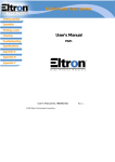
Portable Installation Components
Syrup Gas Use
Vent Line
(See page 8)
119
55
118
Carbonator Gas Use
117
123
116
122
121
Fill Fitting
118
69
104
120
116
67
69
101
68
ITEM PART NO.
30
DESCRIPTION
QTY
103
102
FUNCTION
30
11082128
Ball Valve (3/8” FPT) (equipped on vessel)
1
67
1812352
Relief Valve, 130 psi (1/4”)
1
68
1812342
Relief Valve, 75 psi (1/4”)
1
Protects bulk syrup vessels from over-pressurization
69
1213092
Branch Tee, Brass (1/4”F x 1/4”F x 1/4” MPT)
2
Joins quick-connect and relief valve to gas-use port
101
10662041
1
102
1212062
CO2 Fill Fitting, Brass (3/4” thresd)
Hex Bushing (3/8” FPT x 3/4” MPT)
1
Connects CO2 transfer hose to vessel CO2 fill line
103
1310072
Hex Nipple, (3/8” NPT x 1-1/4” long)
1
Joins fill fitting to vessel
104
10933218
1
116
9722509
CO2 Fill Fitting Support Bracket
Tank Boss Adapter (1/4” MPT)
2
Secures CO2 fill fitting to vessel
117
6511631
Quick Cinnect, Two-Pin Lock
1
Connects and releases syrup gas-use line
118
4710619
O-Ring (1/2” OD)
2
Seals pin connector when joined
119
6511706
Quick Connect, Two-Slot
1
Connects and releases syrup gas-use line
120
1611861
Quick Connect, Three-Pin Lock
1
Connects and releases carbonator gas-use line
121
10806690
Quick Connect, Three-Slot
1
Connects and releases carbonator gas-use line
122
10727959
Adapter Flare to Barb (1/4” F)
1
Barb connector for carbonator gas-use line
123
10806711
Washer, 1/4” Flare
1
Seals connection of barb and three-slot connectors
12
Isolates CO2 fill hose from vessel.
Protects the beverage system from over-pressurization
Joins fill fitting to vessel
Connects pin connector to vessel gas line
Copyright: Chart Industries, Inc., May 2003
Troubleshooting Guide
CO2 Storage Vessel
INDICATION
No CO2 to carbonator or
syrup systems.
OR
Carbonated drinks are flat.
POSSIBLE CAUSE
CORRECTIVE ACTION
1. Switch to emergency CO2 gas cylinder.
CO2 storage vessel is empty.
2. Call CO2 supplier for delivery.
Isolation valves (33a, b, c, d) closed.
Vessel pressure (43) is low
(110 psi or less).
Open valve or valves as needed.
1. Switch to emergency CO2 gas cylinder.
2. Stop CO2 withdrawal from bulk CO2 vessel by
closing isolation valves 33b and 33c.
3. If vessel pressure fails to rebuild see section on
low vessel pressure.
Pressure building regulator (42) not
operating properly
1. Ensure that isolation valves (33a & 33d) are open.
2. Valve handles should be parallel with the line.
3. Regulator is set too low, plugged, or faulty.
Call CO2 service agent.
Frost on the bottom or
sides of the vessel.
Unknown
Call CO2 service agent.
A normal condition during or
following CO2 use.
None
Leak in beverage system and/or gas
supply lines or CO2 fill box.
(When frost is present after extended
periods of no CO2 use.)
Frost on the top of
the vessel.
Normal condition during periods of
CO2 use.
CO2 leak from the beverage or syrup
system (rupture disc), plumbing, or
CO2 fill box.
(Frost present after extended periods
with no intentional CO2 use.)
1. See “Safety”. Evacuate & ventilate. Check for
frost in the morning before CO2 has been used.
If possible, locate and correct leak.
2. Call appropriate equipment service agent.
None
1. See “Safety”. Evacuate & ventilate the room.
2. Check for frost in the morning before CO2 use.
Other indicators include high CO2 usage, frost on
sides of the vessel, low vessel pressure, etc.
Locate & correct leak if possible.
3. Call appropriate service agent.
Constant low
vessel pressure.
(gauge 43 below 110 psi)
PB regulator (42) set low or plugged.
Call CO2 service agent for service.
PB shut-off valves (33a & 33d) closed.
Open valve by turning handle parallel to line.
CO2 leak from vessel plumbing, CO2
fill box and/or vessel safety system
Copyright: Chart Industries, Inc., May 2003
13
1. See “Safety”. Evacuate & ventilate the room.
2. Call CO2 service agent.
Troubleshooting Guide Continued
CO2 Storage Vessel
INDICATION
Constant high vessel
pressure.
(43 over 200 psi)
High CO2 consumption.
POSSIBLE CAUSE
CORRECTIVE ACTION
Normal condition for a few days
following a CO2 delivery.
None
Normal when little or no CO2 is used.
None
PB regulator (42) set too high.
Call CO2 service agent.
Vessel has a weak vacuum.
Call CO2 service agent.
Increased beverage sales or CO2 use.
None
Vessel pressure (43) constantly high.
See section on vessel pressure too high.
CO2 leak from vessel plumbing, CO2 fill
box, gas lines, and/or beverage or syrup
use-point equipment.
CO2 vessel will not fill.
1. See “Safety”. Evacuate & ventilate room.
2. Locate & correct leak if possible
3. Call appropriate service agent.
Error in CO2 supplier invoice.
Check CO2 usage history / pattern against
supplier invoices. Consult CO2 supplier.
CO2 vessel is already full.
None
Fill valve (30) is shut off or is faulty.
Consult CO2 service agent.
Brass fill fitting in CO2 fill box and/or on
truck’s delivery hose is faulty.
Differential between store vessel pressure
and delivery pressure is too small.
1. Consult with CO2 supplier or service agent.
2. Have brass fill fitting(s) replaced if needed.
1. Verify delivery vessel pressure is at least 50 psi
higher than the store vessel pressure (43).
2. Vent store vessel to lower pressure if needed.
3. Never vent store vessel pressure to lower than 125 psi.
Delivery vessel is empty.
Consult supplier. Arrange for another delivery.
Delivery vessel empty or truck delivery
hose is obstructed, e.g. vehicle stopped
on hose or hose is bent.
Ask driver to make another delivery or clear
obstruction or wait until obstruction clears.
14
Copyright: Chart Industries, Inc., May 2003
Troubleshooting Guide Continued
CO2 Storage Vessel
INDICATION
Hissing sounds or
evidence of gas leak.
POSSIBLE CAUSE
CORRECTIVE ACTION
Normal for short periods of time from
some regulators and relief valves.
Large leaks from elsewhere in the system,
sustained leaks, or frequent leaks are not
normal.
Observe leak, if it is not large and does not last
long and occur frequently, no action is needed.
1. See “Safety”.
2. Evacuate all personnel from affected areas.
3. Ventilate the area.
4. Call CO2 service agent.
Final line / gas use
pressure gauges
(46) indicate less
than 65 psi on the
syrup side and/or
less than 100 psi on
the carbonator side.
Final line regulators (44) or (45)
intentionally set lower by beverage
service agent.
None
Final line regulators (44) or (45) not
operating in proper pressure range.
Call CO2 service agent.
Final line pressure gauge (46) damaged
or faulty.
Call CO2 service agent.
One or more of the causes listed in “no
CO2” or “flat drinks” problem section.
1. See indication sections regarding “no CO2”,
“flat drinks” etc.
2. Call CO2 service agent.
Copyright: Chart Industries, Inc., May 2003
15
Troubleshooting Guide Continued
Fill Box
INDICATION
Fill box door will
not close, lock, or
open.
POSSIBLE CAUSE
CORRECTIVE ACTION
Wrong key.
1. Verify correct key and retry.
2. Contact CO2 supplier for spare key.
3. Order new key.
Lock dirty or damaged.
1. Clean and oil lock
2. Replace lock if necessary
Brass fill fitting in
fill box leaking
or hissing.
Particle of ice or debris caught in fill
fitting poppet.
1. If driver is still on site, reconnect CO2 delivery hose
and then disconnect.
2. If driver is not available, carefully press poppet with
dull instrument to re seat poppet.
3. If leak continues after line warms, close the fill
isolation valve (30) and call service agent.
Threads on brass
fill fitting are
worn or stripped.
CO2 is venting
from fill box.
Fitting is defective or sealing surface is
worn due to normal wear.
Close the fill isolation valve (30) on the vessel and
call service agent to replace fitting.
Normal wear. Fill fitting must be
replaced.
Contact CO2 service agent to replace fitting.
Fill fitting cross threaded with the CO2
delivery hose coupler
Contact CO2 service agent to replace fitting.
Normal during CO2 delivery.
None
Normal for short periods of time if vessel
pressure is at or over 300 psi
Fill fitting is not sealing properly.
1. NONE if for short period(s) of time
2. If vessel pressure consistently over 300 psi,
see section on vessel pressure too high.
Call CO2 service agent to replace fitting.
16
Copyright: Chart Industries, Inc., May 2003
Service and Parts
Service and Maintenance
thorough preventative maintenance check on
the system at least once every two years.
The check should be done to ensure safety and
optimal system performance.
1. Service or maintenance work on the
Carbo-Mizer CO2 storage system should
be performed only by Chart trained and
authorized professional service agents who are
familiar with CO2, bulk liquid CO2 pressure
vessels, and all pertinent safety and service
procedures. Chart recommends the use of
Chart approved replacement parts. Contact
Chart for the name of the authorized service
agent(s) in your area.
4. The Carbo- Mizer bulk CO2 storage system
has no user serviceable parts. An authorized
professional service agent should perform all
service work.
NOTE: Any attempt by an unauthorized
person to service or perform unauthorized
modifications on the equipment will void
the warranty.
2. Before calling for service or troubleshooting
assistance, please have the following
information at hand:
• Serial number of the vessel
• Description of the problem
• Readings from:
- the contents gauge (22),
- the vessel pressure gauge (43),
- the final line pressure gauges (46).
• Any special observations
(for example: unusual frosting or events
related to the problem)
Ordering Parts Or Service
For service contact your local authorized MVE
Beverage Systems CO2 supplier or equipment
service agent. For parts contact your local
authorized Chart service agent or order on-line
directly from Chart at www.chartparts.com.
Know the model and serial number of the vessel
for which you are ordering parts. To assure that
your order is processed promptly, list each item
separately, being careful to specify the quantity,
the part number, and the description of each
item being ordered.
3. Chart recommends that a qualified
professional service agent perform a
Important Telephone Numbers
Company
Contact Person
Phone Number
CO2 Supplier
__________________________
_____________________
After-Hours / Emergency Number
_____________________
CO2 Service Agent
__________________________
_____________________
CO2 Equipment Installer
__________________________
_____________________
MVE Beverage Systems Customer Service
(952) 882-5000 or (800) 247-4446 {toll free in US}
MVE Beverage Systems Technical Service
(952) 882-5000 or (800) 253-1769 {toll free in US}
Copyright: Chart Industries, Inc., May 2003
17
Warranty
WARRANTY POLICY
WARRANTY CLAIMS PROCEDURE
Chart Industries, Inc. warrants to McDonald’s
Restaurants (the purchaser) the McDonald’s Mizer
bulk CO2 system equipment for one (1) year from the
Chart invoice date, that said equipment shall be free
from any defects in workership and materials. Chart
also warrants the reliability of the vacuum in the CO2
storage vessel for 5 (five) years from the date of the
original Chart invoice.
1. All warranty claims must be previously authorized
by: Chart Ind., Inc. Telephonic / electronic approval
may be obtained by contacting Chart’s MVE Beverage
Systems Technical / Customer Services at:
• Telephone: 952-882-5000
800-253-1769
(Toll free in U.S.)
• Facsimile: 952-882-5185
Purchaser agrees that as a pre-condition to any Chart
liability hereunder, Purchaser or its appointed agents
shall fully inspect all goods immediately upon delivery
and shall give Chart written notice of any claim or
purported defect within ten (10) days after discovery
of such defect.
or by writing to:
Chart Industries, Inc.
MVE Beverage System Technical Service
3505 County Road 42 West
Burnsville, MN 55306-3803
USA
As a further pre-condition to any Chart liability
hereunder, an approved Chart service company must
supply both parts replacement and labor. Chart may
elect to repair or replace such equipment or any
defective component or part thereof which proves
to be defective, or to refund the purchase price paid
by the original Purchaser. Chart shall not be liable
for defects caused by the effects of normal wear and
tear, erosion, corrosion, fire, explosion, misuse, or
unauthorized modification.
2. Authorization must be obtained from Chart prior
to shipping any equipment to Chart facilities. In order
to process the return of a vessel its model and serial
number must be provided. If approved, a Return
Material Authorization (RMA) number will be
provided. The RMA number must be prominently
indicated on the packing slip and any packaging that
accompanies the goods being returned. The customer
returning the goods is responsible for all freight,
proper packing, and any damage incurred during
shipment of the goods back to Chart.
Alterations or repair by others than those designated
and approved by Chart or operation of such equipment
in a manner inconsistent with Chart accepted practices
and all operating instructions, unless pre-authorized in
writing by Chart, shall void this Warranty.
Chart’s sole and exclusive liability under this Warranty
is to the Purchaser and shall not exceed the lesser of
the cost of repair, cost of replacement, or refund of the
net purchase price paid by the original Purchaser.
Chart is not liable for any losses (including CO2),
damages, or costs of delays, including incidental or
consequential damages. Chart specifically makes
no warranties or guarantees, expressed or implied,
including the warranties of merchantability or fitness
for a particular purpose or use, other than those
warranties expressed herein.
18
Copyright: Chart Industries, Inc., May 2003
System Flow Schematic
Pressure-Builder Isolation Valve (Gas Side) (33d)
Pressure-Builder Regulator (42)
Contents Gauge (22)
Push-Button Reset Valve (38)
Syrup Gas Isolation Valve (33c)
Syrup Gas Pressure Gauge (46 )
Syrup Gas Regulator (44)
Secondary Relief Valve (31)
Syrup Gas
Relief Valve (68)
Primary Relief Valve (32)
Carbonator Gas
Pressure Gauge (46)
Pressure-Builder Isolation Valve
(Liquid Side) (33a)
Carbonator Gas
Relief Valve (67)
Liquid Fill Isolation Valve (30)
Carbonator Gas Regulator (45)
Gas-Use Isolation Valve (33b)
Gas-Use Check Valve (49)
Shutdown Regulator (41)
Vessel Pressure Gauge (43)
Pressure Building Coil
Collection Ring
(Mizer 450 only)
Collection Ring Drain Valve
McDonald’s Mizer 450 & 750 CO2 System
Copyright: Chart Industries, Inc., May 2003
19
+
• Order parts directly from Chart through a
personalized account at www.chartparts.com.
• Simply establish an account password and “log-in.”
• Service is available 24 hours a day and
provides same-day shipping on all stock parts.
• Chartparts provides access to shipment tracking,
transaction history, and personalized account
information for convenient account management.
Chart Industries, Inc.
Copyright © 2003 Chart Industries
3505 County Road 42 West
Burnsville, MN 55306-3803
PART NUMBER 11817059 5/03
chartbeverage.com
U.S. 800-247-4446 • Worldwide 952-882-5000 • Fax 952-882-5185 • www.chart-ind.com • e-mail: [email protected]
Copyright: Chart Industries, Inc., May 2003