1
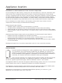
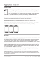
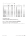
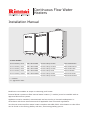
Continuous Flow Water
Heaters
Installation Manual
To suit models:
Rinnai Infinity VT16
REU-VR1620WG
Rinnai Infinity HD200
REU-VRM2632WC
Rinnai Infinity VT20
REU-VR2024WG
Rinnai Infinity HDi200
REU-VR2632FFUG
Rinnai Infinity VT24
REU-VR2426WG
Rinnai Infinity HD250
REU-VR3237WG
Rinnai Infinity VT26
REU-VR2626WG
Rinnai Infinity EF24
REU-K2430WG
Rinnai Infinity VTa26
REU-VR2626WGT
Rinnai Infinity EF250
REU-KM3237WD
Rinnai Infinity EFi250
REU-KM3237FFUD
i = internal
a = aggressive water
Models are not suitable as a spa or swimming pool heater.
Internal Rinnai continuous flow internal water heaters (‘i’ models) must be installed with an
approved Rinnai flue system.
Appliance must be installed, commissioned and serviced by a licensed tradesperson in
accordance with these instructions and all applicable local rules and regulations.
Your Rinnai continuous flow water heater complies with NZS 5262. A declaration to this effect
can be found on the Energy Safety web site; www.energysafety.govt.nz.
Contents
Before installation
3
Applicable models
3
Appliance location
4
General installation information
6
Connections and fittings
8
Dimensions - VT and HD range
9
Dimensions - EF range
10
EF250 models: Earthing the unit
11
Condensate Drain - EF models only
12
Controllers - general
14
Controllers - Universal installation
16
Controllers - Kitchen Deluxe installation
17
Controllers - Bathroom Deluxe installation
18
Controllers - communication cables
19
Commissioning
21
Recommended solar system layout
22
Dip switch settings
23
WARNING
Improper installation, adjustment, alteration, service or maintenance
can cause property damage, personal injury or loss of life.
For assistance or additional information contact Rinnai on
0800 TO RINNAI (0800 86 746 624).
Before installation
Unpack appliance and flue components (if applicable) and check for damage.
DO NOT install any damaged items.
Check all components have been supplied and that you have the correct gas type.
Read these instructions to get an overview of the steps required before starting the
installation. Failure to follow these instructions could cause a malfunction of the
appliance. This could result in serious injury and property damage.
For Rinnai continuous flow water heaters used in solar installations, refer
‘Recommended Solar System Layout’.
32 kg
Heavy
The Rinnai Infinity EF models are 32 kg. Please use care when lifting and seek
assistance if required.
This appliance must be installed in accordance with:
• Current AS/NZS3000, AS/NZS3500, NZS 5261 and G12/AS1
• Rinnai installation instructions
• Local regulations and municipal building codes
Installation, service and removal must be by an authorised person only.
Applicable models
These installation instructions apply to the following Rinnai continuous flow water heaters.
Rinnai Infinity VT16
External
REU-VR1620WG
Rinnai Infinity VT20
External
REU-VR2024WG
Rinnai Infinity VT24
External
REU-VR2426WG
Rinnai Infinity VT26
External
REU-VR2626WG
Rinnai Infinity VTa26
External
REU-VR2626WGT
Rinnai Infinity HD200
External
REU-VRM2632WC
Rinnai Infinity HDi200
Internal
REU-VR2632FFUG
Rinnai Infinity HD250
External
REU-VR3237WG
Rinnai Infinity EF24
External
REU-K2430WG
Rinnai Infinity EF250
External
REU-KM3237WD
Rinnai Infinity EFi250
Internal
REU-KM3237FFUD
i
a
= internal
= aggressive water unit
Rinnai New Zealand Ltd.
3
Continuous Flow Water Heater Installation Manual:
03-11
Appliance location
Installation in environments free from corrosive compounds
Air surrounding the water heater, venting and vent termination(s) is used for combustion and
must be free from compounds that cause corrosion of internal components. These include
corrosive compounds that are found in aerosol sprays, detergents, bleaches, cleaning solvents,
oil based paints/varnishes, and refrigerants. Therefore Rinnai recommends outdoor models
be used for these locations where possible. The water heater, venting and vent termination(s)
should not be installed in any areas where the air may contain these corrosive compounds.
If it is necessary for a water heater to be located in areas which may contain corrosive
compounds, Rinnai strongly recommends the following:
Indoor/internal water heaters:
•
•
•
•
DO NOT install in areas where contaminated air is present
Consider before installation where air has the ability to travel within the building
Chemicals that are corrosive in nature should not be stored or used near the water heater
Where possible, install the water heater in a sealed closet so that it is free of contaminated
indoor air
Outdoor/external water heaters and vent terminations of indoor/internal water heaters:
• Install as far away as possible from exhaust vent hoods
• Install as far away as possible from air inlet vents—corrosive fumes may be released
through these vents when air is not being brought in through them
• Chemicals that are corrosive in nature should not be stored or used near the water heater
or vent termination
Damage and repair due to corrosive compounds in the air is not covered by warranty.
Internal models
Internal models are designed for indoor installations only. They may be installed
in an enclosure if the requirements of NZS 5261 are satisfied. An enclosure is
defined as a compartment, enclosed area or partitioned off space primarily used
for the installation of the appliance. If installed in an enclosure either internally or
externally, the location should be ventilated to allow gas to dissipate.
They must be mounted on a vertical structure with the water and gas connections
on the underside pointing downwards. For appliances installed in roof spaces or elevated
structures, specific requirements apply. Refer to NZS 5261 section 1.6 for details.
This appliance MUST be used with an approved Rinnai flueing system. The use of a non-Rinnai
flueing system may result in a dangerous situation and violates regulations.
This appliance must be located so that the flue terminal exits the building at a suitable point,
refer ‘Minimum Clearances Required for Flue Terminals’, NZS 5261:2003.
Manufacturer’s instructions for model REU-KM3237FFUD (EFi250); for reference j, gas
appliances over 200 MJ/h input, use ≥ 300 mm.
Rinnai New Zealand Ltd.
4
Continuous Flow Water Heater Installation Manual:
03-11
Appliance location
External models
External models are designed for outdoor installations only. They must be located
in an above ground open-air situation with natural ventilation, without stagnant
areas, and where gas leakage and products of combustion are rapidly dispersed
by wind and natural convection.
They must be mounted on a vertical structure with the water and gas connections
on the underside pointing downwards. For appliances installed on elevated
structures or under floors specific requirements apply. Refer to NZS 5261 for
details.
This appliance must be located so that the flue terminal exits the building at a suitable point,
refer ‘Minimum Clearances Required for Flue Terminals’, NZS 5261:2003.
Manufacturer’s instructions for model REU-KM3237WD (EF250); for reference j, gas
appliances over 200 MJ/h input, use ≥ 300 mm.
When multiple units of the same model are installed on the same vertical face, with the flue
terminals at the same height, they can be installed next to each other (as shown).
All models
This appliance must be placed as close as possible to the most frequently used hot water outlet
or outlets to minimise the delay for hot water delivery.
For installations where the distance between the water heater and the outlets is considerable,
a flow and return system can be used to minimise the waiting time for hot water delivery.
Alternatively, multiple appliances can be strategically placed to serve different outlets. Contact
Rinnai for further information.
An AC 230 V, 10 Amp, earthed power point must be provided adjacent to the appliance. For
outdoor installations, this power point must be weatherproof. It must be clear of the gas and
water connections to the appliance and also the flue exhaust and water pressure relief valve.
The power cord of the appliance is 1.5 m long.
All appliances must be installed to ensure access can be gained without hazard or undue
difficulty for inspection, repair, renewal or operational purposes. Sufficient clearances shall
allow access to and removal of all serviceable components.
Appliances should not be mounted higher than 3.5 m above the ground or floor level unless
the customer can arrange permanent and safe access or can provide another means of access
such as scissor or boom lifts.
Rinnai New Zealand Ltd.
5
Continuous Flow Water Heater Installation Manual:
03-11
General installation information
Catch pan
It is important a suitably drained catch pan is fitted (especially for internal units) where
damage could be caused by discharge from the water heater. Provision must be made for safe
disposal of any leaking water to an external location.
Flued water heaters (internal units)
The chart below highlights the maximum flue length and number of bends. It also shows the
difference between a short and long flue—this is important if changing settings (dip switches).
Number of 90 Degree Bends
0
1
2
3
4
1
2
Flue Length (m)
3
Short flue
setting
4
5
6
7
Long flue
setting
9
11
13
15
Maximum flue length
Mounting the appliance
Refer ‘Connections and Fittings’ for individual appliance weights. The wall or structure on which
these units are to be mounted must be capable of supporting these weights and the associated
pipe work.
Ensure suitable fixing screws or bolts are used to secure the units to the walls, in accordance
with NZS 5261 (section 5.0). Wooden plugs shall not be used.
The top bracket has a keyhole slot (circled below) so the appliance can be positioned by
hanging it on one screw while the other screws are secured.
Rinnai New Zealand Ltd.
6
Continuous Flow Water Heater Installation Manual:
03-11
General installation information
Pipe sizing
Refer ‘Connections and Fittings’ for appliance gas consumption. If the gas pipe sizing is
insufficient the customer will not get the full performance benefit. Gas pipe sizing must
consider the gas input to this appliance as well as all the other gas appliances in the
premises. The gas meter and regulator must be specified for this gas rate. An approved
sizing chart such as the one in NZS 5261 should be used.
Water pipe sizing and layout should be performed in accordance with AS/NZS3500. All hot
water pipe work should be insulated to optimise performance and energy efficiency.
Water delivery temperature
Local regulations and/or requirements of AS/NZS3500.4 must be considered regarding
the temperature limitations of hot water supplied to areas used primarily for personal
hygiene. The temperature of these areas may be limited to 55 °C or less.
If the appliance is to deliver water primarily for the purposes of personal hygiene in an
early childhood centre, school, nursing home or similar facility as defined in AS/NZ3500.4 a
Temperature Limiting Device (TLD), such as a Tempering Valve may be required (even if the
appliance is set to 55 °C or less). For these types of applications contact Rinnai.
Requirements for Rinnai Continuous Flow Units Installed Without Controllers
55 °C
> 55 °C
Diagram 1 - 55 °C Appliance
> 55 °C
< 55 °C
< 55 °C
Diagram 2 - Not a 55 °C Appliance
(TLD = Temperature Limiting Device)
When the continuous flow unit is set to deliver water at a temperature higher than 55 °C, it will
be necessary to fit a Temperature Limiting Device for delivery to areas used for the purposes of
personal hygiene. Refer Department of Building and Housing G12.
Water supply
Refer ‘Connections and Fittings’ for applicable water pressures. Approved pressure
limiting valves may be required if the stated maximum rated water supply pressures
are exceeded. To achieve the rated flow, the stated minimum water supply
pressures must be supplied. The water heaters will operate at lower pressures but
will not achieve the rated flow.
Water chemistry and impurity limits are stated in our detailed warranty statement. Most
metropolitan water supplies fall within these requirements. If you are unsure about the quality
of the water, please contact Rinnai and we will provide you with the details of an authorised
agency who are able to test your water for compliance to Rinnai standards. If sludge or foreign
matter is present in the water supply, a suitable filter or strainer should be incorporated in the
water supply to the water heater.
Rinnai New Zealand Ltd.
7
Continuous Flow Water Heater Installation Manual:
03-11
Connections and fittings
Models
Gas Consumption
MJ/h
Water
Supply kPa
Min.
Weight
kg
Max.
Fittings
Condensate
Hot
Cold
Gas
15
R½
(15 mm)
R½
(15 mm)
R¾
(20 mm)
1000
16
R¾
(20 mm)
R¾
(20 mm)
R¾
(20 mm)
180
1000
17
R¾
(20 mm)
R¾
(20 mm)
R¾
(20 mm)
199
180
1000
17
R¾
(20 mm)
R¾
(20 mm)
R¾
(20 mm)
VTa26
REU-VR2626WGT
199
180
1000
17
R¾
(20 mm)
R¾
(20 mm)
R¾
(20 mm)
HD200 Ext
REU-VRM2632WC
199
140
1000
21
R¾
(20 mm)
R¾
(20 mm)
R¾
(20 mm)
HDi200 Int
REU-VR2632FFUG
195
140
1000
21
R¾
(20 mm)
R¾
(20 mm)
R¾
(20 mm)
HD250 Ext
REU-VR3237WG
250
200
1000
29
R¾
(20 mm)
R¾
(20 mm)
R¾
(20 mm)
EF24 Ext
REU-K2430WG
162
240
1000
27
R¾
(20 mm)
R¾
(20 mm)
R¾
(20 mm)
R½
(15 mm)
EF250 Ext
REU-KM3237WD
211
240
1000
32
R¾
(20 mm)
R¾
(20 mm)
R¾
(20 mm)
R½
(15 mm)
EFi250 Int
REU-KM3237FFUD
211
240
1000
32
R¾
(20 mm)
R¾
(20 mm)
R¾
(20 mm)
R½
(15 mm)
VT16 Ext
REU-VR1620WG
125
120
1000
VT20 Ext
REU-VR2024WG
160
160
VT24 Ext
REU-VR2426WG
188
VT26 Ext
REU-VR2626WG
Service connection points
These dimensions are NOT an indication of the pipe sizes required.
An approved full flow isolation valve and disconnection union MUST be fitted to the cold water
inlet. A non-return valve is not required unless required by local regulations.
Isolation valves must be fitted so the appliance can be removed.
Purge gas and cold water supply lines to remove air and swarf before final connection of the
appliance. Swarf in the gas or water supplies may cause damage.
Rinnai New Zealand Ltd.
8
Continuous Flow Water Heater Installation Manual:
03-11
Dimensions - VT and HD range
A
B
I
G
J
H
C
F
D
L
K
E
M
A
Width
350
350
350
350
350
(REU-VR3237WG)
(REU-VR2632FFUG)
HD250 Ext
HDi200 Int
(REU-VRM2632WC)
HD200 Ext
(REU-VR2626WGT)
VTa26 Ext
(REU-VR2626WG)
VT26 Ext
(REU-VR2426WG)
VT24 Ext
(REU-VR2020WG)
VT20 Ext
VT16 Ext
(REU-VR1620WG)
Dimension (mm)
350
350
470
B
Depth
194
194
194
194
194
250
235~275
244
C
Height - Unit
530
530
530
530
530
600
600
600
D
Height - Including Brackets
571
571
571
571
571
636
641
644
E
Hot Water Outlet (from wall)
87
87
87
87
87
95
91~131
115
F
Hot Water Outlet (from centre)
105
105
105
105
105
110
110
61
G
Cold Water Inlet (from wall)
68
68
68
68
68
74
70~110
99
H
Cold Water Inlet (from centre)
10
10
10
10
10
27*
27*
52
I
Gas Connection (from wall)
77
77
77
77
77
103
99~139
61
J
Gas Connection (from centre)
83
83
83
83
83
89
89
110
K
Condensate Outlet (from wall)
•
•
•
•
•
•
•
•
L
Condensate Outlet (from centre)
•
•
•
•
•
•
•
•
M
Gas: Length Gas Connection (from base)
40
40
40
40
40
41
41
41
Cold: Length of Cold Water Inlet (from base)
50
50
50
50
50
51
51
51
Hot: Length of Hot Water Outlet (from base)
39
39
39
39
39
42
42
42
* this measurement is to the left of the centre line
HDi200, height of flue spigot from base of unit ≈ 85 mm
Rinnai New Zealand Ltd.
9
Continuous Flow Water Heater Installation Manual:
03-11
Dimensions - EF range
A
B
I
G
H
C
J
F
D
L
K
E
M
Dimension (mm)
EF24 Ext
(REU-K2430WG)
EF250 Ext
(REU-KM3237WD
EFi250 Int
(REU-KM3237FFUD)
A
Width
350
470
470
B
Depth
277
283.1
257~307
C
Height - Unit
600
654
654
D
Height - Including Brackets
644
721.6
721.6
E
Hot Water Outlet (from wall)
164.5
100
100~150
F
Hot Water Outlet (from centre)
100
100
100
G
Cold Water Inlet (from wall)
83
64.6
64.6~114.6
H
Cold Water Inlet (from centre)
53*
27.2
27.7
I
Gas Connection (from wall)
70.5
89
89~139
J
Gas Connection (from centre)
25
103.2
103.2
K
Condensate Outlet (from wall)
33
122.6
122.6
L
Condensate Outlet (from centre)
M
Gas: Length Gas Connection (from base)
132
195
195
51
40.2
40.2
Cold: Length of Cold Water Inlet (from base)
62
50.2
50.2
Hot: Length of Hot Water Outlet (from base)
41
41.2
41.2
Condensate Connection Length (from base)
24
22.4
22.4
* this measurement is to the left of the centre line
Rinnai New Zealand Ltd.
10
Continuous Flow Water Heater Installation Manual:
03-11
EF250 models: Earthing the unit
Removing the cover and earthing the unit
For the Rinnai condensing continuous flow water heaters (EF250 & EFi250), the earthing
screws are located under the side trim, refer image below. First remove the trim and then the
earthing screws before lifting off the cover.
For safe operation of the appliance the earthing screws MUST be replaced.
WARNING
Earthing screws located under side trim
Rinnai New Zealand Ltd.
11
Continuous Flow Water Heater Installation Manual:
03-11
Condensate drain - EF models only
The Rinnai Infinity EF water heaters generate condensate continuously at a rate of up to five
litres per hour as a by-product of a highly efficient gas burner. Condensate must be drained via
a pipe to a suitable discharge point.
As condensate is a by-product of gas combustion it is mildly acidic. For this reason copper tube
and fittings MUST NOT be used as it will corrode. Instead Rinnai recommend plastic pipes and
fittings.
Important considerations for condensate drain pipe
Content of AS3500.4.2003 section 5.12 ‘Temperature/Pressure Relief and Expansion Control
Valve Drain Lines’ has been used as a guide in preparing these considerations.
A) Water heater drain outlet connection, ½ ˝ (15 mm) BSP male.
B) PE ½ ˝ BSP (15 mm) female to barbed ignition system connector (13-19 mm) or
equivalent plastic fitting.
C) Drain pipe and fittings to match (B).
D) Continuous fall of at least 2° from water heater to discharge point, length and bends in
accordance with those stated below.
E) Suitable points of discharge are deemed to be sewers or pits. DO NOT discharge onto
electrical connections, earth stakes, copper pipes, concrete paths or into a pond.
Maximum length and changes of direction greater than 45°
Length and Changes of Direction
Maximum length (m)
9
8
7
6
Maximum changes of direction (> 45°)
3
4
5
6
Rinnai New Zealand Ltd.
12
Continuous Flow Water Heater Installation Manual:
03-11
Condensate drain - EF models only
Installation of a condensate drain
Point of discharge from each drain line shall be located so the release of condensate does not
cause a nuisance, is readily discernible and incurs no risk of building damage. There shall be
no tap, valve or other restrictions in any line. Each line shall fall continuously from the valve to
the approved point of discharge.
Drain lines shall not discharge into a storage water heater safe tray. The end of the condensate
drain line shall be:
• Not lower than 200 mm or higher than 300 mm above an unpaved surface; or
• Not lower than 75 mm or higher than 300 mm above a gravel pit and not less than 100
mm in diameter in a paved surface.
Where discharging over a tundish or gully trap, drain lines shall have an air gap of a size at
least twice the diameter of a drain line.
Joining of condensate drain lines
Condensate drain lines from multiple water heaters may be joined together provided they
conform with the installation requirements above.
Common stack discharge
Where individual heaters are installed in a multistorey building, the condensate drain lines may
discharge into a common stack subject to the following:
• Drained to a tundish having a discharge line that is not less than the common stack,
directly connected to a fixture trap, and installed in a connection with any adjacent soil or
waste stack
• Discharge point of the common stack is readily visible and does not cause any nuisance
• Common stack is vented by extending the pipe upwards, above the roof level
Tundish drain lines
The drain line from any tundish shall be not less than DN 20 or less than one size larger than
that of the largest drain line discharging into the tundish. Tundish drain lines shall comply with
the installation requirements above.
Areas subject to freezing
In areas where water pipes are prone to freezing, the drain pipe from any valve
shall be insulated and not exceed 300 mm in length. It shall discharge into a
tundish through an air gap of not less than 75 mm and not exceed more than 150
mm measured from the outlet of the drain pipe to the rim of the tundish.
Rinnai New Zealand Ltd.
13
Continuous Flow Water Heater Installation Manual:
03-11
Controllers - general
Water controllers are available as an optional extra. Universal (Compact), Deluxe and Wireless
Controllers can be used together. A maximum of four water controllers can be fitted with the
following limitations:
• Maximum of one Kitchen Deluxe Controller (MC-100V)
• Maximum of two Bathroom Deluxe Controllers (BC-100V)
• Only one controller can be set to deliver 55 °C, this cannot be a Bathroom Deluxe
Controller
This section refers to wired controllers. For details on Wireless Controllers, refer to separate
instructions.
Other manufacturers’ controllers are not compatible with this appliance.
IMPORTANT
Do not install controllers:
• near a heat source such as, a cook top, stove or oven (heat, steam, smoke or hot
oil may cause damage)
• in direct sunlight
• outdoors unless protection from dust ingress and sunlight are provided
• against a metal wall unless in accordance with AS3000.
Dimensions (mm)
C
A
B
D
Dim’
Description
Universal
(MC-91)
Kitchen Deluxe
(MC-100V)
Bathroom Deluxe
(BC-100V)
A
Distance between mounting holes
83
83
181
B
Width
90
128
195
C
Height
120
120
97
D
Depth
20
20
22
Rinnai New Zealand Ltd.
14
Continuous Flow Water Heater Installation Manual:
03-11
Controllers - general
Positioning
Controllers must be installed in shaded and clean locations. They should be fitted out of reach
of children (suggested height 1.5 m). The Compact and Bathroom Deluxe Controllers are
water resistant, however, durability is improved when positioned outside the shower recess or
at least 400 mm above the highest part of a sink, basin or bath.
Water controller cables
Water controllers operate at extra low voltage (12 Volts DC) which is supplied from the water
heater. Controllers come with 15 m of electrical cable. The appliance end of the controller
cables are fitted with spade terminals.
Extension cabling is available as an accessory from Rinnai. Alternatively, a two core sheathed
(double insulated) flex with a minimum cross sectional area of 0.5 mm2 may be used.
Maximum individual cable runs:
One controller
Two controllers
Three or more controllers
= 100 m
= 50 m (per controller)
= 20 m (per controller)
Water controller cables are not polarity sensitive.
Rinnai New Zealand Ltd.
15
Continuous Flow Water Heater Installation Manual:
03-11
Controllers - Universal installation
Fitting the Universal (Compact) Controller
1. Determine the most suitable position for the controller.
2. Drill three holes as shown (Fig.1 and Fig.2) for the securing screws and one to provide
cable access.
3. When running cable through the access hole ensure the connector end of the cable is
located nearest to the controller (Fig.2).
4. Carefully remove the face plate from the controller using a screwdriver (Fig.3).
5. Fix the controller to the wall using appropriate fittings as shown (Fig.4).
90
Fig.1
Ø20 Cable Access
83
41.5
Securing
Screw
Controller Cable
120
Outline of Water Control
6. Remove protective plastic from the controller face as shown (Fig.4) and replace the face
plate.
Face Plate
Film
Face Plate
Connector
Fig.2
Screw
Fig.3
Fig.4
Optional programming of the Universal controller
Step 1
Are four controllers connected? No, refer step 2. Yes, you will need to
activate the fourth controller as follows:
1. For the controller in the kitchen only, press and hold the ‘Transfer’ and
‘On/Off’ buttons simultaneously until a beep is heard (approximately five
seconds).
2. Check display on all four controllers is displaying a temperature when
switched on. If any controller displays two dashes, repeat above step.
Step 2
1. For the controller in the kitchen only, press and hold the ‘Transfer’ and
‘On/Off’ buttons simultaneously until a beep is heard (approximately five
seconds).
2. When the controller fitted in the kitchen is switched on it will be possible
to select temperatures higher than 50 °C (at this controller). If not repeat
above step.
If the kitchen controller is replaced or swapped repeat the programming procedure.
Rinnai New Zealand Ltd.
16
Continuous Flow Water Heater Installation Manual:
03-11
Controllers - Kitchen Deluxe installation
1. Determine the most suitable position for the controller.
2. Use the wall mounting bracket as a template to mark and drill three holes, locating the
cable access hole as shown below.
3. Fix the mounting bracket to the wall using the appropriate fixings.
4. Run the water controller cable through the hole in the wall.
5. Carefully remove face plate from the controller, using a screwdriver as shown below.
6. Connect the controller cable to the kitchen water controller. At this point cables from other
controllers (if fitted) may also be connected to the kitchen water terminals, eliminating the
need for multiple cable runs directly to the water heater. Feed excess cable lengths into the
wall cavity to avoid pinching of cables between the wall and the water controllers.
7. Fasten water controllers to wall mounting bracket. Avoid the use of impact drills and overtightening of fixings as this may damage the controllers.
Rinnai New Zealand Ltd.
128
Ø20 Cable Access
120
Screw Securing Points
Outline of Water Controller
8. Remove the protective plastic from the controller face and replace the face plate.
17
Continuous Flow Water Heater Installation Manual:
03-11
Controllers - Bathroom Deluxe installation
1. Determine the most suitable position for the controller.
2. Mark and drill three holes, locating the cable access hole as shown (Fig.1).
3. When running a cable through the access hole ensure the connector end of the cable is
located nearest to the controller (Fig.2).
4. Affix the double sided self-adhesive seal to the back of the controller (Fig.3).
5. Carefully remove the face plate from the controller. Do this by placing your thumbs on the
front digital display while hooking your fingers behind the top plate and gently push down
as shown (Fig.4). Do not use a screwdriver as this may damage the controller.
6. Connect the cable to the bathroom controller. Feed excess cable lengths into the wall cavity
to avoid pinching of cables between the wall and the controller.
7. Fix bathroom controller to the wall using appropriate fixings. Avoid the use of impact drills
and over-tightening of fixings as this may damage the controller.
8. Remove the protective plastic from the controller face and replace the face plate.
Outline of Water Controller
Controller Cable
Ø20 Cable Access
195
Securing
Screw
97
181
Connector
Fig.2
Fig.1
Backing Seal
Remove
to expose
self-adhesive
Fig.4
Fig.3
Rinnai New Zealand Ltd.
18
Continuous Flow Water Heater Installation Manual:
03-11
Controllers - communication cables
Communication cables connect the water heater to the water controllers and operate at an
extra low voltage (12 Volts DC) which is supplied from the water heater. Communication
cables are supplied with the water controllers (15 m) and are fitted with spade terminals for
connection to the water heater. Up to two cables can be connected to the cable connector at
the water heater.
Extension cables are available from Rinnai. Alternatively two core sheathed (double insulated)
flex with a minimum cross sectional area of 0.5 mm2 may be used (refer maximum individual
cable lengths on p. 15).
CAUTION
Do not attempt to connect cables to the cable connector at the water heater unless the
electric power supply to the water heater is switched off otherwise damage to electrical
components may occur.
To connect up to two cables to the cable connector
1. Turn off power supply and unplug water heater from the power point.
2. Remove retaining screw of the cable connector at the base of the appliance.
3. Swing the cable connector door open. Thread the cable through the weather seal of the
cable access hole (B) in the direction shown allowing sufficient cable length so the cable
sheath can be secured with the cable clamp (C) supplied with the transceiver.
4. Loosen screw terminals (D) and (E) and connect cable spade connectors to these terminals
and re-tighten. Polarity is not important, either wire colour can be connected to either
terminal.
5. Return the cable connector to the original position taking care not to damage cable wires in
the process and replace the retaining screw.
Cable connector for VT26, VTa26, VT24, VT20, and VT16
B
C
D
E
Cable connector for HD250, HD200, HDi200, and EF models
B
D
E
C
Rinnai New Zealand Ltd.
19
Continuous Flow Water Heater Installation Manual:
03-11
Controllers - communication cables
Connecting three to four controllers
1. Repeat steps 1-3 on previous page.
2. To connect three to four controllers, separate all the cables to be fitted into pairs. Cut off
the existing spade connectors from each pair and re-terminate each pair into a new spade
connector (F) (available from your local electrical supplier) so there are only two sets of
spade connectors. Four spade connectors in total to be terminated.
3. Repeat steps 4 and 5 on previous page.
F
Three
Cables
F
F
Four
Cables
Spade connectors are available from your local electrical supplier.
Rinnai New Zealand Ltd.
20
Continuous Flow Water Heater Installation Manual:
03-11
Commissioning
Testing
1. Ensure building occupants do not have access to the hot water outlets during this
procedure.
WARNING
1. Before final connection of the water heater, purge the gas and hot and cold water supply
lines. Swarf in the gas or water supplies may cause damage.
2. Turn on the gas and water supplies and test for leaks (gas and water) near the unit.
3. Isolate gas supply. Remove test point screw located on the gas inlet and attach pressure
gauge.
4. Turn the power on at the power point socket and turn on the gas.
5. If water controllers are fitted ensure they are on. Select the maximum delivery
temperature and open all available hot water taps including the shower. If water controllers
are not fitted, open all available hot water taps.
6. Operate all other gas appliances at their maximum gas rate.
7. With all gas appliances operating on maximum, the pressure should read between 1.03.5 kPa (NG) or 2.75-3.5 kPa (LPG). If the pressure is lower, the gas supply is inadequate
and the appliance will not operate to specification. It is the responsibility of the installer to
check the gas meter, service regulator and pipe work for correct operation and sizing. The
gas regulator on the appliance is electronically controlled and factory preset. Under normal
circumstances it does not need adjustment during installation.
8. Close all hot water outlets.
9. Inspect and clean the strainer located on the cold water inlet connection. This may need to
be repeated to ensure the strainer remains clear, especially on new installations.
10.If water controllers are fitted, it is necessary to test their operation through the complete
range of functions (refer operation manual).
11.Confirm hot water delivery temperatures using a thermometer. If controllers are fitted,
ensure temperatures exceeding 55 °C cannot be selected on bathroom controllers.
12.After testing is completed, explain to the customer how to operate the water heater and
water controllers (if fitted). Ensure your details are completed (p. 26 of the operation
manual).
Gas pressure setting
The gas regulator on the appliance is electronically controlled and factory preset. Under
normal circumstances it does not need adjustment during installation. Make adjustments only
if the unit is not operating correctly and all other causes for incorrect operation have been
eliminated. Instructions for gas pressure setting are in the instruction pocket located inside the
appliance front cover.
Commissioning checklist
Commission the unit in accordance with the Commissioning Checklist supplied with the
appliance (front cover of appliance). Ensure you leave the completed checklist with the
customer.
Rinnai New Zealand Ltd.
21
Continuous Flow Water Heater Installation Manual:
03-11
Recommended solar system layout
Warning about hot water
Rinnai continuous flow water heaters configured for solar systems produce hot water
at 75 °C and are not suitable for use with water controllers. The household water
supply MUST be protected by a suitable tempering valve.
Installation
Rinnai continuous flow water heaters in solar installations are only suitable as gas boosters in
solar hot water systems. These models produce water at higher than normal temperatures and
must be connected to the hot water supply by use of a suitable tempering valve.
Install a Rinnai continuous flow water heater using a flow diversion valve as shown below.
Remember ‘B to Boiler’ when setting up the flow diversion valve.
The water heater must be set to 75 °C (refer dip switch settings on following pages).
Rinnai water controllers cannot be used with Rinnai Infinity solar units as the:
• Hot water does not always pass through the Rinnai Infinity
• Rinnai Infinity dip switch setting of 75 °C is unable to be adjusted
Recommended system layout using a Rinnai Continuous Flow water Heater and Flow Diversion Valve
System configuration to protect for Legionella
If the system is configured according to the details above it will meet the requirements of the
Acceptable Solution G12/AS2 for protection against Legionella. Section 3.5.2 states:
b) the instantaneous water heater must heat all water passing through it to not less
than 70 °C.
Rinnai New Zealand Ltd.
22
Continuous Flow Water Heater Installation Manual:
03-11
Dip switch settings - important
Dip switch settings must only be changed by a licensed gasfitter. They have been provided as
there may be a requirement to change the temperature of the water delivered from the water
heater.
WARNING
Care must be taken when changing the temperature settings as the dip switches are
small and can be easily switched or bumped into the wrong position. Please use this
information carefully and fully check the operation of the water heater before leaving
site including the temperature of the water delivered.
The cover of the water heater will need to be removed to carry out this operation.
As this will expose live mains voltage wiring please disconnect the power supply
before removing the front cover.
We wish to draw your attention to the requirements of the New Zealand Building Code and
compliance document G12. This requires that water delivered to sanitary fixtures be no more
than 55 oC. Increasing the water heater set temperature will therefore require that you protect
all sanitary fixtures to which the appliance is plumbed with suitable tempering valves or
similar.
Rinnai will accept no liability for issues arising out of the use of this dip switch information.
If you have any doubts about the performance of the water heater please contact Rinnai by
phoning 0800 TO RINNAI (0800 86 746 624).
The setting of water temperatures in domestic model Infinity units (white cases) to greater
than 55 °C (with the exception of units set to 75 °C in domestic solar installations) will
reduce the warranty period. Refer to warranty information in the Operation Manual for further
information.
The following pages detail dip switch settings for the specific Rinnai continuous flow water
heaters listed. They ARE NOT applicable for older models.
Legend for Dip Switch Settings (black section indicates position of switch)
On
Off
Short and long flues
Reference to what is a short and long flue can be found on page 6.
Rinnai New Zealand Ltd.
23
Continuous Flow Water Heater Installation Manual:
03-11
On
Dip switch settings
Off
Applicable models and REU-numbers
Rinnai
Rinnai
Rinnai
Rinnai
Rinnai
Rinnai
Infinity
Infinity
Infinity
Infinity
Infinity
Infinity
VT16
VT20
VT24
VT26
VTa26
EF24
External
External
External
External
External
External
REU-VR1620WG
REU-VR2024WG
REU-VR2426WG
REU-VR2626WG
REU-VR2626WGT
REU-K2430WG
Dip Switch 1: Upper SW(8P)
SW No.
Note
1
Off
2
Fixed temperature
(with controllers)
Off
3
4
5
Temperature settings
See Chart A
6
7
8
Fixed temperature
On
With controllers
Off
Off
Gas pressure
Off
Normal
On
Off
Forced min.
On
On
Forced max.
Chart A: Temperature Settings
Dip.SW.1-SW No.(8P)
SW No.2 = Off
(fixed temperature)
SW No.2 = On
(with controllers)
3
4
5
No controllers
(fixed temp.)
No controllers
(fixed temp.)
With controllers
(max. set temp.)
Off
Off
Off
55
55
55
On
Off
Off
75
55
75
Off
On
Off
65
55
65
On
On
Off
60
55
60
Off
Off
On
50
50
50
On
Off
On
42
42
42
Off
On
On
not to be used
40
40
On
On
On
not to be used
55
75
Dip Switch 2: Lower SW(4P)
SW No.
Note
1
Gas type
Off
2,3,4
Model settings
See Chart B
LPG
On
NG
Chart B: Model Settings
Dip.SW.2-SW No.(4P)
2
3
4
Off
Off
Off
Model (REU-number)
VT26 (VR2626WG), VTa26 (VR2626WGT) and EF24 (K2430WG)
Off
On
Off
VT24 (VR2426WG)
Off
Off
On
VT20 (VR2024WG)
Off
On
On
VT16 (VR1620WG)
Rinnai New Zealand Ltd.
24
Continuous Flow Water Heater Installation Manual:
03-11
On
Dip switch settings
Off
Applicable models and REU-numbers
Rinnai Infinity HD200
Rinnai Infinity HDi200
Rinnai Infinity HD250
External
Internal
External
REU-VRM2632WC
REU-VR2632FFUG
REU-VR3237WG
Dip Switch 1: Upper SW(8P)
SW No.
1
Note
FF model
Flue setting
Off
W model
Model setting
Off
Long flue (p. 6)
On
Short flue (p. 6)
Fixed temperature
On
With controllers
2
Fixed temperature (with
controllers)
Off
3
4
5
Temperature settings
See Chart A
6
Off
7
Off
Gas pressure
8
Normal
Off
On
Off
On
Forced min.
On
Forced max.
Chart A: Temperature Settings
Dip.SW.1-SW No.(8P)
3
4
5
SW No.2 = Off
(fixed temperature)
No controllers
(fixed temp.)
SW No.2 = On
(with controllers)
No controllers
(fixed temp.)
With controllers
(max. set temp.)
Off
Off
Off
55
55
55
On
Off
Off
75
55
75
Off
On
Off
65
55
65
On
On
Off
60
55
60
Off
Off
On
50
50
50
On
Off
On
42
42
42
Off
On
On
85, 951
40
40
On
On
On
85
55
75
1
95 °C setting only available for HD250 model
Dip Switch 2: Lower SW(4P)
SW No.
Note
1
Gas type
Off
2,3,4
Model settings
See Chart B
5,6
Not in use
Off
LPG
On
NG
Chart B: Model Settings
Dip.SW.2-SW No.(4P)
2
3
4
Off
Off
Off
Model (REU-number)
HD250 (VR3237WG)
Off
Off
On
HD200 (VRM2632WC)
Off
On
On
HDi200 (VR2632FFUG)
Rinnai New Zealand Ltd.
25
Continuous Flow Water Heater Installation Manual:
03-11
On
Dip switch settings
Off
Applicable models and REU-numbers
Rinnai Infinity EF250
Rinnai Infinity EFi250
External
Internal
REU-KM3237WD
REU-KM3237FFUD
Dip Switch 1: Upper SW(8P)
SW No.
Note
1
Flue settings
Off
EF250 Ext & EFi250 Int long
flue (p. 6)
On
EFi250 Internal short flue
(p. 6)
2
Fixed temperature
(with controllers)
Off
Fixed temperature
On
With controllers
3
4
5
Temperature settings
See Chart A
6
Not in use
Factory setting is ‘Off’
7
8
Off
Gas pressure
Off
Normal
On
On
Forced min.
Off
On
Forced max.
Chart A: Temperature Settings
Dip.SW.1-SW No.(8P)
SW No.2 = Off
(fixed temperature)
SW No.2 = On
(with controllers)
3
4
5
No controllers
(fixed temp.)
No controllers
(fixed temp.)
With controllers
(max. set temp.)
Off
Off
Off
55
55
55
On
Off
Off
75
55
75
Off
On
Off
65
55
65
On
On
Off
60
55
60
Off
Off
On
50
50
50
On
Off
On
42
42
42
Off
On
Off
95
40
40
On
On
On
85
55
75
Dip Switch 2: Lower SW(6P)
SW No.
1
2
3
4
Note
Gas type settings
Type settings
Off
Off
Off
Off
LPG
External
On
Off
Off
On
NG
Internal
5
Automatic return
Off
Inactive
On
Active
6
External device
Off
S-BMS
On
AH
Rinnai New Zealand Ltd.
26
Continuous Flow Water Heater Installation Manual:
03-11
Consumers:
Installers:
0800 RINNAI (746 624)
0800 TO RINNAI (86 746 624)
Address:
105 Pavilion Drive, Airport Oaks, Mangere, Manukau
PO Box 53177, Auckland Airport, Manukau 2150
Phone:
Fax:
(09) 257 3800
(09) 257 3899
Email:
Website:
[email protected]
www.rinnai.co.nz
All Rinnai appliances meet or exceed the
safety standards required by New Zealand
gas and electrical regulations.
Rinnai is constantly improving its products
and as such information and specifications
are subject to change or variation without
notice.
Installation Manual
U298-1272(00)